EP2025776A1 - Method of hardening surface of metallic part, piston, cylinder head, and cylinder block each produced using the surface-hardening method, and process for producing the same - Google Patents
Method of hardening surface of metallic part, piston, cylinder head, and cylinder block each produced using the surface-hardening method, and process for producing the same Download PDFInfo
- Publication number
- EP2025776A1 EP2025776A1 EP07738274A EP07738274A EP2025776A1 EP 2025776 A1 EP2025776 A1 EP 2025776A1 EP 07738274 A EP07738274 A EP 07738274A EP 07738274 A EP07738274 A EP 07738274A EP 2025776 A1 EP2025776 A1 EP 2025776A1
- Authority
- EP
- European Patent Office
- Prior art keywords
- alloy layer
- base material
- piston
- hardening method
- metal
- Prior art date
- Legal status (The legal status is an assumption and is not a legal conclusion. Google has not performed a legal analysis and makes no representation as to the accuracy of the status listed.)
- Withdrawn
Links
Images


Classifications
-
- C—CHEMISTRY; METALLURGY
- C23—COATING METALLIC MATERIAL; COATING MATERIAL WITH METALLIC MATERIAL; CHEMICAL SURFACE TREATMENT; DIFFUSION TREATMENT OF METALLIC MATERIAL; COATING BY VACUUM EVAPORATION, BY SPUTTERING, BY ION IMPLANTATION OR BY CHEMICAL VAPOUR DEPOSITION, IN GENERAL; INHIBITING CORROSION OF METALLIC MATERIAL OR INCRUSTATION IN GENERAL
- C23C—COATING METALLIC MATERIAL; COATING MATERIAL WITH METALLIC MATERIAL; SURFACE TREATMENT OF METALLIC MATERIAL BY DIFFUSION INTO THE SURFACE, BY CHEMICAL CONVERSION OR SUBSTITUTION; COATING BY VACUUM EVAPORATION, BY SPUTTERING, BY ION IMPLANTATION OR BY CHEMICAL VAPOUR DEPOSITION, IN GENERAL
- C23C24/00—Coating starting from inorganic powder
- C23C24/08—Coating starting from inorganic powder by application of heat or pressure and heat
-
- B—PERFORMING OPERATIONS; TRANSPORTING
- B23—MACHINE TOOLS; METAL-WORKING NOT OTHERWISE PROVIDED FOR
- B23K—SOLDERING OR UNSOLDERING; WELDING; CLADDING OR PLATING BY SOLDERING OR WELDING; CUTTING BY APPLYING HEAT LOCALLY, e.g. FLAME CUTTING; WORKING BY LASER BEAM
- B23K26/00—Working by laser beam, e.g. welding, cutting or boring
- B23K26/34—Laser welding for purposes other than joining
-
- B—PERFORMING OPERATIONS; TRANSPORTING
- B22—CASTING; POWDER METALLURGY
- B22F—WORKING METALLIC POWDER; MANUFACTURE OF ARTICLES FROM METALLIC POWDER; MAKING METALLIC POWDER; APPARATUS OR DEVICES SPECIALLY ADAPTED FOR METALLIC POWDER
- B22F3/00—Manufacture of workpieces or articles from metallic powder characterised by the manner of compacting or sintering; Apparatus specially adapted therefor ; Presses and furnaces
- B22F3/10—Sintering only
- B22F3/105—Sintering only by using electric current other than for infrared radiant energy, laser radiation or plasma ; by ultrasonic bonding
-
- B—PERFORMING OPERATIONS; TRANSPORTING
- B22—CASTING; POWDER METALLURGY
- B22F—WORKING METALLIC POWDER; MANUFACTURE OF ARTICLES FROM METALLIC POWDER; MAKING METALLIC POWDER; APPARATUS OR DEVICES SPECIALLY ADAPTED FOR METALLIC POWDER
- B22F7/00—Manufacture of composite layers, workpieces, or articles, comprising metallic powder, by sintering the powder, with or without compacting wherein at least one part is obtained by sintering or compression
- B22F7/06—Manufacture of composite layers, workpieces, or articles, comprising metallic powder, by sintering the powder, with or without compacting wherein at least one part is obtained by sintering or compression of composite workpieces or articles from parts, e.g. to form tipped tools
- B22F7/08—Manufacture of composite layers, workpieces, or articles, comprising metallic powder, by sintering the powder, with or without compacting wherein at least one part is obtained by sintering or compression of composite workpieces or articles from parts, e.g. to form tipped tools with one or more parts not made from powder
-
- B—PERFORMING OPERATIONS; TRANSPORTING
- B23—MACHINE TOOLS; METAL-WORKING NOT OTHERWISE PROVIDED FOR
- B23K—SOLDERING OR UNSOLDERING; WELDING; CLADDING OR PLATING BY SOLDERING OR WELDING; CUTTING BY APPLYING HEAT LOCALLY, e.g. FLAME CUTTING; WORKING BY LASER BEAM
- B23K15/00—Electron-beam welding or cutting
-
- B—PERFORMING OPERATIONS; TRANSPORTING
- B23—MACHINE TOOLS; METAL-WORKING NOT OTHERWISE PROVIDED FOR
- B23K—SOLDERING OR UNSOLDERING; WELDING; CLADDING OR PLATING BY SOLDERING OR WELDING; CUTTING BY APPLYING HEAT LOCALLY, e.g. FLAME CUTTING; WORKING BY LASER BEAM
- B23K15/00—Electron-beam welding or cutting
- B23K15/0046—Welding
- B23K15/0086—Welding welding for purposes other than joining, e.g. build-up welding
-
- B—PERFORMING OPERATIONS; TRANSPORTING
- B23—MACHINE TOOLS; METAL-WORKING NOT OTHERWISE PROVIDED FOR
- B23K—SOLDERING OR UNSOLDERING; WELDING; CLADDING OR PLATING BY SOLDERING OR WELDING; CUTTING BY APPLYING HEAT LOCALLY, e.g. FLAME CUTTING; WORKING BY LASER BEAM
- B23K26/00—Working by laser beam, e.g. welding, cutting or boring
- B23K26/02—Positioning or observing the workpiece, e.g. with respect to the point of impact; Aligning, aiming or focusing the laser beam
- B23K26/06—Shaping the laser beam, e.g. by masks or multi-focusing
- B23K26/064—Shaping the laser beam, e.g. by masks or multi-focusing by means of optical elements, e.g. lenses, mirrors or prisms
- B23K26/066—Shaping the laser beam, e.g. by masks or multi-focusing by means of optical elements, e.g. lenses, mirrors or prisms by using masks
-
- B—PERFORMING OPERATIONS; TRANSPORTING
- B23—MACHINE TOOLS; METAL-WORKING NOT OTHERWISE PROVIDED FOR
- B23K—SOLDERING OR UNSOLDERING; WELDING; CLADDING OR PLATING BY SOLDERING OR WELDING; CUTTING BY APPLYING HEAT LOCALLY, e.g. FLAME CUTTING; WORKING BY LASER BEAM
- B23K26/00—Working by laser beam, e.g. welding, cutting or boring
- B23K26/20—Bonding
- B23K26/32—Bonding taking account of the properties of the material involved
-
- C—CHEMISTRY; METALLURGY
- C21—METALLURGY OF IRON
- C21D—MODIFYING THE PHYSICAL STRUCTURE OF FERROUS METALS; GENERAL DEVICES FOR HEAT TREATMENT OF FERROUS OR NON-FERROUS METALS OR ALLOYS; MAKING METAL MALLEABLE, e.g. BY DECARBURISATION OR TEMPERING
- C21D1/00—General methods or devices for heat treatment, e.g. annealing, hardening, quenching or tempering
- C21D1/06—Surface hardening
- C21D1/09—Surface hardening by direct application of electrical or wave energy; by particle radiation
-
- C—CHEMISTRY; METALLURGY
- C21—METALLURGY OF IRON
- C21D—MODIFYING THE PHYSICAL STRUCTURE OF FERROUS METALS; GENERAL DEVICES FOR HEAT TREATMENT OF FERROUS OR NON-FERROUS METALS OR ALLOYS; MAKING METAL MALLEABLE, e.g. BY DECARBURISATION OR TEMPERING
- C21D9/00—Heat treatment, e.g. annealing, hardening, quenching or tempering, adapted for particular articles; Furnaces therefor
- C21D9/0068—Heat treatment, e.g. annealing, hardening, quenching or tempering, adapted for particular articles; Furnaces therefor for particular articles not mentioned below
-
- C—CHEMISTRY; METALLURGY
- C23—COATING METALLIC MATERIAL; COATING MATERIAL WITH METALLIC MATERIAL; CHEMICAL SURFACE TREATMENT; DIFFUSION TREATMENT OF METALLIC MATERIAL; COATING BY VACUUM EVAPORATION, BY SPUTTERING, BY ION IMPLANTATION OR BY CHEMICAL VAPOUR DEPOSITION, IN GENERAL; INHIBITING CORROSION OF METALLIC MATERIAL OR INCRUSTATION IN GENERAL
- C23C—COATING METALLIC MATERIAL; COATING MATERIAL WITH METALLIC MATERIAL; SURFACE TREATMENT OF METALLIC MATERIAL BY DIFFUSION INTO THE SURFACE, BY CHEMICAL CONVERSION OR SUBSTITUTION; COATING BY VACUUM EVAPORATION, BY SPUTTERING, BY ION IMPLANTATION OR BY CHEMICAL VAPOUR DEPOSITION, IN GENERAL
- C23C24/00—Coating starting from inorganic powder
- C23C24/08—Coating starting from inorganic powder by application of heat or pressure and heat
- C23C24/082—Coating starting from inorganic powder by application of heat or pressure and heat without intermediate formation of a liquid in the layer
- C23C24/085—Coating with metallic material, i.e. metals or metal alloys, optionally comprising hard particles, e.g. oxides, carbides or nitrides
-
- C—CHEMISTRY; METALLURGY
- C23—COATING METALLIC MATERIAL; COATING MATERIAL WITH METALLIC MATERIAL; CHEMICAL SURFACE TREATMENT; DIFFUSION TREATMENT OF METALLIC MATERIAL; COATING BY VACUUM EVAPORATION, BY SPUTTERING, BY ION IMPLANTATION OR BY CHEMICAL VAPOUR DEPOSITION, IN GENERAL; INHIBITING CORROSION OF METALLIC MATERIAL OR INCRUSTATION IN GENERAL
- C23C—COATING METALLIC MATERIAL; COATING MATERIAL WITH METALLIC MATERIAL; SURFACE TREATMENT OF METALLIC MATERIAL BY DIFFUSION INTO THE SURFACE, BY CHEMICAL CONVERSION OR SUBSTITUTION; COATING BY VACUUM EVAPORATION, BY SPUTTERING, BY ION IMPLANTATION OR BY CHEMICAL VAPOUR DEPOSITION, IN GENERAL
- C23C24/00—Coating starting from inorganic powder
- C23C24/08—Coating starting from inorganic powder by application of heat or pressure and heat
- C23C24/10—Coating starting from inorganic powder by application of heat or pressure and heat with intermediate formation of a liquid phase in the layer
- C23C24/103—Coating with metallic material, i.e. metals or metal alloys, optionally comprising hard particles, e.g. oxides, carbides or nitrides
-
- F—MECHANICAL ENGINEERING; LIGHTING; HEATING; WEAPONS; BLASTING
- F16—ENGINEERING ELEMENTS AND UNITS; GENERAL MEASURES FOR PRODUCING AND MAINTAINING EFFECTIVE FUNCTIONING OF MACHINES OR INSTALLATIONS; THERMAL INSULATION IN GENERAL
- F16J—PISTONS; CYLINDERS; SEALINGS
- F16J1/00—Pistons; Trunk pistons; Plungers
- F16J1/01—Pistons; Trunk pistons; Plungers characterised by the use of particular materials
-
- F—MECHANICAL ENGINEERING; LIGHTING; HEATING; WEAPONS; BLASTING
- F16—ENGINEERING ELEMENTS AND UNITS; GENERAL MEASURES FOR PRODUCING AND MAINTAINING EFFECTIVE FUNCTIONING OF MACHINES OR INSTALLATIONS; THERMAL INSULATION IN GENERAL
- F16J—PISTONS; CYLINDERS; SEALINGS
- F16J10/00—Engine or like cylinders; Features of hollow, e.g. cylindrical, bodies in general
- F16J10/02—Cylinders designed to receive moving pistons or plungers
- F16J10/04—Running faces; Liners
-
- F—MECHANICAL ENGINEERING; LIGHTING; HEATING; WEAPONS; BLASTING
- F16—ENGINEERING ELEMENTS AND UNITS; GENERAL MEASURES FOR PRODUCING AND MAINTAINING EFFECTIVE FUNCTIONING OF MACHINES OR INSTALLATIONS; THERMAL INSULATION IN GENERAL
- F16J—PISTONS; CYLINDERS; SEALINGS
- F16J9/00—Piston-rings, e.g. non-metallic piston-rings, seats therefor; Ring sealings of similar construction
- F16J9/12—Details
- F16J9/22—Rings for preventing wear of grooves or like seatings
-
- F—MECHANICAL ENGINEERING; LIGHTING; HEATING; WEAPONS; BLASTING
- F16—ENGINEERING ELEMENTS AND UNITS; GENERAL MEASURES FOR PRODUCING AND MAINTAINING EFFECTIVE FUNCTIONING OF MACHINES OR INSTALLATIONS; THERMAL INSULATION IN GENERAL
- F16J—PISTONS; CYLINDERS; SEALINGS
- F16J9/00—Piston-rings, e.g. non-metallic piston-rings, seats therefor; Ring sealings of similar construction
- F16J9/26—Piston-rings, e.g. non-metallic piston-rings, seats therefor; Ring sealings of similar construction characterised by the use of particular materials
-
- B—PERFORMING OPERATIONS; TRANSPORTING
- B22—CASTING; POWDER METALLURGY
- B22F—WORKING METALLIC POWDER; MANUFACTURE OF ARTICLES FROM METALLIC POWDER; MAKING METALLIC POWDER; APPARATUS OR DEVICES SPECIALLY ADAPTED FOR METALLIC POWDER
- B22F2998/00—Supplementary information concerning processes or compositions relating to powder metallurgy
-
- B—PERFORMING OPERATIONS; TRANSPORTING
- B22—CASTING; POWDER METALLURGY
- B22F—WORKING METALLIC POWDER; MANUFACTURE OF ARTICLES FROM METALLIC POWDER; MAKING METALLIC POWDER; APPARATUS OR DEVICES SPECIALLY ADAPTED FOR METALLIC POWDER
- B22F2998/00—Supplementary information concerning processes or compositions relating to powder metallurgy
- B22F2998/10—Processes characterised by the sequence of their steps
-
- B—PERFORMING OPERATIONS; TRANSPORTING
- B22—CASTING; POWDER METALLURGY
- B22F—WORKING METALLIC POWDER; MANUFACTURE OF ARTICLES FROM METALLIC POWDER; MAKING METALLIC POWDER; APPARATUS OR DEVICES SPECIALLY ADAPTED FOR METALLIC POWDER
- B22F2999/00—Aspects linked to processes or compositions used in powder metallurgy
-
- B—PERFORMING OPERATIONS; TRANSPORTING
- B23—MACHINE TOOLS; METAL-WORKING NOT OTHERWISE PROVIDED FOR
- B23K—SOLDERING OR UNSOLDERING; WELDING; CLADDING OR PLATING BY SOLDERING OR WELDING; CUTTING BY APPLYING HEAT LOCALLY, e.g. FLAME CUTTING; WORKING BY LASER BEAM
- B23K2101/00—Articles made by soldering, welding or cutting
- B23K2101/003—Pistons
-
- B—PERFORMING OPERATIONS; TRANSPORTING
- B23—MACHINE TOOLS; METAL-WORKING NOT OTHERWISE PROVIDED FOR
- B23K—SOLDERING OR UNSOLDERING; WELDING; CLADDING OR PLATING BY SOLDERING OR WELDING; CUTTING BY APPLYING HEAT LOCALLY, e.g. FLAME CUTTING; WORKING BY LASER BEAM
- B23K2101/00—Articles made by soldering, welding or cutting
- B23K2101/006—Vehicles
-
- B—PERFORMING OPERATIONS; TRANSPORTING
- B23—MACHINE TOOLS; METAL-WORKING NOT OTHERWISE PROVIDED FOR
- B23K—SOLDERING OR UNSOLDERING; WELDING; CLADDING OR PLATING BY SOLDERING OR WELDING; CUTTING BY APPLYING HEAT LOCALLY, e.g. FLAME CUTTING; WORKING BY LASER BEAM
- B23K2103/00—Materials to be soldered, welded or cut
- B23K2103/02—Iron or ferrous alloys
- B23K2103/06—Cast-iron alloys
-
- B—PERFORMING OPERATIONS; TRANSPORTING
- B23—MACHINE TOOLS; METAL-WORKING NOT OTHERWISE PROVIDED FOR
- B23K—SOLDERING OR UNSOLDERING; WELDING; CLADDING OR PLATING BY SOLDERING OR WELDING; CUTTING BY APPLYING HEAT LOCALLY, e.g. FLAME CUTTING; WORKING BY LASER BEAM
- B23K2103/00—Materials to be soldered, welded or cut
- B23K2103/08—Non-ferrous metals or alloys
-
- B—PERFORMING OPERATIONS; TRANSPORTING
- B23—MACHINE TOOLS; METAL-WORKING NOT OTHERWISE PROVIDED FOR
- B23K—SOLDERING OR UNSOLDERING; WELDING; CLADDING OR PLATING BY SOLDERING OR WELDING; CUTTING BY APPLYING HEAT LOCALLY, e.g. FLAME CUTTING; WORKING BY LASER BEAM
- B23K2103/00—Materials to be soldered, welded or cut
- B23K2103/08—Non-ferrous metals or alloys
- B23K2103/10—Aluminium or alloys thereof
-
- B—PERFORMING OPERATIONS; TRANSPORTING
- B23—MACHINE TOOLS; METAL-WORKING NOT OTHERWISE PROVIDED FOR
- B23K—SOLDERING OR UNSOLDERING; WELDING; CLADDING OR PLATING BY SOLDERING OR WELDING; CUTTING BY APPLYING HEAT LOCALLY, e.g. FLAME CUTTING; WORKING BY LASER BEAM
- B23K2103/00—Materials to be soldered, welded or cut
- B23K2103/08—Non-ferrous metals or alloys
- B23K2103/14—Titanium or alloys thereof
-
- B—PERFORMING OPERATIONS; TRANSPORTING
- B23—MACHINE TOOLS; METAL-WORKING NOT OTHERWISE PROVIDED FOR
- B23K—SOLDERING OR UNSOLDERING; WELDING; CLADDING OR PLATING BY SOLDERING OR WELDING; CUTTING BY APPLYING HEAT LOCALLY, e.g. FLAME CUTTING; WORKING BY LASER BEAM
- B23K2103/00—Materials to be soldered, welded or cut
- B23K2103/18—Dissimilar materials
-
- B—PERFORMING OPERATIONS; TRANSPORTING
- B23—MACHINE TOOLS; METAL-WORKING NOT OTHERWISE PROVIDED FOR
- B23K—SOLDERING OR UNSOLDERING; WELDING; CLADDING OR PLATING BY SOLDERING OR WELDING; CUTTING BY APPLYING HEAT LOCALLY, e.g. FLAME CUTTING; WORKING BY LASER BEAM
- B23K2103/00—Materials to be soldered, welded or cut
- B23K2103/18—Dissimilar materials
- B23K2103/24—Ferrous alloys and titanium or alloys thereof
-
- B—PERFORMING OPERATIONS; TRANSPORTING
- B23—MACHINE TOOLS; METAL-WORKING NOT OTHERWISE PROVIDED FOR
- B23K—SOLDERING OR UNSOLDERING; WELDING; CLADDING OR PLATING BY SOLDERING OR WELDING; CUTTING BY APPLYING HEAT LOCALLY, e.g. FLAME CUTTING; WORKING BY LASER BEAM
- B23K2103/00—Materials to be soldered, welded or cut
- B23K2103/18—Dissimilar materials
- B23K2103/26—Alloys of Nickel and Cobalt and Chromium
-
- B—PERFORMING OPERATIONS; TRANSPORTING
- B23—MACHINE TOOLS; METAL-WORKING NOT OTHERWISE PROVIDED FOR
- B23K—SOLDERING OR UNSOLDERING; WELDING; CLADDING OR PLATING BY SOLDERING OR WELDING; CUTTING BY APPLYING HEAT LOCALLY, e.g. FLAME CUTTING; WORKING BY LASER BEAM
- B23K2103/00—Materials to be soldered, welded or cut
- B23K2103/50—Inorganic materials other than metals or composite materials
-
- B—PERFORMING OPERATIONS; TRANSPORTING
- B23—MACHINE TOOLS; METAL-WORKING NOT OTHERWISE PROVIDED FOR
- B23K—SOLDERING OR UNSOLDERING; WELDING; CLADDING OR PLATING BY SOLDERING OR WELDING; CUTTING BY APPLYING HEAT LOCALLY, e.g. FLAME CUTTING; WORKING BY LASER BEAM
- B23K2103/00—Materials to be soldered, welded or cut
- B23K2103/50—Inorganic materials other than metals or composite materials
- B23K2103/52—Ceramics
-
- Y—GENERAL TAGGING OF NEW TECHNOLOGICAL DEVELOPMENTS; GENERAL TAGGING OF CROSS-SECTIONAL TECHNOLOGIES SPANNING OVER SEVERAL SECTIONS OF THE IPC; TECHNICAL SUBJECTS COVERED BY FORMER USPC CROSS-REFERENCE ART COLLECTIONS [XRACs] AND DIGESTS
- Y10—TECHNICAL SUBJECTS COVERED BY FORMER USPC
- Y10T—TECHNICAL SUBJECTS COVERED BY FORMER US CLASSIFICATION
- Y10T29/00—Metal working
- Y10T29/49—Method of mechanical manufacture
- Y10T29/49229—Prime mover or fluid pump making
- Y10T29/49249—Piston making
- Y10T29/49265—Ring groove forming or finishing
-
- Y—GENERAL TAGGING OF NEW TECHNOLOGICAL DEVELOPMENTS; GENERAL TAGGING OF CROSS-SECTIONAL TECHNOLOGIES SPANNING OVER SEVERAL SECTIONS OF THE IPC; TECHNICAL SUBJECTS COVERED BY FORMER USPC CROSS-REFERENCE ART COLLECTIONS [XRACs] AND DIGESTS
- Y10—TECHNICAL SUBJECTS COVERED BY FORMER USPC
- Y10T—TECHNICAL SUBJECTS COVERED BY FORMER US CLASSIFICATION
- Y10T29/00—Metal working
- Y10T29/49—Method of mechanical manufacture
- Y10T29/49229—Prime mover or fluid pump making
- Y10T29/4927—Cylinder, cylinder head or engine valve sleeve making
- Y10T29/49272—Cylinder, cylinder head or engine valve sleeve making with liner, coating, or sleeve
-
- Y—GENERAL TAGGING OF NEW TECHNOLOGICAL DEVELOPMENTS; GENERAL TAGGING OF CROSS-SECTIONAL TECHNOLOGIES SPANNING OVER SEVERAL SECTIONS OF THE IPC; TECHNICAL SUBJECTS COVERED BY FORMER USPC CROSS-REFERENCE ART COLLECTIONS [XRACs] AND DIGESTS
- Y10—TECHNICAL SUBJECTS COVERED BY FORMER USPC
- Y10T—TECHNICAL SUBJECTS COVERED BY FORMER US CLASSIFICATION
- Y10T29/00—Metal working
- Y10T29/49—Method of mechanical manufacture
- Y10T29/49229—Prime mover or fluid pump making
- Y10T29/49298—Poppet or I.C. engine valve or valve seat making
- Y10T29/49306—Valve seat making
Definitions
- the present invention relates to a surface hardening method for a metal member of an engine or a driving member in the field of a transport or machine structure and a production method of the member, the member required abrasive resistance.
- the hardness of the quenched part treated by the laser quenching art or the high frequency quenching art is about 600 to 800 Hv.
- the structure of the quenched part is not perfectly uniform and structures such as martensite, bainite and retained austenite are included, whereby the hardness is not uniform.
- a top ring groove is susceptible to engine combustion temperature and when the ring groove is heated upper than about 150°C, the quenched structure is tempered and the hardness is reduced for about 100 to 200 Hv.
- the piston is made from cast iron which is corroded easily, the ring groove is corroded by sulfur or the like included in fuel gas.
- the plating part is hard for about 800 to 1000 Hv and has high abrasive resistance, but the plating is very expensive. Furthermore, plating solution contains hexavalent chromium and is not preferable in consideration of influence upon the environment.
- the present invention is provided in consideration of the above problems and the purpose of the invention is to provide a surface hardening method that a surface of an engine member is coated with an alloy layer having high abrasive resistance so as to improve life of the member and a production method of a piston or the like that abrasive resistance of the member is improved by the hardening method.
- a surface of a metal base material is coated uniformly with mixture including metal powder, a binder and solvent so as to form a coat, and the coat is dried and applied thereon with laser or electron beam so as to be sintered and dispersed for forming an alloy layer on a surface of the metal base material and for bonding the alloy layer to the metal base material.
- the coat is coated with black lead so as to promote sintering and dispersing of the metal powder.
- the metal base material is cast iron base material.
- the surface hardening method for a metal member as set forth in one of claims 1 to 3 is adopted to a ring groove of a piston for an internal combustion engine.
- the surface hardening method for a metal member as set forth in one of claims 1 to 3 is adopted to a valve seat of a cylinder head for an internal combustion engine.
- the surface hardening method for a metal member as set forth in one of claims 1 to 3 is adopted to a liner surface of a cylinder block for an internal combustion engine.
- a ring groove of the piston is hardened by the surface hardening method for a metal member as set forth in one of claims 1 to 3.
- a valve seat of the cylinder head is hardened by the surface hardening method for a metal member as set forth in one of claims 1 to 3.
- a liner surface of a cylinder block according to the present invention is hardened by the surface hardening method for a metal member as set forth in one of claims 1 to 3.
- a surface of a metal base material is coated uniformly with mixture including metal powder, a binder and solvent so as to form a coat, and the coat is dried and applied thereon with laser or electron beam so as to be sintered and dispersed for forming an alloy layer on a surface of the metal base material and for bonding the alloy layer to the metal base material.
- MC type carbide such as MoC or VC is dispersed finely and uniformly on the surface of the ring groove of the piston of FCD so as to form the alloy layer with hardness of about 1000 to 3000 Hv easily, thereby preventing aggressive abrasion caused by combustion residue such as carbon.
- the hardness is reduced by tempering at the temperature not less than 150°C.
- the special carbide has high melting point and hardly coheres and becomes bulky at high temperature. Accordingly, the reduction of hardness of the surface of the ring groove following the rise of temperature of the ring groove at the time of driving an engine is prevented.
- ceramic alloy which has higher corrosion resistance than steel material is formed on the surface so as to prevent corrosion caused by sulfur or the like.
- Radiofrequency quenching according to the conventional method requires tempering and grinding after quenching.
- a powder alloy layer is formed uniformly with thickness of 100 to 300 ⁇ m so as to omit tempering and post processing, whereby the production cost is reduced.
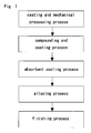
- Fig. 1 is a diagram of production processes according to an embodiment of the present invention.
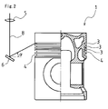
- Fig. 2 is a side view partially in section of a piston of the same.
- Fig. 3 is an enlarged view of an important part of Fig. 2 .
- Fig. 4 is a typical sectional view of a cast-iron cylinder head produced by a method of the present invention.
- Fig. 5 is an enlarged view of a part Z of Fig. 4 .
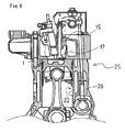
- Fig. 6 is a drawing of a liner surface of a cylinder block.
- Cast iron liquid is poured into a mold so as to cast a piston 1 of FCD (Ferrum Casting Ductile), and then piston ring grooves are processed cuttingly so as to form ring grooves 3 and 4.
- FCD Fiber Casting Ductile
- the alloy powder is mixed by a ball mill or the like so as to disperse the metal powder equally
- a fixed amount of solvent is added to the alloy powder and mixed so as to disperse the alloy powder and the solvent equally.
- a binder is added to them and stirred sufficiently so as to make them into an equal mixture.
- the ring grooves 3 and 4 are coated by a spray nozzle (not shown) with the mixture of the alloy powder, resin and solvent obtained as the above.
- the piston 1 is rotated at a fixed speed so as to form a uniform powder alloy layer (thickness of 200 to 400 ⁇ m).
- the layer is let at room temperature so as to dry the solvent sufficiently.
- metal which generates very hard carbide such as Cr, V, W, Mo or Ti.
- MC carbide very hard carbide
- alumina, TiN, TiO 2 , CrN, zirconia, SiC, TiC or the like may be used as metal forming hard alloy so as to form the powder alloy layer.
- the resin is preferably alkyd resin, but is not limited thereto.
- the solvent may be thinner, toluene, xylene or alcohol such as methanol, ethanol or propanol and is selected suitably in consideration of drying speed and safety.
- the process is given that the binder is added later to the mixture of the metal powder and the solvent.
- metal powder may alternatively be added to a mixture of solvent and a binder.
- the thickness o the powder alloy layer is preferably about 200 to 400 ⁇ m, but is not limited thereto.
- powder of only one kind of metal may alternatively be used.
- a coated thing may be entered in a drying oven or the like so as to promote drying of the solvent.
- Laser absorbent 10 is coated by a spraying nozzle on the powder alloy layer with thickness of about 5 to 15 ⁇ m corresponding to laser wavelength.
- the piston 1 is rotated at a fixed speed so as to form a uniform coat.
- the coat is let at room temperature so as to dry solvent sufficiently.
- black lead powder diluted with the solvent such as thinner is used as the laser absorbent 10 so as to form a black lead coat on the powder alloy layer.
- coating agent whose principal component is ferric oxide or the like may alternatively be coated as the absorbent.
- the diluent solvent may be thinner, toluene, xylene or alcohol such as methanol, ethanol or propanol and is selected suitably in consideration of drying speed and safety.
- laser or electron beam is applied with suitable output and scanning speed on the ring grooves 3 and 4 so as to sinter or melt the powder alloy layer, whereby an alloy layer 20 with thickness of about 150 to 350 ⁇ m is formed on the ring grooves 3 and 4.
- the laser may be CO 2 laser, YAG laser, semiconductor laser or the like.
- the electron beam having higher energy than the laser also may be used. Accordingly, by coating the laser absorbent 10 (black lead coat) at the former process, laser light 8 is absorbed efficiently to the powder alloy layer so as to heat the powder alloy layer.
- the metal base material of the piston and the like (cast iron base material) is promoted in the powder alloy layer and the interface between the powder alloy layer and the base material, whereby the alloy layer which is stable and has abrasive resistance is generated on the surface of the metal base material, and the alloy layer is bonded to the metal base material (cast iron base material).
- a member made from FCD Fluorrum Casting Ductile
- the metal base material is not limited thereto and aluminum alloy or the like may be used.
- the surface of the alloy layer 20 is grinded as occasion demands. According to the processes, the piston having the alloy layer on the ring grooves 3 and 4 is produced.
- the piston is rotated at a fixed speed along its peripheral direction so as to form the uniform coat.
- the coat is let at room temperature so as to dry the solvent sufficiently.
- the laser light 8 of CO 2 laser is applied on the ring groove 3.
- the laser light 8 is condensed by a condenser lens 5 and then applied on the upper surface with an incidence angle ⁇ by a reflecting mirror 6 while rotating the piston 1, whereby the alloy layer 20 is formed on the whole perimeter of the groove.
- either the laser light 8 may be applied while reversing the piston 1 or the laser light 8 may be applied while changing the incidence angle ⁇ of the laser light 8.
- the laser light 8 is applied with an incidence angle ⁇ as shown in Fig. 2 while an edge part 12 is masked by a masking plate 9 coated with black lead similar to the laser absorbent 10 with which the powder alloy layer on the groove is coated.
- the alloy layer 20 can be formed only in an abrasion area 11 without adjusting the thickness of the laser absorbent 10 at the edge part 12 by peeling it, whereby the edge part 12 is not melted so as to prevent failure, such as a crack, caused by melting.
- the piston that the alloy layer 20 is formed in the abrasion area 11 of the ring groove 3 is produced as mentioned above.
- the alloy layer 20 is formed on a test piece of ferrum casting ductile (30 ⁇ 100 (mm)), and the hardness of the surface is measured by a Vickers hardness meter, whereby abrasive resistance evaluation is performed.
- Vickers hardness is about 2000 Hv. It is confirmed that the alloy layer 20 is about sextuple harder than ferrum casting ductile which is the base material (whose Vickers hardness is 300 to 350 Hv).
- the interface between the powder alloy layer 20 and the test piece which is the cast iron base material is analyzed by an EDX (energy dispersive fluorescent X-ray analyzer) so as to confirm that Mo (molybdenum) is distributed gradiently, that is, the powder alloy layer 20 is bonded to the cast iron base material.
- An X-ray diffraction device is used so as to confirm that Mo is linked to C so as to generate MoC (molybdenum carbide) which is an example of ceramic alloy having high hardness and high melting point.
- binder and solvent are mixed, the surface of the metal base material is coated with the mixture uniformly so as to form the coat (powder alloy layer), and the coat is dried and is sintered, melted and dispersed by applying the laser 8 or electron beam, whereby the powder alloy layer 20 is generated on the surface of the metal base material and is bonded to the metal base material.
- MC type carbide such as MoC or VC is dispersed finely and uniformly on the surface of the ring groove of the piston of FCD so as to form the alloy layer with hardness of about 1000 to 3000 Hv easily. Accordingly, abrasive resistance or heat resistance is improved widely so as to prevent aggressive abrasion caused by combustion residue such as carbon.
- expensive alloy is used, the use is limited to the necessary part, whereby the amount of the use is small economically.
- the hardness is reduced by tempering at the temperature not less than 150°C.
- the special carbide such as MoC has high melting point and hardly coheres and becomes bulky at high temperature. Accordingly, the reduction of hardness of the surface of the ring groove following the rise of temperature of the ring grooves 3 and 4 at the time of driving an engine is prevented.
- the above-mentioned ceramic alloy which has higher corrosion resistance than steel material is formed on the surface so as to prevent corrosion caused by sulfur or the like.
- Radiofrequency quenching according to the conventional method requires tempering and grinding after quenching.
- the powder alloy layer 20 is formed uniformly with thickness of 100 to 300 ⁇ m so as to omit tempering and post processing, whereby the production cost is reduced.
- a cylinder head 15 is produced under the condition similar to the embodiment 1 except for using mixture powder of V (vanadium) and C as the metal powder.
- V vanadium
- C mixture powder of V (vanadium) and C
- an intake valve 16 and an exhaust valve 17 are vertically slidably supported through a valve system 18.
- An alloy layer 21 is formed with thickness of 150 to 350 ⁇ m on a valve seat 19, which is a sliding part of the cylinder head 15, according to the production method of the present invention.
- V is distributed gradiently and VC (vanadium carbide) is generated.
- VC is known as ceramic alloy having high hardness, high abrasive resistance and high heat resistance (with Vickers hardness of about 2500 to 2800 Hv), and is very effective for improving the abrasive resistance of the sliding part.
- the metal powder is heated and melted by the laser light 8 and sintering so that dispersing is promoted inside the alloy layer 21 and at the interface between the alloy layer 21 and the cylinder head 15 which is the base material, whereby the valve seat-integral cylinder head 15 is produced which has the alloy layer 21 having the abrasive resistance on the surface of the valve scat 19.
- the steel cylinder head 15 produced by the above processes is constructed that the valve seat 19 and the cast iron base material (cylinder head 11) are integral with each other so as to improve bonding strength of a boundary between the cylinder head 11 which is the cast iron base material and the alloy layer 21. Namely, the bonding strength is higher than that of a cast iron cylinder head of the conventional valve seat-engaging type.
- a cylinder block 25 is produced under the condition similar to the embodiment 1 except for using mixture powder of W (tungsten) and C as the metal powder.
- W tungsten
- C mixture powder of W
- an alloy layer 22 is formed with thickness of 150 to 350 ⁇ m on a liner surface 26, which is a sliding part of the cylinder block 25, according to the production method of the present invention.
- W is distributed gradiently and WC (tungsten carbide) is generated.
- WC is known as ceramic alloy having high hardness, high abrasive resistance and high heat resistance (with Vickers hardness of about 2600 to 2800 Hv), and is very effective for improving the abrasive resistance.
- the metal powder is heated and melted by the laser light 8 and sintering so that dispersing is promoted inside the alloy layer 22 and at the interface between the alloy layer 22 and the liner surface 26 of the cylinder block 25 which is the base material, whereby the cast iron cylinder block 25 is produced which has the alloy layer 22 having the abrasive resistance on the liner surface 31.
- This embodiment explains the method for forming an alloy layer having abrasive resistance and heat resistance in a metal member for an internal combustion engine.
- an alloy layer also can be formed on a surface of a member for any other use application requiring abrasive resistance so as to improve the abrasive resistance.
- the present invention can be adopted widely to not only a metal member for an internal combustion engine but also a surface of a member requiring abrasive resistance.
Landscapes
- Engineering & Computer Science (AREA)
- Chemical & Material Sciences (AREA)
- Mechanical Engineering (AREA)
- Physics & Mathematics (AREA)
- General Engineering & Computer Science (AREA)
- Optics & Photonics (AREA)
- Materials Engineering (AREA)
- Metallurgy (AREA)
- Organic Chemistry (AREA)
- Plasma & Fusion (AREA)
- Chemical Kinetics & Catalysis (AREA)
- Combustion & Propulsion (AREA)
- Thermal Sciences (AREA)
- Crystallography & Structural Chemistry (AREA)
- Manufacturing & Machinery (AREA)
- Composite Materials (AREA)
- Other Surface Treatments For Metallic Materials (AREA)
- Pistons, Piston Rings, And Cylinders (AREA)
- Powder Metallurgy (AREA)
- Cylinder Crankcases Of Internal Combustion Engines (AREA)
- Laser Beam Processing (AREA)
- Heat Treatment Of Articles (AREA)
Abstract
Description
- The present invention relates to a surface hardening method for a metal member of an engine or a driving member in the field of a transport or machine structure and a production method of the member, the member required abrasive resistance.
- Recently, crude oil becomes heavy, demand for light oil is increased and an oil refining method is changed so that fuel characteristic of low quality fuel oil is worsened. Then, parts of an internal combustion engine tend to be worn by hard particles, sulfur content, fuel residue included in fuel.
For dealing with the above situation, for example, as an art for improving abrasive resistance of a ring groove of an integral FCD (Ferrum Casting Ductile) piston used mainly in a diesel engine, there is well known and adopted widely a laser quenching art that the ring groove is quenched by laser (for example, see the Patent Literature 1), a high frequency quenching art (for example, see the Patent Literature 2) and a chromium plating art. - Patent Literature 1: the Japanese Patent Laid Open Gazette
Sho. 61-149424 - Patent Literature 2: the Japanese Patent Laid Open Gazette
Hei. 7-119831 - However, the hardness of the quenched part treated by the laser quenching art or the high frequency quenching art is about 600 to 800 Hv. The structure of the quenched part is not perfectly uniform and structures such as martensite, bainite and retained austenite are included, whereby the hardness is not uniform.
A top ring groove is susceptible to engine combustion temperature and when the ring groove is heated upper than about 150°C, the quenched structure is tempered and the hardness is reduced for about 100 to 200 Hv.
Furthermore, when the piston is made from cast iron which is corroded easily, the ring groove is corroded by sulfur or the like included in fuel gas.
Because of the above reasons, especially in an internal combustion engine, when the piston ring groove is worn by use for hours and a vertical gap is enlarged by the abrasion, lubricating oil is raised excessively by pumping action so that consumption of lubricating oil is increased. Then, when the abrasion reaches a fixed amount, the piston must be exchanged, whereby the maintenance requires cost.
The laser quenching causes many shattered cracks when the quenching depth is larger than about 300 µm so as not to be able to perform deep quenching. On the other hand, the high frequency quenching can perform quenching with depth not larger than about 800 µm, but causes large heat treatment distortion and requires post processing such as grinding. - With regard to the surface hardening by the chromium plating, the plating part is hard for about 800 to 1000 Hv and has high abrasive resistance, but the plating is very expensive. Furthermore, plating solution contains hexavalent chromium and is not preferable in consideration of influence upon the environment.
- The present invention is provided in consideration of the above problems and the purpose of the invention is to provide a surface hardening method that a surface of an engine member is coated with an alloy layer having high abrasive resistance so as to improve life of the member and a production method of a piston or the like that abrasive resistance of the member is improved by the hardening method.
- With regard to a surface hardening method for a metal member according to the present invention, a surface of a metal base material is coated uniformly with mixture including metal powder, a binder and solvent so as to form a coat, and the coat is dried and applied thereon with laser or electron beam so as to be sintered and dispersed for forming an alloy layer on a surface of the metal base material and for bonding the alloy layer to the metal base material.
- With regard to the surface hardening method for a metal member according to the present invention, the coat is coated with black lead so as to promote sintering and dispersing of the metal powder.
- With regard to the surface hardening method for a metal member according to the present invention, the metal base material is cast iron base material.
- With regard to a production method of a piston according to the present invention, the surface hardening method for a metal member as set forth in one of
claims 1 to 3 is adopted to a ring groove of a piston for an internal combustion engine. - With regard to a production method of a cylinder head according to the present invention, the surface hardening method for a metal member as set forth in one of
claims 1 to 3 is adopted to a valve seat of a cylinder head for an internal combustion engine. - With regard to a production method of a cylinder block according to the present invention, the surface hardening method for a metal member as set forth in one of
claims 1 to 3 is adopted to a liner surface of a cylinder block for an internal combustion engine. - A ring groove of the piston is hardened by the surface hardening method for a metal member as set forth in one of
claims 1 to 3. - A valve seat of the cylinder head is hardened by the surface hardening method for a metal member as set forth in one of
claims 1 to 3. - A liner surface of a cylinder block according to the present invention is hardened by the surface hardening method for a metal member as set forth in one of
claims 1 to 3. - With regard to a surface hardening method for a metal member according to the present invention, a surface of a metal base material is coated uniformly with mixture including metal powder, a binder and solvent so as to form a coat, and the coat is dried and applied thereon with laser or electron beam so as to be sintered and dispersed for forming an alloy layer on a surface of the metal base material and for bonding the alloy layer to the metal base material. Accordingly, for example, MC type carbide such as MoC or VC is dispersed finely and uniformly on the surface of the ring groove of the piston of FCD so as to form the alloy layer with hardness of about 1000 to 3000 Hv easily, thereby preventing aggressive abrasion caused by combustion residue such as carbon.
- With regard to steel material, the hardness is reduced by tempering at the temperature not less than 150°C. However, the special carbide has high melting point and hardly coheres and becomes bulky at high temperature. Accordingly, the reduction of hardness of the surface of the ring groove following the rise of temperature of the ring groove at the time of driving an engine is prevented.
- Furthermore, ceramic alloy which has higher corrosion resistance than steel material is formed on the surface so as to prevent corrosion caused by sulfur or the like.
- Radiofrequency quenching according to the conventional method requires tempering and grinding after quenching. On the other hand, according to the present invention, after cuttingly processing the ring groove, a powder alloy layer is formed uniformly with thickness of 100 to 300 µm so as to omit tempering and post processing, whereby the production cost is reduced.
-
- [
Fig. 1 ] If is a diagram of production processes according to an embodiment of the present invention. - [
Fig. 2 ] It is a side view partially in section of a piston of the same. - [
Fig. 3 ] It is an enlarged view of an important part ofFig. 2 . - [
Fig. 4 ] It is a typical sectional view of a cast-iron cylinder head produced by a method of the present invention. - [
Fig. 5 ] It is an enlarged view of a part Z ofFig. 4 . - [
Fig. 6 ] It is a drawing of a liner surface of a cylinder block. -
- 1
- a piston
- 3, 4
- ring grooves
- 8
- laser light
- 10
- laser absorbent
- 15
- a cylinder head
- 19
- a valve seat
- 20, 21, 22
- alloy layers
- 25
- a cylinder block
- 26
- a liner surface
- Next, explanation will be given on an embodiment of the present invention.
Fig. 1 is a diagram of production processes according to an embodiment of the present invention.Fig. 2 is a side view partially in section of a piston of the same.Fig. 3 is an enlarged view of an important part ofFig. 2 .Fig. 4 is a typical sectional view of a cast-iron cylinder head produced by a method of the present invention.Fig. 5 is an enlarged view of a part Z ofFig. 4 .Fig. 6 is a drawing of a liner surface of a cylinder block. - Explanation will be given on processes of production of a cast-iron cylinder for an internal combustion engine to which a surface hardening method for a metal member according to the present invention is adopted referring to
Figs. 1 ,2 and3 . - Cast iron liquid is poured into a mold so as to cast a
piston 1 of FCD (Ferrum Casting Ductile), and then piston ring grooves are processed cuttingly so as to formring grooves - Firstly, several kinds of metal powder are respectively weighed at a fixed weight and are compounded. Next, the alloy powder is mixed by a ball mill or the like so as to disperse the metal powder equally A fixed amount of solvent is added to the alloy powder and mixed so as to disperse the alloy powder and the solvent equally. Then, a binder is added to them and stirred sufficiently so as to make them into an equal mixture.
Next, thering grooves piston 1 is rotated at a fixed speed so as to form a uniform powder alloy layer (thickness of 200 to 400 µm). After forming the powder alloy layer, the layer is let at room temperature so as to dry the solvent sufficiently.
As the metal powder, it is preferable to use metal which generates very hard carbide (MC carbide) such as Cr, V, W, Mo or Ti. However, alumina, TiN, TiO2, CrN, zirconia, SiC, TiC or the like may be used as metal forming hard alloy so as to form the powder alloy layer. The resin is preferably alkyd resin, but is not limited thereto.
The solvent may be thinner, toluene, xylene or alcohol such as methanol, ethanol or propanol and is selected suitably in consideration of drying speed and safety.
As an embodiment, the process is given that the binder is added later to the mixture of the metal powder and the solvent. However, metal powder may alternatively be added to a mixture of solvent and a binder.
The thickness o the powder alloy layer is preferably about 200 to 400 µm, but is not limited thereto.
Instead of the mixture powder of several kinds of metal, powder of only one kind of metal may alternatively be used. For shortening drying time, a coated thing may be entered in a drying oven or the like so as to promote drying of the solvent. -
Laser absorbent 10 is coated by a spraying nozzle on the powder alloy layer with thickness of about 5 to 15 µm corresponding to laser wavelength. At the time of coating, thepiston 1 is rotated at a fixed speed so as to form a uniform coat. After forming the coat, the coat is let at room temperature so as to dry solvent sufficiently.
In this embodiment, black lead powder diluted with the solvent such as thinner is used as thelaser absorbent 10 so as to form a black lead coat on the powder alloy layer. However, the process is not limited thereto and coating agent whose principal component is ferric oxide or the like may alternatively be coated as the absorbent.
The diluent solvent may be thinner, toluene, xylene or alcohol such as methanol, ethanol or propanol and is selected suitably in consideration of drying speed and safety. - As shown in
Figs. 2 and3 , laser or electron beam is applied with suitable output and scanning speed on thering grooves alloy layer 20 with thickness of about 150 to 350 µm is formed on thering grooves
The laser may be CO2 laser, YAG laser, semiconductor laser or the like. The electron beam having higher energy than the laser also may be used.
Accordingly, by coating the laser absorbent 10 (black lead coat) at the former process,laser light 8 is absorbed efficiently to the powder alloy layer so as to heat the powder alloy layer. Then, sintering, melting and dispersion to the metal base material of the piston and the like (cast iron base material) is promoted in the powder alloy layer and the interface between the powder alloy layer and the base material, whereby the alloy layer which is stable and has abrasive resistance is generated on the surface of the metal base material, and the alloy layer is bonded to the metal base material (cast iron base material).
In this embodiment, a member made from FCD (Ferrum Casting Ductile) is used as the metal base material. However, the metal base material is not limited thereto and aluminum alloy or the like may be used. - With regard to the
ring grooves piston 1, the surface of thealloy layer 20 is grinded as occasion demands.
According to the processes, the piston having the alloy layer on thering grooves - Next, explanation will be given on a concrete embodiment of the production of the
piston 1.
Firstly, Mo (molybdenum) powder is weighed and added to toluene which is the solvent and mixed with a ball mill. Subsequently, a fixed amount of phthalic resin is added and the whole of them is stirred so as to be a uniform mixture.
Next, the recess of thering groove 3 is coated by the spray nozzle with the mixture uniformly while rotating the piston of FCD along its peripheral direction so as to form a powder alloy layer with thickness of about 300 µm. After forming the powder alloy layer, the layer is let at room temperature so as to dry the solvent sufficiently.
Next, the powder alloy layer is coated by the spray nozzle with thelaser absorbent 10 with thickness of about 10 µm. At the time of coating, the piston is rotated at a fixed speed along its peripheral direction so as to form the uniform coat. After forming the coat, the coat is let at room temperature so as to dry the solvent sufficiently.
As shown inFigs. 2 and3 , thelaser light 8 of CO2 laser is applied on thering groove 3. For example, in the case of forming thealloy layer 20 on the upper side surface of thering groove 3, thelaser light 8 is condensed by acondenser lens 5 and then applied on the upper surface with an incidence angle α by a reflecting mirror 6 while rotating thepiston 1, whereby thealloy layer 20 is formed on the whole perimeter of the groove. In the case of forming thealloy layer 20 on the lower side surface of thering groove 3, either thelaser light 8 may be applied while reversing thepiston 1 or thelaser light 8 may be applied while changing the incidence angle α of thelaser light 8.
In this embodiment, especially in the case of forming thealloy layer 20 on the both side surfaces of thering groove 3, thelaser light 8 is applied with an incidence angle α as shown inFig. 2 while anedge part 12 is masked by a masking plate 9 coated with black lead similar to thelaser absorbent 10 with which the powder alloy layer on the groove is coated. Accordingly, thealloy layer 20 can be formed only in anabrasion area 11 without adjusting the thickness of thelaser absorbent 10 at theedge part 12 by peeling it, whereby theedge part 12 is not melted so as to prevent failure, such as a crack, caused by melting.
The piston that thealloy layer 20 is formed in theabrasion area 11 of thering groove 3 is produced as mentioned above. - Under the production condition similar to the above processes, the
alloy layer 20 is formed on a test piece of ferrum casting ductile (30 × 100 (mm)), and the hardness of the surface is measured by a Vickers hardness meter, whereby abrasive resistance evaluation is performed. With regard to the test piece on which thealloy layer 20 is formed with Mo (molybdenum) as the above, Vickers hardness is about 2000 Hv. It is confirmed that thealloy layer 20 is about sextuple harder than ferrum casting ductile which is the base material (whose Vickers hardness is 300 to 350 Hv). - With regard to the test piece, the interface between the
powder alloy layer 20 and the test piece which is the cast iron base material is analyzed by an EDX (energy dispersive fluorescent X-ray analyzer) so as to confirm that Mo (molybdenum) is distributed gradiently, that is, thepowder alloy layer 20 is bonded to the cast iron base material. An X-ray diffraction device is used so as to confirm that Mo is linked to C so as to generate MoC (molybdenum carbide) which is an example of ceramic alloy having high hardness and high melting point. - According to the processes, binder and solvent are mixed, the surface of the metal base material is coated with the mixture uniformly so as to form the coat (powder alloy layer), and the coat is dried and is sintered, melted and dispersed by applying the
laser 8 or electron beam, whereby thepowder alloy layer 20 is generated on the surface of the metal base material and is bonded to the metal base material. By adopting the surface hardening method according to the present invention to the production of a metal member, for example, MC type carbide such as MoC or VC is dispersed finely and uniformly on the surface of the ring groove of the piston of FCD so as to form the alloy layer with hardness of about 1000 to 3000 Hv easily. Accordingly, abrasive resistance or heat resistance is improved widely so as to prevent aggressive abrasion caused by combustion residue such as carbon.
When expensive alloy is used, the use is limited to the necessary part, whereby the amount of the use is small economically. - With regard to steel material, the hardness is reduced by tempering at the temperature not less than 150°C. However, the special carbide such as MoC has high melting point and hardly coheres and becomes bulky at high temperature. Accordingly, the reduction of hardness of the surface of the ring groove following the rise of temperature of the
ring grooves - Furthermore, the above-mentioned ceramic alloy which has higher corrosion resistance than steel material is formed on the surface so as to prevent corrosion caused by sulfur or the like.
- Radiofrequency quenching according to the conventional method requires tempering and grinding after quenching. On the other hand, according to the present invention, after cuttingly processing the
ring groove 3, thepowder alloy layer 20 is formed uniformly with thickness of 100 to 300 µm so as to omit tempering and post processing, whereby the production cost is reduced. - Next, explanation will be given on an embodiment that the surface hardening method according to the present invention is adopted to a cast iron cylinder head for an internal combustion engine referring to
Figs. 4 and5 . - A
cylinder head 15 is produced under the condition similar to theembodiment 1 except for using mixture powder of V (vanadium) and C as the metal powder.
As shown inFig. 5 , in thecylinder head 15, anintake valve 16 and anexhaust valve 17 are vertically slidably supported through avalve system 18. Analloy layer 21 is formed with thickness of 150 to 350 µm on avalve seat 19, which is a sliding part of thecylinder head 15, according to the production method of the present invention. At the interface between thealloy layer 21 and thecylinder head 15 which is the cast iron base material, V is distributed gradiently and VC (vanadium carbide) is generated. Similarly to MoC of theembodiment 1, VC is known as ceramic alloy having high hardness, high abrasive resistance and high heat resistance (with Vickers hardness of about 2500 to 2800 Hv), and is very effective for improving the abrasive resistance of the sliding part. As the above, the metal powder is heated and melted by thelaser light 8 and sintering so that dispersing is promoted inside thealloy layer 21 and at the interface between thealloy layer 21 and thecylinder head 15 which is the base material, whereby the valve seat-integral cylinder head 15 is produced which has thealloy layer 21 having the abrasive resistance on the surface of thevalve scat 19. - The
steel cylinder head 15 produced by the above processes is constructed that thevalve seat 19 and the cast iron base material (cylinder head 11) are integral with each other so as to improve bonding strength of a boundary between thecylinder head 11 which is the cast iron base material and thealloy layer 21. Namely, the bonding strength is higher than that of a cast iron cylinder head of the conventional valve seat-engaging type. - Next, explanation will be given on an embodiment that the surface hardening method according to the present invention is adopted to a liner surface of a cast iron cylinder block for an internal combustion engine referring to
Fig. 6 . - A
cylinder block 25 is produced under the condition similar to theembodiment 1 except for using mixture powder of W (tungsten) and C as the metal powder.
As shown inFig. 6 , analloy layer 22 is formed with thickness of 150 to 350 µm on aliner surface 26, which is a sliding part of thecylinder block 25, according to the production method of the present invention. At the interface between thealloy layer 22 and theliner surface 26 of thecylinder block 25 which is the cast iron base material, W is distributed gradiently and WC (tungsten carbide) is generated. Similarly to MoC of theembodiment 1 and VC of the embodiment 2, WC is known as ceramic alloy having high hardness, high abrasive resistance and high heat resistance (with Vickers hardness of about 2600 to 2800 Hv), and is very effective for improving the abrasive resistance. As the above, the metal powder is heated and melted by thelaser light 8 and sintering so that dispersing is promoted inside thealloy layer 22 and at the interface between thealloy layer 22 and theliner surface 26 of thecylinder block 25 which is the base material, whereby the castiron cylinder block 25 is produced which has thealloy layer 22 having the abrasive resistance on the liner surface 31. - This embodiment explains the method for forming an alloy layer having abrasive resistance and heat resistance in a metal member for an internal combustion engine. However, an alloy layer also can be formed on a surface of a member for any other use application requiring abrasive resistance so as to improve the abrasive resistance.
- The present invention can be adopted widely to not only a metal member for an internal combustion engine but also a surface of a member requiring abrasive resistance.
Claims (9)
- A surface hardening method for a metal member characterized in that:a surface of a metal base material is coated uniformly with mixture including metal powder, a binder and solvent so as to form a coat; andthe coat is dried and applied thereon with laser or electron beam so as to be sintered anddispersed for forming an alloy layer on a surface of the metal base material and for bonding the alloy layer to the metal base material.
- The surface hardening method for a metal member as set forth in claim 1, wherein the coat is coated with black lead so as to promote sintering and dispersing of the metal powder.
- The surface hardening method for a metal member as set forth in claim 1 or 2, wherein the metal base material is cast iron base material.
- A production method for a piston characterized in that the surface hardening method for a metal member as set forth in one of claims 1 to 3 is adopted to a ring groove of a piston for an internal combustion engine.
- A production method for a cylinder head characterized in that the surface hardening method for a metal member as set forth in one of claims 1 to 3 is adopted to a valve seat of a cylinder head for an internal combustion engine.
- A production method for a cylinder block characterized in that the surface hardening method for a metal member as set forth in one of claims 1 to 3 is adopted to a liner surface of a cylinder block for an internal combustion engine.
- A piston for an internal combustion engine characterized in that a ring groove of the piston is hardened by the surface hardening method for a metal member as set forth in one of claims 1 to 3.
- A cylinder head for an internal combustion engine characterized in that a valve seat of the cylinder head is hardened by the surface hardening method for a metal member as set forth in one of claims 1 to 3.
- A cylinder block for an internal combustion engine characterized in that a liner surface of the cylinder block is hardened by the surface hardening method for a metal member as set forth in one of claims 1 to 3.
Applications Claiming Priority (2)
| Application Number | Priority Date | Filing Date | Title |
|---|---|---|---|
| JP2006136802A JP5101838B2 (en) | 2006-05-16 | 2006-05-16 | Surface hardening method for metal members |
| PCT/JP2007/054802 WO2007132587A1 (en) | 2006-05-16 | 2007-03-12 | Method of hardening surface of metallic part, piston, cylinder head, and cylinder block each produced using the surface-hardening method, and process for producing the same |
Publications (2)
| Publication Number | Publication Date |
|---|---|
| EP2025776A1 true EP2025776A1 (en) | 2009-02-18 |
| EP2025776A4 EP2025776A4 (en) | 2010-04-21 |
Family
ID=38693689
Family Applications (1)
| Application Number | Title | Priority Date | Filing Date |
|---|---|---|---|
| EP07738274A Withdrawn EP2025776A4 (en) | 2006-05-16 | 2007-03-12 | Method of hardening surface of metallic part, piston, cylinder head, and cylinder block each produced using the surface-hardening method, and process for producing the same |
Country Status (6)
| Country | Link |
|---|---|
| US (1) | US8152942B2 (en) |
| EP (1) | EP2025776A4 (en) |
| JP (1) | JP5101838B2 (en) |
| KR (2) | KR101179151B1 (en) |
| CN (2) | CN102352505B (en) |
| WO (1) | WO2007132587A1 (en) |
Cited By (6)
| Publication number | Priority date | Publication date | Assignee | Title |
|---|---|---|---|---|
| WO2010129105A1 (en) * | 2009-05-04 | 2010-11-11 | Vetco Gray Inc. | System and method for applying a coating to a substrate |
| RU2497978C2 (en) * | 2011-07-22 | 2013-11-10 | Федеральное государственное образовательное учреждение высшего профессионального образования "Ижевская государственная сельскохозяйственная академия" | Coating formation method, and plant for its implementation |
| WO2014040156A1 (en) * | 2012-09-11 | 2014-03-20 | Mahle Metal Leve S/A | An engine piston and a process for making an engine piston |
| CN105063616A (en) * | 2015-09-10 | 2015-11-18 | 桂林电子科技大学 | Modification method for cladding cylindrical surface of bar based on electron beam toroidal gun |
| WO2020092419A1 (en) * | 2018-10-29 | 2020-05-07 | Cartridge Limited | Thermally enhanced exhaust port liner |
| EP4105345A4 (en) * | 2020-04-16 | 2023-08-02 | Mitsubishi Heavy Industries Engine & Turbocharger, Ltd. | Cylinder head, cylinder block, internal combustion engine, and method for manufacturing cylinder head |
Families Citing this family (28)
| Publication number | Priority date | Publication date | Assignee | Title |
|---|---|---|---|---|
| JP5298726B2 (en) * | 2008-09-17 | 2013-09-25 | 株式会社豊田中央研究所 | Method for forming thin film and method for manufacturing internal combustion engine |
| JP5258611B2 (en) * | 2009-02-10 | 2013-08-07 | 三菱電機株式会社 | Iron-based material |
| JP5482550B2 (en) * | 2010-08-03 | 2014-05-07 | 株式会社デンソー | Powertrain product manufacturing method |
| DE102010060385A1 (en) * | 2010-11-05 | 2012-05-10 | Dorma Gmbh + Co. Kg | UV laser exposure of housings and components of door drives and door closers |
| JP5981193B2 (en) * | 2012-03-30 | 2016-08-31 | 日立オートモティブシステムズ株式会社 | Plating parts manufacturing method and cylinder device manufacturing method |
| US8672018B2 (en) * | 2012-08-20 | 2014-03-18 | GM Global Technology Operations LLC | Cylinder head and method |
| WO2014047698A1 (en) * | 2012-09-26 | 2014-04-03 | Mahle Metal Leve S/A | Cylinder liner |
| CN103225565A (en) * | 2013-04-07 | 2013-07-31 | 江苏爱吉斯海珠机械有限公司 | Cylinder liner of high-horsepower diesel engine and production method thereof |
| CN105324182B (en) * | 2013-04-18 | 2018-03-02 | Dm3D技术有限责任公司 | Laser assisted interstitial alloy for improve wearability |
| JP5858007B2 (en) * | 2013-07-01 | 2016-02-10 | トヨタ自動車株式会社 | Overlaying method for valve seat and manufacturing method of cylinder head |
| DE102014214689A1 (en) * | 2014-07-25 | 2016-01-28 | Bayerische Motoren Werke Aktiengesellschaft | Method for the production of a valve body of a valve of an internal combustion engine |
| CN104439674B (en) * | 2014-11-11 | 2016-11-23 | 中国兵器科学研究院宁波分院 | A kind of electron beam alloy strengthening method of aluminium-silicon alloy piston annular groove |
| JP2016172893A (en) * | 2015-03-17 | 2016-09-29 | セイコーエプソン株式会社 | 3D forming apparatus and 3D forming method |
| CN105132913B (en) * | 2015-09-22 | 2018-01-12 | 山东大学 | A kind of laser cladding alloy powder remanufactured for hot-work die reparation |
| JP6614183B2 (en) * | 2017-02-27 | 2019-12-04 | トヨタ自動車株式会社 | Automotive panel materials |
| CN107842435A (en) * | 2017-10-20 | 2018-03-27 | 奇瑞汽车股份有限公司 | The high tumble inlet port of direct spray petrol engine in cylinder |
| KR102064766B1 (en) | 2017-11-15 | 2020-01-13 | 한국생산기술연구원 | Laser Deposition Apparatus Having Abandoned Metal Powder Inhalation Unit |
| DE102018003730A1 (en) * | 2018-05-08 | 2019-11-14 | Adrian Boos | 3D printing process by means of one or more hydrogen flames and an optional process for three-dimensional hardening of the workpiece |
| JP7620297B2 (en) * | 2018-05-22 | 2025-01-23 | 国立大学法人 名古屋工業大学 | Structural member and manufacturing method thereof |
| WO2019236960A1 (en) * | 2018-06-08 | 2019-12-12 | S.P.M. Flow Control, Inc. | Cladded valve seat, assembly, and methods for cladding such seat |
| WO2020003462A1 (en) * | 2018-06-28 | 2020-01-02 | 日産自動車株式会社 | Method for manufacturing cylinder head, and cylinder head rough material |
| CN109482877B (en) * | 2018-12-19 | 2021-06-01 | 北京航星机器制造有限公司 | Application of laser absorption coating to additive manufacturing |
| CN111593340B (en) * | 2020-05-08 | 2022-06-07 | 陕西天元智能再制造股份有限公司 | Laser cladding method for inner wall of hydraulic support oil cylinder |
| KR102388569B1 (en) | 2020-12-08 | 2022-04-22 | 한국생산기술연구원 | Chamber Assembly for Metal Powder Deposition for Defective Restraint Using Oxygen Saturation Control |
| CN112475304B (en) * | 2020-12-09 | 2021-09-28 | 福州大学 | 12Cr stainless steel surface strengthening method based on spark plasma sintering |
| US20220314372A1 (en) * | 2021-03-30 | 2022-10-06 | GM Global Technology Operations LLC | System and method for making an enhanced cast iron workpiece having increased lubricant retention |
| CN117162606B (en) * | 2023-08-31 | 2025-12-30 | 西安工业大学 | Composite materials for diesel engine cylinder head components and their preparation methods |
| CN117512277A (en) * | 2023-11-10 | 2024-02-06 | 湖南江滨机器(集团)有限责任公司 | A piston ring groove laser quenching auxiliary device, system and method |
Family Cites Families (33)
| Publication number | Priority date | Publication date | Assignee | Title |
|---|---|---|---|---|
| US3618960A (en) * | 1970-06-16 | 1971-11-09 | Max Koehler | Piston ring |
| US4015100A (en) * | 1974-01-07 | 1977-03-29 | Avco Everett Research Laboratory, Inc. | Surface modification |
| US4157923A (en) * | 1976-09-13 | 1979-06-12 | Ford Motor Company | Surface alloying and heat treating processes |
| JPS5948873B2 (en) * | 1980-05-14 | 1984-11-29 | ペルメレック電極株式会社 | Method for manufacturing electrode substrate or electrode provided with corrosion-resistant coating |
| DE3100755A1 (en) * | 1981-01-13 | 1982-09-02 | Klöckner-Humboldt-Deutz AG, 5000 Köln | CYLINDER HEAD FOR AN INTERNAL COMBUSTION ENGINE |
| IT1179061B (en) * | 1984-08-20 | 1987-09-16 | Fiat Auto Spa | PROCEDURE FOR CARRYING OUT A TREATMENT ON METAL PIECES WITH THE ADDITION OF A VALUE MATERIAL AND WITH THE USE OF A POWER LASER |
| JPS61149424A (en) | 1984-12-24 | 1986-07-08 | Yanmar Diesel Engine Co Ltd | Laser quenching method of member constituted of recessed and projected part |
| JPS63280961A (en) * | 1987-05-12 | 1988-11-17 | Mitsubishi Heavy Ind Ltd | Manufacture of sliding member |
| JPH01104487A (en) * | 1987-10-16 | 1989-04-21 | Ishikawajima Harima Heavy Ind Co Ltd | Laser overlay method for cast iron cylinder liners |
| JP3148463B2 (en) * | 1993-05-11 | 2001-03-19 | 日本合成化学工業株式会社 | Agricultural film |
| JPH07119831A (en) | 1993-10-21 | 1995-05-12 | Mitsubishi Heavy Ind Ltd | Piston for reciprocating engine |
| GB2288351B (en) * | 1994-04-08 | 1998-03-18 | Cutting & Wear Resistant Dev | Method for facing a substrate |
| US5515770A (en) * | 1994-12-05 | 1996-05-14 | Clark Industries, Inc. | Piston having laser hardened primary compression ring groove and method of making same |
| DE19537848A1 (en) * | 1995-10-11 | 1997-04-17 | Mahle Gmbh | Reinforcement part, the base material of which is austenitic cast iron |
| US5961861A (en) * | 1996-01-15 | 1999-10-05 | The University Of Tennessee Research Corporation | Apparatus for laser alloying induced improvement of surfaces |
| CZ215398A3 (en) * | 1996-01-15 | 1999-01-13 | The University Of Tennessee Research Corporation | Enhancing surfaces by making use of a laser |
| JPH09295173A (en) * | 1996-05-01 | 1997-11-18 | Nissan Motor Co Ltd | Method and apparatus for manufacturing piston for internal combustion engine |
| TW472089B (en) | 1996-09-17 | 2002-01-11 | Toyo Kohan Co Ltd | Surface treated steel sheet with low contact resistance and connection terminal material produced thereof |
| US5920017A (en) * | 1997-10-30 | 1999-07-06 | Westinghouse Savannah River Company | Thermal input control and enhancement for laser based residual stress measurements using liquid temperature indicating coatings |
| US6016783A (en) * | 1998-12-28 | 2000-01-25 | Detriot Diesel Corporation | Engine cylinder head having induction hardened surfaces resistant to fastener bolt stresses |
| DE19907105A1 (en) * | 1999-02-19 | 2000-08-31 | Volkswagen Ag | Method and device for producing wear-resistant, tribological cylinder running surfaces |
| DE19918808A1 (en) * | 1999-04-26 | 2000-11-02 | Mahle Gmbh | Process for hardening ring grooves with laser beams |
| US6328026B1 (en) * | 1999-10-13 | 2001-12-11 | The University Of Tennessee Research Corporation | Method for increasing wear resistance in an engine cylinder bore and improved automotive engine |
| KR20030021916A (en) * | 2001-09-10 | 2003-03-15 | 현대자동차주식회사 | A compound of wear-resistant sintered alloy for valve seat and its manufacturing method |
| DE10156196C1 (en) * | 2001-11-15 | 2003-01-02 | Daimler Chrysler Ag | Production of a valve seat used for a cylinder head of internal combustion engine comprises fusing an additive material made from an alloy or a mixture of an aluminum-lead alloy and a further component at a certain point on a cylinder head |
| CN1252315C (en) * | 2002-12-20 | 2006-04-19 | 清华大学 | Direct laser synthesis and making process of hard alloy coating |
| CN1517449A (en) * | 2003-01-16 | 2004-08-04 | 江 王 | Surface treatment method under control of laser energy and parts treated by said method |
| DE10319494A1 (en) * | 2003-04-30 | 2004-11-18 | Mtu Aero Engines Gmbh | Process for repairing and / or modifying components of a gas turbine |
| CN1255575C (en) * | 2003-08-01 | 2006-05-10 | 潜江市江汉工具厂 | Self-protective laser smelting cover productive technology for ultrafine active hard alloy |
| JP4452661B2 (en) * | 2005-07-08 | 2010-04-21 | トヨタ自動車株式会社 | Cast-in part, cylinder block, cast-in part coating method and cylinder block manufacturing method |
| US20070141375A1 (en) * | 2005-12-20 | 2007-06-21 | Budinger David E | Braze cladding for direct metal laser sintered materials |
| US20070254111A1 (en) * | 2006-04-26 | 2007-11-01 | Lineton Warran B | Method for forming a tribologically enhanced surface using laser treating |
| JP4802895B2 (en) * | 2006-07-05 | 2011-10-26 | トヨタ自動車株式会社 | Cast iron member manufacturing method, cast iron member, and vehicle engine |
-
2006
- 2006-05-16 JP JP2006136802A patent/JP5101838B2/en not_active Expired - Fee Related
-
2007
- 2007-03-12 CN CN201110308787.4A patent/CN102352505B/en not_active Expired - Fee Related
- 2007-03-12 CN CN2007800238200A patent/CN101484611B/en not_active Expired - Fee Related
- 2007-03-12 KR KR1020117022421A patent/KR101179151B1/en active Active
- 2007-03-12 KR KR1020087030625A patent/KR20090028529A/en not_active Ceased
- 2007-03-12 US US12/301,128 patent/US8152942B2/en not_active Expired - Fee Related
- 2007-03-12 EP EP07738274A patent/EP2025776A4/en not_active Withdrawn
- 2007-03-12 WO PCT/JP2007/054802 patent/WO2007132587A1/en not_active Ceased
Cited By (11)
| Publication number | Priority date | Publication date | Assignee | Title |
|---|---|---|---|---|
| WO2010129105A1 (en) * | 2009-05-04 | 2010-11-11 | Vetco Gray Inc. | System and method for applying a coating to a substrate |
| RU2497978C2 (en) * | 2011-07-22 | 2013-11-10 | Федеральное государственное образовательное учреждение высшего профессионального образования "Ижевская государственная сельскохозяйственная академия" | Coating formation method, and plant for its implementation |
| WO2014040156A1 (en) * | 2012-09-11 | 2014-03-20 | Mahle Metal Leve S/A | An engine piston and a process for making an engine piston |
| US9611803B2 (en) | 2012-09-11 | 2017-04-04 | Mahle Metal Leve S/A | Engine piston and a process for making an engine piston |
| CN105063616A (en) * | 2015-09-10 | 2015-11-18 | 桂林电子科技大学 | Modification method for cladding cylindrical surface of bar based on electron beam toroidal gun |
| CN105063616B (en) * | 2015-09-10 | 2017-08-04 | 桂林电子科技大学 | A kind of method of modifying based on the annular rifle cladding bar face of cylinder of electron beam |
| WO2020092419A1 (en) * | 2018-10-29 | 2020-05-07 | Cartridge Limited | Thermally enhanced exhaust port liner |
| US10989137B2 (en) | 2018-10-29 | 2021-04-27 | Cartridge Limited | Thermally enhanced exhaust port liner |
| EP4105345A4 (en) * | 2020-04-16 | 2023-08-02 | Mitsubishi Heavy Industries Engine & Turbocharger, Ltd. | Cylinder head, cylinder block, internal combustion engine, and method for manufacturing cylinder head |
| US11994084B2 (en) | 2020-04-16 | 2024-05-28 | Mitsubishi Heavy Industries Engine & Turbocharger, Ltd. | Cylinder head, cylinder block, internal combustion engine, and method for manufacturing cylinder head |
| US12158120B2 (en) | 2020-04-16 | 2024-12-03 | Mitsubishi Heavy Industries Engine & Turbocharger, Ltd. | Cylinder head, cylinder block, internal combustion engine, and method for manufacturing cylinder head |
Also Published As
| Publication number | Publication date |
|---|---|
| CN101484611B (en) | 2012-03-28 |
| KR20110119834A (en) | 2011-11-02 |
| WO2007132587A1 (en) | 2007-11-22 |
| US8152942B2 (en) | 2012-04-10 |
| JP5101838B2 (en) | 2012-12-19 |
| CN102352505B (en) | 2014-07-16 |
| JP2007308736A (en) | 2007-11-29 |
| US20090255504A1 (en) | 2009-10-15 |
| KR101179151B1 (en) | 2012-09-07 |
| KR20090028529A (en) | 2009-03-18 |
| CN102352505A (en) | 2012-02-15 |
| CN101484611A (en) | 2009-07-15 |
| EP2025776A4 (en) | 2010-04-21 |
Similar Documents
| Publication | Publication Date | Title |
|---|---|---|
| US8152942B2 (en) | Method of hardening surface of metallic part, piston, cylinder head, and cylinder block each produced using the surface-hardening method, and process for producing the same | |
| CA2332944C (en) | Light metal cylinder block, method for producing same and device for carrying out the method | |
| Rastegar et al. | Alternative to chrome: HVOF cermet coatings for high horse power diesel engines | |
| Zafar et al. | Development and characterisations of WC–12Co microwave clad | |
| US6328026B1 (en) | Method for increasing wear resistance in an engine cylinder bore and improved automotive engine | |
| Singh et al. | Enhancing Tribological Performance of SS-316 Through Microwave Cladding of NiCr-Cr3C2 Composite: Fabrication, Characterization, and Optimization: P. Singh, Amit Bansal, Goyal, Anuj Bansal, and V. Singh | |
| Bharath et al. | Optimization of process parameters for deposition of Stellite on X45CrSi93 steel by plasma transferred arc technique | |
| CN101473066B (en) | Wear protection device and method for the production thereof | |
| Hebbale et al. | A comparative study on characteristics of composite (Cr3C2-NiCr) clad developed through diode laser and microwave energy | |
| Hebbale et al. | An experimental investigation of microwave developed nickel-based clads for slurry erosion wear performance using taguchi approach | |
| Hebbale et al. | Microstructural studies of cobalt based microwave clad developed on martensitic stainless steel (AISI-420) | |
| Hwang et al. | Correlation of microstructure and wear resistance of ferrous coatings fabricated by atmospheric plasma spraying | |
| More et al. | Effect of Ni addition on the metallurgical and mechanical properties of WC–10Co–4Cr laser cladding surfaces on mild steel | |
| RU2310089C2 (en) | Piston for large-capacity engine and method of making wear protective layer of such piston (versions) | |
| JP2013092150A (en) | Surface hardening method for valve seat of cast-iron cylinder head for internal combustion engine | |
| Batwa et al. | Microstructure and mechanical properties of cold-sprayed Ni/CrC-NiCr composites with varying binder phases | |
| Hwang et al. | Effect of oxides on wear resistance and surface roughness of ferrous coated layers fabricated by atmospheric plasma spraying | |
| KR19990009039A (en) | Engine tappet with excellent wear resistance and its manufacturing method | |
| JP2013083003A (en) | Hardening treatment method of liner surface part of cast iron cylinder block for internal combustion engine | |
| JP5480203B2 (en) | Surface hardening method for metal members | |
| Seraj et al. | Microstructural evolution and wear resistance of friction stir-processed AISI 52100 steel | |
| RU2038406C1 (en) | Mixture for coating application | |
| Guan et al. | Microstructure Evolution and Mechanical Property Enhancement of 30CrMnSiNi2A Steel Repaired by Laser Cladding with AerMet100 Steel | |
| Shu et al. | Study on microstructure of laser cladding fe-based coatings and comparison of mechanical properties with SKD11 steel | |
| Zohuri | Laser surface processing |
Legal Events
| Date | Code | Title | Description |
|---|---|---|---|
| PUAI | Public reference made under article 153(3) epc to a published international application that has entered the european phase |
Free format text: ORIGINAL CODE: 0009012 |
|
| 17P | Request for examination filed |
Effective date: 20081216 |
|
| AK | Designated contracting states |
Kind code of ref document: A1 Designated state(s): AT BE BG CH CY CZ DE DK EE ES FI FR GB GR HU IE IS IT LI LT LU LV MC MT NL PL PT RO SE SI SK TR |
|
| AX | Request for extension of the european patent |
Extension state: AL BA HR MK RS |
|
| A4 | Supplementary search report drawn up and despatched |
Effective date: 20100319 |
|
| 17Q | First examination report despatched |
Effective date: 20110401 |
|
| STAA | Information on the status of an ep patent application or granted ep patent |
Free format text: STATUS: THE APPLICATION IS DEEMED TO BE WITHDRAWN |
|
| 18D | Application deemed to be withdrawn |
Effective date: 20110812 |