EP2025609A2 - Carton, blanks for forming a carton, package and method of dispensing articles from a carton - Google Patents
Carton, blanks for forming a carton, package and method of dispensing articles from a carton Download PDFInfo
- Publication number
- EP2025609A2 EP2025609A2 EP08162446A EP08162446A EP2025609A2 EP 2025609 A2 EP2025609 A2 EP 2025609A2 EP 08162446 A EP08162446 A EP 08162446A EP 08162446 A EP08162446 A EP 08162446A EP 2025609 A2 EP2025609 A2 EP 2025609A2
- Authority
- EP
- European Patent Office
- Prior art keywords
- carton
- strap
- articles
- dispensing
- brake
- Prior art date
- Legal status (The legal status is an assumption and is not a legal conclusion. Google has not performed a legal analysis and makes no representation as to the accuracy of the status listed.)
- Withdrawn
Links
- 238000000034 method Methods 0.000 title claims description 16
- 230000000694 effects Effects 0.000 claims description 8
- 230000005484 gravity Effects 0.000 claims description 3
- 239000003292 glue Substances 0.000 description 17
- 238000010276 construction Methods 0.000 description 9
- 238000004026 adhesive bonding Methods 0.000 description 4
- 230000015572 biosynthetic process Effects 0.000 description 3
- 238000004519 manufacturing process Methods 0.000 description 2
- 239000000463 material Substances 0.000 description 1
- 238000012856 packing Methods 0.000 description 1
- 239000011087 paperboard Substances 0.000 description 1
- 239000002245 particle Substances 0.000 description 1
- 238000009877 rendering Methods 0.000 description 1
- 238000004904 shortening Methods 0.000 description 1
- 238000003860 storage Methods 0.000 description 1
- 239000012780 transparent material Substances 0.000 description 1
Images





Classifications
-
- B—PERFORMING OPERATIONS; TRANSPORTING
- B65—CONVEYING; PACKING; STORING; HANDLING THIN OR FILAMENTARY MATERIAL
- B65D—CONTAINERS FOR STORAGE OR TRANSPORT OF ARTICLES OR MATERIALS, e.g. BAGS, BARRELS, BOTTLES, BOXES, CANS, CARTONS, CRATES, DRUMS, JARS, TANKS, HOPPERS, FORWARDING CONTAINERS; ACCESSORIES, CLOSURES, OR FITTINGS THEREFOR; PACKAGING ELEMENTS; PACKAGES
- B65D5/00—Rigid or semi-rigid containers of polygonal cross-section, e.g. boxes, cartons or trays, formed by folding or erecting one or more blanks made of paper
- B65D5/42—Details of containers or of foldable or erectable container blanks
- B65D5/72—Contents-dispensing means
- B65D5/724—Internal fittings facilitating the discharge of contents, e.g. guiding panels, movable bottoms or lifting strips
-
- B—PERFORMING OPERATIONS; TRANSPORTING
- B65—CONVEYING; PACKING; STORING; HANDLING THIN OR FILAMENTARY MATERIAL
- B65D—CONTAINERS FOR STORAGE OR TRANSPORT OF ARTICLES OR MATERIALS, e.g. BAGS, BARRELS, BOTTLES, BOXES, CANS, CARTONS, CRATES, DRUMS, JARS, TANKS, HOPPERS, FORWARDING CONTAINERS; ACCESSORIES, CLOSURES, OR FITTINGS THEREFOR; PACKAGING ELEMENTS; PACKAGES
- B65D5/00—Rigid or semi-rigid containers of polygonal cross-section, e.g. boxes, cartons or trays, formed by folding or erecting one or more blanks made of paper
- B65D5/42—Details of containers or of foldable or erectable container blanks
- B65D5/54—Lines of weakness to facilitate opening of container or dividing it into separate parts by cutting or tearing
- B65D5/5405—Lines of weakness to facilitate opening of container or dividing it into separate parts by cutting or tearing for opening containers formed by erecting a blank in tubular form
- B65D5/541—Lines of weakness to facilitate opening of container or dividing it into separate parts by cutting or tearing for opening containers formed by erecting a blank in tubular form the lines of weakness being provided in one or more closure flaps
-
- B—PERFORMING OPERATIONS; TRANSPORTING
- B65—CONVEYING; PACKING; STORING; HANDLING THIN OR FILAMENTARY MATERIAL
- B65D—CONTAINERS FOR STORAGE OR TRANSPORT OF ARTICLES OR MATERIALS, e.g. BAGS, BARRELS, BOTTLES, BOXES, CANS, CARTONS, CRATES, DRUMS, JARS, TANKS, HOPPERS, FORWARDING CONTAINERS; ACCESSORIES, CLOSURES, OR FITTINGS THEREFOR; PACKAGING ELEMENTS; PACKAGES
- B65D5/00—Rigid or semi-rigid containers of polygonal cross-section, e.g. boxes, cartons or trays, formed by folding or erecting one or more blanks made of paper
- B65D5/42—Details of containers or of foldable or erectable container blanks
- B65D5/64—Lids
- B65D5/66—Hinged lids
- B65D5/6602—Hinged lids formed by folding one or more extensions hinged to the upper edge of a tubular container body
-
- B—PERFORMING OPERATIONS; TRANSPORTING
- B65—CONVEYING; PACKING; STORING; HANDLING THIN OR FILAMENTARY MATERIAL
- B65D—CONTAINERS FOR STORAGE OR TRANSPORT OF ARTICLES OR MATERIALS, e.g. BAGS, BARRELS, BOTTLES, BOXES, CANS, CARTONS, CRATES, DRUMS, JARS, TANKS, HOPPERS, FORWARDING CONTAINERS; ACCESSORIES, CLOSURES, OR FITTINGS THEREFOR; PACKAGING ELEMENTS; PACKAGES
- B65D83/00—Containers or packages with special means for dispensing contents
- B65D83/76—Containers or packages with special means for dispensing contents for dispensing fluent contents by means of a piston
- B65D83/768—Containers or packages with special means for dispensing contents for dispensing fluent contents by means of a piston the piston or movable bottom being pulled upwards to dispense the contents
Definitions
- the invention relates to a carton for accommodating one or more articles, for example bottles, which carton is provided with a dispensing structure for removal of the articles from the carton.
- the invention also relates to one or more blanks for the construction of a carton and to packages comprising a carton containing articles.
- a problem associated with the prior art is the difficulty a user faces when removing vertically aligned articles from a carton when the carton is stored upright.
- the present invention and its embodiments seek to overcome the problems of the prior art.
- the invention provides a carton for containing a plurality of articles, the carton comprising a vertical dispensing structure for dispensing one or more articles through an upper aperture, the dispensing structure comprising a strap having a first end portion hingedly secured to a first wall of the carton and a having second free end of the strap, a portion of the strap between said first end and said second free end being positionable beneath a terminal article held within the carton such that pulling the second free end of the strap out of carton effects a dispensing of articles through the upper aperture.
- the first end portion of the strap is attached to a hinged flap which is struck from or connected to said first wall of the carton.
- the first end portion of the strap is attached to a hinged flap such that the first end portion of the strap is maintained in a substantially flat position during dispensing of articles.
- the strap is positioned to correspond with the centre of gravity of the terminal article.
- a brake is provided for applying a frictional force to the strap.
- a second wall opposed to said first wall comprises a brake aperture, wherein the brake presses a portion of the strap into the brake aperture to provide the frictional force, such that the strap is able to bear the weight of the terminal article.
- the invention provides a package comprising: one or more articles and a carton comprising a vertical dispensing structure for dispensing one or more articles through an upper aperture, the dispensing structure comprising a strap having a first end portion hingedly secured to a first wall of the carton and a having second free end of the strap, a portion of the strap between said first end and said second free end being positionable beneath a terminal article held within the carton such that pulling the second free end of the strap out of carton effects a dispensing of articles through the upper aperture.
- the invention provides a method of dispensing articles from a carton comprising a vertical dispensing structure for dispensing one or more articles through an upper aperture, the dispensing structure comprising a strap having a first end portion hingedly secured to a first wall of the carton and a having second free end of the strap, a portion of the strap between said first end and said second free end being positionable beneath a terminal article held within the carton; providing force to pull the the second free end of the strap upwardly out of carton thus lifting said vertical dispensing structure and said articles; and retrieving the uppermost article through said upper aperture.
- said carton further comprises a brake and wherein said method further comprises applying a frictional force to said strap through the use of said brake.
- the invention provides for containing a plurality of articles, the carton comprising a vertical dispensing structure for dispensing one or more articles through an upper aperture, wherein the dispensing structure comprises an elongate member with a handle means at a distal end and a portion engageable with a terminal article contained therein and wherein the elongate member comprises an insert.
- a portion of the elongate member comprises at least one elevation panel, wherein, in use, a terminal article held therein rests on the elevation panel such that an upward force exerted on the elongate member raises the article for dispensing at the upper aperture and wherein the elevation panel is reinforced by a gusset portion attached at a first end of the elevation panel and at a second end to the elongate member.
- Embodiments of the present invention provide a carton for containing a plurality of articles, the carton comprising a vertical dispensing structure for dispensing one or more articles through an upper aperture.
- the dispensing structure comprises an elongate member with a handle means at a distal end, and a portion engagable with a terminal article contained therein.
- the dispensing structure comprises a first insert sized to fit within the carton.
- the portion engagable with a terminal article comprises at least one elevation panel, wherein, in use, a terminal article contained in the carton rests on the elevation panel such that an upward force exerted on the handle raises the article for dispensing at the upper aperture.
- the elevation panel is perpendicular to the handle.
- the elevation panel is reinforced by a gusset portion attached at a first end to the elevation panel and at a second end to the handle panel.
- the insert is adapted and arranged to be folded flat, for ease of transport.
- the dispensing structure comprises a strap attached at, or proximate, a second end thereof to a side panel of the carton, such that the strap may extend beneath a terminal article held therein to present the distal end over or through an opposing side panel, wherein a pull force exerted upon the distal end effects a dispensing of particles through the upper aperture.
- the second end of the strap is attached to a hinged flap which is struck from or connected to the side panel, wherein the hinged flap aids optimal alignment of the strap beneath articles held within the carton.
- the strap is positioned to correspond with the centre of gravity of articles held within the carton.
- the carton further comprises a brake for applying a frictional force to the elongate member.
- the opposing side panel comprises a brake aperture, wherein the brake presses a portion of the strap into the brake aperture to provide the frictional force, such that the strap is able to bear the weight of articles contained within the carton.
- the carton is sized to fit within the door compartment of a domestic refrigerator.
- the invention comprises one or more blanks for constructing the embodiments described herein.
- the invention in another aspect, relates to a package comprising: a carton for containing a plurality of articles, the carton comprising a vertical dispensing structure for dispensing one or more articles through an upper aperture; and, one or more articles held within the carton.
- a carton and a blank for forming a carton there is shown a carton and a blank for forming a carton.
- the blank and carton are formed in paperboard or other foldable sheet material, for example plastic and the like, to which has been added cut and fold lines.
- the cartons are used to house one or more articles, for example bottles, and to dispense the articles through an upper aperture, the upper aperture positioned at or towards the intended upper surface of the carton.
- first blank 10 for forming a carton.
- the first blank comprises a first side panel 12, a second side panel 14, a third side panel 16 and a fourth side panel 18 hingedly connected in series along the fold lines 20, 22 and 24 respectively.
- a first end wall structure 28 is provided by first end wall panels 30, 32, hingedly attached to the opposing second and fourth side panels 14 and 18.
- An access structure 38 is provided by access panels 40, 42, hingedly attached to the second and fourth side panels 14 and 18 respectively, and access flaps 46, 48 hingedly attached to the first and third side panels 12 and 16 respectively.
- the access panels 40, 42 comprise curved cut lines 21a, 21b and 21c, 21d respectively.
- the curved cut lines 21a, 21b are joined by a fold line 23a.
- the curved cut lines 21c, 21d are joined by a fold line 23b.
- a line of perforation 25a joins the curved cut 21a to the intersection of the folds 20 and 41.
- a line of perforation 25b joins the curved cut 21b to the intersection of the folds 22 and 41.
- a line of perforation 25c joins the curved cut 21c to the intersection of the folds 24 and 43.
- a line of perforation 25d joins the curved cut 21d to the intersection of the fold 23 and the outer edge 29 of the fourth side panel 18.
- Optional apertures 44 may be provided through one or more of the side panels 12, 14, 16, 18, such that in use, the user can see the contents of the carton.
- the aperture 44 may be closed by a transparent material.
- One further embodiment of the present invention is apparent through the Figures identified above and is a method of dispensing articles, said method comprising: providing a carton comprising one or more articles contained therein, a vertical dispensing structure having an elongate member said elongate member comprising a first distal end and a second end engageable with a terminal article, and an upper aperture; providing force to said elongate member to effect the upward movement of said vertical dispensing structure and said articles; and retrieving the uppermost article through said upper aperture.
- Each of the features of the embodiments of the carton(s) and package(s) identified above and below may be incorporated into the method of dispensing articles disclosed thus, allowing for various embodiments of the method of dispensing articles.
- a vertical dispensing insert 51 is provided by a second blank.
- a first handle panel 50 is hingedly attached to an elevation panel 52a along a fold line 54a.
- Elevation flaps 56a, 56b are further hingedly attached to the elevation panel 52a along the fold lines 58a, 58b, and are defined at their outer edges by the cut lines 60a, 60b.
- the cut lines 60a and 60b define a first angle with the fold lines 58a and 58b respectively.
- the first angle measures approximately 45°.
- Gusset flaps 62a, 62b are hingedly attached to the sides of the handle panel 50 along the fold lines 66a, 66b respectively.
- the gusset flaps 62a, 62b are preferably partially defined by cut lines 68a, 68b respectively, each of the cut lines 68a, 68b being coaxial with the fold line 54a.
- the gusset flaps 62a, 62b are divided into gusset sides 70a, 70b and gusset closure tabs 72a, 72b by fold lines 74a, 74b.
- Each of these fold lines 74a, 74b defines a second angle with the cut lines 68a, 68b respectively.
- the second angle is of equal magnitude to the first angle. More preferably, the second angle is approximately 45°
- a handle aperture 76a may be formed in the handle panel 50.
- the handle 76a comprises a cut line 78 which forms all but one side of a planar shape.
- the final side of this planar shape comprises a fold line 80, to define a handle flap 82.
- a second handle panel 84 is hingedly attached to the first handle panel 50 along a fold line 86.
- the second handle panel is preferably a mirror image of the first handle panel 50, being hingedly attached to corresponding gusset flaps 62c, 62d and an elevation panel 52b.
- the elevation panel 52b being, in turn, hingedly attached to elevation flaps 56c, 56d.
- the complete second blank is symmetric about fold line 86.
- a simple folding and gluing procedure is required.
- the folding and gluing operations can be performed in one or more straight-line machines, so that the carton is not required to be rotated or inverted to complete its construction.
- the folding process is not limited to that described below and can be altered according to particular manufacturing requirements.
- the securing flap 26 is folded inwardly along the fold line 27.
- glue or some other securing means is provided along the securing flap 26.
- Glue or other securing means may also be provided along the outer edge of the fourth side panel 18.
- the first blank 10 is then folded along the fold line 22 to bring the fourth side panel 18 into face contacting arrangement with the securing flap 26, to provide a tubular structure, and is secured thereto by the glue or other such securing means as used.
- the carton is in a flat collapsed form ready to be supplied to an end user or converting plant for loading, or to move on to the next stage of the construction and erecting process.
- the first handle panel 50 and second handle panel 84 are folded along the fold line 86 to effect a back-to-back formation.
- Glue may have been applied to points on the rear of one or each of the first and second handle panels 50, 84 to secure them in back-to-back formation.
- the elevation panel 52a is then folded outwardly along the fold line 54a.
- the elevation flaps 56a, 56b are also folded outwardly along the fold lines 58a, 58b respectively, as are the gusset flaps 62a, 62b along the fold tines 66a, 66b respectively.
- Glue is applied to the gusset closure tabs 72a, 72b.
- the elevation flaps 56a, 56b are then brought into face contacting arrangement with the gusset closure tabs 72a, 72b respectively to secure the elevation panel 52a in a position substantially perpendicular to the first handle panel 50, supported by the gusset structure 88a.
- the process is then repeated to the secure elevation panel 52b in a position perpendicular to the second handle panel 84, supported by the gusset structure 88b.
- the gusset structures 88a, 88b can be flattened by folding along the fold lines 74a, 74b, 74c, 74d, such that the elevation panels 52a, 52b are in face contacting arrangement with the handle panels 50, 84.
- the flattened dispensers may then be packed more efficiently into storage.
- first end flaps 34, 36 are folded inwardly along the fold lines 35, 37 respectively, and glue or some other securing means is provided along the first end flaps 34, 36.
- the first end panels 30, 32 are then folded inwardly along the fold lines 31, 33 respectively to bring each of the first end panels 30, 32 into face contacting arrangement with a portion of the first end flaps 34, 36.
- the first end panels 30, 32 are then secured, between them covering the entire width between opposing side panels.
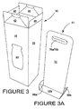
- Figure 3 shows the carton 90, with the access structure 38 open, ready for loading.
- Figure 3A shows the completed dispensing insert 51.
- the dispensing insert 51 fits snugly inside the carton 90 and as such is placed inside in a rest position, with the elevation panels 52a, 52b at the lower end of the carton 90 and the handle panels 50,84 parallel to two of the side panels, as shown in Figure 4 , prior to loading. Articles may then be vertically aligned either side of the handle panels 50, 84.
- the access structure 38 is closed by folding the access flaps 46, 48 inwardly along the fold lines 47, 49 respectively.
- Glue is then provided on the access panels 40, 42 within the areas enclosed by the lines of perforation 25a, 25b and 25c, 25d.
- the access panels 40, 42 are then folded inwardly along the fold lines 41, 43 respectively to come in to face contact arrangement with the access flaps 46, 48 and thus securing the carton 90 closed.
- a closed, completed carton is shown in Figure 5 .
- the user punctures through the access tabs 19a, 19b to exert a lifting force on the access panels 40, 41.
- This lifting force causes the access panels 40, 42 to tear along the lines of perforation 25a, 25b and 25c, 25d, allowing the portions of access panels 40, 42 not secured to the access flaps 46, 48 to hinge freely about the fold lines 41, 43.
- Those portions of access panels 40, 42 that are secured to access flaps 46, 48 thus hinge freely, with the access flaps, about the fold lines 47, 49.
- the user To retrieve articles from carton 90, the user simply grips the dispensing means 51 and lifts, until such a time as the desired article can be easily retrieved, as demonstrated in Figure 6 . After retrieval, the user simply lowers the dispensing means 51 back to its rest position.
- the carton comprises a brake (not shown) for providing a frictional force to the dispensing insert.
- a brake for providing a frictional force to the dispensing insert.
- the frictional force provided by the brake will slow or stop the fall of the insert such that the articles are not damaged, and/or the carton is not punctured.
- FIG. 7 A further embodiment of the invention is shown in Figures 7 - 13 .
- the invention relates to a carton constructed from a blank 99.
- a blank 99 comprises a first side panel 100, a second side panel 102, a third side panel 104, a fourth side panel 106 and an access structure 148, hingedly connected in series along fold lines 108, 110, 112 and 152 respectively.
- a securing flap 118 is hingedly attached to the first side panel 100.
- a pair of first end panels 124, 126 is hingedly attached to the second side panel 102 and fourth side panel 106 respectively, along fold lines 130 and 134.
- a pair of first end flaps 120, 122 is hingedly attached to the first side panel 100 and the third side panel 104 respectively, along fold lines 128, 130.
- the second side panel 102 comprises a first brake aperture 136, defined by a cut line 138.
- Hingedly attached to the second side panel 102, along a fold line 146 is a second brake aperture panel 144.
- the second brake aperture panel 144 comprises a second brake aperture 140, which is defined by a cut line 142.
- the second brake aperture 140 is preferably positioned in the second brake aperture panel 144 such that when the second brake aperture panel 144 is folded inwardly along the fold line 146 into face contact arrangement with the second side panel 102, the second brake aperture 140 directly superposes the first brake aperture 136.
- the fold line 146 does not span the full width of the second side panel 102 and the second brake aperture panel 144.
- the remainder of the boundary of the second side panel 102 and the second brake aperture panel 144 comprises cut lines 143, 145, which may be at least partly curved, so as to provide a male/female relationship between the second brake aperture panel 144 and the second side panel 102.
- the fold line 146 preferably defines the extremity of the male section of the second brake aperture panel 144.
- the second side panel 102 is shorter in length than its opposing fourth side panel 106.
- the difference in length between the second side panel 102 and the fourth side panel 106 is compensated in the first side panel 100 and the second side panel 104 by way of their trapezoidal shapes.
- the access structure 148 preferably comprises an access panel 150 which adjoins the fourth side panel 106 along a fold line 152.
- Side access flaps 154, 156 are hingedly connected to the access panel 150 along fold lines 170 and 172 respectively.
- the side access flaps 154, 156 are preferably trapezoidal in shape.
- a front access flap 158 is hingedly attached to the access panel 150 along a fold line 168 and is further defined by fold lines 164, 166 and by a line of perforation 188.
- Access securing flaps 160, 162 are hingedly attached to the front access flap 158 along fold lines 166 and 164 respectively.
- An access strip 184 is attached to the front access flap 158 along a line of perforation 188, and in turn is attached to an access closure strip 190 along a line of perforation 186.
- a brake 195 is hingedly connected to the access closure strip along a fold line 200.
- the fold line 200 preferably does not span the entire width of the access closure strip 190, instead, the access closure strip 190 is further defined by cut lines 189, 191.
- the brake 195 is preferably divided into three by fold lines 202 and 204 such that it comprises a central brake portion 192, a first brake flap 194 and a second brake flap 196.
- the central brake portion 192, the first brake flap 194 and the second brake flap 196 are preferably substantially equal in width.
- a hinge panel 174 is preferably hingedly attached to the fourth side panel 106 along a fold line 178.
- the hinge panel 174 preferably comprises a top edge 175, which is preferably aligned with the fold line 152, and a hinge flap 176, which is defined by a cut line 182 and a fold line 180.
- the hinge panel 174 is so dimensioned that when it is folded inwardly to be in face contact arrangement with the fourth side panel 106, the hinge flap 176 is substantially aligned with the central brake portion 192.
- a strap 206 which is preferably more than twice as long as the fourth side panel 106 and strap tab 212, for being received on a free end 210 of strap 206.
- the strap tab 212 preferably comprises a pair of tab panels 214a, 214b, joined by a fold line 216.
- folding and gluing operations are required and will be described further with special reference to Figure 8 of the drawings.
- the folding and gluing operations can be performed in one or more straight line machines, so that the carton is not required to be rotated or inverted to complete its construction.
- the folding process is not limited to that described below and can be altered according to particular manufacturing requirements.
- glue or other such securing means is applied to the second brake aperture panel 144.
- the second brake aperture panel 144 is then folded inwardly about the fold line 146 and secured in face contact arrangement with the second side panel 102, such that the first brake aperture 136 is directly superposed by the second brake aperture 140.
- glue is applied to a first end 208 of the strap 206.
- the first end 208 of the strap 206 is then secured to the hinge flap 176 such that the remainder of the strap 206 leads away from the fold line 180 and is substantially parallel to the edge 116 of the fourth side panel 106.
- Glue is then applied to the area of the hinge panel 174 not comprising the hinge flap 176.
- the hinge panel 174 is folded inwardly about the fold line 178 and secured in face contact arrangement with the fourth side panel 106, such that the hinge flap 176 and thus the strap 206 may hinge away from the fourth side panel 106 about the fold line 180.
- the hinge flap 176 anchors the first end 208 of the strap 206 albeit in a flexible manner.
- the first end 208 of the strap 206 is held securely, by virtue of being connected to the hinge flap 176, and therefore its position within the carton relative to the articles is maintained during use of the strap 206 for dispensing article, because the hinge flap is foldable about fold line 180, the angle of the strap 206 can be changed if required.
- the hinge flap 176 secures the first end 208 of the strap 206 in order to prevent it from being pulled down the longitudinal axis of the fourth side panel 106 or pulled loose or pulled under the articles and thus rendering the dispenser useless; yet at the same time allows for some movement of the first end 208 strap 206 away from and out of the plane of the fourth side panel 106.
- the first end 208 of the strap 206 is positioned on hinge panel 176 and hinge panel 176 is folded to be disposed substantially centrally of the fourth side panel 106, the strap 206 is maintained in a substantially central location for facilitating balanced dispensing of the articles and restricts the strap 206 from twisting.
- the other end 210 of the strap 206 is positioned such that it is aligned oppositely to the first sned 208 of strap 206, this further facilitates balanced dispensing of the articles and restricts the strap 206 from twisting.
- first brake flap 194 is folded inwardly about the fold line 204 to be in face contact arrangement with the central brake portion 192.
- Glue is applied to the rear of the first brake flap 194 and the second brake flap 196 is folded inwardly about the fold line 202 and secured in face contact arrangement with the rear of the first brake flap 194.
- Glue is then applied to the rear of the second brake flap 196 and the complete brake 192 is folded inwardly about the fold line 202 to be secured in face contact arrangement with the access closure strip 190.
- the securing flap 118 is folded inwardly about the fold line 114 and glue is applied along its rear.
- the blank 99 is folded about the fold line 110 to secure the rear of the securing flap 118 in face contact arrangement with the fourth face panel 106 along its edge 116, providing a tubular structure.
- glue is applied to the tab panels 214a, 214b. Free end 210 of the strap 206 is secured onto one of the tab panels 214a before the other of the tab panels is folded inwardly about the fold line 216 to secure the tab 212 to the strap 206.
- first end flaps 120, 126 are folded inwardly along the fold lines 128 and 134 respectively.
- Glue is provided on the first end panels 124, 126 which are then inwardly folded along the fold lines 130 and 134, each to be secured in face contact arrangement with a portion of both of the first end flaps 120, 122.
- the first end panels 124, 126 between them thus cover the entire width between opposing side panels.
- the access structure 148 is completed first by folding the front access flap 158 inwardly along the fold line 168.
- the access securing flaps 160, 162 are then folded inwardly along fold lines 166, 164 respectively.
- Glue is applied to the rear of the access securing flaps 160, 162.
- the side access flaps 154, 156 are folded inwardly along the fold lines 170 and 172 respectively and secured in face contact arrangement with the access securing flaps 160 and 162 respectively, such that the faces of the side access flaps 154, 156 are each held substantially perpendicular to both the access panel 150 and the front access flap 158.
- the access structure 184 may be hinged along the fold line 152 to provide a removable cover for the carton.
- the strap 206 Before loading the carton 218, the strap 206 is placed to rest across the fold line 146. Articles 220 are then loaded into the carton in vertical alignment, such that the strap extends downwardly from the hinge flap 176, along the base of the carton 218 and upwardly such that the free end 210 may rest over the fold line 146 and hang outside the carton with the tab 212 beneath the first brake aperture 136, as shown in Figures 9 and 10 .
- the carton 218 is sealed by applying strips of glue G to the access closure strip 190, either side of the brake 195, as shown in Figure 10 .
- the access structure 148 is then closed and the access closure strip 190 secured in face contact arrangement with the outside of the second side panel 102, such that the brake 195 pushes a portion of the strap 206 through the first brake aperture 136, preferably to contact a second portion of the strap 206.
- the tab 212 extends below the access closure strip 190.
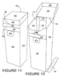
- the closed, completed carton 218 is shown in Figure 11 .
- the user need simply pull the access strip 184, tearing along the lines of perforation 186, 188.
- the access structure 148 can be hinged about the fold line 152 to open the carton 218, as shown in Figure 12 .
- the free end 210 of the strap 206 is pulled either outwardly or downwardly, shortening the portion of the strap 206 within the carton 218, causing the strap 206 to lift the articles 220 into easy reach, as shown in Figure 13 .
- the brake 195 effects friction between itself and the first portion of strap 206, as well as between the first portion of the strap 206 and at least one of the cut lines 138, 142 of the first and second brake apertures 136, 140 and the second portion of the strap 206. This friction enables the strap 206 to bear the load of articles with no supplementary force from a user.
- the articles 220 may thus be held in a position above the base of the carton 218, such that the user may easily reach them.
- the size and shape of the panels may be adjusted to accommodate articles of differing size or shape.
- the brake mechanism may be deployed in other applications; the number; type shape size and arrangement of articles held within the cartons may take alternative forms to those shown herein.
- hinged connection should not be construed as necessarily referring to a single fold line only; indeed it is envisaged that hinged connection can be formed from one or more of the following, a short slit, a frangible line or a fold line without departing from the scope of the invention.
Landscapes
- Engineering & Computer Science (AREA)
- Mechanical Engineering (AREA)
- Cartons (AREA)
Abstract
Description
- The invention relates to a carton for accommodating one or more articles, for example bottles, which carton is provided with a dispensing structure for removal of the articles from the carton. The invention also relates to one or more blanks for the construction of a carton and to packages comprising a carton containing articles.
- A problem associated with the prior art is the difficulty a user faces when removing vertically aligned articles from a carton when the carton is stored upright.
- The present invention and its embodiments seek to overcome the problems of the prior art.
- According to a first aspect the invention provides a carton for containing a plurality of articles, the carton comprising a vertical dispensing structure for dispensing one or more articles through an upper aperture, the dispensing structure comprising a strap having a first end portion hingedly secured to a first wall of the carton and a having second free end of the strap, a portion of the strap between said first end and said second free end being positionable beneath a terminal article held within the carton such that pulling the second free end of the strap out of carton effects a dispensing of articles through the upper aperture.
- Preferably the first end portion of the strap is attached to a hinged flap which is struck from or connected to said first wall of the carton.
- Preferably the first end portion of the strap is attached to a hinged flap such that the first end portion of the strap is maintained in a substantially flat position during dispensing of articles.
- Preferably the strap is positioned to correspond with the centre of gravity of the terminal article. Preferably a brake is provided for applying a frictional force to the strap.
- Optionally a second wall opposed to said first wall comprises a brake aperture, wherein the brake presses a portion of the strap into the brake aperture to provide the frictional force, such that the strap is able to bear the weight of the terminal article.
- According to a second aspect the invention provides a package comprising: one or more articles and a carton comprising a vertical dispensing structure for dispensing one or more articles through an upper aperture, the dispensing structure comprising a strap having a first end portion hingedly secured to a first wall of the carton and a having second free end of the strap, a portion of the strap between said first end and said second free end being positionable beneath a terminal article held within the carton such that pulling the second free end of the strap out of carton effects a dispensing of articles through the upper aperture.
- According to a third aspect the invention provides a method of dispensing articles from a carton comprising a vertical dispensing structure for dispensing one or more articles through an upper aperture, the dispensing structure comprising a strap having a first end portion hingedly secured to a first wall of the carton and a having second free end of the strap, a portion of the strap between said first end and said second free end being positionable beneath a terminal article held within the carton; providing force to pull the the second free end of the strap upwardly out of carton thus lifting said vertical dispensing structure and said articles; and retrieving the uppermost article through said upper aperture.
- Preferably said carton further comprises a brake and wherein said method further comprises applying a frictional force to said strap through the use of said brake.
- According to a fourth aspect the invention provides for containing a plurality of articles, the carton comprising a vertical dispensing structure for dispensing one or more articles through an upper aperture, wherein the dispensing structure comprises an elongate member with a handle means at a distal end and a portion engageable with a terminal article contained therein and wherein the elongate member comprises an insert.
- Preferably a portion of the elongate member comprises at least one elevation panel, wherein, in use, a terminal article held therein rests on the elevation panel such that an upward force exerted on the elongate member raises the article for dispensing at the upper aperture and wherein the elevation panel is reinforced by a gusset portion attached at a first end of the elevation panel and at a second end to the elongate member.
- Embodiments of the present invention provide a carton for containing a plurality of articles, the carton comprising a vertical dispensing structure for dispensing one or more articles through an upper aperture.
- Preferably, the dispensing structure comprises an elongate member with a handle means at a distal end, and a portion engagable with a terminal article contained therein.
- Preferably, the dispensing structure comprises a first insert sized to fit within the carton. Preferably, the portion engagable with a terminal article comprises at least one elevation panel, wherein, in use, a terminal article contained in the carton rests on the elevation panel such that an upward force exerted on the handle raises the article for dispensing at the upper aperture. Preferably, the elevation panel is perpendicular to the handle.
- Preferably, the elevation panel is reinforced by a gusset portion attached at a first end to the elevation panel and at a second end to the handle panel.
- Preferably, the insert is adapted and arranged to be folded flat, for ease of transport.
- In another embodiment, the dispensing structure comprises a strap attached at, or proximate, a second end thereof to a side panel of the carton, such that the strap may extend beneath a terminal article held therein to present the distal end over or through an opposing side panel, wherein a pull force exerted upon the distal end effects a dispensing of particles through the upper aperture.
- Preferably the second end of the strap is attached to a hinged flap which is struck from or connected to the side panel, wherein the hinged flap aids optimal alignment of the strap beneath articles held within the carton.
- Preferably the strap is positioned to correspond with the centre of gravity of articles held within the carton.
- Preferably, the carton further comprises a brake for applying a frictional force to the elongate member. Preferably, the opposing side panel comprises a brake aperture, wherein the brake presses a portion of the strap into the brake aperture to provide the frictional force, such that the strap is able to bear the weight of articles contained within the carton.
- Preferably, the carton is sized to fit within the door compartment of a domestic refrigerator.
- In another aspect, the invention comprises one or more blanks for constructing the embodiments described herein.
- In another aspect, the invention relates to a package comprising: a carton for containing a plurality of articles, the carton comprising a vertical dispensing structure for dispensing one or more articles through an upper aperture; and, one or more articles held within the carton.
-
-
Figure 1 shows a first blank for the construction of a carton according to the present invention. -
Figures 2, 2A and 2B show a blank for the construction of a vertical dispensing structure, and a vertical dispensing structure. -
Figures 3 and 3A show a carton and a vertical dispensing means.Figure 4 shows a vertical dispensing structure being placed inside a carton.Figure 5 shows a completed carton according to the present invention. -
Figure 6 shows a carton according to the present invention dispensing articles.Figure 7 shows a blank for a carton according to the present invention.Figure 8 shows steps in the construction of a carton according to the present invention from a blank.Figure 9 shows a carton, according to the present invention, loaded with vertically aligned articles. -
Figure 10 shows a carton, according to the present invention, loaded with vertically aligned articles. -
Figure 11 shows a closed carton according to the present invention.Figure 12 shows an open carton according to the present invention. -
Figure 13 shows a carton according to the present invention dispensing articles. - Referring to the drawings, there is shown a carton and a blank for forming a carton. The blank and carton are formed in paperboard or other foldable sheet material, for example plastic and the like, to which has been added cut and fold lines. The cartons are used to house one or more articles, for example bottles, and to dispense the articles through an upper aperture, the upper aperture positioned at or towards the intended upper surface of the carton.
- Referring to
Figure 1 , there is shown a first blank 10 for forming a carton. The first blank comprises afirst side panel 12, asecond side panel 14, athird side panel 16 and afourth side panel 18 hingedly connected in series along thefold lines securing flap 26 hingedly attached to thefirst side panel 12 along thefold line 27. - A first
end wall structure 28 is provided by firstend wall panels fourth side panels minor flaps third side panels access structure 38 is provided byaccess panels fourth side panels access flaps third side panels access panels curved cut lines curved cut lines fold line 23a. Thecurved cut lines fold line 23b. A line ofperforation 25a joins thecurved cut 21a to the intersection of thefolds perforation 25b joins thecurved cut 21b to the intersection of thefolds perforation 25c joins thecurved cut 21c to the intersection of thefolds perforation 25d joins thecurved cut 21d to the intersection of the fold 23 and theouter edge 29 of thefourth side panel 18. -
Optional apertures 44 may be provided through one or more of theside panels aperture 44 may be closed by a transparent material. - One further embodiment of the present invention is apparent through the Figures identified above and is a method of dispensing articles, said method comprising: providing a carton comprising one or more articles contained therein, a vertical dispensing structure having an elongate member said elongate member comprising a first distal end and a second end engageable with a terminal article, and an upper aperture; providing force to said elongate member to effect the upward movement of said vertical dispensing structure and said articles; and retrieving the uppermost article through said upper aperture. Each of the features of the embodiments of the carton(s) and package(s) identified above and below may be incorporated into the method of dispensing articles disclosed thus, allowing for various embodiments of the method of dispensing articles.
- Referring now to
Figures 2, 2A and 2B , avertical dispensing insert 51 is provided by a second blank. Afirst handle panel 50 is hingedly attached to anelevation panel 52a along afold line 54a. Elevation flaps 56a, 56b are further hingedly attached to theelevation panel 52a along thefold lines cut lines cut lines fold lines - Gusset flaps 62a, 62b are hingedly attached to the sides of the
handle panel 50 along thefold lines cut lines cut lines fold line 54a. The gusset flaps 62a, 62b are divided intogusset sides gusset closure tabs fold lines fold lines cut lines - Optionally, a
handle aperture 76a may be formed in thehandle panel 50. Preferably, thehandle 76a comprises acut line 78 which forms all but one side of a planar shape. The final side of this planar shape comprises afold line 80, to define ahandle flap 82. - In a preferred embodiment, a
second handle panel 84 is hingedly attached to thefirst handle panel 50 along afold line 86. The second handle panel is preferably a mirror image of thefirst handle panel 50, being hingedly attached to corresponding gusset flaps 62c, 62d and anelevation panel 52b. Theelevation panel 52b being, in turn, hingedly attached toelevation flaps fold line 86. - In order to form the completed carton in flat collapsed condition from the blanks, a simple folding and gluing procedure is required. The folding and gluing operations can be performed in one or more straight-line machines, so that the carton is not required to be rotated or inverted to complete its construction. The folding process is not limited to that described below and can be altered according to particular manufacturing requirements.
- In formation of the flat carton from the first blank 10, the securing
flap 26 is folded inwardly along thefold line 27. Preferably, glue or some other securing means is provided along the securingflap 26. Glue or other securing means may also be provided along the outer edge of thefourth side panel 18. The first blank 10 is then folded along thefold line 22 to bring thefourth side panel 18 into face contacting arrangement with the securingflap 26, to provide a tubular structure, and is secured thereto by the glue or other such securing means as used. Thus, the carton is in a flat collapsed form ready to be supplied to an end user or converting plant for loading, or to move on to the next stage of the construction and erecting process. - In construction of the dispensing means 51 from the second blank, the
first handle panel 50 andsecond handle panel 84 are folded along thefold line 86 to effect a back-to-back formation. Glue may have been applied to points on the rear of one or each of the first andsecond handle panels elevation panel 52a is then folded outwardly along thefold line 54a. The elevation flaps 56a, 56b are also folded outwardly along thefold lines fold tines gusset closure tabs gusset closure tabs elevation panel 52a in a position substantially perpendicular to thefirst handle panel 50, supported by thegusset structure 88a. The process is then repeated to thesecure elevation panel 52b in a position perpendicular to thesecond handle panel 84, supported by thegusset structure 88b. - For ease of packing and transit before use, the
gusset structures fold lines elevation panels handle panels - In constructing the ends of the
carton 90, the first end flaps 34, 36 are folded inwardly along the fold lines 35, 37 respectively, and glue or some other securing means is provided along the first end flaps 34, 36. Thefirst end panels first end panels first end panels -
Figure 3 shows thecarton 90, with theaccess structure 38 open, ready for loading.Figure 3A shows the completed dispensinginsert 51. The dispensinginsert 51 fits snugly inside thecarton 90 and as such is placed inside in a rest position, with theelevation panels carton 90 and thehandle panels Figure 4 , prior to loading. Articles may then be vertically aligned either side of thehandle panels access structure 38 is closed by folding the access flaps 46, 48 inwardly along the fold lines 47, 49 respectively. Glue is then provided on theaccess panels perforation access panels carton 90 closed. A closed, completed carton is shown inFigure 5 . - To gain access to the
carton 90 through theaccess structure 38, the user punctures through theaccess tabs access panels access panels perforation access panels access panels flaps - To retrieve articles from
carton 90, the user simply grips the dispensing means 51 and lifts, until such a time as the desired article can be easily retrieved, as demonstrated inFigure 6 . After retrieval, the user simply lowers the dispensing means 51 back to its rest position. - In some embodiments, the carton comprises a brake (not shown) for providing a frictional force to the dispensing insert. For example, in the event that the insert is dropped inside the carton, while carrying a load of articles, the frictional force provided by the brake will slow or stop the fall of the insert such that the articles are not damaged, and/or the carton is not punctured.
- A further embodiment of the invention is shown in
Figures 7 - 13 . The invention relates to a carton constructed from a blank 99. - Referring to
Figure 7 , a blank 99 comprises afirst side panel 100, asecond side panel 102, athird side panel 104, afourth side panel 106 and anaccess structure 148, hingedly connected in series alongfold lines flap 118 is hingedly attached to thefirst side panel 100. - A pair of
first end panels second side panel 102 andfourth side panel 106 respectively, alongfold lines first side panel 100 and thethird side panel 104 respectively, alongfold lines - Preferably, the
second side panel 102 comprises afirst brake aperture 136, defined by acut line 138. Hingedly attached to thesecond side panel 102, along afold line 146 is a secondbrake aperture panel 144. The secondbrake aperture panel 144 comprises asecond brake aperture 140, which is defined by acut line 142. Thesecond brake aperture 140 is preferably positioned in the secondbrake aperture panel 144 such that when the secondbrake aperture panel 144 is folded inwardly along thefold line 146 into face contact arrangement with thesecond side panel 102, thesecond brake aperture 140 directly superposes thefirst brake aperture 136. Preferably, thefold line 146 does not span the full width of thesecond side panel 102 and the secondbrake aperture panel 144. Instead, the remainder of the boundary of thesecond side panel 102 and the secondbrake aperture panel 144 comprises cutlines brake aperture panel 144 and thesecond side panel 102. Thefold line 146 preferably defines the extremity of the male section of the secondbrake aperture panel 144. - Preferably, the
second side panel 102 is shorter in length than its opposingfourth side panel 106. The difference in length between thesecond side panel 102 and thefourth side panel 106 is compensated in thefirst side panel 100 and thesecond side panel 104 by way of their trapezoidal shapes. - The
access structure 148 preferably comprises anaccess panel 150 which adjoins thefourth side panel 106 along afold line 152. Side access flaps 154, 156 are hingedly connected to theaccess panel 150 alongfold lines front access flap 158 is hingedly attached to theaccess panel 150 along afold line 168 and is further defined byfold lines perforation 188. Access securing flaps 160, 162 are hingedly attached to thefront access flap 158 alongfold lines access strip 184 is attached to thefront access flap 158 along a line ofperforation 188, and in turn is attached to anaccess closure strip 190 along a line ofperforation 186. - A
brake 195 is hingedly connected to the access closure strip along afold line 200. Thefold line 200 preferably does not span the entire width of theaccess closure strip 190, instead, theaccess closure strip 190 is further defined bycut lines - The
brake 195 is preferably divided into three byfold lines central brake portion 192, afirst brake flap 194 and asecond brake flap 196. Thecentral brake portion 192, thefirst brake flap 194 and thesecond brake flap 196 are preferably substantially equal in width. - A
hinge panel 174 is preferably hingedly attached to thefourth side panel 106 along afold line 178. Thehinge panel 174 preferably comprises atop edge 175, which is preferably aligned with thefold line 152, and ahinge flap 176, which is defined by acut line 182 and afold line 180. Thehinge panel 174 is so dimensioned that when it is folded inwardly to be in face contact arrangement with thefourth side panel 106, thehinge flap 176 is substantially aligned with thecentral brake portion 192. - Further provided is a
strap 206, which is preferably more than twice as long as thefourth side panel 106 andstrap tab 212, for being received on afree end 210 ofstrap 206. Thestrap tab 212 preferably comprises a pair oftab panels fold line 216. - In order to form the completed carton in flat, collapsed condition from the blank, a series of sequential folding and gluing operations are required and will be described further with special reference to
Figure 8 of the drawings. The folding and gluing operations can be performed in one or more straight line machines, so that the carton is not required to be rotated or inverted to complete its construction. The folding process is not limited to that described below and can be altered according to particular manufacturing requirements. - Referring to
Figure 8 , glue or other such securing means is applied to the secondbrake aperture panel 144. The secondbrake aperture panel 144 is then folded inwardly about thefold line 146 and secured in face contact arrangement with thesecond side panel 102, such that thefirst brake aperture 136 is directly superposed by thesecond brake aperture 140. - In a further step, glue is applied to a
first end 208 of thestrap 206. Thefirst end 208 of thestrap 206 is then secured to thehinge flap 176 such that the remainder of thestrap 206 leads away from thefold line 180 and is substantially parallel to theedge 116 of thefourth side panel 106. Glue is then applied to the area of thehinge panel 174 not comprising thehinge flap 176. Thehinge panel 174 is folded inwardly about thefold line 178 and secured in face contact arrangement with thefourth side panel 106, such that thehinge flap 176 and thus thestrap 206 may hinge away from thefourth side panel 106 about thefold line 180. In this way when thestrap 206 is deployed to dispense articles from the carton, thehinge flap 176 anchors thefirst end 208 of thestrap 206 albeit in a flexible manner. Whereas thefirst end 208 of thestrap 206 is held securely, by virtue of being connected to thehinge flap 176, and therefore its position within the carton relative to the articles is maintained during use of thestrap 206 for dispensing article, because the hinge flap is foldable aboutfold line 180, the angle of thestrap 206 can be changed if required. In other words, thehinge flap 176 secures thefirst end 208 of thestrap 206 in order to prevent it from being pulled down the longitudinal axis of thefourth side panel 106 or pulled loose or pulled under the articles and thus rendering the dispenser useless; yet at the same time allows for some movement of thefirst end 208strap 206 away from and out of the plane of thefourth side panel 106. Additionally, because thefirst end 208 of thestrap 206 is positioned onhinge panel 176 and hingepanel 176 is folded to be disposed substantially centrally of thefourth side panel 106, thestrap 206 is maintained in a substantially central location for facilitating balanced dispensing of the articles and restricts thestrap 206 from twisting. These features facilitate balanced dispensing of the articles. Preferably, theother end 210 of thestrap 206 is positioned such that it is aligned oppositely to thefirst sned 208 ofstrap 206, this further facilitates balanced dispensing of the articles and restricts thestrap 206 from twisting. - In a further step, the
first brake flap 194 is folded inwardly about thefold line 204 to be in face contact arrangement with thecentral brake portion 192. Glue is applied to the rear of thefirst brake flap 194 and thesecond brake flap 196 is folded inwardly about thefold line 202 and secured in face contact arrangement with the rear of thefirst brake flap 194. Glue is then applied to the rear of thesecond brake flap 196 and thecomplete brake 192 is folded inwardly about thefold line 202 to be secured in face contact arrangement with theaccess closure strip 190. - In a further step, the securing
flap 118 is folded inwardly about thefold line 114 and glue is applied along its rear. The blank 99 is folded about thefold line 110 to secure the rear of the securingflap 118 in face contact arrangement with thefourth face panel 106 along itsedge 116, providing a tubular structure. Finally, glue is applied to thetab panels Free end 210 of thestrap 206 is secured onto one of thetab panels 214a before the other of the tab panels is folded inwardly about thefold line 216 to secure thetab 212 to thestrap 206. Thus the carton is in a flat collapsed form, ready to be supplied to an end user for loading or to move onto the next stage of the construction process. - In erecting the carton, the first end flaps 120, 126 are folded inwardly along the
fold lines first end panels fold lines first end panels - The
access structure 148 is completed first by folding thefront access flap 158 inwardly along thefold line 168. Theaccess securing flaps fold lines access securing flaps fold lines access securing flaps access panel 150 and thefront access flap 158. Theaccess structure 184 may be hinged along thefold line 152 to provide a removable cover for the carton. - Before loading the
carton 218, thestrap 206 is placed to rest across thefold line 146.Articles 220 are then loaded into the carton in vertical alignment, such that the strap extends downwardly from thehinge flap 176, along the base of thecarton 218 and upwardly such that thefree end 210 may rest over thefold line 146 and hang outside the carton with thetab 212 beneath thefirst brake aperture 136, as shown inFigures 9 and 10 . - The
carton 218 is sealed by applying strips of glue G to theaccess closure strip 190, either side of thebrake 195, as shown inFigure 10 . Theaccess structure 148 is then closed and theaccess closure strip 190 secured in face contact arrangement with the outside of thesecond side panel 102, such that thebrake 195 pushes a portion of thestrap 206 through thefirst brake aperture 136, preferably to contact a second portion of thestrap 206. Thetab 212 extends below theaccess closure strip 190. The closed, completedcarton 218 is shown inFigure 11 . - To gain access to the
carton 218, the user need simply pull theaccess strip 184, tearing along the lines ofperforation access strip 184 is removed, theaccess structure 148 can be hinged about thefold line 152 to open thecarton 218, as shown inFigure 12 . - To dispense
articles 220 from thecarton 218, thefree end 210 of thestrap 206 is pulled either outwardly or downwardly, shortening the portion of thestrap 206 within thecarton 218, causing thestrap 206 to lift thearticles 220 into easy reach, as shown inFigure 13 . - The
brake 195 effects friction between itself and the first portion ofstrap 206, as well as between the first portion of thestrap 206 and at least one of the cut lines 138, 142 of the first andsecond brake apertures strap 206. This friction enables thestrap 206 to bear the load of articles with no supplementary force from a user. Thearticles 220 may thus be held in a position above the base of thecarton 218, such that the user may easily reach them. - It can be appreciated that various changes may be made within the scope of the present invention, for example, the size and shape of the panels may be adjusted to accommodate articles of differing size or shape. The brake mechanism may be deployed in other applications; the number; type shape size and arrangement of articles held within the cartons may take alternative forms to those shown herein.
- It will be recognised that as used herein, directional references such as "top", "bottom", "front", "back", "end", "side", "inner", "outer", "upper" and "lower" do not limit the respective panels to such orientation, but merely serve to distinguish these panels from one another. Any reference to hinged connection should not be construed as necessarily referring to a single fold line only; indeed it is envisaged that hinged connection can be formed from one or more of the following, a short slit, a frangible line or a fold line without departing from the scope of the invention.
Claims (14)
- A carton for containing a plurality of articles, the carton comprising a vertical dispensing structure for dispensing one or more articles through an upper aperture, the dispensing structure comprising a strap having a first end portion hingedly secured to a first wall of the carton and a having second free end of the strap, a portion of the strap between said first end and said second free end being positionable beneath a terminal article held within the carton such that pulling the second free end of the strap out of carton effects a dispensing of articles through the upper aperture.
- A carton according to Claim 1, wherein the first end portion of the strap is attached to a hinged flap which is struck from or connected to said first wall of the carton.
- A carton according to claim 2 wherein the first end portion of the strap is attached to a hinged flap such that the first end portion of the strap is maintained in a substantially flat position during dispensing of articles.
- A carton according to any of claims 1 to 3, wherein the strap is positioned to correspond with the centre of gravity of the terminal article.
- A carton according to any preceding claim, wherein the carton further comprises a brake for applying a frictional force to the strap.
- A carton according to Claim 5, wherein a second wall opposed to said first wall comprises a brake aperture, wherein the brake presses a portion of the strap into the brake aperture to provide the frictional force, such that the strap is able to bear the weight of the terminal article.
- One or more blanks for constructing a carton according to any preceding claim.
- A package comprising: one or more articles and a carton comprising a vertical dispensing structure for dispensing one or more articles through an upper aperture, the dispensing structure comprising a strap having a first end portion hingedly secured to a first wall of the carton and a having second free end of the strap, a portion of the strap between said first end and said second free end being positionable beneath a terminal article held within the carton such that pulling the second free end of the strap out of carton effects a dispensing of articles through the upper aperture.
- A method of dispensing articles from a carton comprising a vertical dispensing structure for dispensing one or more articles through an upper aperture, the dispensing structure comprising a strap having a first end portion hingedly secured to a first wall of the carton and a having second free end of the strap, a portion of the strap between said first end and said second free end being positionable beneath a terminal article held within the carton; providing force to pull the the second free end of the strap upwardly out of carton thus lifting said vertical dispensing structure and said articles; and retrieving the uppermost article through said upper aperture.
- The method of claim 9 wherein said carton further comprises a brake and wherein said method further comprises applying a frictional force to said strap through the use of said brake.
- A carton for containing a plurality of articles, the carton comprising a vertical dispensing structure for dispensing one or more articles through an upper aperture, wherein the dispensing structure comprises an elongate member with a handle means at a distal end and a portion engageable with a terminal article contained therein and wherein the elongate member comprises an insert.
- A carton according to Claim 11, wherein a portion of the elongate member comprises at least one elevation panel, wherein, in use, a terminal article held therein rests on the elevation panel such that an upward force exerted on the elongate member raises the article for dispensing at the upper aperture and wherein the elevation panel is reinforced by a gusset portion attached at a first end of the elevation panel and at a second end to the elongate member.
- A package comprising one or more articles and a carton according to any of claims 11 or 12.
- One or more blanks for forming a carton according to any of claims 11 or 12.
Applications Claiming Priority (1)
| Application Number | Priority Date | Filing Date | Title |
|---|---|---|---|
| GBGB0715900.7A GB0715900D0 (en) | 2007-08-15 | 2007-08-15 | Carton and blanks for carton |
Publications (2)
| Publication Number | Publication Date |
|---|---|
| EP2025609A2 true EP2025609A2 (en) | 2009-02-18 |
| EP2025609A3 EP2025609A3 (en) | 2009-05-13 |
Family
ID=38566420
Family Applications (1)
| Application Number | Title | Priority Date | Filing Date |
|---|---|---|---|
| EP08162446A Withdrawn EP2025609A3 (en) | 2007-08-15 | 2008-08-14 | Carton, blanks for forming a carton, package and method of dispensing articles from a carton |
Country Status (3)
| Country | Link |
|---|---|
| EP (1) | EP2025609A3 (en) |
| GB (1) | GB0715900D0 (en) |
| RU (1) | RU2008133650A (en) |
Cited By (5)
| Publication number | Priority date | Publication date | Assignee | Title |
|---|---|---|---|---|
| GB2500822A (en) * | 2012-03-29 | 2013-10-02 | Andrew Phillips | Container and Method of Packaging Goods |
| JP2015000764A (en) * | 2013-06-14 | 2015-01-05 | 圭佑 西田 | Package-contents mutual adhesion preventive take-out segmentation film sheet |
| FR3037568A1 (en) * | 2015-06-16 | 2016-12-23 | Eric Prades | CONTAINER FOR CONTAINING RIGID CONTENT, INTEGRATING A CONTENT EXTRACTION SYSTEM |
| WO2025042336A1 (en) * | 2023-08-23 | 2025-02-27 | Golden Wheel Industries Pte Ltd | Slider packaging structure |
| WO2026087779A1 (en) * | 2024-10-25 | 2026-04-30 | Philip Morris Products S.A. | Container having a locking panel |
Citations (2)
| Publication number | Priority date | Publication date | Assignee | Title |
|---|---|---|---|---|
| US2997163A (en) | 1959-08-26 | 1961-08-22 | Tel-Wardi Mayer | Packing containers |
| WO2001034003A1 (en) | 1999-11-11 | 2001-05-17 | Yossi Ben | A food holder having a flexible strip |
Family Cites Families (2)
| Publication number | Priority date | Publication date | Assignee | Title |
|---|---|---|---|---|
| CH690363A5 (en) * | 1995-08-09 | 2000-08-15 | Soremartec Sa | Container for products such as pastilles and the like. |
| DE29813168U1 (en) * | 1998-07-24 | 1998-11-26 | Schmitt, Kurt, 67373 Dudenhofen | Food intake with transport or pull tab |
-
2007
- 2007-08-15 GB GBGB0715900.7A patent/GB0715900D0/en not_active Ceased
-
2008
- 2008-08-14 EP EP08162446A patent/EP2025609A3/en not_active Withdrawn
- 2008-08-15 RU RU2008133650/12A patent/RU2008133650A/en not_active Application Discontinuation
Patent Citations (2)
| Publication number | Priority date | Publication date | Assignee | Title |
|---|---|---|---|---|
| US2997163A (en) | 1959-08-26 | 1961-08-22 | Tel-Wardi Mayer | Packing containers |
| WO2001034003A1 (en) | 1999-11-11 | 2001-05-17 | Yossi Ben | A food holder having a flexible strip |
Cited By (7)
| Publication number | Priority date | Publication date | Assignee | Title |
|---|---|---|---|---|
| GB2500822A (en) * | 2012-03-29 | 2013-10-02 | Andrew Phillips | Container and Method of Packaging Goods |
| WO2013144635A2 (en) | 2012-03-29 | 2013-10-03 | Andrew Phillips | A container and method of packaging goods |
| JP2015000764A (en) * | 2013-06-14 | 2015-01-05 | 圭佑 西田 | Package-contents mutual adhesion preventive take-out segmentation film sheet |
| FR3037568A1 (en) * | 2015-06-16 | 2016-12-23 | Eric Prades | CONTAINER FOR CONTAINING RIGID CONTENT, INTEGRATING A CONTENT EXTRACTION SYSTEM |
| FR3037567A1 (en) * | 2015-06-16 | 2016-12-23 | Eric Prades | <P> TRANSLATION EXTRACTION SYSTEM (S.E.T) </ P> |
| WO2025042336A1 (en) * | 2023-08-23 | 2025-02-27 | Golden Wheel Industries Pte Ltd | Slider packaging structure |
| WO2026087779A1 (en) * | 2024-10-25 | 2026-04-30 | Philip Morris Products S.A. | Container having a locking panel |
Also Published As
| Publication number | Publication date |
|---|---|
| GB0715900D0 (en) | 2007-09-26 |
| EP2025609A3 (en) | 2009-05-13 |
| RU2008133650A (en) | 2010-02-20 |
Similar Documents
| Publication | Publication Date | Title |
|---|---|---|
| EP1615839B1 (en) | Improved dispensing system for double stack carton | |
| EP1713701B1 (en) | Carton with an interlocking separator pad | |
| US7168558B2 (en) | Carton with an interlocking divider pad | |
| JP4994037B2 (en) | Display / Carton for sale | |
| US5427306A (en) | Reinforced bulk material box | |
| US20040188300A1 (en) | Can dispensing package | |
| US20070114151A1 (en) | Carton with dispensing feature for cans | |
| US20040188509A1 (en) | Carton with dispenser | |
| US20040074954A1 (en) | Carton with a dispenser in the top panel for dispensing pouches | |
| EP1751014B1 (en) | Retail dispensing and display carton | |
| US20070090175A1 (en) | Carton with opening access feature | |
| US20130181042A1 (en) | Carton and carton blank | |
| US7568611B2 (en) | Carton having stacking strength-enhancing feature | |
| US7614543B1 (en) | Carton with gravity feed dispenser | |
| EP1866213B1 (en) | Carton with dispensing feature | |
| WO2006047736A2 (en) | Dispensing carton | |
| CN101119905A (en) | Cardboard box with dispensing features for cans |
Legal Events
| Date | Code | Title | Description |
|---|---|---|---|
| PUAI | Public reference made under article 153(3) epc to a published international application that has entered the european phase |
Free format text: ORIGINAL CODE: 0009012 |
|
| AK | Designated contracting states |
Kind code of ref document: A2 Designated state(s): AT BE BG CH CY CZ DE DK EE ES FI FR GB GR HR HU IE IS IT LI LT LU LV MC MT NL NO PL PT RO SE SI SK TR |
|
| AX | Request for extension of the european patent |
Extension state: AL BA MK RS |
|
| PUAL | Search report despatched |
Free format text: ORIGINAL CODE: 0009013 |
|
| AK | Designated contracting states |
Kind code of ref document: A3 Designated state(s): AT BE BG CH CY CZ DE DK EE ES FI FR GB GR HR HU IE IS IT LI LT LU LV MC MT NL NO PL PT RO SE SI SK TR |
|
| AX | Request for extension of the european patent |
Extension state: AL BA MK RS |
|
| 17Q | First examination report despatched |
Effective date: 20090918 |
|
| 17P | Request for examination filed |
Effective date: 20090820 |
|
| AKX | Designation fees paid |
Designated state(s): AT BE BG CH CY CZ DE DK EE ES FI FR GB GR HR HU IE IS IT LI LT LU LV MC MT NL NO PL PT RO SE SI SK TR |
|
| RAP1 | Party data changed (applicant data changed or rights of an application transferred) |
Owner name: MEADWESTVACO PACKAGING SYSTEMS LLC |
|
| RAP1 | Party data changed (applicant data changed or rights of an application transferred) |
Owner name: MEADWESTVACO PACKAGING SYSTEMS, LLC |
|
| STAA | Information on the status of an ep patent application or granted ep patent |
Free format text: STATUS: THE APPLICATION IS DEEMED TO BE WITHDRAWN |
|
| 18D | Application deemed to be withdrawn |
Effective date: 20111115 |