EP2025608A2 - Carton and blank therefor - Google Patents
Carton and blank therefor Download PDFInfo
- Publication number
- EP2025608A2 EP2025608A2 EP08162444A EP08162444A EP2025608A2 EP 2025608 A2 EP2025608 A2 EP 2025608A2 EP 08162444 A EP08162444 A EP 08162444A EP 08162444 A EP08162444 A EP 08162444A EP 2025608 A2 EP2025608 A2 EP 2025608A2
- Authority
- EP
- European Patent Office
- Prior art keywords
- panel
- carton
- insert
- wrap around
- Prior art date
- Legal status (The legal status is an assumption and is not a legal conclusion. Google has not performed a legal analysis and makes no representation as to the accuracy of the status listed.)
- Withdrawn
Links
Images






Classifications
-
- B—PERFORMING OPERATIONS; TRANSPORTING
- B65—CONVEYING; PACKING; STORING; HANDLING THIN OR FILAMENTARY MATERIAL
- B65D—CONTAINERS FOR STORAGE OR TRANSPORT OF ARTICLES OR MATERIALS, e.g. BAGS, BARRELS, BOTTLES, BOXES, CANS, CARTONS, CRATES, DRUMS, JARS, TANKS, HOPPERS, FORWARDING CONTAINERS; ACCESSORIES, CLOSURES, OR FITTINGS THEREFOR; PACKAGING ELEMENTS; PACKAGES
- B65D5/00—Rigid or semi-rigid containers of polygonal cross-section, e.g. boxes, cartons or trays, formed by folding or erecting one or more blanks made of paper
- B65D5/42—Details of containers or of foldable or erectable container blanks
- B65D5/4212—Information or decoration elements, e.g. content indicators, or for mailing
- B65D5/4233—Cards, coupons, labels or the like formed separately from the container or lid
- B65D5/4237—Cards, coupons, labels or the like formed separately from the container or lid located in a compartment formed by a container wall and additional panel or panels formed integrally with the container
-
- B—PERFORMING OPERATIONS; TRANSPORTING
- B65—CONVEYING; PACKING; STORING; HANDLING THIN OR FILAMENTARY MATERIAL
- B65D—CONTAINERS FOR STORAGE OR TRANSPORT OF ARTICLES OR MATERIALS, e.g. BAGS, BARRELS, BOTTLES, BOXES, CANS, CARTONS, CRATES, DRUMS, JARS, TANKS, HOPPERS, FORWARDING CONTAINERS; ACCESSORIES, CLOSURES, OR FITTINGS THEREFOR; PACKAGING ELEMENTS; PACKAGES
- B65D71/00—Bundles of articles held together by packaging elements for convenience of storage or transport, e.g. portable segregating carrier for plural receptacles such as beer cans or pop bottles; Bales of material
- B65D71/06—Packaging elements holding or encircling completely or almost completely the bundle of articles, e.g. wrappers
- B65D71/12—Packaging elements holding or encircling completely or almost completely the bundle of articles, e.g. wrappers the packaging elements, e.g. wrappers being formed by folding a single blank
- B65D71/14—Packaging elements holding or encircling completely or almost completely the bundle of articles, e.g. wrappers the packaging elements, e.g. wrappers being formed by folding a single blank having the shape of a tube, without, or not being characterised by, end walls
-
- B—PERFORMING OPERATIONS; TRANSPORTING
- B65—CONVEYING; PACKING; STORING; HANDLING THIN OR FILAMENTARY MATERIAL
- B65D—CONTAINERS FOR STORAGE OR TRANSPORT OF ARTICLES OR MATERIALS, e.g. BAGS, BARRELS, BOTTLES, BOXES, CANS, CARTONS, CRATES, DRUMS, JARS, TANKS, HOPPERS, FORWARDING CONTAINERS; ACCESSORIES, CLOSURES, OR FITTINGS THEREFOR; PACKAGING ELEMENTS; PACKAGES
- B65D2571/00—Bundles of articles held together by packaging elements for convenience of storage or transport, e.g. portable segregating carrier for plural receptacles such as beer cans, pop bottles; Bales of material
- B65D2571/00123—Bundling wrappers or trays
- B65D2571/00129—Wrapper locking means
- B65D2571/00135—Wrapper locking means integral with the wrapper
- B65D2571/00141—Wrapper locking means integral with the wrapper glued
-
- B—PERFORMING OPERATIONS; TRANSPORTING
- B65—CONVEYING; PACKING; STORING; HANDLING THIN OR FILAMENTARY MATERIAL
- B65D—CONTAINERS FOR STORAGE OR TRANSPORT OF ARTICLES OR MATERIALS, e.g. BAGS, BARRELS, BOTTLES, BOXES, CANS, CARTONS, CRATES, DRUMS, JARS, TANKS, HOPPERS, FORWARDING CONTAINERS; ACCESSORIES, CLOSURES, OR FITTINGS THEREFOR; PACKAGING ELEMENTS; PACKAGES
- B65D2571/00—Bundles of articles held together by packaging elements for convenience of storage or transport, e.g. portable segregating carrier for plural receptacles such as beer cans, pop bottles; Bales of material
- B65D2571/00123—Bundling wrappers or trays
- B65D2571/00246—Locating elements for the contents
- B65D2571/00253—Locating elements for the contents integral with the wrapper
- B65D2571/00277—Slits or openings formed along a fold line
-
- B—PERFORMING OPERATIONS; TRANSPORTING
- B65—CONVEYING; PACKING; STORING; HANDLING THIN OR FILAMENTARY MATERIAL
- B65D—CONTAINERS FOR STORAGE OR TRANSPORT OF ARTICLES OR MATERIALS, e.g. BAGS, BARRELS, BOTTLES, BOXES, CANS, CARTONS, CRATES, DRUMS, JARS, TANKS, HOPPERS, FORWARDING CONTAINERS; ACCESSORIES, CLOSURES, OR FITTINGS THEREFOR; PACKAGING ELEMENTS; PACKAGES
- B65D2571/00—Bundles of articles held together by packaging elements for convenience of storage or transport, e.g. portable segregating carrier for plural receptacles such as beer cans, pop bottles; Bales of material
- B65D2571/00123—Bundling wrappers or trays
- B65D2571/00555—Wrapper opening devices
- B65D2571/00561—Lines of weakness
- B65D2571/00567—Lines of weakness defining a narrow removable strip
-
- B—PERFORMING OPERATIONS; TRANSPORTING
- B65—CONVEYING; PACKING; STORING; HANDLING THIN OR FILAMENTARY MATERIAL
- B65D—CONTAINERS FOR STORAGE OR TRANSPORT OF ARTICLES OR MATERIALS, e.g. BAGS, BARRELS, BOTTLES, BOXES, CANS, CARTONS, CRATES, DRUMS, JARS, TANKS, HOPPERS, FORWARDING CONTAINERS; ACCESSORIES, CLOSURES, OR FITTINGS THEREFOR; PACKAGING ELEMENTS; PACKAGES
- B65D2571/00—Bundles of articles held together by packaging elements for convenience of storage or transport, e.g. portable segregating carrier for plural receptacles such as beer cans, pop bottles; Bales of material
- B65D2571/00123—Bundling wrappers or trays
- B65D2571/00555—Wrapper opening devices
- B65D2571/00561—Lines of weakness
- B65D2571/00592—Lines of weakness with means for reclosing
-
- B—PERFORMING OPERATIONS; TRANSPORTING
- B65—CONVEYING; PACKING; STORING; HANDLING THIN OR FILAMENTARY MATERIAL
- B65D—CONTAINERS FOR STORAGE OR TRANSPORT OF ARTICLES OR MATERIALS, e.g. BAGS, BARRELS, BOTTLES, BOXES, CANS, CARTONS, CRATES, DRUMS, JARS, TANKS, HOPPERS, FORWARDING CONTAINERS; ACCESSORIES, CLOSURES, OR FITTINGS THEREFOR; PACKAGING ELEMENTS; PACKAGES
- B65D2571/00—Bundles of articles held together by packaging elements for convenience of storage or transport, e.g. portable segregating carrier for plural receptacles such as beer cans, pop bottles; Bales of material
- B65D2571/00123—Bundling wrappers or trays
- B65D2571/00648—Elements used to form the wrapper
- B65D2571/00654—Blanks
- B65D2571/0066—Blanks formed from one single sheet
-
- B—PERFORMING OPERATIONS; TRANSPORTING
- B65—CONVEYING; PACKING; STORING; HANDLING THIN OR FILAMENTARY MATERIAL
- B65D—CONTAINERS FOR STORAGE OR TRANSPORT OF ARTICLES OR MATERIALS, e.g. BAGS, BARRELS, BOTTLES, BOXES, CANS, CARTONS, CRATES, DRUMS, JARS, TANKS, HOPPERS, FORWARDING CONTAINERS; ACCESSORIES, CLOSURES, OR FITTINGS THEREFOR; PACKAGING ELEMENTS; PACKAGES
- B65D2571/00—Bundles of articles held together by packaging elements for convenience of storage or transport, e.g. portable segregating carrier for plural receptacles such as beer cans, pop bottles; Bales of material
- B65D2571/00123—Bundling wrappers or trays
- B65D2571/00709—Shape of the formed wrapper, i.e. shape of each formed element if the wrapper is made from more than one element
- B65D2571/00716—Shape of the formed wrapper, i.e. shape of each formed element if the wrapper is made from more than one element tubular without end walls
-
- B—PERFORMING OPERATIONS; TRANSPORTING
- B65—CONVEYING; PACKING; STORING; HANDLING THIN OR FILAMENTARY MATERIAL
- B65D—CONTAINERS FOR STORAGE OR TRANSPORT OF ARTICLES OR MATERIALS, e.g. BAGS, BARRELS, BOTTLES, BOXES, CANS, CARTONS, CRATES, DRUMS, JARS, TANKS, HOPPERS, FORWARDING CONTAINERS; ACCESSORIES, CLOSURES, OR FITTINGS THEREFOR; PACKAGING ELEMENTS; PACKAGES
- B65D2571/00—Bundles of articles held together by packaging elements for convenience of storage or transport, e.g. portable segregating carrier for plural receptacles such as beer cans, pop bottles; Bales of material
- B65D2571/00123—Bundling wrappers or trays
- B65D2571/00808—Inserts
- B65D2571/00827—Cards, coupons
Definitions
- the present invention relates generally to cartons and more specifically to cartons for receiving articles and promotional material.
- the invention is particularly, although not exclusively, concerned with wrap around cartons.
- One such strategy is to include promotional material, for example brochures or other printed material and/or CDs, in the package together with the goods being sold.
- promotional material for example brochures or other printed material and/or CDs
- a further such strategy is to use transparent packaging to allow the consumer to view goods to be sold.
- one drawback with this strategy is the reduction of printable coated surface for promotional purposes.
- a first aspect of the invention provides a carton for receiving articles, the carton comprising first and second side walls, a top wall and a bottom wall hingedly connected together to form a tubular structure and an insert associated with the tubular structure, at least one of the walls comprising a pair of inner and outer panels in overlying relationship to form a pocket therebetween, the insert being received in the pocket for sliding movement with respect to the tubular structure.
- the inner panel is hinged to the outer panel by hinge line.
- the carton is a wrap around carrier for wrapping about one or more articles.
- the insert is slidingly movable in a direction along a tubular axis of the tubular structure.
- the insert is slidingly movable between a retracted position where the insert is fully received in the pocket and an extended position where the insert is disposed outside the pocket except for an inner end portion of the insert.
- the insert further includes a main panel, the locking panel being hingedly connected to the main panel and folded into a face-contacting relationship with the main panel to cooperate with the abutment.
- the transparent or translucent wall comprises a foldable plastics sheet material.
- the opaque wall comprises a paperboard sheet material.
- the opaque wall comprises two overlying panels. More preferably, the two overlying panels are the inner and outer panels which form the pocket.
- the carton may comprise an insert, which insert may comprise an insert panel and the insert panel may have a coated surface.
- the carton wall and/or the insert may comprise an abutment, for example to limit the relative movement between the insert and the carton.
- the abutment may be provided by a locking panel, for example a folded portion of the insert panel and/or a folded portion of one or both of the overlying panels of the carton wall.
- the locking panel of the overlying panel or panels is preferably located within the pocket. More preferably, the abutment is provided by an insert locking panel of the insert panel which cooperates with a locking panel of one or both of the overlying panels.
- the insert may comprise a brochure or a compact disc, which may comprise an abutment.
- the overlying panels may comprise a cutout for accessing a portion of the insert.
- the cutout is along an open edge of the pocket, for example a semi-circular cutout extending from the open edge.
- the overlying panels may be releasably secured together, for example by releasable securing means such as a zipper or any other suitable arrangement.
- the zipper may comprise a removable panel, for example two removable panels, which may be removable to expose a tongue.
- the tongue cooperates with a slit in an opposed panel to provide a secondary lock.
- the releasable securing means may be arranged to provide access to the insert without providing access to articles contained, in use, in the carton.
- the carton may include a transparent or translucent panel, for example one or more transparent or translucent walls.
- the pocket may be substantially opaque and may comprise a coated inner surface.
- a second aspect of the invention provides a carton for receiving articles, the carton comprising first and second side walls, a top wall and a bottom wall hingedly connected together to form a tubular structure, at least one of the walls comprising a pocket for the location of an insert, wherein the pocket includes tamper evidence means and/or in a third aspect of the invention provides locking means for indicating removal of the insert from the pocket.
- the pocket may comprise a locking panel, the locking panel providing the tamper evidence means and/or the locking means.
- the carton may comprise an insert, wherein the insert includes an insert locking panel, the insert locking panel cooperating with an abutment of the pocket to provide the tamper evidence means.
- the abutment of the pocket may be provided by the locking panel.
- a fourth aspect of the invention provides a carton for receiving articles therein, the carton comprising a transparent or translucent wall and a substantially opaque wall, wherein the opaque wall comprises a coated surface which is visible, in use, through the transparent or translucent wall.
- the transparent or translucent wall may comprise a foldable plastics sheet material and/or the opaque wall may comprise a paperboard sheet material.
- the opaque wall may comprise two overlying panels, which may define a pocket therebetween forreceiving an insert.
- the overlying panels may be provided by a single blank folded back on itself.
- the coated inner surface may be provided by an inner surface of one of the panels.
- the carton forms a tubular structure when it is in an erected condition.
- the carton is a wraparound carton. Additionally or alternatively, the carton may be any other form of carton capable of receiving articles therein.
- Yet further aspects of the invention provide packages comprising a carton according to any one of the first, second, third or fourth aspects of the invention containing articles.
- FIG. 1 there is shown a carton blank 1 formed from paperboard and having a side wall securing panel 2, a first upper side panel 3, a first lower side panel 4, a base panel 5, a second lower side panel 6, a second upper side panel 7, an outer top panel 8, and an inner top panel 9 hinged together in series.
- the side wall securing panel 2 is rectangular in shape and is hinged to a longitudinal edge of the first upper side panel 3 along one of its longitudinal edges by fold line 21.
- the first upper side panel 3 is rectangular in shape and is hinged to the first lower side panel 4 along the other longitudinal edge thereof, opposite fold line 21, by a fold line 31.
- the first lower side panel 4 is hinged to the base panel 5 by a pair of fold lines 41a, 41b and the base panel 5 is hinged to the second lower side panel 6 along a pair of fold lines 51a, 51b.
- the base panel 5 is substantially rectangular in shape and includes a tab 50, 52 at the centre of each longitudinal edge thereof, one of each tab 50, 52 lying between each pair of fold lines 41a, 41b and 51a, 51b.
- Each of the lower side panels 4, 6 has a respective pair of legs 42a, 42b and 62a, 62b which define therebetween a respective aperture 44, 64.
- Each aperture 44, 64 has the shape of a semi-ellipsoid which extends from the outer edges of the adjacent tab 50, 52 of the base panel 5.
- the outer edges 46a, 46b of the first lower side panel 4 flare outwardly towards the first upper side panel 3 to fold line 31.
- the outer edges 66a, 66b of the second lower side panel 6 flare outwardly towards a longitudinal edge of the second upper side panel 7 to which the second lower side panel 6 is hinged along fold line 61.
- the second upper side panel 7 is rectangular in shape and in hinged to the outer top panel 8 along the other longitudinal edge thereof, opposite fold line 61, by a fold line
- the outer top panel 8 is rectangular with rounded corners and includes a first locking panel 82 and an aperture 84 which is circular in this embodiment.
- the outer top panel 8 is hinged to the first locking panel 82 by a fold line 85 which is orthogonal to fold line 71.
- Fold line 85 passes through the centre of the aperture 84, half of which is located within the outer top panel 8 and the other half of which is located in the first locking panel 82.
- the outer top panel 8 is hinged, along a longitudinal edge thereof opposite fold line 71, to a longitudinal edge of the inner top panel 9 by fold line 81.
- the inner top panel 8 is rectangular and includes an second locking panel 92, an aperture 94, a stop panel 96 and a top wall securing panel 98.
- the inner top panel 9 is hinged to the second locking panel 92 by a fold line 95 which is orthogonal to fold line 81. Fold line 95 passes through the centre of the aperture 84, which is circular in this embodiment.
- Half of the aperture 94 is located within the inner top panel 9 and the other half is located in the second locking panel 92.
- the stop panel 96 is trapezoidal in shape and is hinged along the longest of its longitudinal edges to the inner top panel 9 by a fold line 93.
- the top wall securing panel 98 is rectangular in shape and is hinged along one of its longitudinal edges to the inner top panel by a fold line 91.
- an insert blank 10 formed from paperboard and having an insert panel 11 and an insert locking panel 12.
- the insert panel 11 is rectangular in shape with a slit 16, which is primarily straight with curved ends.
- the insert panel 11 is hinged along one of its lateral edges to the insert locking panel 12 by a fold line 13.
- the insert locking panel 12 is trapezoidal in shape with curved lateral edges 14a, 14b and includes a locking tab 15 extending from its free edge.
- the longest of the longitudinal edges of the insert locking panel 12 is provided by the fold line 13.
- the insert locking panel 12 is folded F1 about fold line 13 and the locking tab 15 is inserted into the slit 16, thereby to retain the insert locking panel 12 in an overlying relationship with the insert panel 11, thus providing an erected insert 10.
- Glue G is then applied to upper portions of the first locking panel 82 and the second locking panel 92 as shown in Figure 4 .
- the second locking panel 92 is then folded about fold line 95, the first locking panel 82 is folded F3 about fold line 85 and the stop panel 96 is folded about fold line 93 as shown in Figure 5 .
- the second locking panel 92 and first locking panel 82 are therefore secured to the inner top panel 9 in a facing relationship.
- Glue G is then applied to the top wall securing panel 98 and the stop panel 96.
- the inner top panel 9 is then folded F5 about fold line 81 such that the top wall securing panel 98 is secured to the second upper side panel 7 and the stop panel 96 is secured to the outer top panel 8 in facing relationships.
- a pocket is defined between the outer top panel 8 and the inner top panel 9 with the first and second locking panels 82, 92 therein and facing one another and the top panel 96 defines a base of the pocket.
- fold lines 91 and 71 overlie one another and are arranged to allow the top panels 8, 9 to fold relative to the second upper side panel 7.
- the insert 10 is then orientated with the insert locking panel 12 lowermost as shown in Figure 7 and is inserted I between the outer and inner top panels 8, 9 (i.e. in the pocket).
- One or both major surfaces of the insert may be coated surfaces.
- first upper side panel 3 and side wall securing panel 2 are folded about fold lines 41a and 41b until fold line 31 abuts an adjacent edge of the flanges of the lower layer of articles A.
- the first upper side panel 3 and side wall securing panel 2 are then folded further about fold line 31 until fold line 21 abuts an adjacent edge of the flanges of the upper layer of articles A and the side wall securing panel 2 is then folded about fold line 21 to overlie the flanges of the upper layer of articles A.
- Glue (not shown) is then applied to the exposed surface of the side wall securing panel 2.
- the second lower side panel 6, second upper side panel 7 and overlying top panels 8, 9, with the insert 10 therebetween, are then folded about fold lines 51a, 51b until fold line 61 abuts an adjacent edge of the flanges of the lower layer of articles A.
- the second upper side panel 7 and overlying top panels 8, 9, are then folded further about fold line 61 until fold line 91 abuts an adjacent edge of the flanges of the upper layer of articles A.
- the overlying top panels 8, 9 are then folded about the overlying fold lines 91, 71 until the inner top panel 9 abuts the glue (not shown) on the exposed surface of the side wall securing panel 2, thus securing the carton around the articles A.
- the insert 10 is slideably movable within the pocket defined between the outer top panel 8 and the inner top panel 9.
- An exposed edge of the insert panel 11 is accessible by virtue of the apertures 84, 94, thereby allowing it to be gripped. Excessive movement and/or removal of the insert 10 is prevented by virtue of the cooperating locking panels 12 and 92 (in this embodiment) or 82 (as discussed above).
- a tubular structure is provided around the articles A by the carton 1 which incorporates a pocket within the top wall structure 8, 9.
- the invention therefore provides a means for increasing the coated area of a carton by virtue of the insert 10 without increasing the overall package size and/or for accommodating additional promotional material such as brochures, CDs and the like by virtue of the pocket.
- the blank 100 is formed from paperboard and includes a securing panel 120, an outer top panel 130, a first upper side panel 140, a first lower side panel 150, a base panel 160, a second lower side panel 170, a second upper side panel 180, an inner top panel 190 and a top wall securing panel 192.
- the securing panel 120 is substantially rectangular in shape and includes two zipper elements 122, 123 which divide the securing panel into an upper securing panel portion 120a and a lower securing panel portion 120b.
- the zipper elements 122, 123 are defined by two perforated lines 124, each of which includes a frangible central portion 126, 127.
- the frangible central portions 126, 127 are joined together at their mid-way point by a transverse cut line 125.
- the frangible line which partially defines the upper securing panel portion 120a is shaped to form a securing tongue 128.
- the securing panel 120 is hinged at one of its longitudinal edges by fold line 121 to the outer top panel 130.
- the outer top panel 130 is rectangular in shape with rounded corners.
- the outer top panel 130 is hinged along the other if its longitudinal edges by fold line 131 to one of the longitudinal edges of the first upper side panel 140.
- the first upper side panel 140 is rectangular in shape and is hinged along its other longitudinal edge by fold line 141 to the first lower side panel 150.
- the first lower side panel 150 is hinged to the base panel 160 by a pair of fold lines 151a, 151b and the base panel 160 is hinged to the second lower side panel 170 along a pair of fold lines 161a, 161b.
- the base panel 160 is substantially rectangular in shape and includes a tab 162, 164 at the centre of each longitudinal edge thereof, one of each tab 162, 164 lying between each pair of fold lines 151a, 151b and 161a, 161b.
- Each of the lower side panels 150, 170 has a respective pair of legs 152a, 152b and 172a, 172b which define therebetween a respective aperture 154, 174.
- Each aperture 154, 174 has the shape of a semi-ellipsoid which extends from the outer edges of the adjacent tab 162, 164 of the base panel 160.
- the outer edges 156a, 156b of the first lower side panel 150 flare outwardly towards the first upper side panel 140 to fold line 141.
- the outer edges 176a, 176b of the second lower side panel 170 flare outwardly towards a longitudinal edge of the second upper side panel 180 to which the second lower side panel 170 is hinged along fold line 171.
- the second upper side panel 180 is rectangular in shape and includes a locking slit 182 struck therein.
- the second upper side panel 180 is hinged to the inner top panel 190 along the other longitudinal edge thereof, opposite fold line 171, by a fold line 181.
- the inner top panel 190 is rectangular in shape with rounded corners.
- the inner top panel 190 is hinged along the other if its longitudinal edges by fold line 191 to one of the longitudinal edges of the top wall securing panel 192, which is rectangular in shape.
- Glue G is applied to the lower securing panel portion 120b.
- Two layers of articles A are then placed on the base panel 160 and the second lower side panel 170, the second upper side panel 180, the inner top panel 190 and the top wall securing panel 192 are folded about fold lines 161a and 162b until fold line 171 abuts an edge of the flanges of the lower layer of articles A.
- the second upper side panel 180, the inner top panel 190 and the top wall securing panel 192 are then folded about fold line 171 until fold line 181 abuts an edge of the flanges of the upper layer of the articles A.
- the inner top panel 190 and the top wall securing panel 192 are then folded about fold line 181 until the inner top panel 190 overlies the flanges of the upper layer of the articles A and the top wall securing panel 192 is folded about fold line 191 such that it depends therefrom.
- Glue (not shown) is then applied to the exposed surface of the top wall securing panel 192.
- the first lower side panel 150, the first upper side panel 140, the outer top panel 130 and the securing panel 120 are then folded about fold lines 151a, 151b until fold line 141 abuts an edge of the flanges of the lower layer of articles A.
- the first upper side panel 140, the outer top panel 130 and the securing panel are then folded about fold line 141 until fold line 131 abuts an edge of the flanges of the upper layer of articles A and the first upper side panel 140 overlies the top wall securing panel 192, thus securing the two panels 140, 192 together.
- Promotional material P is then placed on the inner top panel 190.
- the outer top panel 130 and the securing panel are then folded about fold line 131 until the outer top panel 130 overlies the promotional material P and the inner top panel 190.
- the securing panel 120 is then folded about fold line 121 until it overlies the second upper side panel 180, thus securing the two panels 120, 180 together by virtue of the glue G on the lower securing panel portion 120b.
- a tubular structure is provided around the articles A by the carton 100 which incorporates a pocket within the top wall structure 130, 190.
- a user urges a finger (not shown) against the transverse cut line 125 to gain access to the underside of the zipper elements 122, 123.
- the zipper elements 122, 123 are removed and the outer top panel 130 and securing panel 120 are folded F100 about the fold line 131 to expose the promotional material P.
- a secondary lock is provided by the securing tongue 128 which cooperates with the locking slit 182.
- the blank 200 formed from paperboard and includes a base securing panel 220, a base panel 230, a first side panel 240, a top panel 250, an outer side panel 260, an inner side panel 270 and a side wall securing panel 280.
- the base securing panel 220 is trapezoidal in shape and is hinged along the longest of its longitudinal edges by fold line 221 to the base panel 230.
- the base panel 230 is rectangular in shape and is hinged at the other of its longitudinal edges by fold line 231 to the first side panel 240.
- the fist side panel 240 is rectangular in shape with one of its lateral edges being provided by the fold line 231.
- the first side panel 240 is hinged at its other lateral edge by fold line 241 to the top panel 250.
- the top panel 250 is rectangular in shape and one of its longitudinal edges is provided by fold line 241.
- the top panel 250 is hinged along its other longitudinal edge by fold line 251 to the outer side panel 260.
- the outer side panel 260 is rectangular in shape and one of its lateral edges is provided by fold line 251.
- the outer side panel 260 includes a first locking panel 262 and an aperture 264, which is circular in this embodiment.
- the outer side panel 260 is hinged to the first locking panel 262 by a fold line 265 which is orthogonal to fold line 251. Fold line 265 passes through the centre of the aperture 264, half of which is located within the outer side panel 260 and the other half of which is located in the first locking panel 262.
- the outer side panel 260 is hinged, along its other lateral edge, to a lateral edge of the inner side panel 270 by fold line 261.
- the inner side panel 270 is rectangular and includes a second locking panel 272, an aperture 274 and a stop panel 276.
- the inner side panel 270 is hinged to the second locking panel 272 by a fold line 275 which is orthogonal to fold line 261. Fold line 275 passes through the centre of the aperture 274, which is circular in this embodiment.
- Half of the aperture 274 is located within the inner side panel 270 and the other half is located in the second locking panel 272.
- the stop panel 276 is trapezoidal in shape and is hinged along the longest of its longitudinal edges to the inner side panel 270 by a fold line 273.
- the inner side panel 270 is hinged along its other lateral edge by fold line 271 to the side wall securing panel 280, which fold line 271 provides a longitudinal edge of the rectangular securing panel 280.
- an insert blank 210 formed from paperboard and having an insert panel 211 and an insert locking panel 212.
- the insert panel 211 is rectangular in shape with a slit 216, which is primarily straight with curved ends.
- the insert panel 211 is hinged along one of its longitudinal edges to the insert locking panel 212 by a fold line 213.
- the insert locking panel 212 is trapezoidal in shape with curved lateral edges 214a, 214b and includes a locking tab 215 extending from its free edge. The longest of the longitudinal edges of the insert locking panel 212 is provided by the fold line 213.
- the insert locking panel 212 is folded about fold line 213 and the locking tab 215 is inserted into the slit 216, thereby to retain the insert locking panel 212 in an overlying relationship with the insert panel 211, thus providing an erected insert 210.
- Erecting the carton from the blank 200 is carried out in a similar fashion to the first embodiment.
- Glue (not shown) is applied to the first and second locking panels 262, 272, which are then folded about respective fold lines 265, 275 to secure them to their respective side wall panel 260, 270.
- the stop panel 276 is folded about its fold line 273 to lie adjacent the inner side panel 270 on the same side thereof as the second locking panel 272.
- Glue (not shown) is also applied to the side wall securing panel 280 and the second locking panel 272 and the inner side panel 270 is folded about fold line 261 until it overlies the outer side panel 260 such that the side wall panel 280 is secured to the top panel 250 and the stop panel 276 is secured to the outer side panel 260.
- the insert 210 is inserted with the insert locking panel 212 end first into the pocket defined between the outer and inner side panels 260, 270.
- Two levels of articles A are then placed on the base panel 230 and the carton is wrapped around them as shown in Figure 17 .
- Glue (not shown) is applied to the exposed major surface of the base securing panel 220 and the inner side panel 270 is brought into contact with the glue, thus securing the panels 270, 220 together.
- the insert 210 is slideably movable within the pocket defined between the outer side panel 260 and the inner side panel 270.
- An exposed edge of the insert panel 211 is accessible by virtue of the apertures 264, 274, thereby allowing it to be gripped. Excessive movement and/or removal of the insert 210 is prevented by virtue of the cooperating locking panels 212 and 262 or 272.
- a tubular structure is provided around the articles A by the carton 200 which incorporates a pocket within the side wall structure 260, 270.
- Figure 19 shows a first blank 301 for forming a first part of a fourth carton embodiment.
- the first blank 301 is formed from paperboard with one major surface thereof comprising a coated surface (surface shown in Figure 19 ).
- the first blank 301 includes a securing panel 320, an outer side panel 330, an inner side panel 340 and a first side wall securing panel 350.
- the securing panel 320 is rectangular and includes a zipper element 322 struck therefrom to define a first securing panel portion 320a and a second securing panel portion 320b.
- the zipper element 322 includes a gripping tab 324 which extends from one of the lateral edges of the securing panel 320.
- the securing panel is hinged along one of its longitudinal edges by fold line 321 to the outer side panel 330.
- the outer side panel 330 is rectangular in shape and one of its lateral edges is provided by fold line 321.
- the outer side panel 330 includes a first locking panel 332 and an aperture 334, which is circular in this embodiment.
- the outer side panel 330 is hinged to the first locking panel 332 by a fold line 335 which is orthogonal to fold line 321.
- Fold line 335 passes through the centre of the aperture 334, half of which is located within the outer side panel 330 and the other half of which is located in the first locking panel 332.
- the outer side panel 330 is hinged, along its other lateral edge, to a lateral edge of the inner side panel 340 by fold line 331.
- the inner side panel 340 is rectangular and includes a second locking panel 342, an aperture 344 and a stop panel 346.
- the inner side panel 340 is hinged to the second locking panel 342 by a fold line 345 which is orthogonal to fold line 331. Fold line 345 passes through the centre of the aperture 344, which is circular in this embodiment.
- Half of the aperture 344 is located within the inner side panel 340 and the other half is located in the second locking panel 342.
- the stop panel 346 is trapezoidal in shape and is hinged along the longest of its longitudinal edges to the inner side panel 340 by a fold line 343.
- the inner side panel 340 is hinged along its other lateral edge by fold line 341 to the first side wall securing panel 350, which fold line 341 provides a longitudinal edge of the rectangular first side wall securing panel 350.
- Figure 20 shows a second blank 302 for forming a second part of the fourth carton embodiment.
- the second blank 302 is formed from foldable plastics sheet material and includes a base securing panel 360, a base panel 370, a first side panel 380 and a second side wall securing panel 390.
- the base securing panel 360 is trapezoidal in shape and is hinged along the longest of its longitudinal edges by fold line 361 to the base panel 370.
- the base panel 370 is rectangular in shape and is hinged at the other of its longitudinal edges by fold line 371 to the first side panel 380.
- the fist side panel 380 is rectangular in shape with one of its lateral edges being provided by the fold line 371.
- the first side panel 380 is hinged at its other lateral edge by fold line 381 to the second side wall securing panel 390.
- the second side wall securing panel 390 is rectangular in shape and one of its longitudinal edges is provided by fold line 381.
- Figure 21 shows an insert blank 310 formed from paperboard and having an insert panel 311 and an insert locking panel 312.
- the insert panel 311 is rectangular in shape with a slit 316, which is primarily straight with curved ends.
- the insert panel 311 is hinged along one of its longitudinal edges to the insert locking panel 312 by a fold line 313.
- the insert locking panel 312 is trapezoidal in shape with curved lateral edges and includes a locking tab 315 extending from its free edge. The longest of the longitudinal edges of the insert locking panel 312 is provided by the fold line 313.
- the insert locking panel 312 is folded about fold line 313 and the locking tab 315 is inserted into the slit 316, thereby to retain the insert locking panel 312 in an overlying relationship with the insert panel 311, thus providing an erected insert 310.
- FIGS 22 to 25 show various stages of erection and assembly of the two carton blanks 301, 302.
- glue G is applied to the first and second locking panels 332, 342.
- the first locking panel 332 is folded F301 about fold line 335 to secure it to the outer side panel 330.
- the second locking panel 342 is folded F300 about fold line 345 and is secured to the inner side panel 340.
- the stop panel 346 is folded about fold line 343 and glue G is applied to the exposed surface thereof. Glue is also applied to the first side wall securing panel 350.
- the inner side panel 340 is then folded about fold line 331 until the inner side panel 340 overlies the outer side panel 330, thus securing the side wall securing panel 350 to the second securing panel portion 320b and the stop panel 346 to the outer side panel 330.
- Glue G is then applied to the first securing panel portion 320a, which is then brought into contact with the second side wall securing panel 390, thus securing the panels 320, 390 together as shown in Figure 25 and providing an assembled blank 300.
- Erecting the carton from the assembled blank 300 is carried out in a similar fashion to third embodiment.
- the insert 310 is inserted with the insert locking panel 312 end first into the pocket defined between the outer and inner side panels 330, 340.
- the insert 310 is slideably movable within the pocket defined between the outer side panel 330 and the inner side panel 340.
- An exposed edge of the insert panel 311 is accessible by virtue of the apertures 334, 344, thereby allowing it to be gripped. Excessive movement and/or removal of the insert 310 is prevented by virtue of the cooperating locking panels 312 and 332 or 342.
- a tubular structure is provided around the articles A by the carton 300 which incorporates a pocket within the side wall structure 330, 340.
- the facing surface of the inner side panel 340 is a coated surface. It will also be appreciated that the front panel 380 is transparent, thus rendering both the articles A and the coated surface of the side panel 340 visible therethrough.
- this arrangement provides additional coated surface than would otherwise be available by the use of a transparent front panel.
- This arrangement also provides, as with all of the previously disclosed embodiments, a means for increasing the coated area of a carton by virtue of the insert 310 without increasing the overall package size and/or for accommodating additional promotional material such as brochures, CDs and the like by virtue of the pocket.
- Figure 29 illustrates a fifth embodiment of the present invention which is similar to the second embodiment shown in Figures 11 to 13 ; like reference signs have been used to indicate like features where possible, with prefix "4" replacing prefix "1" and therefore only the differences from the embodiment illustrated in Figures 11 to 13 will be described in any greater detail.
- the outer top panel 430 is hingedly connected to the inner top panel 490 along fold line 491.
- the top wall securing panel 492 is hingedly connected to the first upper side panel 440 along fold line 431.
- an insert may be placed between the inner top panel 490 and the outer top panel 430 before folding the outer top panel 430 to overlie the inner top panel 490 or alternatively may be inserted afterwards.
- the blank 400 is constructed into a tubular structure by folding about one or more articles (not shown) and the inner top panel 490 is secured to the top wall securing panel 492 by adhesive, mechanical or other suitable securing means.
- the blank of Figure 11 or 29 may be provided with one or more locking panels (82, 92) such as those illustrated in Figure 1 ; optionally a stop panel 96 (shown in Figure 1 )may also be provided.
- a stop panel 96 shown in Figure 1
- the locking panel and/or the stop panel shown in the embodiments of Figure1 , 14 and 19 may be removed.
- these embodiments may be provided with the tear feature or zipper element described in relation to the second and fifth embodiments and as illustrated in Figures 11 and 29 .
- the locking panels and/or the stop panel in addition to providing a locking/stopping function for retain the insert sandwiched in between the inner top panel and outer top panel also provide a spacer means between the inner top panel and the outer top panel which facilitates the withdrawal/insertion of an insert between the panels forming the pocket.
- hinged connection should not be construed as necessarily referring to a single fold line only: indeed it is envisaged that hinged connection can be formed from one or more of one of the following, a score line, a frangible line or a fold line, without departing from the scope of invention.
- the pocket is incorporated in the top wall or side wall of the carton embodiments disclosed here, it may be incorporated within the base panel or any other panel. It is also envisaged to provide a carton according to the invention which comprises two or more pockets incorporated in any of the walls thereof. It is further envisaged that a single wall may comprise two or more pockets, for example which overlie one another.
- stop panels 96, 276, 346 in the embodiments disclosed herein are secured to the major surface of the relevant outer panel 8, 270, 330 which faces the relevant inner panel 9, 260, 330
- the stop panels 96, 276, 346 may be formed such that they are hingedly connected to the outer panels 8, 270, 330 and are secured to the major surface of the relevant inner panel 9, 260, 330 which faces the relevant outer panel 8, 270, 330.
- stop panels 96, 276, 346 are secured to the other major surface of the relevant outer panel 8, 270, 330 or inner panel 9, 260, 330, as the case may be. Whilst the stop panels 96, 276, 346 would not be hidden within the pocket in this case, there would be no risk of interference between the insert 10, 210, 310 and the stop panel 96, 276, 346 when the insert 10, 210, 310 is located in the pocket.
- the apertures 84, 94, 264, 274 334, 344 need not be circular and may be any suitable shape, although it is preferable that they are symmetrical so that they may perform their function when the corresponding panels are folded.
Landscapes
- Engineering & Computer Science (AREA)
- Mechanical Engineering (AREA)
- Cartons (AREA)
- Packages (AREA)
- Packaging Of Annular Or Rod-Shaped Articles, Wearing Apparel, Cassettes, Or The Like (AREA)
- Making Paper Articles (AREA)
Abstract
Description
- The present invention relates generally to cartons and more specifically to cartons for receiving articles and promotional material. The invention is particularly, although not exclusively, concerned with wrap around cartons.
- It is generally known that success in increasingly competitive consumer product markets requires creative marketing strategies.
- One such strategy is to include promotional material, for example brochures or other printed material and/or CDs, in the package together with the goods being sold. However, this arrangement may result in movement or even damage of the promotional material.
- A further such strategy is to use transparent packaging to allow the consumer to view goods to be sold. However, one drawback with this strategy is the reduction of printable coated surface for promotional purposes.
- It is a non-exclusive object of the invention to provide a means of mitigating these issues. It is a further non-exclusive object of the invention to provide an improved carton which allows for the inclusion of additional promotional information and/or material.
- Accordingly, a first aspect of the invention provides a carton for receiving articles, the carton comprising first and second side walls, a top wall and a bottom wall hingedly connected together to form a tubular structure and an insert associated with the tubular structure, at least one of the walls comprising a pair of inner and outer panels in overlying relationship to form a pocket therebetween, the insert being received in the pocket for sliding movement with respect to the tubular structure. Preferably, the inner panel is hinged to the outer panel by hinge line. Preferably, the carton is a wrap around carrier for wrapping about one or more articles. Preferably, the insert is slidingly movable in a direction along a tubular axis of the tubular structure. More preferably, the insert is slidingly movable between a retracted position where the insert is fully received in the pocket and an extended position where the insert is disposed outside the pocket except for an inner end portion of the insert. Preferably, the insert further includes a main panel, the locking panel being hingedly connected to the main panel and folded into a face-contacting relationship with the main panel to cooperate with the abutment. Optionally, the transparent or translucent wall comprises a foldable plastics sheet material. Optionally, the opaque wall comprises a paperboard sheet material. Preferably, the opaque wall comprises two overlying panels. More preferably, the two overlying panels are the inner and outer panels which form the pocket.
- The carton may comprise an insert, which insert may comprise an insert panel and the insert panel may have a coated surface. The carton wall and/or the insert may comprise an abutment, for example to limit the relative movement between the insert and the carton.
- The abutment may be provided by a locking panel, for example a folded portion of the insert panel and/or a folded portion of one or both of the overlying panels of the carton wall. The locking panel of the overlying panel or panels is preferably located within the pocket. More preferably, the abutment is provided by an insert locking panel of the insert panel which cooperates with a locking panel of one or both of the overlying panels.
- Alternatively, the insert may comprise a brochure or a compact disc, which may comprise an abutment.
- The overlying panels may comprise a cutout for accessing a portion of the insert.
- Preferably, the cutout is along an open edge of the pocket, for example a semi-circular cutout extending from the open edge.
- The overlying panels may be releasably secured together, for example by releasable securing means such as a zipper or any other suitable arrangement. The zipper may comprise a removable panel, for example two removable panels, which may be removable to expose a tongue. Preferably, the tongue cooperates with a slit in an opposed panel to provide a secondary lock.
- The releasable securing means may be arranged to provide access to the insert without providing access to articles contained, in use, in the carton.
- The carton may include a transparent or translucent panel, for example one or more transparent or translucent walls. The pocket may be substantially opaque and may comprise a coated inner surface.
- A second aspect of the invention provides a carton for receiving articles, the carton comprising first and second side walls, a top wall and a bottom wall hingedly connected together to form a tubular structure, at least one of the walls comprising a pocket for the location of an insert, wherein the pocket includes tamper evidence means and/or in a third aspect of the invention provides locking means for indicating removal of the insert from the pocket.
- The pocket may comprise a locking panel, the locking panel providing the tamper evidence means and/or the locking means. The carton may comprise an insert, wherein the insert includes an insert locking panel, the insert locking panel cooperating with an abutment of the pocket to provide the tamper evidence means. The abutment of the pocket may be provided by the locking panel.
- A fourth aspect of the invention provides a carton for receiving articles therein, the carton comprising a transparent or translucent wall and a substantially opaque wall, wherein the opaque wall comprises a coated surface which is visible, in use, through the transparent or translucent wall.
- The transparent or translucent wall may comprise a foldable plastics sheet material and/or the opaque wall may comprise a paperboard sheet material. The opaque wall may comprise two overlying panels, which may define a pocket therebetween forreceiving an insert.
- The overlying panels may be provided by a single blank folded back on itself. The coated inner surface may be provided by an inner surface of one of the panels.
- Preferably, the carton forms a tubular structure when it is in an erected condition.
- More preferably, the carton is a wraparound carton. Additionally or alternatively, the carton may be any other form of carton capable of receiving articles therein.
- Further aspects of the invention provide blanks for forming the cartons according to any one of the first, second, third or fourth aspect of the invention.
- Yet further aspects of the invention provide packages comprising a carton according to any one of the first, second, third or fourth aspects of the invention containing articles.
- Exemplary embodiments of the invention will now be described, by way of example only, with reference to the accompanying drawings in which:
-
Figure 1 is a plan view of a blank for forming a first embodiment of a carton according to the invention; -
Figure 2 is a plan view of a blank for forming an insert for the first embodiment of a carton according to the invention; -
Figure 3 is a plan view of the insert blank ofFigure 2 in an erected condition; -
Figure 4 is a plan view of the carton blank ofFigure 1 in a first stage of erection; -
Figure 5 is a plan view of the carton blank ofFigure 1 in a second stage of erection; -
Figure 6 is a plan view of the carton blank ofFigure 1 in a third stage of erection; -
Figure 7 is a plan view of the insert shown inFigure 3 in an orientation for insertion into the pocket of the partially erected carton ofFigure 6 ; -
Figure 8 is a plan view of the partially erected carton ofFigure 6 with the insert shown inFigure 7 received in the pocket thereof; -
Figure 9 is an upper perspective view of the partially erected carton and insert ofFigure 8 with articles located thereon; -
Figure 10 is a perspective view of a package comprising the carton and insert ofFigure 9 in a fully erected condition with articles contained therein; -
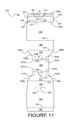
Figure 11 is a plan view of a blank for forming a second embodiment of a carton according to the invention; -
Figure 12 is a perspective view of a package comprising a fully erected carton formed from the blank ofFigure 11 with articles contained therein and an insert received in the pocket thereof; -
Figure 13 is a perspective view of the package ofFigure 12 with the zipper elements removed to expose the insert; -
Figure 14 is a plan view of a blank for forming a third embodiment of a carton according to the invention; -
Figure 15 is a plan view of a blank for forming an insert for the third embodiment of a carton according to the invention; -
Figure 16 is a plan view of the insert blank ofFigure 15 in an erected condition; -
Figure 17 is a perspective view of a package comprising a fully erected carton formed from the carton blank ofFigure 14 with articles contained therein and the insert ofFigure 16 received in the pocket thereof; -
Figure 18 is a perspective view of the package ofFigure 17 with the insert partially removed from the pocket; -
Figure 19 is a plan view of a first blank for forming a first part of a fourth embodiment of a carton according to the invention; -
Figure 20 is a plan view of a second blank for forming a second part of the fourth embodiment of a carton according to the invention; -
Figure 21 is a plan view of an insert for the fourth embodiment of a carton according to the invention in an erected condition; -
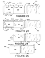
Figure 22 is a plan view of the carton part blanks ofFigures 21 and22 in a first stage of erection; -
Figure 23 is a plan view of the carton part blanks ofFigures 21 and22 in a second stage of erection; -
Figure 24 is a plan view of the carton part blanks ofFigures 21 and22 in a third stage of erection; -
Figure 25 is a plan view of the carton part blanks ofFigures 21 and22 in a fourth stage of erection; -
Figure 26 is a rear perspective view of a package comprising a fully erected carton formed from the carton part blanks ofFigures 21 and22 with articles contained therein and the insert ofFigure 21 received in the pocket thereof; -
Figure 27 is a perspective view of the package ofFigure 26 with the insert partially removed from the pocket; and -
Figure 28 is a front perspective view of the package ofFigure 26 ; -
Figure 29 is a plan view of a blank according of a fifth embodiment of the present invention. - Referring to
Figure 1 , there is shown a carton blank 1 formed from paperboard and having a sidewall securing panel 2, a firstupper side panel 3, a firstlower side panel 4, abase panel 5, a secondlower side panel 6, a secondupper side panel 7, an outertop panel 8, and an innertop panel 9 hinged together in series. - The side
wall securing panel 2 is rectangular in shape and is hinged to a longitudinal edge of the firstupper side panel 3 along one of its longitudinal edges byfold line 21. - The first
upper side panel 3 is rectangular in shape and is hinged to the firstlower side panel 4 along the other longitudinal edge thereof,opposite fold line 21, by afold line 31. - The first
lower side panel 4 is hinged to thebase panel 5 by a pair offold lines base panel 5 is hinged to the secondlower side panel 6 along a pair offold lines - The
base panel 5 is substantially rectangular in shape and includes atab tab fold lines - Each of the
lower side panels legs respective aperture aperture adjacent tab base panel 5. - The
outer edges lower side panel 4 flare outwardly towards the firstupper side panel 3 to foldline 31. Theouter edges lower side panel 6 flare outwardly towards a longitudinal edge of the secondupper side panel 7 to which the secondlower side panel 6 is hinged alongfold line 61. The secondupper side panel 7 is rectangular in shape and in hinged to the outertop panel 8 along the other longitudinal edge thereof,opposite fold line 61, by a fold line - The outer
top panel 8 is rectangular with rounded corners and includes afirst locking panel 82 and anaperture 84 which is circular in this embodiment. The outertop panel 8 is hinged to thefirst locking panel 82 by afold line 85 which is orthogonal to foldline 71. Foldline 85 passes through the centre of theaperture 84, half of which is located within the outertop panel 8 and the other half of which is located in thefirst locking panel 82. The outertop panel 8 is hinged, along a longitudinal edge thereofopposite fold line 71, to a longitudinal edge of the innertop panel 9 byfold line 81. - The inner
top panel 8 is rectangular and includes ansecond locking panel 92, anaperture 94, astop panel 96 and a topwall securing panel 98. The innertop panel 9 is hinged to thesecond locking panel 92 by afold line 95 which is orthogonal to foldline 81. Foldline 95 passes through the centre of theaperture 84, which is circular in this embodiment. Half of theaperture 94 is located within the innertop panel 9 and the other half is located in thesecond locking panel 92. - The
stop panel 96 is trapezoidal in shape and is hinged along the longest of its longitudinal edges to the innertop panel 9 by afold line 93. The topwall securing panel 98 is rectangular in shape and is hinged along one of its longitudinal edges to the inner top panel by afold line 91. - Referring now to
Figure 2 , there is shown an insert blank 10 formed from paperboard and having aninsert panel 11 and aninsert locking panel 12. Theinsert panel 11 is rectangular in shape with aslit 16, which is primarily straight with curved ends. Theinsert panel 11 is hinged along one of its lateral edges to theinsert locking panel 12 by afold line 13. Theinsert locking panel 12 is trapezoidal in shape with curvedlateral edges locking tab 15 extending from its free edge. - The longest of the longitudinal edges of the
insert locking panel 12 is provided by thefold line 13. - As shown in
Figure 3 , theinsert locking panel 12 is folded F1 aboutfold line 13 and thelocking tab 15 is inserted into theslit 16, thereby to retain theinsert locking panel 12 in an overlying relationship with theinsert panel 11, thus providing an erectedinsert 10. - Glue G is then applied to upper portions of the
first locking panel 82 and thesecond locking panel 92 as shown inFigure 4 . Thesecond locking panel 92 is then folded aboutfold line 95, thefirst locking panel 82 is folded F3 aboutfold line 85 and thestop panel 96 is folded aboutfold line 93 as shown inFigure 5 . Thesecond locking panel 92 and first lockingpanel 82 are therefore secured to the innertop panel 9 in a facing relationship. - Glue G is then applied to the top
wall securing panel 98 and thestop panel 96. As shown more clearly inFigure 6 , the innertop panel 9 is then folded F5 aboutfold line 81 such that the topwall securing panel 98 is secured to the secondupper side panel 7 and thestop panel 96 is secured to the outertop panel 8 in facing relationships. It will be appreciated that a pocket is defined between the outertop panel 8 and the innertop panel 9 with the first andsecond locking panels top panel 96 defines a base of the pocket. - It will also be appreciated that fold lines 91 and 71 overlie one another and are arranged to allow the
top panels upper side panel 7. - The
insert 10 is then orientated with theinsert locking panel 12 lowermost as shown inFigure 7 and is inserted I between the outer and innertop panels 8, 9 (i.e. in the pocket). One or both major surfaces of the insert may be coated surfaces. - It will be appreciated that the orientation of the
insert 11 shown inFigures 7 and 8 will result in theinsert locking panel 12 cooperating with thesecond locking panel 92 of the innertop panel 9. However, it will also be appreciated that the orientation of theinsert 11 may be opposite that which is shown such that theinsert locking panel 12 cooperates with thefirst locking panel 82 of the outertop panel 8. Furthermore it will be appreciated that the locking panel additionally provides a spacer for spacing apart the innertop panel 9 and the outertop panel 8 facilitating sliding of the insert within the pocket since frictional contact with the innertop panel 9 and outertop panel 8 is reduced, likewise stoppanel 96 also acts as a spacer element. - Referring now to
Figure 9 , two layers of articles A are placed on thebase panel 5 and the firstlower side panel 4, firstupper side panel 3 and sidewall securing panel 2 are folded aboutfold lines fold line 31 abuts an adjacent edge of the flanges of the lower layer of articles A. The firstupper side panel 3 and sidewall securing panel 2 are then folded further aboutfold line 31 untilfold line 21 abuts an adjacent edge of the flanges of the upper layer of articles A and the sidewall securing panel 2 is then folded aboutfold line 21 to overlie the flanges of the upper layer of articles A. Glue (not shown) is then applied to the exposed surface of the sidewall securing panel 2. - The second
lower side panel 6, secondupper side panel 7 and overlyingtop panels insert 10 therebetween, are then folded aboutfold lines fold line 61 abuts an adjacent edge of the flanges of the lower layer of articles A. The secondupper side panel 7 and overlyingtop panels fold line 61 untilfold line 91 abuts an adjacent edge of the flanges of the upper layer of articles A. The overlyingtop panels overlying fold lines top panel 9 abuts the glue (not shown) on the exposed surface of the sidewall securing panel 2, thus securing the carton around the articles A. - As shown in
Figure 10 , theinsert 10 is slideably movable within the pocket defined between the outertop panel 8 and the innertop panel 9. An exposed edge of theinsert panel 11 is accessible by virtue of theapertures insert 10 is prevented by virtue of the cooperating lockingpanels 12 and 92 (in this embodiment) or 82 (as discussed above). - Thus, a tubular structure is provided around the articles A by the
carton 1 which incorporates a pocket within thetop wall structure - The invention therefore provides a means for increasing the coated area of a carton by virtue of the
insert 10 without increasing the overall package size and/or for accommodating additional promotional material such as brochures, CDs and the like by virtue of the pocket. - Referring now to
Figure 11 , there is shown acarton blank 100 for forming a second carton embodiment. The blank 100 is formed from paperboard and includes a securingpanel 120, an outertop panel 130, a firstupper side panel 140, a firstlower side panel 150, abase panel 160, a secondlower side panel 170, a secondupper side panel 180, an innertop panel 190 and a topwall securing panel 192. - The securing
panel 120 is substantially rectangular in shape and includes twozipper elements securing panel portion 120a and a lowersecuring panel portion 120b. Thezipper elements perforated lines 124, each of which includes a frangiblecentral portion central portions transverse cut line 125. The frangible line which partially defines the uppersecuring panel portion 120a is shaped to form a securingtongue 128. - The securing
panel 120 is hinged at one of its longitudinal edges byfold line 121 to the outertop panel 130. The outertop panel 130 is rectangular in shape with rounded corners. The outertop panel 130 is hinged along the other if its longitudinal edges byfold line 131 to one of the longitudinal edges of the firstupper side panel 140. The firstupper side panel 140 is rectangular in shape and is hinged along its other longitudinal edge byfold line 141 to the firstlower side panel 150. - The first
lower side panel 150 is hinged to thebase panel 160 by a pair offold lines base panel 160 is hinged to the secondlower side panel 170 along a pair offold lines - The
base panel 160 is substantially rectangular in shape and includes atab tab fold lines - Each of the
lower side panels legs respective aperture aperture adjacent tab base panel 160. - The
outer edges lower side panel 150 flare outwardly towards the firstupper side panel 140 to foldline 141. Theouter edges lower side panel 170 flare outwardly towards a longitudinal edge of the secondupper side panel 180 to which the secondlower side panel 170 is hinged alongfold line 171. The secondupper side panel 180 is rectangular in shape and includes alocking slit 182 struck therein. The secondupper side panel 180 is hinged to the innertop panel 190 along the other longitudinal edge thereof,opposite fold line 171, by afold line 181. - The inner
top panel 190 is rectangular in shape with rounded corners. The innertop panel 190 is hinged along the other if its longitudinal edges byfold line 191 to one of the longitudinal edges of the topwall securing panel 192, which is rectangular in shape. - In order to erect the carton to the condition shown in
Figure 12 , Glue G is applied to the lowersecuring panel portion 120b. Two layers of articles A are then placed on thebase panel 160 and the secondlower side panel 170, the secondupper side panel 180, the innertop panel 190 and the topwall securing panel 192 are folded aboutfold lines 161a and 162b untilfold line 171 abuts an edge of the flanges of the lower layer of articles A. The secondupper side panel 180, the innertop panel 190 and the topwall securing panel 192 are then folded aboutfold line 171 untilfold line 181 abuts an edge of the flanges of the upper layer of the articles A. The innertop panel 190 and the topwall securing panel 192 are then folded aboutfold line 181 until the innertop panel 190 overlies the flanges of the upper layer of the articles A and the topwall securing panel 192 is folded aboutfold line 191 such that it depends therefrom. - Glue (not shown) is then applied to the exposed surface of the top
wall securing panel 192. The firstlower side panel 150, the firstupper side panel 140, the outertop panel 130 and the securingpanel 120 are then folded aboutfold lines fold line 141 abuts an edge of the flanges of the lower layer of articles A. The firstupper side panel 140, the outertop panel 130 and the securing panel are then folded aboutfold line 141 untilfold line 131 abuts an edge of the flanges of the upper layer of articles A and the firstupper side panel 140 overlies the topwall securing panel 192, thus securing the twopanels - Promotional material P is then placed on the inner
top panel 190. The outertop panel 130 and the securing panel are then folded aboutfold line 131 until the outertop panel 130 overlies the promotional material P and the innertop panel 190. The securingpanel 120 is then folded aboutfold line 121 until it overlies the secondupper side panel 180, thus securing the twopanels securing panel portion 120b. - Thus, a tubular structure is provided around the articles A by the
carton 100 which incorporates a pocket within thetop wall structure - In order to remove the promotional material, a user urges a finger (not shown) against the
transverse cut line 125 to gain access to the underside of thezipper elements zipper elements top panel 130 and securingpanel 120 are folded F100 about thefold line 131 to expose the promotional material P. A secondary lock is provided by the securingtongue 128 which cooperates with the locking slit 182. - Referring now to
Figure 14 , there is shown is shown acarton blank 200 for forming a third carton embodiment. The blank 200 formed from paperboard and includes abase securing panel 220, abase panel 230, afirst side panel 240, atop panel 250, anouter side panel 260, aninner side panel 270 and a sidewall securing panel 280. - The
base securing panel 220 is trapezoidal in shape and is hinged along the longest of its longitudinal edges byfold line 221 to thebase panel 230. Thebase panel 230 is rectangular in shape and is hinged at the other of its longitudinal edges byfold line 231 to thefirst side panel 240. Thefist side panel 240 is rectangular in shape with one of its lateral edges being provided by thefold line 231. Thefirst side panel 240 is hinged at its other lateral edge byfold line 241 to thetop panel 250. Thetop panel 250 is rectangular in shape and one of its longitudinal edges is provided byfold line 241. Thetop panel 250 is hinged along its other longitudinal edge byfold line 251 to theouter side panel 260. - The
outer side panel 260 is rectangular in shape and one of its lateral edges is provided byfold line 251. Theouter side panel 260 includes afirst locking panel 262 and anaperture 264, which is circular in this embodiment. Theouter side panel 260 is hinged to thefirst locking panel 262 by afold line 265 which is orthogonal to foldline 251. Foldline 265 passes through the centre of theaperture 264, half of which is located within theouter side panel 260 and the other half of which is located in thefirst locking panel 262. Theouter side panel 260 is hinged, along its other lateral edge, to a lateral edge of theinner side panel 270 byfold line 261. - The
inner side panel 270 is rectangular and includes asecond locking panel 272, anaperture 274 and astop panel 276. Theinner side panel 270 is hinged to thesecond locking panel 272 by afold line 275 which is orthogonal to foldline 261. Foldline 275 passes through the centre of theaperture 274, which is circular in this embodiment. Half of theaperture 274 is located within theinner side panel 270 and the other half is located in thesecond locking panel 272. - The
stop panel 276 is trapezoidal in shape and is hinged along the longest of its longitudinal edges to theinner side panel 270 by a fold line 273. Theinner side panel 270 is hinged along its other lateral edge byfold line 271 to the sidewall securing panel 280, which foldline 271 provides a longitudinal edge of therectangular securing panel 280. - Referring now to
Figure 15 , there is shown an insert blank 210 formed from paperboard and having aninsert panel 211 and aninsert locking panel 212. Theinsert panel 211 is rectangular in shape with aslit 216, which is primarily straight with curved ends. Theinsert panel 211 is hinged along one of its longitudinal edges to theinsert locking panel 212 by afold line 213. Theinsert locking panel 212 is trapezoidal in shape with curvedlateral edges locking tab 215 extending from its free edge. The longest of the longitudinal edges of theinsert locking panel 212 is provided by thefold line 213. - As shown in
Figure 16 , theinsert locking panel 212 is folded aboutfold line 213 and thelocking tab 215 is inserted into theslit 216, thereby to retain theinsert locking panel 212 in an overlying relationship with theinsert panel 211, thus providing an erectedinsert 210. - Erecting the carton from the blank 200 is carried out in a similar fashion to the first embodiment. Glue (not shown) is applied to the first and
second locking panels respective fold lines side wall panel stop panel 276 is folded about its fold line 273 to lie adjacent theinner side panel 270 on the same side thereof as thesecond locking panel 272. Glue (not shown) is also applied to the sidewall securing panel 280 and thesecond locking panel 272 and theinner side panel 270 is folded aboutfold line 261 until it overlies theouter side panel 260 such that theside wall panel 280 is secured to thetop panel 250 and thestop panel 276 is secured to theouter side panel 260. - The
insert 210 is inserted with theinsert locking panel 212 end first into the pocket defined between the outer andinner side panels base panel 230 and the carton is wrapped around them as shown inFigure 17 . Glue (not shown) is applied to the exposed major surface of thebase securing panel 220 and theinner side panel 270 is brought into contact with the glue, thus securing thepanels - As shown in
Figure 18 , theinsert 210 is slideably movable within the pocket defined between theouter side panel 260 and theinner side panel 270. An exposed edge of theinsert panel 211 is accessible by virtue of theapertures insert 210 is prevented by virtue of the cooperating lockingpanels - Thus, a tubular structure is provided around the articles A by the
carton 200 which incorporates a pocket within theside wall structure -
Figure 19 shows a first blank 301 for forming a first part of a fourth carton embodiment. The first blank 301 is formed from paperboard with one major surface thereof comprising a coated surface (surface shown inFigure 19 ). The first blank 301 includes a securingpanel 320, anouter side panel 330, aninner side panel 340 and a first sidewall securing panel 350. - The securing
panel 320 is rectangular and includes azipper element 322 struck therefrom to define a firstsecuring panel portion 320a and a secondsecuring panel portion 320b. Thezipper element 322 includes agripping tab 324 which extends from one of the lateral edges of the securingpanel 320. The securing panel is hinged along one of its longitudinal edges byfold line 321 to theouter side panel 330. - The
outer side panel 330 is rectangular in shape and one of its lateral edges is provided byfold line 321. Theouter side panel 330 includes afirst locking panel 332 and anaperture 334, which is circular in this embodiment. Theouter side panel 330 is hinged to thefirst locking panel 332 by afold line 335 which is orthogonal to foldline 321. Foldline 335 passes through the centre of theaperture 334, half of which is located within theouter side panel 330 and the other half of which is located in thefirst locking panel 332. Theouter side panel 330 is hinged, along its other lateral edge, to a lateral edge of theinner side panel 340 byfold line 331. - The
inner side panel 340 is rectangular and includes asecond locking panel 342, anaperture 344 and astop panel 346. Theinner side panel 340 is hinged to thesecond locking panel 342 by afold line 345 which is orthogonal to foldline 331. Foldline 345 passes through the centre of theaperture 344, which is circular in this embodiment. Half of theaperture 344 is located within theinner side panel 340 and the other half is located in thesecond locking panel 342. - The
stop panel 346 is trapezoidal in shape and is hinged along the longest of its longitudinal edges to theinner side panel 340 by afold line 343. Theinner side panel 340 is hinged along its other lateral edge byfold line 341 to the first sidewall securing panel 350, which foldline 341 provides a longitudinal edge of the rectangular first sidewall securing panel 350. -
Figure 20 shows a second blank 302 for forming a second part of the fourth carton embodiment. The second blank 302 is formed from foldable plastics sheet material and includes abase securing panel 360, abase panel 370, afirst side panel 380 and a second sidewall securing panel 390. - The
base securing panel 360 is trapezoidal in shape and is hinged along the longest of its longitudinal edges byfold line 361 to thebase panel 370. Thebase panel 370 is rectangular in shape and is hinged at the other of its longitudinal edges byfold line 371 to thefirst side panel 380. Thefist side panel 380 is rectangular in shape with one of its lateral edges being provided by thefold line 371. Thefirst side panel 380 is hinged at its other lateral edge byfold line 381 to the second sidewall securing panel 390. The second sidewall securing panel 390 is rectangular in shape and one of its longitudinal edges is provided byfold line 381. -
Figure 21 shows an insert blank 310 formed from paperboard and having aninsert panel 311 and aninsert locking panel 312. Theinsert panel 311 is rectangular in shape with aslit 316, which is primarily straight with curved ends. Theinsert panel 311 is hinged along one of its longitudinal edges to theinsert locking panel 312 by afold line 313. Theinsert locking panel 312 is trapezoidal in shape with curved lateral edges and includes alocking tab 315 extending from its free edge. The longest of the longitudinal edges of theinsert locking panel 312 is provided by thefold line 313. - The
insert locking panel 312 is folded aboutfold line 313 and thelocking tab 315 is inserted into theslit 316, thereby to retain theinsert locking panel 312 in an overlying relationship with theinsert panel 311, thus providing an erectedinsert 310. - Reference is now made to
Figures 22 to 25 , which show various stages of erection and assembly of the twocarton blanks second locking panels first locking panel 332 is folded F301 aboutfold line 335 to secure it to theouter side panel 330. Thesecond locking panel 342 is folded F300 aboutfold line 345 and is secured to theinner side panel 340. - The
stop panel 346 is folded aboutfold line 343 and glue G is applied to the exposed surface thereof. Glue is also applied to the first sidewall securing panel 350. - The
inner side panel 340 is then folded aboutfold line 331 until theinner side panel 340 overlies theouter side panel 330, thus securing the sidewall securing panel 350 to the secondsecuring panel portion 320b and thestop panel 346 to theouter side panel 330. - Glue G is then applied to the first
securing panel portion 320a, which is then brought into contact with the second sidewall securing panel 390, thus securing thepanels Figure 25 and providing an assembled blank 300. - Erecting the carton from the assembled blank 300 is carried out in a similar fashion to third embodiment. The
insert 310 is inserted with theinsert locking panel 312 end first into the pocket defined between the outer andinner side panels - Four levels of articles A are then placed on the
base panel 370 and the carton is wrapped around them as shown inFigures 26 to 28 . Glue (not shown) is applied to the exposed major surface of thebase securing panel 360 and theinner side panel 340 is brought into contact with the glue, thus securing thepanels - As shown in
Figure 27 , theinsert 310 is slideably movable within the pocket defined between theouter side panel 330 and theinner side panel 340. An exposed edge of theinsert panel 311 is accessible by virtue of theapertures insert 310 is prevented by virtue of the cooperating lockingpanels - Thus, a tubular structure is provided around the articles A by the
carton 300 which incorporates a pocket within theside wall structure - It will be appreciated by those skilled in the art that, by virtue of the construction of the
carton 300, the facing surface of theinner side panel 340 is a coated surface. It will also be appreciated that thefront panel 380 is transparent, thus rendering both the articles A and the coated surface of theside panel 340 visible therethrough. - Accordingly, this arrangement provides additional coated surface than would otherwise be available by the use of a transparent front panel. This arrangement also provides, as with all of the previously disclosed embodiments, a means for increasing the coated area of a carton by virtue of the
insert 310 without increasing the overall package size and/or for accommodating additional promotional material such as brochures, CDs and the like by virtue of the pocket. -
Figure 29 illustrates a fifth embodiment of the present invention which is similar to the second embodiment shown inFigures 11 to 13 ; like reference signs have been used to indicate like features where possible, with prefix "4" replacing prefix "1" and therefore only the differences from the embodiment illustrated inFigures 11 to 13 will be described in any greater detail. - In the embodiment shown in
Figure 29 it will be appreciated that the outertop panel 430 is hingedly connected to the innertop panel 490 alongfold line 491. The topwall securing panel 492 is hingedly connected to the firstupper side panel 440 alongfold line 431. In order to construct a carton from the blank 400 the outer top panel is folded F401 aboutfold line 491 to overlie the innertop panel 490, an insert may be placed between the innertop panel 490 and the outertop panel 430 before folding the outertop panel 430 to overlie the innertop panel 490 or alternatively may be inserted afterwards. The blank 400 is constructed into a tubular structure by folding about one or more articles (not shown) and the innertop panel 490 is secured to the topwall securing panel 492 by adhesive, mechanical or other suitable securing means. - It will be appreciated that in yet further embodiments of the present invention the blank of
Figure 11 or29 may be provided with one or more locking panels (82, 92) such as those illustrated inFigure 1 ; optionally a stop panel 96 (shown inFigure 1 )may also be provided. Furthermore it will be appreciated that the locking panel and/or the stop panel shown in the embodiments ofFigure1 ,14 and19 may be removed. Optionally these embodiments may be provided with the tear feature or zipper element described in relation to the second and fifth embodiments and as illustrated inFigures 11 and29 . - It will be appreciated that the locking panels and/or the stop panel in addition to providing a locking/stopping function for retain the insert sandwiched in between the inner top panel and outer top panel also provide a spacer means between the inner top panel and the outer top panel which facilitates the withdrawal/insertion of an insert between the panels forming the pocket.
- It will be recognised that as used herein, directional references such as "top", "base", "end", "side", "inner", "outer", "upper" and "lower" do not limit the respective panels to such orientation, but merely serve to distinguish these panels from one another. Any reference to hinged connection should not be construed as necessarily referring to a single fold line only: indeed it is envisaged that hinged connection can be formed from one or more of one of the following, a score line, a frangible line or a fold line, without departing from the scope of invention.
- It will be appreciated by those skilled in the art that several variations to the above construction are envisaged without departing from the scope of the invention. For example, whilst the pocket is incorporated in the top wall or side wall of the carton embodiments disclosed here, it may be incorporated within the base panel or any other panel. It is also envisaged to provide a carton according to the invention which comprises two or more pockets incorporated in any of the walls thereof. It is further envisaged that a single wall may comprise two or more pockets, for example which overlie one another.
- Furthermore, whilst the
stop panels outer panel inner panel stop panels outer panels inner panel outer panel - Alternatively, it is also envisaged that the
stop panels outer panel inner panel stop panels insert stop panel insert - The
apertures - Whilst methods of erection of the cartons disclosed herein have been included, they are described for illustration purposes only and should not be considered as limiting the erection of the cartons to such methods. It will be appreciated that several different methods are envisaged which include the same steps in a different order and/or additional or less steps than those which are described herein.
- Moreover, whilst the embodiments described herein comprise paperboard and foldable plastic sheet material, any other suitable material which is capable of performing a similar function may be used.
Claims (15)
- A carton or wrap around carrier for receiving articles, the carton or wrap around carrier comprising first and second side walls, a top wall and a bottom wall hingedly connected together to form a tubular structure and an insert associated with the tubular structure, at least one of the walls comprising a pair of inner and outer panels in overlying relationship to form a pocket therebetween, the insert being received in the pocket for sliding movement with respect to the tubular structure.
- A carton or wrap around carrier according to claim 1 wherein the inner panel is hinged to the outer panel by hinge line.
- A carton or wrap around carrier according to claim 1 or 2, wherein the at least one wall comprises an abutment for limiting sliding movement of the insert.
- A carton or wrap around carrier according to claim 3, wherein the abutment comprises a pocket locking panel hingedly connected to the at least one wall and located in the pocket.
- A carton or wrap around carrier according to any of claims 1 to 4 wherein there comprises a stop panel hinged to one of the inner or outer panels and being secured to the other of the inner or outer panel such that an end stop is formed to close the pocket.
- A carton or wrap around carrier according to any of claims 1 to 4 wherein a spacer is provided to space apart the inner panel and the outer panel preferably the spacer is provided by the locking panel and/or the stop panel.
- A carton or wrap around carrier according to any of claims 1 to 4, wherein the insert is slidingly movable between a retracted position where the insert is fully received in the pocket and an extended position where the insert is disposed outside the pocket except for an inner end portion of the insert.
- A carton or wrap around carrier according to claim 5, wherein the insert includes an insert locking panel for cooperation with the abutment of the at least one wall to limit relative movement of the insert.
- A carton or wrap around carrier according to claim 8, wherein the insert further includes a main panel, the locking panel being hingedly connected to the main panel and folded into a face-contacting relationship with the main panel to cooperate with the abutment.
- A carton or wrap around carrier according to any of claims 1 to 9, wherein the inner and outer panels are secured together by releasable securing means preferably the releasable securing means is arranged to provide access to the insert without providing access to articles contained in the carton.
- A carton or wrap around carrier according to claim 10, wherein the releasable securing means comprises a tongue connected to one of the inner and outer panels which cooperates with a slit fixed relative to the other of the inner and outer panels.
- A carton or wrap around carrier according to claim 11 wherein the releasable securing means comprises a zipper element, the zipper element is removable to expose the tongue.
- A carton or wrap around carrier according to any of claims 1 to 12, wherein one of the walls is transparent or translucent and preferably one of the remaining walls is opaque and comprises a coated surface which is visible through the transparent or translucent wall.
- A carton or wrap around carrier according to claim 13, wherein the opaque wall comprises two overlying panels preferably the two overlying panels are the inner and outer panels which form the pocket.
- A blank for forming a carton or wrap around carrier according to any preceding claim.
Applications Claiming Priority (1)
| Application Number | Priority Date | Filing Date | Title |
|---|---|---|---|
| GB0715901A GB0715901D0 (en) | 2007-08-15 | 2007-08-15 | Cartons |
Publications (2)
| Publication Number | Publication Date |
|---|---|
| EP2025608A2 true EP2025608A2 (en) | 2009-02-18 |
| EP2025608A3 EP2025608A3 (en) | 2009-04-15 |
Family
ID=38566421
Family Applications (1)
| Application Number | Title | Priority Date | Filing Date |
|---|---|---|---|
| EP08162444A Withdrawn EP2025608A3 (en) | 2007-08-15 | 2008-08-14 | Carton and blank therefor |
Country Status (3)
| Country | Link |
|---|---|
| EP (1) | EP2025608A3 (en) |
| GB (1) | GB0715901D0 (en) |
| RU (1) | RU2008133653A (en) |
Cited By (1)
| Publication number | Priority date | Publication date | Assignee | Title |
|---|---|---|---|---|
| US20210061531A1 (en) * | 2019-08-27 | 2021-03-04 | Graphic Packaging International, Llc | Carton With Tamper-Evident Feature |
Family Cites Families (6)
| Publication number | Priority date | Publication date | Assignee | Title |
|---|---|---|---|---|
| JPH11255233A (en) * | 1998-03-06 | 1999-09-21 | Asahi Printing And Packaging Co Ltd | Packaging box with indication slip attached |
| FR2798648B1 (en) * | 1999-09-17 | 2001-12-07 | Lipha | CARTON BOX-TYPE PACKAGING ARTICLE AND ITS USE FOR THE PACKAGING OF MEDICINES |
| JP2002059918A (en) * | 2000-08-21 | 2002-02-26 | Taiho Ind Co Ltd | Product storage box |
| JP2003341719A (en) * | 2002-05-28 | 2003-12-03 | Toppan Printing Co Ltd | Promotional display board for multipack |
| ITFI20040137A1 (en) * | 2004-06-15 | 2004-09-15 | Project Sas | CARTON BOX OR SIMILAR CONTAINER WITH ASSOCIATED SLIDER |
| JP2006036334A (en) * | 2004-07-29 | 2006-02-09 | Kyocera Mita Corp | Paper-made packing case |
-
2007
- 2007-08-15 GB GB0715901A patent/GB0715901D0/en not_active Ceased
-
2008
- 2008-08-14 EP EP08162444A patent/EP2025608A3/en not_active Withdrawn
- 2008-08-15 RU RU2008133653/12A patent/RU2008133653A/en not_active Application Discontinuation
Cited By (2)
| Publication number | Priority date | Publication date | Assignee | Title |
|---|---|---|---|---|
| US20210061531A1 (en) * | 2019-08-27 | 2021-03-04 | Graphic Packaging International, Llc | Carton With Tamper-Evident Feature |
| US12084242B2 (en) * | 2019-08-27 | 2024-09-10 | Graphic Packaging International, Llc | Carton with tamper-evident feature |
Also Published As
| Publication number | Publication date |
|---|---|
| GB0715901D0 (en) | 2007-09-26 |
| RU2008133653A (en) | 2010-02-20 |
| EP2025608A3 (en) | 2009-04-15 |
Similar Documents
| Publication | Publication Date | Title |
|---|---|---|
| US6079563A (en) | Container for compressors and other goods | |
| US5460265A (en) | Blank construction and package for a compact disc | |
| JP4733150B2 (en) | Carton with intermeshing divider | |
| JP4563459B2 (en) | Wrap-around carton with dispensing features | |
| US9764874B2 (en) | Slide opening display and mail package | |
| CN103582600A (en) | Carton for packaging articles, blank and method for forming same | |
| EP3147230A1 (en) | Child resistant packaging | |
| CN104507822A (en) | Carton and carton blank for forming a carton | |
| CA2805061C (en) | Display ready container | |
| CA2212233A1 (en) | Lined carton of triangular cross section | |
| WO2001045091A2 (en) | Compact disc display and mailing packages | |
| US20120279961A1 (en) | Dispensing container | |
| CA2386594C (en) | Carton and carton blank | |
| JP2005096857A (en) | Illegal opening prevention case | |
| GB2319241A (en) | A dispensing tray | |
| AU2007225204A1 (en) | Package for holding multiple media discs and methods of making the same | |
| US20090314669A1 (en) | Package for discs | |
| JP5953765B2 (en) | Cardboard box with display board | |
| JP3130541U (en) | Packing material | |
| EP2125540B1 (en) | Packet for containing a tobacco product | |
| EP1687210B1 (en) | Carton and carton blank | |
| EP1892190A2 (en) | A carton and blank | |
| EP1810928B1 (en) | Container | |
| JP2024085306A (en) | Packing box | |
| EP2019044A1 (en) | Container for paper napkins and package of paper napkins comprising said container |
Legal Events
| Date | Code | Title | Description |
|---|---|---|---|
| PUAI | Public reference made under article 153(3) epc to a published international application that has entered the european phase |
Free format text: ORIGINAL CODE: 0009012 |
|
| AK | Designated contracting states |
Kind code of ref document: A2 Designated state(s): AT BE BG CH CY CZ DE DK EE ES FI FR GB GR HR HU IE IS IT LI LT LU LV MC MT NL NO PL PT RO SE SI SK TR |
|
| AX | Request for extension of the european patent |
Extension state: AL BA MK RS |
|
| PUAL | Search report despatched |
Free format text: ORIGINAL CODE: 0009013 |
|
| AK | Designated contracting states |
Kind code of ref document: A3 Designated state(s): AT BE BG CH CY CZ DE DK EE ES FI FR GB GR HR HU IE IS IT LI LT LU LV MC MT NL NO PL PT RO SE SI SK TR |
|
| AX | Request for extension of the european patent |
Extension state: AL BA MK RS |
|
| 17P | Request for examination filed |
Effective date: 20090811 |
|
| 17Q | First examination report despatched |
Effective date: 20090911 |
|
| AKX | Designation fees paid |
Designated state(s): AT BE BG CH CY CZ DE DK EE ES FI FR GB GR HR HU IE IS IT LI LT LU LV MC MT NL NO PL PT RO SE SI SK TR |
|
| STAA | Information on the status of an ep patent application or granted ep patent |
Free format text: STATUS: THE APPLICATION IS DEEMED TO BE WITHDRAWN |
|
| 18D | Application deemed to be withdrawn |
Effective date: 20100122 |