EP2025596A1 - A hermetically sealable container and the method for manufacturing the container - Google Patents
A hermetically sealable container and the method for manufacturing the container Download PDFInfo
- Publication number
- EP2025596A1 EP2025596A1 EP08161080A EP08161080A EP2025596A1 EP 2025596 A1 EP2025596 A1 EP 2025596A1 EP 08161080 A EP08161080 A EP 08161080A EP 08161080 A EP08161080 A EP 08161080A EP 2025596 A1 EP2025596 A1 EP 2025596A1
- Authority
- EP
- European Patent Office
- Prior art keywords
- container
- tuck
- tub
- sealing
- barrier
- Prior art date
- Legal status (The legal status is an assumption and is not a legal conclusion. Google has not performed a legal analysis and makes no representation as to the accuracy of the status listed.)
- Granted
Links
- 238000000034 method Methods 0.000 title claims description 11
- 238000004519 manufacturing process Methods 0.000 title claims description 4
- 239000000463 material Substances 0.000 claims abstract description 55
- 238000007789 sealing Methods 0.000 claims abstract description 25
- 230000004888 barrier function Effects 0.000 claims abstract description 20
- 229920002678 cellulose Polymers 0.000 claims abstract description 12
- 239000001913 cellulose Substances 0.000 claims abstract description 12
- 235000013305 food Nutrition 0.000 claims abstract description 5
- 239000010410 layer Substances 0.000 claims description 26
- 239000007888 film coating Substances 0.000 claims description 6
- 238000009501 film coating Methods 0.000 claims description 6
- 238000004026 adhesive bonding Methods 0.000 claims description 5
- 238000010438 heat treatment Methods 0.000 claims description 5
- 238000005452 bending Methods 0.000 claims description 4
- -1 polyethylene Polymers 0.000 claims description 4
- 238000005192 partition Methods 0.000 claims description 3
- 230000002093 peripheral effect Effects 0.000 claims description 3
- 239000002028 Biomass Substances 0.000 claims description 2
- 239000004698 Polyethylene Substances 0.000 claims description 2
- 239000004743 Polypropylene Substances 0.000 claims description 2
- 229920000573 polyethylene Polymers 0.000 claims description 2
- 229920001155 polypropylene Polymers 0.000 claims description 2
- 238000007493 shaping process Methods 0.000 claims description 2
- 239000002356 single layer Substances 0.000 claims description 2
- 210000002105 tongue Anatomy 0.000 description 8
- 238000004321 preservation Methods 0.000 description 4
- 239000002699 waste material Substances 0.000 description 3
- 238000000576 coating method Methods 0.000 description 2
- 238000004891 communication Methods 0.000 description 2
- 230000035515 penetration Effects 0.000 description 2
- 239000000853 adhesive Substances 0.000 description 1
- 230000001070 adhesive effect Effects 0.000 description 1
- 229920000704 biodegradable plastic Polymers 0.000 description 1
- 239000011248 coating agent Substances 0.000 description 1
- 239000000356 contaminant Substances 0.000 description 1
- 238000001816 cooling Methods 0.000 description 1
- 230000001419 dependent effect Effects 0.000 description 1
- 238000005516 engineering process Methods 0.000 description 1
- 230000007613 environmental effect Effects 0.000 description 1
- 239000007789 gas Substances 0.000 description 1
- 239000011261 inert gas Substances 0.000 description 1
- 230000003993 interaction Effects 0.000 description 1
- 239000007800 oxidant agent Substances 0.000 description 1
- 238000004806 packaging method and process Methods 0.000 description 1
- 235000019629 palatability Nutrition 0.000 description 1
- 238000004078 waterproofing Methods 0.000 description 1
Images
Classifications
-
- B—PERFORMING OPERATIONS; TRANSPORTING
- B65—CONVEYING; PACKING; STORING; HANDLING THIN OR FILAMENTARY MATERIAL
- B65B—MACHINES, APPARATUS OR DEVICES FOR, OR METHODS OF, PACKAGING ARTICLES OR MATERIALS; UNPACKING
- B65B43/00—Forming, feeding, opening or setting-up containers or receptacles in association with packaging
- B65B43/08—Forming three-dimensional containers from sheet material
-
- B—PERFORMING OPERATIONS; TRANSPORTING
- B65—CONVEYING; PACKING; STORING; HANDLING THIN OR FILAMENTARY MATERIAL
- B65B—MACHINES, APPARATUS OR DEVICES FOR, OR METHODS OF, PACKAGING ARTICLES OR MATERIALS; UNPACKING
- B65B7/00—Closing containers or receptacles after filling
- B65B7/16—Closing semi-rigid or rigid containers or receptacles not deformed by, or not taking-up shape of, contents, e.g. boxes or cartons
- B65B7/28—Closing semi-rigid or rigid containers or receptacles not deformed by, or not taking-up shape of, contents, e.g. boxes or cartons by applying separate preformed closures, e.g. lids, covers
- B65B7/2842—Securing closures on containers
- B65B7/2871—Securing closures on containers by gluing
-
- B—PERFORMING OPERATIONS; TRANSPORTING
- B65—CONVEYING; PACKING; STORING; HANDLING THIN OR FILAMENTARY MATERIAL
- B65B—MACHINES, APPARATUS OR DEVICES FOR, OR METHODS OF, PACKAGING ARTICLES OR MATERIALS; UNPACKING
- B65B7/00—Closing containers or receptacles after filling
- B65B7/16—Closing semi-rigid or rigid containers or receptacles not deformed by, or not taking-up shape of, contents, e.g. boxes or cartons
- B65B7/28—Closing semi-rigid or rigid containers or receptacles not deformed by, or not taking-up shape of, contents, e.g. boxes or cartons by applying separate preformed closures, e.g. lids, covers
- B65B7/2842—Securing closures on containers
- B65B7/2878—Securing closures on containers by heat-sealing
-
- B—PERFORMING OPERATIONS; TRANSPORTING
- B65—CONVEYING; PACKING; STORING; HANDLING THIN OR FILAMENTARY MATERIAL
- B65D—CONTAINERS FOR STORAGE OR TRANSPORT OF ARTICLES OR MATERIALS, e.g. BAGS, BARRELS, BOTTLES, BOXES, CANS, CARTONS, CRATES, DRUMS, JARS, TANKS, HOPPERS, FORWARDING CONTAINERS; ACCESSORIES, CLOSURES, OR FITTINGS THEREFOR; PACKAGING ELEMENTS; PACKAGES
- B65D3/00—Rigid or semi-rigid containers having bodies or peripheral walls of curved or partially-curved cross-section made by winding or bending paper without folding along defined lines
- B65D3/28—Other details of walls
- B65D3/30—Local reinforcements, e.g. metallic rims
-
- B—PERFORMING OPERATIONS; TRANSPORTING
- B65—CONVEYING; PACKING; STORING; HANDLING THIN OR FILAMENTARY MATERIAL
- B65D—CONTAINERS FOR STORAGE OR TRANSPORT OF ARTICLES OR MATERIALS, e.g. BAGS, BARRELS, BOTTLES, BOXES, CANS, CARTONS, CRATES, DRUMS, JARS, TANKS, HOPPERS, FORWARDING CONTAINERS; ACCESSORIES, CLOSURES, OR FITTINGS THEREFOR; PACKAGING ELEMENTS; PACKAGES
- B65D77/00—Packages formed by enclosing articles or materials in preformed containers, e.g. boxes, cartons, sacks or bags
- B65D77/10—Container closures formed after filling
- B65D77/20—Container closures formed after filling by applying separate lids or covers, i.e. flexible membrane or foil-like covers
- B65D77/2024—Container closures formed after filling by applying separate lids or covers, i.e. flexible membrane or foil-like covers the cover being welded or adhered to the container
-
- B—PERFORMING OPERATIONS; TRANSPORTING
- B65—CONVEYING; PACKING; STORING; HANDLING THIN OR FILAMENTARY MATERIAL
- B65D—CONTAINERS FOR STORAGE OR TRANSPORT OF ARTICLES OR MATERIALS, e.g. BAGS, BARRELS, BOTTLES, BOXES, CANS, CARTONS, CRATES, DRUMS, JARS, TANKS, HOPPERS, FORWARDING CONTAINERS; ACCESSORIES, CLOSURES, OR FITTINGS THEREFOR; PACKAGING ELEMENTS; PACKAGES
- B65D2577/00—Packages formed by enclosing articles or materials in preformed containers, e.g. boxes, cartons, sacks, bags
- B65D2577/10—Container closures formed after filling
- B65D2577/20—Container closures formed after filling by applying separate lids or covers
- B65D2577/2025—Multi-layered container, e.g. laminated, coated
Definitions
- This invention relates to the preservation of fresh food products and, in particular, concerns a container comprising a tub to hold and display the products and a sealing barrier, which may be sealed to the tub to define a closed and isolated containment cavity hermetically sealed from the surrounding environment.
- the invention also relates to a method for manufacturing the container.
- tub containers for the packaging and preservation of fresh products tub containers are employed in which the walls of the tub are made of a paper material and coated with waterproofing film layers made from material compatible, on the one hand, with the products to be contained and, on the other, with the heat treatments (e.g. for preservation purposes) applied to the above-mentioned products and to the container.
- the thicknesses of the paper material are normally relatively high - even if measurable in millimetres - so as to grant a structural rigidity to the tub adequate for its purpose.
- the film materials consist, on the other hand, of thinner coatings applied to the layer of cellulose material to make it impermeable and non-breathable with respect to the content and the outside environment.
- the sealing barriers are normally made from film, of an identical nature to the films used for coating the paper material, which are stretched over the tub after filling and then heat sealed to the edges of the tub to hermetically seal the inside space, thereby preserving the contents.
- shelf inert gases may also be introduced into the tub cavity with the aim of both protecting the contained product against the possibility of interaction with oxidising agents and/or contaminants in the atmosphere, and balancing the internal pressure of the container with the external atmospheric pressure to make the penetration of air inside the cavity more difficult.
- a much desired objective of the above-mentioned technology is the obtainment of methods to increasingly extend the shelf life of the products.
- containers made from paper material such a result is always difficult to achieve as the manufacturing of the container by deep drawing a flat sheet of paper material forms thin folds - as is particularly evident inside the corners of the container and inside the cavity - with overlapping of the materials thereby forming channels which, even though they are narrow, are practically uninterruptible and may bring the outside environment into communication with the inside cavity of the container.
- the fundamental problem to be solved remains that of providing edge structures able to substantially provide an equally effective answer to the contrasting aspects of the problem concerning, on the one hand, hermetic seal and, on the other, structural rigidity.
- the main aim of this invention is therefore to provide a container whose sealing and structural strength characteristics are substantially equivalent to each other in terms of relative importance.
- Another aim of this invention is to provide a container able to provide a longer shelf life compared with prior art containers.
- a further aim of the present invention is to provide containers which may be manufactured economically, bearing in mind that that they are substantially single-use disposable containers.
- Yet another aim of the present invention is to provide a fully biodegradable and fully compostable container without residue of any kind in the environment when disposed of as waste.
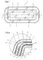
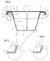
- the container 1 essentially comprises (see figure 2 ) a tub 2 and a sealing barrier 3 which may be reciprocally heat sealed to define a cavity 4 to hold the product closed and isolated from the surrounding environment.
- the tub 2 has a top edge 5 running continuously along its border and comprises a wall 6 surrounding the containment cavity 4, consisting of a first stratiform element 7 made of cellulose material coated on both sides, in a first embodiment, by layers 8 of film material (see in particular figure 3 ), or, in a second embodiment (see in particular figure 5 ), coated only on the inside of the cavity 4 by a single layer 8.
- the first stratiform element 7 is made from paper material with a thickness of a few millimetres.
- the single or double layer 8 of film material which is much thinner, consists of films of material compatible with the product to be contained and/or with the heat treatment the product is to undergo in association with the container 1.
- the heat treatment may be of the most generic type, since it may include, for example, both the cooling and low-temperature preservation, and, if necessary, the heating of the product together with its container, before consumption.
- Possible materials used for forming the film coating layer 8 may be polymeric film materials selected, for example, from the family of polyethylene materials or, also, from the family of polypropylene materials.
- Figure 2 shows that the container 1 comprises a tuck 9 remote to the containment cavity 4 and having an edge 10 and a tongue 11.
- the tuck 9 is located on the surrounding wall 6, and, in more detail, is monolithically integrated in the wall 6 itself of which it forms a more peripheral part.
- the container 1 also comprises, preferably but without limiting the scope of the invention, an annular element 14 made of cellulose material coated on both sides with layers 8 of film material identical to those of the wall 6 surrounding the cavity 4 of the tub 2.
- the annular element 14 has a perimeter edge, labelled 16, and may be associated with a top zone 15 of the tub 2 - which substantially comprises the edge 5 and the upper part of the wall 6; the purpose of the annular element 14 is to structurally stiffen the top zone 15, that is, the container 1 as a whole.
- the tuck 9 may be bent back onto itself to at least partially cover the top edge 5 of the tub 2, in a remote location with respect to the wall 6 surrounding the cavity 4.
- the tuck 9 has an edge 10 and a tongue 11 which may be overlapped after bending (see arrows F11 in figure 2 ).
- the perimeter edge 16 of the annular element 14 is placed between the edge 10 and the tongue 11 of the tuck 9. In this way, the edge 10 and the tongue 11 may be heat sealed, at the two distinct partitions 12 and 13 of a same layer 8 of film material, to the two opposite faces of the edge 16 of the annular element 14.
- the tuck 9 may be permanently associated directly to the sealing barrier 3 which covers it along the entire border of the container 1.
- the container 1 makes it evident that in virtue of the overlapping of several stratiform paper elements and in virtue also of the jointing by gluing or heat sealing provided between the film layers 8 placed between one stratiform element and the other, the container 1 has a high overall structural rigidity accompanied also by a high degree of hermetic seal. With regard to this last aspect, it may be seen that a single space is formed between the barrier 3 and the wall 6, glued or heat sealed together at the tongues 11, which is fully closed and, therefore, prevents any possible communication with the outside environment.
- annular stiffening element 14 it may be noted that as a result of the surface extension and the multiplicity of heat seals between the layers of film material 8 facing each other, the intercommunication between the inside chamber 4 and the environment surrounding the closed container 1 is made even more difficult, which leads to a further increase in the hermetic seal of the container 1.
- the degree of hermetic seal of the container 1 is increased even further by the contribution of a further characteristic visible in figure 2 and shown even more clearly in figure 4 . It may be seen from the figures that the tongue 11, the barrier 3 and the surface 17 or 5, 6 and 12 inside the container 1, that is, the surface of the annular element 14 facing towards the barrier 3, also delimit a maze-like passage 18 functionally placed between the containment cavity 4 of the tub 2 and the outside environment.
- this passage 18 constitutes a considerable obstacle to the penetration into the chamber 4 of air coming from the outside of the container 1, and an equally considerable obstacle to the escape to the outside of the chamber 4 of the gases present in the product containment cavity 4.
- the container 1 described above may be obtained with a method comprising the following essential steps:
- the method may also, advantageously comprise:
Abstract
Description
- This invention relates to the preservation of fresh food products and, in particular, concerns a container comprising a tub to hold and display the products and a sealing barrier, which may be sealed to the tub to define a closed and isolated containment cavity hermetically sealed from the surrounding environment.
- The invention also relates to a method for manufacturing the container.
- For the packaging and preservation of fresh products tub containers are employed in which the walls of the tub are made of a paper material and coated with waterproofing film layers made from material compatible, on the one hand, with the products to be contained and, on the other, with the heat treatments (e.g. for preservation purposes) applied to the above-mentioned products and to the container.
- The thicknesses of the paper material are normally relatively high - even if measurable in millimetres - so as to grant a structural rigidity to the tub adequate for its purpose.
- The film materials consist, on the other hand, of thinner coatings applied to the layer of cellulose material to make it impermeable and non-breathable with respect to the content and the outside environment.
- The sealing barriers are normally made from film, of an identical nature to the films used for coating the paper material, which are stretched over the tub after filling and then heat sealed to the edges of the tub to hermetically seal the inside space, thereby preserving the contents.
- Maintaining the palatability, eye appeal and hygiene characteristics of the preserved products is closely linked to the degree of hermetic sealing. In addition, in order to extend shelf inert gases may also be introduced into the tub cavity with the aim of both protecting the contained product against the possibility of interaction with oxidising agents and/or contaminants in the atmosphere, and balancing the internal pressure of the container with the external atmospheric pressure to make the penetration of air inside the cavity more difficult.
- A much desired objective of the above-mentioned technology is the obtainment of methods to increasingly extend the shelf life of the products. However, for containers made from paper material, such a result is always difficult to achieve as the manufacturing of the container by deep drawing a flat sheet of paper material forms thin folds - as is particularly evident inside the corners of the container and inside the cavity - with overlapping of the materials thereby forming channels which, even though they are narrow, are practically uninterruptible and may bring the outside environment into communication with the inside cavity of the container.
- In a solution proposed by the same Applicant to overcome this problem (ref. patents
EP 1.365.964 andEP 1.792.844 ) the containers are provided with a specially shaped edge designed to join together the fold channels making them lead to a sort of collective passage shaped so as to be sealable with a greater degree of security in terms of hermetic seal. - This solution was found to be completely satisfactory in terms of the hermetic seal.
- However, it must be stressed that the need for a high degree of hermetic seal may not be separated from the structural considerations required for the edge of the container to provide adequate rigidity to the container itself.
- Consequently, the fundamental problem to be solved remains that of providing edge structures able to substantially provide an equally effective answer to the contrasting aspects of the problem concerning, on the one hand, hermetic seal and, on the other, structural rigidity.
- The main aim of this invention is therefore to provide a container whose sealing and structural strength characteristics are substantially equivalent to each other in terms of relative importance.
- Another aim of this invention is to provide a container able to provide a longer shelf life compared with prior art containers.
- A further aim of the present invention is to provide containers which may be manufactured economically, bearing in mind that that they are substantially single-use disposable containers.
- Yet another aim of the present invention is to provide a fully biodegradable and fully compostable container without residue of any kind in the environment when disposed of as waste.
- The technical characteristics of this invention according to the above-mentioned aims may be clearly inferred from the content of the appended claims, in
particular claims 1 and 10 and any of the claims directly or indirectly dependent onclaim 1 or 10. - The advantages of the invention are apparent from the detailed description which follows, with reference to the accompanying drawings which illustrate preferred, non-limiting embodiments of it provided merely by way of example and in which:
-
figure 1 is a schematic plan view, from above, of the container according to this invention; -
figure 2 is a view of the container offigure 1 , along a cross-section in the plane II - II offigure 1 , and shown at an enlarged scale; -
figure 3 is an enlarged view of a first detail of the container shown infigure 2 ; -
figure 4 is an enlarged view of a further detail of the container shown infigure 2 ; -
figure 5 is an enlarged view of a second detail defining a preferred embodiment of thecontainer 2. With reference to the accompanying drawings, the numeral 1 denotes as a whole a hermetically sealable container to hold and display perishable products, in particular fresh food products. - The container 1 essentially comprises (see
figure 2 ) atub 2 and asealing barrier 3 which may be reciprocally heat sealed to define acavity 4 to hold the product closed and isolated from the surrounding environment. - The
tub 2 has atop edge 5 running continuously along its border and comprises awall 6 surrounding thecontainment cavity 4, consisting of a firststratiform element 7 made of cellulose material coated on both sides, in a first embodiment, bylayers 8 of film material (see in particularfigure 3 ), or, in a second embodiment (see in particularfigure 5 ), coated only on the inside of thecavity 4 by asingle layer 8. - More in detail, the first
stratiform element 7 is made from paper material with a thickness of a few millimetres. The single ordouble layer 8 of film material, which is much thinner, consists of films of material compatible with the product to be contained and/or with the heat treatment the product is to undergo in association with the container 1. - The heat treatment may be of the most generic type, since it may include, for example, both the cooling and low-temperature preservation, and, if necessary, the heating of the product together with its container, before consumption.
- Possible materials used for forming the
film coating layer 8 may be polymeric film materials selected, for example, from the family of polyethylene materials or, also, from the family of polypropylene materials. - However, an even better choice, especially in view of the environmental impact of waste generated by the use of the containers 1, may make use of materials of a biological origin to form the
film coating layer 8, that is, those biomass materials which have come to be known as "bioplastic". - Use of these materials enables - as will become more evident in the rest of this description - completely environmentally compatible waste to be obtained, which is fully degradable and compostable without leaving any residue.
-
Figure 2 shows that the container 1 comprises atuck 9 remote to thecontainment cavity 4 and having anedge 10 and atongue 11. Thetuck 9 is located on the surroundingwall 6, and, in more detail, is monolithically integrated in thewall 6 itself of which it forms a more peripheral part. - The container 1 also comprises, preferably but without limiting the scope of the invention, an
annular element 14 made of cellulose material coated on both sides withlayers 8 of film material identical to those of thewall 6 surrounding thecavity 4 of thetub 2. - The
annular element 14 has a perimeter edge, labelled 16, and may be associated with atop zone 15 of the tub 2 - which substantially comprises theedge 5 and the upper part of thewall 6; the purpose of theannular element 14 is to structurally stiffen thetop zone 15, that is, the container 1 as a whole. - The
tuck 9 may be bent back onto itself to at least partially cover thetop edge 5 of thetub 2, in a remote location with respect to thewall 6 surrounding thecavity 4. - In this regard, more particularly, the
tuck 9 has anedge 10 and atongue 11 which may be overlapped after bending (see arrows F11 infigure 2 ). - The
perimeter edge 16 of theannular element 14 is placed between theedge 10 and thetongue 11 of thetuck 9. In this way, theedge 10 and thetongue 11 may be heat sealed, at the twodistinct partitions same layer 8 of film material, to the two opposite faces of theedge 16 of theannular element 14. - After heat sealing, the
tuck 9 may be permanently associated directly to thesealing barrier 3 which covers it along the entire border of the container 1. - In the case of a
double film layer 8, this association may be obtained by heat sealing, whilst in the case of asingle film layer 8, the inner side without the layer may be joined to thebarrier 3 by gluing with special adhesives compatible with the use of the container 2 (already well known in prior art). - The above-mentioned composition of the container 1 makes it evident that in virtue of the overlapping of several stratiform paper elements and in virtue also of the jointing by gluing or heat sealing provided between the
film layers 8 placed between one stratiform element and the other, the container 1 has a high overall structural rigidity accompanied also by a high degree of hermetic seal. With regard to this last aspect, it may be seen that a single space is formed between thebarrier 3 and thewall 6, glued or heat sealed together at thetongues 11, which is fully closed and, therefore, prevents any possible communication with the outside environment. - If the presence of the annular
stiffening element 14 is also considered it may be noted that as a result of the surface extension and the multiplicity of heat seals between the layers offilm material 8 facing each other, the intercommunication between theinside chamber 4 and the environment surrounding the closed container 1 is made even more difficult, which leads to a further increase in the hermetic seal of the container 1. - The degree of hermetic seal of the container 1 is increased even further by the contribution of a further characteristic visible in
figure 2 and shown even more clearly infigure 4 . It may be seen from the figures that thetongue 11, thebarrier 3 and thesurface annular element 14 facing towards thebarrier 3, also delimit a maze-like passage 18 functionally placed between thecontainment cavity 4 of thetub 2 and the outside environment. - The presence of this
passage 18 constitutes a considerable obstacle to the penetration into thechamber 4 of air coming from the outside of the container 1, and an equally considerable obstacle to the escape to the outside of thechamber 4 of the gases present in theproduct containment cavity 4. - The container 1 described above may be obtained with a method comprising the following essential steps:
- shaping to the form of a tub 2 a first
stratiform element 7 made of cellulose material coated on one or both sides with alayer 8 of film material; - bending a
tongue 11 of aperimeter tuck 9 of the firststratiform element 7 back onto itself with simultaneous overlapping over the edge of the first stratiform element 7 (see arrows F11 infigure 2 ); and - sealing the container 1, after filling with the products, by gluing or heat sealing of a sealing
barrier 3 in direct contact with thetuck 9. - The method may also, advantageously comprise:
- a step of associating to the
tub 2 anannular element 14 made of cellulose materials coated on both sides withlayers 8 of film material; and - a step of heat sealing the
annular element 14 to overlap with theinside faces tub 2; before thetongue 11 of thetuck 9 is bent back onto itself. - This makes it possible to interpose the
peripheral edge 16 of theannular element 14 and to heat seal it monolithically to thetuck 9 making the structure of the container 1 even more rigid and also contributing to an increase in the hermetic seal of the container 1. - The invention described herein is susceptible of industrial application and may be modified and adapted in several ways without thereby departing from the scope of the inventive concept. Moreover, all the details of the invention may be substituted by technically equivalent elements.
Claims (16)
- A hermetically sealable container to hold and display perishable products, in particular fresh food products, comprising a tub (2) and a closing barrier (3) which may be reciprocally heat sealed to define a cavity (4) to contain the product closed and isolated from the surrounding environment; the tub (2) having a top edge (5) and comprising a wall (6) surrounding the containment cavity (4), which has a first stratiform element (7) made of cellulose material coated, at least on the inner side of the cavity (4), by a layer of (8) film material, the container (1) being characterised in that it comprises a tuck (9) located on the surrounding wall (6), which may be bent back onto itself to cover at least partially the top edge (5) of the tub (2), the tuck (9) being permanently associable at least to the sealing barrier (3).
- The container according to claim 1, characterised in that the tuck (9) is permanently associated at least to the barrier (3) by gluing.
- The container according to claim 1, in which the first stratiform element (7) made of cellulose material is coated on both sides by layers (8) of film material, characterised in that the tuck (9) may be heat sealed at least to the sealing barrier (3).
- The container according to claim 1 or 3, characterised in that the tuck (9) has an edge (10) and a tongue (11) which may be overlapped and permanently associated or heat sealed at the two distinct partitions (12, 13) of a single layer (8) of film material.
- The container according to claim 1 or 4, characterised in that it comprises an annular element (14) made of cellulose material coated on both sides by the layers (8) of film material, the annular element (14) being associated with a top zone (15; 5, 6) of the tub (2) to make it structurally more rigid; the annular element (14) having a perimeter edge (16) which may inserted between the edge (10) and the tongue (11) of the tuck (9) and heat sealed to the relative partitions (12,13) of the layer (8) of film material.
- The container according to any of the foregoing claims, characterised in that the material of the film coating layer (8) is a material compatible with the product to be contained and/or with the heat treatment which the product is to undergo in association with the container (1).
- The container according to any of the foregoing claims from 1 to 6, characterised in that the material of the film coating layer (8) is a polymeric material selected from the family of polyethylene materials.
- The container according to any of the foregoing claims from 1 to 6, characterised in that the material of the film coating layer (8) is a polymeric material selected from the family of polypropylene materials.
- The container according to any of the foregoing claims from 1 to 6, characterised in that the material of the film coating layer (8) is a biomass material.
- The container according to any of the foregoing claims, characterised in that the tuck (9) is located on the surrounding wall (6), outside the containment cavity (4) of the tub (2).
- The container according to any of the foregoing claims, characterised in that the tongue (11), the barrier (3) and at least one surface (17; 5, 6, 12) on the inner side of the container (1) delimit a maze-like passage (18) functionally placed between the containment cavity (4) of the tub (2) and the outside environment.
- A method for manufacturing containers, display items, for perishable products, in particular fresh food products, in which the container (1) comprises a tub (2) and a sealing barrier (3) which may be reciprocally heat sealed, the method being characterised in that it comprises the following steps- shaping to the form of a tub (2) a first stratiform element (7) made of cellulose material coated, at least on the inner side defining a containment cavity (4), with a layer (8) of film material;- bending a tongue (11) of a perimeter tuck (9) of the first stratiform element (7) back onto itself with simultaneous overlapping over the edge of the first stratiform element (7); and- sealing the container (1), after filling with the products, by permanent association of a sealing barrier (3) in direct contact with the tuck (9).
- The method according to claim 12, characterised in that the sealing step is carried out by gluing together the barrier (3) and the tuck (9).
- The method according to claim 12, in which the first stratiform element (7) made of cellulose material is coated on both sides by layers (8) of film material, characterised in that the sealing step between the tuck (9) and the barrier (3) is performed by heat sealing.
- The method according to claim 12, characterised in that it comprises a step of associating the tub (2) to an annular element (14) made of cellulose material coated on both sides with layers (8) of film material; a step for heat sealing the annular element (14) to overlap with an inside face (17; 5, 6, 12) of the tub (2); the step of bending the tongue (11) of the tuck (9) being carried out with the interposing of a peripheral edge (16) of the annular element (14).
- The method according to claim 15, characterised in that it comprises a step of heat sealing the tongue (11) of the tuck (9) to the edge (16) of the annular element (14).
Applications Claiming Priority (1)
| Application Number | Priority Date | Filing Date | Title |
|---|---|---|---|
| IT000557A ITBO20070557A1 (en) | 2007-08-03 | 2007-08-03 | SEALABLE SEALED HERMETIC CONTAINER AND ITS MANUFACTURING METHOD. |
Publications (2)
| Publication Number | Publication Date |
|---|---|
| EP2025596A1 true EP2025596A1 (en) | 2009-02-18 |
| EP2025596B1 EP2025596B1 (en) | 2010-04-07 |
Family
ID=39865445
Family Applications (1)
| Application Number | Title | Priority Date | Filing Date |
|---|---|---|---|
| EP08161080A Active EP2025596B1 (en) | 2007-08-03 | 2008-07-24 | A hermetically sealable container and the method for manufacturing the container |
Country Status (4)
| Country | Link |
|---|---|
| EP (1) | EP2025596B1 (en) |
| AT (1) | ATE463423T1 (en) |
| DE (1) | DE602008000951D1 (en) |
| IT (1) | ITBO20070557A1 (en) |
Cited By (4)
| Publication number | Priority date | Publication date | Assignee | Title |
|---|---|---|---|---|
| EP2805821A1 (en) | 2013-05-21 | 2014-11-26 | Cryovac, Inc. | Gas-barrier heat-shrinkable film |
| JP2015231870A (en) * | 2014-05-13 | 2015-12-24 | 凸版印刷株式会社 | Lid material and packaging container using the same |
| WO2017207662A1 (en) | 2016-06-01 | 2017-12-07 | Cryovac, Inc. | Gas-barrier heat-shrinkable film |
| NL2029168A (en) * | 2020-09-24 | 2022-05-24 | Ipack S R L | Container for food products |
Citations (2)
| Publication number | Priority date | Publication date | Assignee | Title |
|---|---|---|---|---|
| DE3814520A1 (en) * | 1988-04-29 | 1989-11-09 | Unilever Nv | Deep-drawn dish-like container |
| US5334405A (en) * | 1993-05-20 | 1994-08-02 | World Class Packaging Systems, Inc. | Method of packaging food product |
-
2007
- 2007-08-03 IT IT000557A patent/ITBO20070557A1/en unknown
-
2008
- 2008-07-24 DE DE602008000951T patent/DE602008000951D1/en not_active Expired - Fee Related
- 2008-07-24 AT AT08161080T patent/ATE463423T1/en not_active IP Right Cessation
- 2008-07-24 EP EP08161080A patent/EP2025596B1/en active Active
Patent Citations (2)
| Publication number | Priority date | Publication date | Assignee | Title |
|---|---|---|---|---|
| DE3814520A1 (en) * | 1988-04-29 | 1989-11-09 | Unilever Nv | Deep-drawn dish-like container |
| US5334405A (en) * | 1993-05-20 | 1994-08-02 | World Class Packaging Systems, Inc. | Method of packaging food product |
Cited By (7)
| Publication number | Priority date | Publication date | Assignee | Title |
|---|---|---|---|---|
| EP2805821A1 (en) | 2013-05-21 | 2014-11-26 | Cryovac, Inc. | Gas-barrier heat-shrinkable film |
| EP3069877A1 (en) | 2013-05-21 | 2016-09-21 | Cryovac, Inc. | Gas-barrier heat-shrinkable film |
| JP2015231870A (en) * | 2014-05-13 | 2015-12-24 | 凸版印刷株式会社 | Lid material and packaging container using the same |
| WO2017207662A1 (en) | 2016-06-01 | 2017-12-07 | Cryovac, Inc. | Gas-barrier heat-shrinkable film |
| NL2029168A (en) * | 2020-09-24 | 2022-05-24 | Ipack S R L | Container for food products |
| BE1028605B1 (en) * | 2020-09-24 | 2022-09-20 | Ipack S R L | CONTAINER FOR FOOD PRODUCTS |
| AT17737U1 (en) * | 2020-09-24 | 2023-01-15 | Ipack S R L | CONTAINERS FOR FOOD PRODUCTS |
Also Published As
| Publication number | Publication date |
|---|---|
| ATE463423T1 (en) | 2010-04-15 |
| ITBO20070557A1 (en) | 2009-02-04 |
| EP2025596B1 (en) | 2010-04-07 |
| DE602008000951D1 (en) | 2010-05-20 |
Similar Documents
| Publication | Publication Date | Title |
|---|---|---|
| AU2013240349B2 (en) | Composite package | |
| EP1422163A1 (en) | Food package for heating in an oven | |
| EP2025596B1 (en) | A hermetically sealable container and the method for manufacturing the container | |
| JP2006513108A (en) | Containers with rims or other features encapsulated by or molded from injection molding material | |
| WO2009032627A3 (en) | Dual ovenable food package having a thermoformable polyester film lid | |
| EP4056491A2 (en) | Sealable container, sealed container and process for making a sealable container | |
| US20130248411A1 (en) | Food-packaging tray and method of making same | |
| US10442606B2 (en) | Container with improved closure means | |
| KR100749719B1 (en) | A plastic bag for ferment-foods packaging | |
| EP1792844B1 (en) | Hermetically sealed display container | |
| US6544159B2 (en) | Method for manufacturing a press-on lid for a tubular packaging and lid manufactured by implementing the method | |
| TW201819261A (en) | Container with absorptive patch | |
| EP3010823B1 (en) | Container | |
| ATE457938T1 (en) | PACKAGING FOR FOODS THAT RELEASE LIQUID USING VACUUM OR PROTECTIVE ATMOSPHERE | |
| WO2005122683A8 (en) | Packaging for freezer pops containing at least one active agent | |
| KR100251119B1 (en) | Food Container, its manufacturing method and device | |
| CN213293319U (en) | High-barrier sealing cover film | |
| JP2018500250A (en) | package | |
| JP2021123407A (en) | Base material, film and package including the same | |
| JP2006008198A (en) | Packaging container with flange | |
| EP1792846A1 (en) | A method for storing items formed by vegetables or fruit. | |
| JPH0114427Y2 (en) | ||
| JPH04124915U (en) | metal lid for cans | |
| GB2457273A (en) | Paper board stay fresh box with aluminium lining | |
| EP1752379A3 (en) | Process for producing sheets transparent only in certain parts, for closing packages of food products under vacuum or in a modified atmosphere |
Legal Events
| Date | Code | Title | Description |
|---|---|---|---|
| PUAI | Public reference made under article 153(3) epc to a published international application that has entered the european phase |
Free format text: ORIGINAL CODE: 0009012 |
|
| AK | Designated contracting states |
Kind code of ref document: A1 Designated state(s): AT BE BG CH CY CZ DE DK EE ES FI FR GB GR HR HU IE IS IT LI LT LU LV MC MT NL NO PL PT RO SE SI SK TR |
|
| AX | Request for extension of the european patent |
Extension state: AL BA MK RS |
|
| 17P | Request for examination filed |
Effective date: 20090520 |
|
| GRAP | Despatch of communication of intention to grant a patent |
Free format text: ORIGINAL CODE: EPIDOSNIGR1 |
|
| AKX | Designation fees paid |
Designated state(s): AT BE BG CH CY CZ DE DK EE ES FI FR GB GR HR HU IE IS IT LI LT LU LV MC MT NL NO PL PT RO SE SI SK TR |
|
| GRAS | Grant fee paid |
Free format text: ORIGINAL CODE: EPIDOSNIGR3 |
|
| GRAA | (expected) grant |
Free format text: ORIGINAL CODE: 0009210 |
|
| AK | Designated contracting states |
Kind code of ref document: B1 Designated state(s): AT BE BG CH CY CZ DE DK EE ES FI FR GB GR HR HU IE IS IT LI LT LU LV MC MT NL NO PL PT RO SE SI SK TR |
|
| REG | Reference to a national code |
Ref country code: GB Ref legal event code: FG4D |
|
| REG | Reference to a national code |
Ref country code: CH Ref legal event code: EP |
|
| REG | Reference to a national code |
Ref country code: IE Ref legal event code: FG4D |
|
| REF | Corresponds to: |
Ref document number: 602008000951 Country of ref document: DE Date of ref document: 20100520 Kind code of ref document: P |
|
| REG | Reference to a national code |
Ref country code: NL Ref legal event code: VDEP Effective date: 20100407 |
|
| PG25 | Lapsed in a contracting state [announced via postgrant information from national office to epo] |
Ref country code: SI Free format text: LAPSE BECAUSE OF FAILURE TO SUBMIT A TRANSLATION OF THE DESCRIPTION OR TO PAY THE FEE WITHIN THE PRESCRIBED TIME-LIMIT Effective date: 20100407 |
|
| LTIE | Lt: invalidation of european patent or patent extension |
Effective date: 20100407 |
|
| PG25 | Lapsed in a contracting state [announced via postgrant information from national office to epo] |
Ref country code: SE Free format text: LAPSE BECAUSE OF FAILURE TO SUBMIT A TRANSLATION OF THE DESCRIPTION OR TO PAY THE FEE WITHIN THE PRESCRIBED TIME-LIMIT Effective date: 20100407 Ref country code: NO Free format text: LAPSE BECAUSE OF FAILURE TO SUBMIT A TRANSLATION OF THE DESCRIPTION OR TO PAY THE FEE WITHIN THE PRESCRIBED TIME-LIMIT Effective date: 20100707 Ref country code: NL Free format text: LAPSE BECAUSE OF FAILURE TO SUBMIT A TRANSLATION OF THE DESCRIPTION OR TO PAY THE FEE WITHIN THE PRESCRIBED TIME-LIMIT Effective date: 20100407 Ref country code: LT Free format text: LAPSE BECAUSE OF FAILURE TO SUBMIT A TRANSLATION OF THE DESCRIPTION OR TO PAY THE FEE WITHIN THE PRESCRIBED TIME-LIMIT Effective date: 20100407 Ref country code: ES Free format text: LAPSE BECAUSE OF FAILURE TO SUBMIT A TRANSLATION OF THE DESCRIPTION OR TO PAY THE FEE WITHIN THE PRESCRIBED TIME-LIMIT Effective date: 20100718 |
|
| PG25 | Lapsed in a contracting state [announced via postgrant information from national office to epo] |
Ref country code: IS Free format text: LAPSE BECAUSE OF FAILURE TO SUBMIT A TRANSLATION OF THE DESCRIPTION OR TO PAY THE FEE WITHIN THE PRESCRIBED TIME-LIMIT Effective date: 20100807 Ref country code: LV Free format text: LAPSE BECAUSE OF FAILURE TO SUBMIT A TRANSLATION OF THE DESCRIPTION OR TO PAY THE FEE WITHIN THE PRESCRIBED TIME-LIMIT Effective date: 20100407 Ref country code: AT Free format text: LAPSE BECAUSE OF FAILURE TO SUBMIT A TRANSLATION OF THE DESCRIPTION OR TO PAY THE FEE WITHIN THE PRESCRIBED TIME-LIMIT Effective date: 20100407 Ref country code: FI Free format text: LAPSE BECAUSE OF FAILURE TO SUBMIT A TRANSLATION OF THE DESCRIPTION OR TO PAY THE FEE WITHIN THE PRESCRIBED TIME-LIMIT Effective date: 20100407 Ref country code: HR Free format text: LAPSE BECAUSE OF FAILURE TO SUBMIT A TRANSLATION OF THE DESCRIPTION OR TO PAY THE FEE WITHIN THE PRESCRIBED TIME-LIMIT Effective date: 20100407 |
|
| PG25 | Lapsed in a contracting state [announced via postgrant information from national office to epo] |
Ref country code: CY Free format text: LAPSE BECAUSE OF FAILURE TO SUBMIT A TRANSLATION OF THE DESCRIPTION OR TO PAY THE FEE WITHIN THE PRESCRIBED TIME-LIMIT Effective date: 20100609 Ref country code: PL Free format text: LAPSE BECAUSE OF FAILURE TO SUBMIT A TRANSLATION OF THE DESCRIPTION OR TO PAY THE FEE WITHIN THE PRESCRIBED TIME-LIMIT Effective date: 20100407 |
|
| PG25 | Lapsed in a contracting state [announced via postgrant information from national office to epo] |
Ref country code: DK Free format text: LAPSE BECAUSE OF FAILURE TO SUBMIT A TRANSLATION OF THE DESCRIPTION OR TO PAY THE FEE WITHIN THE PRESCRIBED TIME-LIMIT Effective date: 20100407 Ref country code: EE Free format text: LAPSE BECAUSE OF FAILURE TO SUBMIT A TRANSLATION OF THE DESCRIPTION OR TO PAY THE FEE WITHIN THE PRESCRIBED TIME-LIMIT Effective date: 20100407 |
|
| PLBE | No opposition filed within time limit |
Free format text: ORIGINAL CODE: 0009261 |
|
| STAA | Information on the status of an ep patent application or granted ep patent |
Free format text: STATUS: NO OPPOSITION FILED WITHIN TIME LIMIT |
|
| PG25 | Lapsed in a contracting state [announced via postgrant information from national office to epo] |
Ref country code: CZ Free format text: LAPSE BECAUSE OF FAILURE TO SUBMIT A TRANSLATION OF THE DESCRIPTION OR TO PAY THE FEE WITHIN THE PRESCRIBED TIME-LIMIT Effective date: 20100407 Ref country code: MC Free format text: LAPSE BECAUSE OF NON-PAYMENT OF DUE FEES Effective date: 20100731 Ref country code: SK Free format text: LAPSE BECAUSE OF FAILURE TO SUBMIT A TRANSLATION OF THE DESCRIPTION OR TO PAY THE FEE WITHIN THE PRESCRIBED TIME-LIMIT Effective date: 20100407 Ref country code: RO Free format text: LAPSE BECAUSE OF FAILURE TO SUBMIT A TRANSLATION OF THE DESCRIPTION OR TO PAY THE FEE WITHIN THE PRESCRIBED TIME-LIMIT Effective date: 20100407 Ref country code: BE Free format text: LAPSE BECAUSE OF FAILURE TO SUBMIT A TRANSLATION OF THE DESCRIPTION OR TO PAY THE FEE WITHIN THE PRESCRIBED TIME-LIMIT Effective date: 20100407 |
|
| 26N | No opposition filed |
Effective date: 20110110 |
|
| PG25 | Lapsed in a contracting state [announced via postgrant information from national office to epo] |
Ref country code: DE Free format text: LAPSE BECAUSE OF NON-PAYMENT OF DUE FEES Effective date: 20110201 |
|
| REG | Reference to a national code |
Ref country code: DE Ref legal event code: R119 Ref document number: 602008000951 Country of ref document: DE Effective date: 20110201 |
|
| PG25 | Lapsed in a contracting state [announced via postgrant information from national office to epo] |
Ref country code: GR Free format text: LAPSE BECAUSE OF FAILURE TO SUBMIT A TRANSLATION OF THE DESCRIPTION OR TO PAY THE FEE WITHIN THE PRESCRIBED TIME-LIMIT Effective date: 20100708 |
|
| PG25 | Lapsed in a contracting state [announced via postgrant information from national office to epo] |
Ref country code: IE Free format text: LAPSE BECAUSE OF NON-PAYMENT OF DUE FEES Effective date: 20100724 |
|
| PG25 | Lapsed in a contracting state [announced via postgrant information from national office to epo] |
Ref country code: MT Free format text: LAPSE BECAUSE OF FAILURE TO SUBMIT A TRANSLATION OF THE DESCRIPTION OR TO PAY THE FEE WITHIN THE PRESCRIBED TIME-LIMIT Effective date: 20100407 |
|
| PG25 | Lapsed in a contracting state [announced via postgrant information from national office to epo] |
Ref country code: LU Free format text: LAPSE BECAUSE OF NON-PAYMENT OF DUE FEES Effective date: 20100724 Ref country code: BG Free format text: LAPSE BECAUSE OF FAILURE TO SUBMIT A TRANSLATION OF THE DESCRIPTION OR TO PAY THE FEE WITHIN THE PRESCRIBED TIME-LIMIT Effective date: 20100407 Ref country code: PT Free format text: LAPSE BECAUSE OF FAILURE TO SUBMIT A TRANSLATION OF THE DESCRIPTION OR TO PAY THE FEE WITHIN THE PRESCRIBED TIME-LIMIT Effective date: 20100907 Ref country code: HU Free format text: LAPSE BECAUSE OF FAILURE TO SUBMIT A TRANSLATION OF THE DESCRIPTION OR TO PAY THE FEE WITHIN THE PRESCRIBED TIME-LIMIT Effective date: 20101008 |
|
| PG25 | Lapsed in a contracting state [announced via postgrant information from national office to epo] |
Ref country code: TR Free format text: LAPSE BECAUSE OF FAILURE TO SUBMIT A TRANSLATION OF THE DESCRIPTION OR TO PAY THE FEE WITHIN THE PRESCRIBED TIME-LIMIT Effective date: 20100407 |
|
| REG | Reference to a national code |
Ref country code: CH Ref legal event code: PL |
|
| GBPC | Gb: european patent ceased through non-payment of renewal fee |
Effective date: 20120724 |
|
| PG25 | Lapsed in a contracting state [announced via postgrant information from national office to epo] |
Ref country code: CH Free format text: LAPSE BECAUSE OF NON-PAYMENT OF DUE FEES Effective date: 20120731 Ref country code: GB Free format text: LAPSE BECAUSE OF NON-PAYMENT OF DUE FEES Effective date: 20120724 Ref country code: LI Free format text: LAPSE BECAUSE OF NON-PAYMENT OF DUE FEES Effective date: 20120731 |
|
| PG25 | Lapsed in a contracting state [announced via postgrant information from national office to epo] |
Ref country code: BG Free format text: LAPSE BECAUSE OF FAILURE TO SUBMIT A TRANSLATION OF THE DESCRIPTION OR TO PAY THE FEE WITHIN THE PRESCRIBED TIME-LIMIT Effective date: 20100707 |
|
| REG | Reference to a national code |
Ref country code: FR Ref legal event code: PLFP Year of fee payment: 9 |
|
| REG | Reference to a national code |
Ref country code: FR Ref legal event code: PLFP Year of fee payment: 10 |
|
| REG | Reference to a national code |
Ref country code: FR Ref legal event code: PLFP Year of fee payment: 11 |
|
| P01 | Opt-out of the competence of the unified patent court (upc) registered |
Effective date: 20230503 |
|
| PGFP | Annual fee paid to national office [announced via postgrant information from national office to epo] |
Ref country code: IT Payment date: 20230720 Year of fee payment: 16 |
|
| PGFP | Annual fee paid to national office [announced via postgrant information from national office to epo] |
Ref country code: FR Payment date: 20230725 Year of fee payment: 16 |