EP2025593B1 - Rudder for ships - Google Patents
Rudder for ships Download PDFInfo
- Publication number
- EP2025593B1 EP2025593B1 EP08015619.3A EP08015619A EP2025593B1 EP 2025593 B1 EP2025593 B1 EP 2025593B1 EP 08015619 A EP08015619 A EP 08015619A EP 2025593 B1 EP2025593 B1 EP 2025593B1
- Authority
- EP
- European Patent Office
- Prior art keywords
- rudder
- cross
- sectional
- propeller
- rudder blade
- Prior art date
- Legal status (The legal status is an assumption and is not a legal conclusion. Google has not performed a legal analysis and makes no representation as to the accuracy of the status listed.)
- Active
Links
- 238000010276 construction Methods 0.000 claims 2
- 230000003628 erosive effect Effects 0.000 description 2
- 230000002265 prevention Effects 0.000 description 2
- 239000011324 bead Substances 0.000 description 1
- 230000015572 biosynthetic process Effects 0.000 description 1
- 239000013598 vector Substances 0.000 description 1
- XLYOFNOQVPJJNP-UHFFFAOYSA-N water Substances O XLYOFNOQVPJJNP-UHFFFAOYSA-N 0.000 description 1
Images


Classifications
-
- B—PERFORMING OPERATIONS; TRANSPORTING
- B63—SHIPS OR OTHER WATERBORNE VESSELS; RELATED EQUIPMENT
- B63H—MARINE PROPULSION OR STEERING
- B63H25/00—Steering; Slowing-down otherwise than by use of propulsive elements; Dynamic anchoring, i.e. positioning vessels by means of main or auxiliary propulsive elements
- B63H25/06—Steering by rudders
- B63H25/38—Rudders
- B63H2025/388—Rudders with varying angle of attack over the height of the rudder blade, e.g. twisted rudders
Definitions
- the invention relates to a rudder arrangement for fast ships with highly loaded propellers.
- Ship rudders such as full-floating rudder or balance rudder, with or without hinged fin, are known in various embodiments.
- the DE 44 26 953 A1 discloses a rudder or rudder nozzle for marine craft having a pivoting main rudder or swivel rudder nozzle and a fin articulated to the main rudder or rudder nozzle, the main rudder or rudder nozzle being located at a location in the floor structure of the ship's stern arranged known Ruderkokers, flat hollow-plate bearing is rotatably mounted and wherein in the hollow-column bearing a Flossenruderschaft is rotatably mounted, which is brought via a lever-pin slide-fork connection with the fin in operative connection.
- the GB 332 082 A describes a ship's rudder of the rowing types "balanced” or "semibalanced".
- the side surfaces of the rudder converge asymmetrically from either side of the rudder axis to a leading edge offset above the axis of the bolt to one side and below said axis to the other side, the leading edge being opposed to the water of the screw stream during normal forward travel of the vessel. Further, the side surfaces converge symmetrically from both sides of the rudder axis to a trailing edge located in the median plane of the rudder.
- a rudder is described in which in a cross-sectional view, the nose strip is formed in a symmetrical wing shape, wherein the end bar of the upper part above the propeller shaft and the lower part are rotated below the propeller shaft to each other, so that they correspond to flow vectors. Furthermore, cross-sections of another rudder are disclosed in which a cross-section is offset from the other cross-section in the region of the leading edge.
- the DE-U-87 08 276 discloses a rudder, in particular a balance profiled rudder for watercraft, with a fin articulated on the rudder blade and with a rudder rod bearing which is provided as a cantilever with a central longitudinal inner bore for receiving the rudder shank for the rudder blade, to the rudder blade connected to the rudder end is formed in sufficient extent, in its inner bore has a bearing for supporting the rudder stock, and on its outer wall surface approximately at the same height to the bearing in the inner longitudinal bore of the rudder rod bearing another bearing for receiving and supporting the rudder blade has, the rudder stock with his in the rudder blade lying end up in the range of the propeller shaft center or to above the propeller shaft center is guided.
- the KR 2001-0009112 describes a ship's rudder, in which the front end at the level of the propeller axis in the upper and lower part separated and these are twisted in the opposite direction with each other. At the adjacent area of the upper and lower part of a streamlined bulb is provided according to the asymmetric property of the complex rotational flows.
- the rudder assembly for fast ships an oar consisting of a rudder blade and a rudder associated, arranged on a drivable propeller propeller, on.
- the rudder blade consists of only two superimposed rudder blade sections, the propeller facing, a rounded profile having front nose strips are offset from each other such that the one nose bar to port or starboard and the other nose bar are offset to starboard or port side, the two side panels of the rudder blade converge in an end bar facing away from the propeller.
- the rudder assembly on a fin, which is articulated to the rudder blade in the region of the end bar.
- the nose strips of the two rudder blade sections are offset from each other, so that the nose strip of the upper rudder blade section to port and the nose strip of the lower rudder blade section to starboard or the nose strip of the upper rudder blade section to starboard and the nose strip of the lower rudder blade section are offset to port, respectively obtained two mutually mirror-inverted cross-sectional profiles of the two rudder blade sections.
- the rudder trunk bearing is designed as a cantilever beam with a central inner longitudinal bore for receiving the rudder stock for the rudder blade and extending into the rudder end connected to the rudder blade, wherein for storage of the rudder stock a single bearing is arranged in the inner longitudinal bore of the rudder trunk bearing, with its free End in a recess, collection o. The like.
- the rudder stock is led out in its end with a portion of the rudder trunk bearing and releasably connected to the, free, lower end of this section with the rudder blade, with no storage between the rudder blade and the rudder trunk bearing is provided and the connection of the rudder stock with the rudder blade is above the propeller shaft center, the inner bearing is arranged for the storage of the rudder stock in the rudder trunk in the end of the rudder trunk bearing.
- the upper rudder blade portion of the rudder blade has a cross-sectional profile extending from a front of the leading edge bead extending to the rear end strip and up to a maximum profile thickness conically expanding front cross-sectional area and adjoining the front cross-sectional area and is formed to the rear end bar conically tapered rear cross-sectional area, wherein the two formed by a running in the longitudinal direction of the rudder blade center line
- Cross-sectional area portion have different sizes, of which the larger cross-sectional area portion is located on the port side and the smaller cross-sectional area is starboard side lying, wherein the two formed by the center line in the rear region of the cross-sectional profile cross-sectional area portion are the same, and that the lower rudder blade portion of the rudder blade has a cross-sectional profile, the from a front cross-sectional area extending from the leading leading edge and extending to a maximum profile thickness, and being formed adjacent to the anterior cross-sectional area and forming a rearward cross-sectional area, the two extending from a centerline extending longitudinally of the rudder leaf formed front cross-sectional area portion have different sizes, of which the larger Querterrorismsf lying on the starboard side and the smaller cross-sectional area portion is located on the port side, wherein the two of the center line in the rear region of the cross-sectional profile formed cross-sectional area are the same, so that the propeller associated with the nose of the upper rudder blade section
- the two propeller-side cross-sectional surface portions of the cross-sectional profile of the upper rudder blade portion have edge regions with a flat arc and a highly curved arc, the two facing away from the propeller cross-sectional surface portions of the cross-sectional profile of the upper rudder blade portion tangentially extending edge region, wherein the cross-sectional surface portion with the edge region with a highly curved arc curve starboard side lying down.
- the two propeller-side cross-sectional surface portions of the cross-sectional profile of the lower rudder blade portion have edge region with a flat arc and a highly curved arc, the two facing away from the propeller cross-sectional surface portions of the cross-sectional profile of lower rudder blade portion have tangentially extending edge regions, wherein the cross-sectional surface portion is lying on the port side with the edge region with strongly arched bow course.
- a rudder box bearing 100 a rudder blade and 140 denotes a rudder stock.
- the rudder blade 100 is assigned a propeller 220 arranged on a drivable propeller shaft 225.
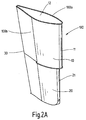
- the rudder blade 100 according to Fig. 2A . 2 B and 3 has two superimposed rudder sections 10, 20, the propeller 220 facing front nose strips 11, 31 are offset such that the one nose strip 11 are offset to port BB and the other nose strip 21 to starboard SB.
- the two side wall surfaces 100a, 100b of the rudder blade 100 merge into an end bar 30 facing away from the propeller 220.
- the upper and lower rudder blade sections 10, 20 of the rudder blade 100 are formed as follows:
- the upper rudder blade section 10 has according to Fig. 4 a cross-sectional profile 12, which is formed by a front of the leading edge 11 to the end bar 30 to a maximum profile thickness 13 conically widening front cross-sectional area 14. Adjoining this front cross-sectional area 14 is a rear cross-sectional area 15, which extends to the end bar 30 and tapers to the end bar 30.
- the front cross-sectional area 14 is subdivided by a center line M1 extending in the longitudinal direction of the rudder blade 100 into two cross-sectional area sections 14a, 14b which have different sizes.
- the larger cross-sectional area section 14a lies on the port side and the smaller cross-sectional area section 14b faces the starboard side.
- the rear cross-sectional area 15 is also divided from the center line M1 into two cross-sectional area portions 15a, 15b.
- the two cross-sectional surface portions 15a, 15b are the same size and have the same shapes.
- the two propeller-side cross-sectional surface sections 14a, 14b of the cross-sectional profile 12 of the upper rudder blade section 10 have edge regions 16, 16a with a flat curved path 16'a, wherein the two cross-sectional surface sections 15a, 15b of the cross-sectional profile 12 of the upper rudder blade section 10 facing away from the propeller 220 have tangentially extending edge regions 17 17a.
- the cross-sectional area section 14b with the edge region 16a with a strongly arched curve 16'a is located on the starboard side.
- the lower rudder blade section 20 has according to Fig. 5 a mirrored cross-sectional profile 22.
- This cross-sectional profile 20 extends from a cross-sectional area conically widening from the front leading edge 21 to the end strip 30 and up to a maximum profile thickness 23.
- Adjoining this front cross-sectional area 24 is a cross-sectional area 25 extending to the end bar 30, which tapers to the end bar 30.
- the front cross-sectional area 24 is subdivided by a center line M2 extending in the longitudinal direction of the rudder blade 100 into two cross-sectional area sections 24a, 24b which have different sizes.
- the larger cross-sectional area section 24b is located on the starboard side and the small cross-sectional area section 24a faces the port side.
- the rear cross-sectional area 25 is also divided from the center line M2 into two cross-sectional area portions 25a, 25b.
- the two cross-sectional surface portions 25a, 25b are the same size and have the same
- the two propeller-side cross-sectional surface sections 24a, 24b of the cross-sectional profile 22 of the upper rudder blade section 20 have edge regions 26, 26a with a flat arc 26 'and a curved arc 26'a, the two facing away from the propeller 220 cross-sectional surfaces 25a, 25b of the cross-sectional profile 22 of the lower Ruderblattabiteses 20 tangentially extending edge regions 27, 27a have.
- the cross-sectional surface portion 24b with the edge region 26'a with a strongly arched arc curve 26'a is located on the port side.
- the design and arrangement of the two rudder blade sections 10, 20 provides that the propeller 220 associated nose strip 11 of the upper rudder blade section 10 port side to the center line M1 and the nose strip 21 of the lower rudder blade section 20 starboard side lying to the center line M2, wherein the two rudder blade sections 10, 20th in the rear region of the rudder blade 100 are brought together in an end strip 30.
- Fig. 2A . 2 B . 3, 4 and 5 are the two rudder blade sections 10, 20 of the rudder blade 100 with their cross-sectional profiles 12, 22 arranged to each other such that the side wall portions of the rudder blade, which are in the region of the highly curved arc curves 16'a and 26'a the cross-sectional surface portions 14b and 24b starboard side and port side, then the cross-sectional surface portion 14b of the cross-sectional profile 12 of the starboard side and the cross-sectional surface portion 24b of the cross-sectional profile 22 of the port side are facing, so that the nose strips 11, 21 of the two rudder blade sections 10, 20 are port side and starboard side.
- the invention also includes an embodiment of the rudder, according to which the two rudder blade sections 10, 20 of the rudder blade 100 are arranged with their cross-sectional profiles 12, 22 to each other such that the side wall portions of the rudder blade, in the region of the highly curved arc curves 16'a and 26'a of the cross-sectional surface portions 14b and 24b are port side and starboard side, in which case the cross-sectional surface portion 14b of the port side cross-sectional profile 12 and the cross-sectional surface portion 24b of the starboard cross-sectional profile 22 are facing, so that the nose strips 11, 21 of the two rudder blade sections 10, 20 are starboard side and port side.
- a hull 120 a rudder box bearing, 100 a rudder blade and 140 denotes a rudder stock.
- a fin 135 is hinged.
- the rudder blade 100 has a preferably cylindrical recess 155 for receiving the free end of the rudder trunk bearing 120.
- the rudder trunk bearing 120 is provided as a cantilever with a central inner longitudinal bore 125 for receiving the rudder stock 140 for the rudder blade 100.
- the rudder trunk bearing 120 is sufficiently formed to the rudder blade 100 connected to the rudder end.
- the rudder trunk bearing 120 In its inner bore 125, the rudder trunk bearing 120 has a bearing 150 for supporting the rudder stock 140, wherein preferably this bearing 150 is arranged in the lower end region 120b of the rudder trunk bearing 120.
- the rudder stock 140 is led out with its end 140b with a section 145 from the rudder trunk bearing 120.
- this extended portion 145 of the rudder stock 140 is fixedly connected to the rudder blade 100 at 170, but here too a connection is provided which allows a release of the rudder blade 100 of the rudder stock 140 when the propeller shaft is to be replaced.
- the connection of the rudder stock 140 in the area 170 with the rudder blade 100 is above the propeller shaft center 200, so that only the rudder blade 100 must be removed from the rudder stock 140 for the expansion of the propeller shaft, while pulling out the rudder stock 140 from the rudder trunk 120 not is necessary, since both the free lower end 120b of the rudder trunk bearing 120 and the free lower end of the rudder stock 140 are above the propeller shaft center.
- both the free lower end 120b of the rudder trunk bearing 120 and the free lower end of the rudder stock 140 are above the propeller shaft center.
- a single inner bearing 150 is provided for the storage of the rudder stock 140 in the rudder trunk bearing 120; a further bearing for the rudder blade 100 on the outer wall of the rudder trunk bearing 120 is omitted.
- the rudder blade 100 is provided with a recess or recess indicated at 160.
- the rudder trunk bearing 120 is provided as a cantilever with a central inner longitudinal bore 125 for receiving the rudder stock 140 for the rudder blade 100. Furthermore, the rudder trunk bearing 120 is formed reaching into the rudder blade 100 connected in the rudder end and has in its inner bore 125 a bearing 150 for supporting the rudder stock 140 in the rudder trunk bearing 120. With its free end 120 b, the rudder trunk bearing 120 extends into a recess 160 in the rudder blade 100, the rudder stock 140 being led out of the rudder trunk bearing 120 in its end region 140 b with a section 145.
- this extended portion 145 of the rudder stock 140 is connected to the rudder blade 100, wherein the connection of the rudder stock 140 with the rudder blade 100 above the propeller shaft center 200 is lying.
- the inner bearing 150 is preferably provided in the end region 120b of the rudder trunk bearing 120.
Abstract
Description
Die Erfindung betrifft eine Ruderanordnung für schnelle Schiffe mit hochbelasteten Propellern.The invention relates to a rudder arrangement for fast ships with highly loaded propellers.
Schiffsruder, wie Vollschwebe-Ruder oder Balance-Profilruder, mit oder ohne angelenkter Flosse, sind in den verschiedensten Ausführungsformen bekannt.Ship rudders, such as full-floating rudder or balance rudder, with or without hinged fin, are known in various embodiments.
Die
Die
Nach der
Die
Die
Es ist Aufgabe der Erfindung, eine Ruderanordnung für schnelle Schiffe mit hochbelasteten Propellern zu schaffen, bei der Erosionserscheinungen am Ruder durch Kavitationsbildung vermieden werden.It is an object of the invention to provide a rudder assembly for fast ships with highly loaded propellers, are avoided in the erosion phenomena at the rudder by cavitation.
Gelöst wird diese Aufgabe bei einer Ruderanordnung gemäß der eingangs beschriebenen Art mit den im Anspruch 1 angegebenen Merkmalen.This object is achieved in a rudder assembly according to the type described above with the features specified in
Hiernach weist die Ruderanordnung für schnelle Schiffe ein Ruder bestehend aus einem Ruderblatt und einem dem Ruder zugeordneten, auf einer antreibbaren Propellerachse angeordneten Propeller, auf. Ferner besteht das Ruderblatt aus nur zwei übereinanderliegenden Ruderblattabschnitten, deren dem Propeller zugekehrten, ein abgerundetes Profil aufweisenden, vorderen Nasenleisten derart zueinander versetzt sind, dass die eine Nasenleiste nach Backbord oder Steuerbord und die andere Nasenleiste nach Steuerbord oder Backbord versetzt sind, wobei die beiden Seitenwandflächen des Ruderblattes in eine dem Propeller abgewandte Endleiste zusammenlaufen. Weiterhin weist die Ruderanordnung eine Flosse auf, die an das Ruderblatt im Bereich der Endleiste angelenkt ist.Hereinafter, the rudder assembly for fast ships an oar consisting of a rudder blade and a rudder associated, arranged on a drivable propeller propeller, on. Further, the rudder blade consists of only two superimposed rudder blade sections, the propeller facing, a rounded profile having front nose strips are offset from each other such that the one nose bar to port or starboard and the other nose bar are offset to starboard or port side, the two side panels of the rudder blade converge in an end bar facing away from the propeller. Furthermore, the rudder assembly on a fin, which is articulated to the rudder blade in the region of the end bar.
Der Vorteil einer derart ausgebildeten Ruderanordnung mit zwei spiegelverkehrten Querschnittsprofilen besteht zum einen in der Verhinderung der Dampfblasenbildung und zum anderen in der Verhinderung von Erosionserscheinungen an der Ruderanordnung bzw. am Ruder, die durch Kavitationsbildung bei schnellen Schiffen mit hochbelasteten Propellern auftritt. Neben einem erheblichen Kavitationsschutz ist auch eine Verbesserung des Wirkungsgrades gegeben. Eine gravierende Gewichtseinsparung wird erreicht.The advantage of such a trained rudder assembly with two mirror-inverted cross-sectional profiles on the one hand in the prevention of vapor formation and on the other in the prevention of erosion at the rudder assembly or at the rudder, which occurs by cavitation in fast ships with highly loaded propellers. In addition to a significant cavitation protection and an improvement in the efficiency is given. A serious weight saving is achieved.
Dadurch, dass die Nasenleisten der beiden Ruderblattabschnitte zueinander versetzt sind, so dass die Nasenleiste des oberen Ruderblattabschnittes nach Backbord und die Nasenleiste des unteren Ruderblattabschnittes nach Steuerbord oder die Nasenleiste des oberen Ruderblattabschnittes nach Steuerbord und die Nasenleiste des unteren Ruderblattabschnittes nach Backbord versetzt sind, werden jeweils zwei zueinander spiegelverkehrte Querschnittsprofile der beiden Ruderblattabschnitte erhalten.Characterized in that the nose strips of the two rudder blade sections are offset from each other, so that the nose strip of the upper rudder blade section to port and the nose strip of the lower rudder blade section to starboard or the nose strip of the upper rudder blade section to starboard and the nose strip of the lower rudder blade section are offset to port, respectively obtained two mutually mirror-inverted cross-sectional profiles of the two rudder blade sections.
Ferner weist die Ruderanordnung einen Ruderschaft und ein Ruderkokerlager auf. Das Ruderkokerlager ist als Kragträger mit einer mittigen Innenlängsbohrung zur Aufnahme des Ruderschaftes für das Ruderblatt ausgebildet und bis in das mit dem Ruderschaftende verbundene Ruderblatt hineinreichend ausgebildet ist, wobei zur Lagerung des Ruderschaftes ein einziges Lager in der Innenlängsbohrung des Ruderkokerlagers angeordnet ist, das mit seinem freien Ende in eine Ausnehmung, Einziehung o. dgl. in dem Ruderblatt hineinreicht, wobei der Ruderschaft in seinem Endbereich mit einem Abschnitt aus dem Ruderkokerlager herausgeführt und mit dem, freien, unteren Ende dieses Abschnittes mit dem Ruderblatt lösbar verbunden ist, wobei keine Lagerung zwischen dem Ruderblatt und dem Ruderkokerlager vorgesehen ist und wobei die Verbindung des Ruderschaftes mit dem Ruderblatt oberhalb der Propellerwellenmitte liegt, wobei das Innenlager für die Lagerung des Ruderschaftes in dem Ruderkokerlager im Endbereich des Ruderkokerlagers angeordnet ist.Furthermore, the rudder assembly on a rudder stock and a rudder koker camp. The rudder trunk bearing is designed as a cantilever beam with a central inner longitudinal bore for receiving the rudder stock for the rudder blade and extending into the rudder end connected to the rudder blade, wherein for storage of the rudder stock a single bearing is arranged in the inner longitudinal bore of the rudder trunk bearing, with its free End in a recess, collection o. The like. In the rudder blade extends, wherein the rudder stock is led out in its end with a portion of the rudder trunk bearing and releasably connected to the, free, lower end of this section with the rudder blade, with no storage between the rudder blade and the rudder trunk bearing is provided and the connection of the rudder stock with the rudder blade is above the propeller shaft center, the inner bearing is arranged for the storage of the rudder stock in the rudder trunk in the end of the rudder trunk bearing.
Der Vorteil, der sich bei einer derart ausgebildeten Ruderanordnung ergibt, bei der der Ruderschaft im Endbereich des Ruderkokerlagers mittels eines Lagers gelagert ist, wobei die Verbindung des Ruderschaftes mit dem Ruderblatt oberhalb der Propellerwellenmitte liegend ist, ohne dass es hierbei eines weiteren Lagers für das Ruderblatt an der Außenwandfläche des Ruderkokerlagers bedarf, besteht darin, dass für das Auswechseln der Propellerwelle der Ruderschaft nach der Abnahme des Ruderblattes aus dem Ruderkokerlager nicht mehr herausgezogen zu werden braucht, da die Verbindung des Ruderschaftes mit dem Ruderblatt oberhalb der Propellerwellenmitte liegt. Hinzukommt, dass das Ruderblatt des Ruders ein sehr schlankes Profil aufweisen kann.The advantage that results in such a trained rudder assembly, in which the rudder stock is mounted in the end of the rudder trunk bearing by means of a bearing, the connection of the rudder stock is located with the rudder blade above the propeller shaft center, without there being another bearing for the rudder blade is required on the outer wall surface of the rudder rod bearing, is that for the replacement of the propeller shaft of the rudder post after removal of the rudder blade from the rudder trunk need not be pulled out because the connection of the rudder stock with the rudder blade is above the propeller shaft center. In addition, the rudder blade of the rudder can have a very slim profile.
Ferner ist bei der Ruderanordnung vorgesehen, dass der obere Ruderblattabschnitt des Ruderblattes ein Querschnittsprofil aufweist, das von einer sich von der vorderen Nasenleiste bis zur rückwärtigen Endleiste erstreckenden und sich bis zu einer größten Profildicke konisch sich erweiternden vorderen Querschnittsfläche sowie einer sich an die vordere Querschnittsfläche anschließenden und sich zur rückwärtigen Endleiste konisch sich verjüngenden rückwärtigen Querschnittsfläche gebildet wird, wobei die beiden von einer in Längsrichtung des Ruderblattes verlaufenden Mittellinie gebildeten vorderenFurthermore, it is provided in the rudder arrangement that the upper rudder blade portion of the rudder blade has a cross-sectional profile extending from a front of the leading edge bead extending to the rear end strip and up to a maximum profile thickness conically expanding front cross-sectional area and adjoining the front cross-sectional area and is formed to the rear end bar conically tapered rear cross-sectional area, wherein the two formed by a running in the longitudinal direction of the rudder blade center line
Querschnittsflächenabschnitt unterschiedliche Größen aufweisen, von denen der größere Querschnittsflächenabschnitt backbordseitig liegend ist und der kleinere Querschnittsflächenabschnitt steuerbordseitig liegend ist, wobei die beiden von der Mittellinie im rückwärtigen Bereich des Querschnittsprofils gebildeten Querschnittsflächenabschnitt gleich ausgebildet sind, und dass der untere Ruderblattabschnitt des Ruderblattes ein Querschnittsprofil aufweist, das von einer sich von der vorderen Nasenleiste bis zur rückwärtigen Endleiste erstreckenden und sich zu einer größten Profildicke konisch sich erweiternden vorderen Querschnittsfläche sowie einer sich an die vordere Querschnittsfläche anschließenden und sich zur rückwärtigen Querschnittsfläche gebildet wird, wobei die beiden von einer in Längsrichtung des Ruderblattes verlaufenden Mittellinie gebildeten vorderen Querschnittsflächenabschnitt unterschiedliche Größen aufweisen, von denen der größere Querschnittsflächenabschnitt steuerbordseitig liegend ist und der kleinere Querschnittsflächenabschnitt backbordseitig liegend ist, wobei die beiden von der Mittellinie im rückwärtigen Bereich des Querschnittsprofils gebildeten Querschnittsflächenabschnitt gleich ausgebildet sind, so dass die dem Propeller zugeordnete Nasenleiste des oberen Ruderblattabschnittes backbordseitig der Mittellinie und die Nasenleiste des unteren Ruderblattabschnittes steuerbordseitig der Mittellinie liegend ist.Cross-sectional area portion have different sizes, of which the larger cross-sectional area portion is located on the port side and the smaller cross-sectional area is starboard side lying, wherein the two formed by the center line in the rear region of the cross-sectional profile cross-sectional area portion are the same, and that the lower rudder blade portion of the rudder blade has a cross-sectional profile, the from a front cross-sectional area extending from the leading leading edge and extending to a maximum profile thickness, and being formed adjacent to the anterior cross-sectional area and forming a rearward cross-sectional area, the two extending from a centerline extending longitudinally of the rudder leaf formed front cross-sectional area portion have different sizes, of which the larger Querschnittsf lying on the starboard side and the smaller cross-sectional area portion is located on the port side, wherein the two of the center line in the rear region of the cross-sectional profile formed cross-sectional area are the same, so that the propeller associated with the nose of the upper rudder blade section port side of the center line and the nose strip of the lower rudder blade section starboard side of the Midline is lying.
Die beiden propellerseitigen Querschnittsflächenabschnitte des Querschnittsprofils des oberen Ruderblattabschnittes weisen Randbereiche mit einem flachen Bogenverlauf und einem stark gewölbten Bogenverlauf auf, wobei die beiden dem Propeller abgekehrten Querschnittsflächenabschnitte des Querschnittsprofils des oberen Ruderblattabschnittes tangential verlaufende Randbereich aufweisen, wobei der Querschnittsflächenabschnitt mit dem Randbereich mit stark gewölbtem Bogenverlauf steuerbordseitig liegend ist.The two propeller-side cross-sectional surface portions of the cross-sectional profile of the upper rudder blade portion have edge regions with a flat arc and a highly curved arc, the two facing away from the propeller cross-sectional surface portions of the cross-sectional profile of the upper rudder blade portion tangentially extending edge region, wherein the cross-sectional surface portion with the edge region with a highly curved arc curve starboard side lying down.
Die beiden propellerseitigen Querschnittsflächenabschnitte des Querschnittsprofils des unteren Ruderblattabschnittes weisen Randbereich mit einem flachen Bogenverlauf und einem stark gewölbten Bogenverlauf auf, wobei die beiden dem Propeller abgekehrten Querschnittsflächenabschnitte des Querschnittsprofils des unteren Ruderblattabschnittes tangential verlaufende Randbereiche aufweisen, wobei der Querschnittsflächenabschnitt mit dem Randbereich mit stark gewölbtem Bogenverlauf backbordseitig liegend ist.The two propeller-side cross-sectional surface portions of the cross-sectional profile of the lower rudder blade portion have edge region with a flat arc and a highly curved arc, the two facing away from the propeller cross-sectional surface portions of the cross-sectional profile of lower rudder blade portion have tangentially extending edge regions, wherein the cross-sectional surface portion is lying on the port side with the edge region with strongly arched bow course.
Ausführungsbeispiele der Erfindung werden nachstehend anhand der Zeichnungen näher erläutert. Es zeigen:
- Fig. 1
- eine Ruderanordnung aus einem Ruderblatt mit einem Ruderschaft und mit einem dem Ruderblatt zugeordneten Propeller,
- Fig. 2A
- eine schaubildliche Ansicht des Ruderblattes,
- Fig. 2B
- eine Vorderansicht des Ruderblattes gemäß
Fig. 2A , - Fig. 3
- das Ruderblatt gemäß
Fig. 2A mit eingezeichneten Querschnittsformen im oberen Ruderblattabschnitt und im unteren Ruderblattabschnitt, - Fig. 4
- eine Ansicht von oben auf das Querschnittsprofil des oberen Ruderblattabschnittes des Ruders,
- Fig. 5
- eine Ansicht von oben auf das Querschnittsprofil des unteren Ruderblattabschnittes des Ruders,
- Fig. 6
- die Ruderanordnung mit in dem Ruderkokerlager gelagerten Ruderschaft und dem oberhalb der Propellerwellenmitte liegenden Befestigungspunkt des Ruderschaftes mit dem Ruderblatt und mit einer am Ruderblatt angelenkten Flosse,
- Fig. 7
- einen senkrechten Schnitt gemäß Linie VII-VII in
Fig. 6 , und - Fig. 8
- eine schematische Darstellung der Lageranordnung zwischen dem Ruderschaft und dem Ruderkoker.
- Fig. 1
- a rudder assembly comprising a rudder blade with a rudder stock and a propeller associated with the rudder blade;
- Fig. 2A
- a perspective view of the rudder blade,
- Fig. 2B
- a front view of the rudder blade according to
Fig. 2A . - Fig. 3
- the rudder blade according to
Fig. 2A with drawn cross-sectional shapes in the upper rudder blade section and in the lower rudder blade section, - Fig. 4
- a view from above of the cross-sectional profile of the upper rudder blade portion of the rudder,
- Fig. 5
- a view from above of the cross-sectional profile of the lower rudder blade portion of the rudder,
- Fig. 6
- the rudder assembly with rudder stock mounted in the rudder rod bearing and the attachment point of the rudder stock above the propeller shaft center with the rudder blade and with a fin hinged to the rudder blade,
- Fig. 7
- a vertical section along line VII-VII in
Fig. 6 , and - Fig. 8
- a schematic representation of the bearing assembly between the rudder stock and the rudder trunk.
Bei der in
Das Ruderblatt 100 gemäß
Der obere und der untere Ruderblattabschnitt 10, 20 des Ruderblattes 100 sind dabei wie folgt ausgebildet:The upper and lower
Der obere Ruderblattabschnitt 10 weist gemäß
Der größere Querschnittsflächenabschnitt 14a liegt dabei backbordseitig und der kleinere Querschnittsflächenabschnitt 14b ist der Steuerbordseite zugekehrt. Die rückwärtige Querschnittsfläche 15 wird ebenfalls von der Mittellinie M1 in zwei Querschnittsflächenabschnitte 15a, 15b unterteilt. Hier sind die beiden Querschnittsflächenabschnitte 15a, 15b gleich groß und weisen gleiche Formen auf.The larger
Die beiden propellerseitigen Querschnittsflächenabschnitte 14a, 14b des Querschnittsprofils 12 des oberen Ruderblattabschnittes 10 weisen Randbereiche 16, 16a mit einem flachen Bogenverlauf 16'a auf, wobei die beiden dem Propeller 220 abgekehrten Querschnittsflächenabschnitte 15a, 15b des Querschnittsprofils 12 des oberen Ruderblattabschnittes 10 tangential verlaufende Randbereiche 17, 17a aufweisen.The two propeller-side
Der Querschnittsflächenabschnitt 14b mit dem Randbereich 16a mit stark gewölbtem Bogenverlauf 16'a ist steuerbordseitig liegend.The
Der untere Ruderblattabschnitt 20 weist gemäß
Die beiden propellerseitigen Querschnittsflächenabschnitte 24a, 24b des Querschnittsprofils 22 des oberen Ruderblattabschnittes 20 weisen Randbereiche 26, 26a mit einem flachen Bogenverlauf 26' und einem gewölbten Bogenverlauf 26'a auf, wobei die beiden dem Propeller 220 abgekehrten Querschnittsflächen 25a, 25b des Querschnittsprofils 22 des unteren Ruderblattabschnittes 20 tangential verlaufende Randbereiche 27, 27a aufweisen.The two propeller-side
Der Querschnittsflächenabschnitt 24b mit dem Randbereich 26'a mit stark gewölbtem Bogenverlauf 26'a ist backbordseitig liegend.The
Die Ausgestaltung und Anordnung der beiden Ruderblattabschnitte 10, 20 erbringt, dass die dem Propeller 220 zugeordnete Nasenleiste 11 des oberen Ruderblattabschnittes 10 backbordseitig zur Mittellinie M1 und die Nasenleiste 21 des unteren Ruderblattabschnittes 20 steuerbordseitig zur Mittellinie M2 liegend sind, wobei die beiden Ruderblattabschnitte 10, 20 im rückwärtigen Bereich des Ruderblattes 100 in einer Endleiste 30 zusammengeführt sind.The design and arrangement of the two
Nach den
Die Erfindung schließt jedoch auch eine Ausgestaltung des Ruders mit ein, nach der die beiden Ruderblattabschnitte 10, 20 des Ruderblattes 100 mit ihren Querschnittsprofilen 12, 22 derart zueinander angeordnet sind, dass die Seitenwandabschnitte des Ruderblattes, die im Bereich der stark gekrümmten Bogenverläufe 16'a und 26'a der Querschnittsflächenabschnitte 14b und 24b backbordseitig und steuerbordseitig liegen, wobei dann der Querschnittsflächenabschnitt 14b des Querschnittsprofils 12 der Backbordseite und der Querschnittsflächenabschnitt 24b des Querschnittsprofils 22 der Steuerbordseite zugekehrt sind, so dass die Nasenleisten 11, 21 der beiden Ruderblattabschnitte 10, 20 steuerbordseitig und backbordseitig liegen.However, the invention also includes an embodiment of the rudder, according to which the two
Bei der in
Das Ruderkokerlager 120 ist als Kragträger mit einer mittigen Innenlängsbohrung 125 zur Aufnahme des Ruderschaftes 140 für das Ruderblatt 100 versehen. Außerdem ist das Ruderkokerlager 120 bis an das mit dem Ruderschaftende verbundene Ruderblatt 100 hinreichend ausgebildet. In seiner Innenbohrung 125 weist das Ruderkokerlager 120 ein Lager 150 zur Lagerung des Ruderschaftes 140 auf, wobei vorzugsweise dieses Lager 150 im unteren Endbereich 120b des Ruderkokerlagers 120 angeordnet ist. Der Ruderschaft 140 ist mit seinem Ende 140b mit einem Abschnitt 145 aus dem Ruderkokerlager 120 herausgeführt. Das freie untere Ende dieses verlängerten Abschnittes 145 des Ruderschaftes 140 ist mit dem Ruderblatt 100 bei 170 fest verbunden, wobei jedoch auch hier eine Verbindung vorgesehen ist, die ein Lösen des Ruderblattes 100 von dem Ruderschaft 140 ermöglicht, wenn die Propellerwelle ausgetauscht werden soll. Die Verbindung des Ruderschaftes 140 im Bereich 170 mit dem Ruderblatt 100 liegt dabei oberhalb der Propellerwellenmitte 200, so dass für den Ausbau der Propellerwelle lediglich das Ruderblatt 100 von dem Ruderschaft 140 abgenommen werden muss, während dagegen ein Herausziehen des Ruderschaftes 140 aus dem Ruderkokerlager 120 nicht erforderlich ist, da sowohl das freie untere Ende 120b des Ruderkokerlagers 120 als auch das freie untere Ende des Ruderschaftes 140 oberhalb der Propellerwellenmitte liegen. Bei dieser in
Bei dem Ruder ist das Ruderkokerlager 120 als Kragträger mit einer mittigen Innenlängsbohrung 125 zur Aufnahme des Ruderschaftes 140 für das Ruderblatt 100 versehen. Des Weiteren ist das Ruderkokerlager 120 bis in das in dem Ruderschaftende verbundene Ruderblatt 100 hineinreichend ausgebildet und weist in seiner Innenbohrung 125 ein Lager 150 zur Lagerung des Ruderschaftes 140 in dem Ruderkokerlager 120 auf. Mit seinem freien Ende 120b ist das Ruderkokerlager 120 in einer Ausnehmung oder Einziehung 160 in dem Ruderblatt 100 hineinreichend, wobei der Ruderschaft 140 in seinem Endbereich 140b mit einem Abschnitt 145 aus dem Ruderkokerlager 120 herausgeführt ist. Mit dem freien Ende dieses verlängerten Abschnittes 145 ist der Ruderschaft 140 mit dem Ruderblatt 100 verbunden, wobei die Verbindung des Ruderschaftes 140 mit dem Ruderblatt 100 oberhalb der Propellerwellenmitte 200 liegend ist. Im Endbereich 120b des Ruderkokerlagers 120 ist vorzugsweise das Innenlager 150 vorgesehen.In the rudder the rudder trunk bearing 120 is provided as a cantilever with a central inner
Die Erfindung ist nicht beschränkt auf die vorangehend beschriebenen und in der Zeichnung dargestellten Ausführungsformen. Abweichungen in der Anordnung des Lagers im Bereich des Ruderkokerlagers 120 und des Ruderschaftes 140 liegen ebenso im Rahmen der Erfindung wie eine andere Ausbildung der zylindrischen Einziehung 160 im Ruderblatt 100.The invention is not limited to the embodiments described above and illustrated in the drawing. Deviations in the arrangement of the bearing in the region of the rudder trunk bearing 120 and the
Claims (1)
- Rudder assembly for high-speed ships with propellers which are subject to high loads, having a rudder composed of a rudder blade (100) and a propeller (220) which is assigned to the rudder and is arranged on a driveable propeller shaft (225), wherein the rudder blade (100) is composed of only two rudder blade sections (10, 20) lying one on top of the other, wherein the leading edges (11, 21), having a rounded profile and facing the propeller (220), of the two rudder blade sections (10, 20) are positioned in such a way that the one leading edge (11) is offset towards the port side (BB) or towards the starboard side (SB) and the other leading edge (21) is offset towards the starboard side (SB) or towards the port side (BB), wherein the two lateral wall faces of the rudder blade (100) converge in a trailing edge (30) facing away from the propeller (220), wherein the upper rudder blade section (10) has a cross-sectional profile (12) whicha.) is formed by a cross-sectional face (14) which widens conically from the leading edge, facing the propeller (220), as far as a maximum profile thickness (13) and faces the propeller (220), and whereina1.) the two cross-sectional face sections (14a; 14b) of the cross-sectional face (14), which are formed by a centre line (M1) running in the longitudinal direction of the rudder blade (100) and face the propeller (220), are of different sizes,a2.) of which cross-sectional face sections (14a; 14b) the larger cross-sectional face section (14a) is located on the port side,a3.) and the smaller cross-sectional face section (14b) is located on the starboard side,a4.) and which cross-sectional profile (12) is formed by a cross-sectional face (15) which adjoins the cross-sectional face (14) and tapers conically from the maximum profile thickness (13) to the trailing edge (30), whereina5.) the two cross-sectional face sections (15a, 15b) of the cross-sectional face (15), which are formed by the centre line (M1) in the region of the cross-sectional profile (12) facing away from the propeller (220), are of identical construction,and wherein the lower rudder blade section (20) has a cross-sectional profile (22) whichb.) is formed by a cross-sectional face (24), which widens conically from the leading edge (21) facing the propeller (220) to a maximum profile thickness (23) and faces the propeller (220), whereinb1.) the two cross-sectional face sections (24a, 24b) of the cross-sectional face (24), which are formed by a centre line (M2) which runs in the longitudinal direction of the rudder blade (100) and face the propeller (220), are of different sizes,b2.) of which cross-sectional face sections (24a, 24b) the larger cross-sectional face (24) is located on the starboard side, andb3.) the smaller cross-sectional face (24a) is located on the port side,b4.) and which cross-sectional profile (22) is formed by a cross-sectional face (25) which adjoins the cross-sectional face (24) and tapers conically from the maximum profile thickness (13) to the trailing edge (30), whereinb5.) the two cross-sectional face sections (25a, 25b) of the cross-sectional face (25), which are formed by the centre line (M2) in the region of the cross-sectional profile (22) facing away from the propeller (220), are of identical construction,with the result that the leading edge (11), facing the propeller (220), of the upper rudder blade section (10) is located on the port side with respect to the centre line (M1), and the leading edge (21) of the lower rudder blade section (20) is located on the starboard side with respect to the centre line (M2), andc.) wherein the propeller-side cross-sectional face sections (14a, 14b) of the cross-sectional profile (12) of the upper rudder blade section (10) have edge regions (16, 16a) with a flat arcuate profile (16') or a highly curved arcuate profile (16'a), wherein the two cross-sectional face sections (15a, 15b) of the cross-sectional profile (12) of the upper rudder blade section (10) which face away from the propeller (220) have tangentially extending edge regions (17, 17a), and the cross-sectional face section (14b) with the edge region (16a) with a highly curved arcuate profile (16'a) is located on the starboard side,c1.) wherein the propeller-side cross-sectional face sections (24a, 24b) of the cross-sectional profile (22) of the lower rudder blade section (20) have edge regions (26, 26a) with a flat arcuate profile (26') or a highly curved arcuate profile (26'a), wherein the two cross-sectional face sections (25a, 25b) of the cross-sectional profile (22) of the lower rudder blade section (20) which face away from the propeller (220) have tangentially extending edge regions (27, 27a), and the cross-sectional face section (24b) with the edge region (26a) with a highly curved arcuate profile (26'a) is located on the port side,characterized in thatd.) the rudder arrangement also has a fin (135) which is coupled to the rudder blade (100) in the region of the trailing edge, and in thate.) the rudder arrangement also has a rudder spindle (140) and a rudder trunk bearing (120), wherein the rudder trunk bearing (120) is embodied as a cantilever beam with a central inner longitudinal bore (125) for receiving the rudder spindle (140) for the rudder blade (100), wherein the rudder trunk bearing (120) is embodied extending into the rudder blade (100) which is connected to the end of the rudder spindle, wherein in order to mount the rudder spindle (140) a single bearing (150) is arranged in the inner longitudinal bore (125) in the lower end region of the rudder trunk bearing (120), wherein the rudder spindle (140) extends in its end region (140b) with a section (145) out of the rudder trunk bearing (120), and is detachably connected by the free, lower end of this section (145) to the rudder blade (100), wherein the connection of the rudder spindle (140) to the rudder blade (100) is located above the propeller shaft centre (200), wherein in order to receive the lower free end (120b) of the rudder trunk bearing (120) a recess or drawn-in portion (160) is provided in the rudder blade (100), and wherein no mounting means is provided between the rudder blade (100) and the rudder trunk bearing (120).
Applications Claiming Priority (2)
| Application Number | Priority Date | Filing Date | Title |
|---|---|---|---|
| DE202004006453U DE202004006453U1 (en) | 2004-04-23 | 2004-04-23 | Oars for ships |
| EP04740144A EP1626897B1 (en) | 2004-04-23 | 2004-06-22 | Rudder for ships |
Related Parent Applications (1)
| Application Number | Title | Priority Date | Filing Date |
|---|---|---|---|
| EP04740144A Division EP1626897B1 (en) | 2004-04-23 | 2004-06-22 | Rudder for ships |
Publications (3)
| Publication Number | Publication Date |
|---|---|
| EP2025593A2 EP2025593A2 (en) | 2009-02-18 |
| EP2025593A3 EP2025593A3 (en) | 2009-04-01 |
| EP2025593B1 true EP2025593B1 (en) | 2016-08-17 |
Family
ID=33441997
Family Applications (3)
| Application Number | Title | Priority Date | Filing Date |
|---|---|---|---|
| EP04740144A Revoked EP1626897B1 (en) | 2004-04-23 | 2004-06-22 | Rudder for ships |
| EP07013643.7A Active EP1857358B1 (en) | 2004-04-23 | 2004-06-22 | Rudder for ships |
| EP08015619.3A Active EP2025593B1 (en) | 2004-04-23 | 2004-06-22 | Rudder for ships |
Family Applications Before (2)
| Application Number | Title | Priority Date | Filing Date |
|---|---|---|---|
| EP04740144A Revoked EP1626897B1 (en) | 2004-04-23 | 2004-06-22 | Rudder for ships |
| EP07013643.7A Active EP1857358B1 (en) | 2004-04-23 | 2004-06-22 | Rudder for ships |
Country Status (14)
| Country | Link |
|---|---|
| EP (3) | EP1626897B1 (en) |
| JP (2) | JP4410656B2 (en) |
| KR (2) | KR20050103137A (en) |
| CN (2) | CN101016082B (en) |
| AT (1) | ATE431285T1 (en) |
| DE (8) | DE202004006453U1 (en) |
| DK (2) | DK1857358T3 (en) |
| ES (3) | ES2602562T3 (en) |
| HK (1) | HK1083813A1 (en) |
| PL (2) | PL1626897T3 (en) |
| PT (1) | PT1626897E (en) |
| SI (1) | SI1626897T1 (en) |
| TW (2) | TWI302894B (en) |
| WO (1) | WO2005113332A1 (en) |
Families Citing this family (26)
| Publication number | Priority date | Publication date | Assignee | Title |
|---|---|---|---|---|
| KR100735724B1 (en) * | 2006-06-15 | 2007-07-06 | 김효철 | Ships rudder with double acting gap flow stopper between fixed and movable part |
| DE102006047755A1 (en) * | 2006-10-06 | 2008-04-10 | Wobben, Aloys | Side ship rudder |
| KR100899737B1 (en) * | 2007-10-29 | 2009-05-27 | 대우조선해양 주식회사 | Full spade rudder with twisted leading edge having a small rudder bulb |
| DE202007015941U1 (en) † | 2007-11-13 | 2008-01-17 | Becker Marine Systems Gmbh & Co. Kg | Oars for ships |
| DE502008000400D1 (en) * | 2007-11-13 | 2010-04-08 | Becker Marine Sys Gmbh & Co Kg | Rudder arrangement for ships at higher speeds with a cavitation-reducing, twisted, in particular Vollschweberuder |
| DE202007016164U1 (en) * | 2007-11-16 | 2008-01-24 | Becker Marine Systems Gmbh & Co. Kg | High efficiency rudder for ships |
| KR101010850B1 (en) * | 2007-11-27 | 2011-01-26 | 삼성중공업 주식회사 | Asymmetric Rudder for reduced cavitation |
| CN101186233B (en) * | 2007-12-19 | 2011-05-11 | 沪东中华造船(集团)有限公司 | Method for reducing vessels stern semi-balance suspension rudder blade surface cavitation |
| CA2639804C (en) * | 2008-08-13 | 2011-02-01 | Becker Marine Systems Gmbh & Co. Kg | Rudder arrangement for ships having higher speeds comprising a cavitation-reducing twisted, in particular balanced rudder |
| EP2154064B1 (en) | 2008-08-13 | 2012-04-11 | becker marine systems GmbH & Co. KG | Rudder assembly for ships with high speeds with a cavitation reducing, twisted, in particular floating rudder |
| KR100958075B1 (en) * | 2009-04-15 | 2010-05-14 | 대우조선해양 주식회사 | Full spade rudder with twisted leading edge having a small rudder bulb |
| KR100903066B1 (en) * | 2009-04-15 | 2009-06-18 | 대우조선해양 주식회사 | Full spade rudder with twisted leading edge having a small rudder bulb |
| KR100903067B1 (en) * | 2009-04-16 | 2009-06-18 | 대우조선해양 주식회사 | Full spade rudder with twisted leading edge having a small rudder bulb |
| KR100901393B1 (en) * | 2009-04-17 | 2009-06-05 | 대우조선해양 주식회사 | Full spade rudder with twisted leading edge having a small rudder bulb |
| ATE555981T1 (en) | 2009-06-17 | 2012-05-15 | Daewoo Shipbuilding & Marine | SHIP'S OAR |
| KR200447816Y1 (en) * | 2009-07-10 | 2010-02-23 | 대우조선해양 주식회사 | Rudder of ship |
| DE102009047244A1 (en) * | 2009-11-27 | 2011-06-01 | Van Der Velden Barkemeyer Gmbh | Method and connecting device for connecting a rudder or propeller shaft with a driving or driven assembly of a ship |
| NO336848B1 (en) * | 2013-03-08 | 2015-11-16 | Rolls Royce Marine As Rudders | rudder device |
| NO336378B1 (en) * | 2013-06-20 | 2015-08-10 | Rolls Royce Marine As Rudders | rudder device |
| CN105416554B (en) * | 2015-12-24 | 2017-09-29 | 九成投资集团有限公司 | With rudder blade from song to guide margin |
| CN105438430A (en) * | 2015-12-24 | 2016-03-30 | 大连船舶重工集团舵轴有限公司 | Curved guide suspension rudder |
| JP6582296B2 (en) * | 2016-03-31 | 2019-10-02 | 三井E&S造船株式会社 | Ship rudder and ship |
| CN106985993B (en) * | 2017-03-17 | 2019-01-04 | 绍兴开源机电科技有限公司 | A kind of combined type ship rudder blade |
| JP7148329B2 (en) * | 2018-09-03 | 2022-10-05 | 住友重機械マリンエンジニアリング株式会社 | Rudder blades and ships |
| CN110723263B (en) * | 2019-09-17 | 2020-07-14 | 广州文冲船舶修造有限公司 | Ship rudder blade refitting process |
| CN111746749A (en) * | 2020-06-22 | 2020-10-09 | 沪东中华造船(集团)有限公司 | Rudder propeller matching system |
Citations (1)
| Publication number | Priority date | Publication date | Assignee | Title |
|---|---|---|---|---|
| DE8708276U1 (en) * | 1987-06-12 | 1987-08-27 | Willi Becker Ingenieurbuero Gmbh, 2000 Hamburg, De |
Family Cites Families (11)
| Publication number | Priority date | Publication date | Assignee | Title |
|---|---|---|---|---|
| DE516085C (en) * | 1931-01-17 | Max Oertz Dr Ing | Streamlined rudder behind the ship's drive | |
| GB330282A (en) * | 1928-11-10 | 1930-06-04 | Goodyear Tire & Rubber | Vehicle tyre |
| GB332082A (en) * | 1929-08-07 | 1930-07-17 | Amos Lowrey Ayre | Improvements in ships' rudders |
| DE2834015C2 (en) * | 1978-08-03 | 1980-07-03 | Howaldtswerke-Deutsche Werft Ag Hamburg Und Kiel, 2300 Kiel | Rowing training for ships |
| DE8016289U1 (en) * | 1980-06-20 | 1980-10-02 | Mti Manoevriertechnisches Institut Gmbh, 2000 Hamburg | OARS FOR WATER VEHICLES AND FLOATING UNIT |
| JPS5816996A (en) * | 1981-07-22 | 1983-01-31 | Ishikawajima Harima Heavy Ind Co Ltd | Rudder |
| JPS5830896A (en) * | 1981-08-18 | 1983-02-23 | Ishikawajima Harima Heavy Ind Co Ltd | Reaction rudder without discontinuous part |
| DE4426953B4 (en) * | 1994-07-29 | 2005-09-22 | Tbi Technologie-Beratungs-Institut Gmbh | Rudder or rudder nozzle with hinged fin for watercraft |
| DE29609745U1 (en) * | 1996-06-04 | 1996-08-29 | Becker Ingbuero W | Rudder for seagoing ships |
| KR100346512B1 (en) | 1999-07-07 | 2002-08-01 | 삼성중공업 주식회사 | A rudder of ship |
| NL1015629C2 (en) * | 2000-07-06 | 2002-01-11 | A Van Der Velden B V | Ship's rudder has horizontal top and bottom plates and sinusoidal shaped variation between upper and lower plates |
-
2004
- 2004-04-23 DE DE202004006453U patent/DE202004006453U1/en not_active Expired - Lifetime
- 2004-06-22 SI SI200431117T patent/SI1626897T1/en unknown
- 2004-06-22 PL PL04740144T patent/PL1626897T3/en unknown
- 2004-06-22 PL PL07013643T patent/PL1857358T3/en unknown
- 2004-06-22 WO PCT/EP2004/006713 patent/WO2005113332A1/en not_active Application Discontinuation
- 2004-06-22 DE DE202004021222U patent/DE202004021222U1/en not_active Expired - Lifetime
- 2004-06-22 EP EP04740144A patent/EP1626897B1/en not_active Revoked
- 2004-06-22 EP EP07013643.7A patent/EP1857358B1/en active Active
- 2004-06-22 EP EP08015619.3A patent/EP2025593B1/en active Active
- 2004-06-22 DK DK07013643.7T patent/DK1857358T3/en active
- 2004-06-22 ES ES08015619.3T patent/ES2602562T3/en active Active
- 2004-06-22 ES ES07013643.7T patent/ES2604756T3/en active Active
- 2004-06-22 ES ES04740144T patent/ES2323784T3/en active Active
- 2004-06-22 DE DE202004021218U patent/DE202004021218U1/en not_active Expired - Lifetime
- 2004-06-22 DE DE502004009484T patent/DE502004009484D1/en active Active
- 2004-06-22 PT PT04740144T patent/PT1626897E/en unknown
- 2004-06-22 DE DE202004021495U patent/DE202004021495U1/en not_active Expired - Lifetime
- 2004-06-22 DK DK04740144T patent/DK1626897T3/en active
- 2004-06-22 DE DE202004021474U patent/DE202004021474U1/en not_active Expired - Lifetime
- 2004-06-22 DE DE202004021223U patent/DE202004021223U1/en not_active Expired - Lifetime
- 2004-06-22 DE DE202004021604U patent/DE202004021604U1/en not_active Expired - Lifetime
- 2004-06-22 AT AT04740144T patent/ATE431285T1/en not_active IP Right Cessation
- 2004-10-21 TW TW096110096A patent/TWI302894B/en active
- 2004-10-21 TW TW093131982A patent/TWI295982B/en active
- 2004-10-28 KR KR1020040086554A patent/KR20050103137A/en not_active Application Discontinuation
- 2004-10-29 CN CN2007100052561A patent/CN101016082B/en active Active
- 2004-10-29 CN CNB2004100901610A patent/CN100351143C/en active Active
- 2004-10-29 JP JP2004316211A patent/JP4410656B2/en active Active
-
2006
- 2006-03-24 HK HK06103725A patent/HK1083813A1/en unknown
-
2007
- 2007-01-18 JP JP2007009039A patent/JP4597146B2/en active Active
-
2009
- 2009-03-02 KR KR1020090017636A patent/KR20090029249A/en not_active Application Discontinuation
Patent Citations (1)
| Publication number | Priority date | Publication date | Assignee | Title |
|---|---|---|---|---|
| DE8708276U1 (en) * | 1987-06-12 | 1987-08-27 | Willi Becker Ingenieurbuero Gmbh, 2000 Hamburg, De |
Also Published As
Similar Documents
| Publication | Publication Date | Title |
|---|---|---|
| EP2025593B1 (en) | Rudder for ships | |
| EP2060484B2 (en) | Rudder for ships | |
| EP2060483A1 (en) | High-performance rudder for ships | |
| EP1476353A1 (en) | Line design and propulsion system for a directionally stable, seagoing boat with rudder propeller drive system | |
| EP0837817B1 (en) | Method of sailing a boat, and sailing vessel | |
| EP1922246B1 (en) | Water craft | |
| DE583091C (en) | Guide surface rudder for watercraft and aircraft | |
| DE2610790A1 (en) | Sail watercraft with lifting foil - has aerofoil section fitted in line with centre of gravity and stabilising discs at ends | |
| EP0392019A1 (en) | High-speed vessel | |
| DE19752170C2 (en) | Buoyancy device located in the bow area of a multi-hull watercraft | |
| DE202007017450U1 (en) | High efficiency rudder for ships | |
| DE202005018180U1 (en) | High load balanced rudder | |
| DE202019102807U1 (en) | Rudder for ships and double propeller ship with two oars | |
| DE202004021500U1 (en) | Oars for ships | |
| DE3011642C2 (en) | Sailing vehicle | |
| EP0315963A1 (en) | Aerofoil sail for sailing vessels | |
| DE202017104742U1 (en) | Ship with a profile sail | |
| DE2810669A1 (en) | Adjustable centre-board for dinghy - has cable drives to alter angle and spatial setting to trim craft | |
| DE10103137A1 (en) | Ships rudder with vertical axis of rotation uses curved or angled rudder center plane varying across rudder span to overcome twist generated by submarine propeller screws. | |
| EP1448432A2 (en) | Mast system for sailing boats | |
| DE7147512U (en) | Single blade stern rudder, especially for inland watercraft | |
| DE3642908A1 (en) | Watercraft | |
| DE2609348A1 (en) | Sailing craft with pivoted mast - has universal joint at mast base to counteract heeling over | |
| DEV0006839MA (en) | ||
| DE4024479A1 (en) | Manual propulsion for surf boards - has drive delivered by shaft to pair of hinged paddles below hull |
Legal Events
| Date | Code | Title | Description |
|---|---|---|---|
| PUAI | Public reference made under article 153(3) epc to a published international application that has entered the european phase |
Free format text: ORIGINAL CODE: 0009012 |
|
| 17P | Request for examination filed |
Effective date: 20080927 |
|
| AC | Divisional application: reference to earlier application |
Ref document number: 1626897 Country of ref document: EP Kind code of ref document: P |
|
| AK | Designated contracting states |
Kind code of ref document: A2 Designated state(s): AT BE BG CH CY CZ DE DK EE ES FI FR GB GR HU IE IT LI LU MC NL PL PT RO SE SI SK TR |
|
| PUAL | Search report despatched |
Free format text: ORIGINAL CODE: 0009013 |
|
| AK | Designated contracting states |
Kind code of ref document: A3 Designated state(s): AT BE BG CH CY CZ DE DK EE ES FI FR GB GR HU IE IT LI LU MC NL PL PT RO SE SI SK TR |
|
| 17Q | First examination report despatched |
Effective date: 20091009 |
|
| RAP1 | Party data changed (applicant data changed or rights of an application transferred) |
Owner name: BECKER MARINE SYSTEMS GMBH & CO. KG |
|
| GRAP | Despatch of communication of intention to grant a patent |
Free format text: ORIGINAL CODE: EPIDOSNIGR1 |
|
| INTG | Intention to grant announced |
Effective date: 20160208 |
|
| RIN1 | Information on inventor provided before grant (corrected) |
Inventor name: LEHMANN, DIRK |
|
| GRAS | Grant fee paid |
Free format text: ORIGINAL CODE: EPIDOSNIGR3 |
|
| GRAA | (expected) grant |
Free format text: ORIGINAL CODE: 0009210 |
|
| AC | Divisional application: reference to earlier application |
Ref document number: 1626897 Country of ref document: EP Kind code of ref document: P |
|
| AK | Designated contracting states |
Kind code of ref document: B1 Designated state(s): AT BE BG CH CY CZ DE DK EE ES FI FR GB GR HU IE IT LI LU MC NL PL PT RO SE SI SK TR |
|
| REG | Reference to a national code |
Ref country code: GB Ref legal event code: FG4D Free format text: NOT ENGLISH |
|
| REG | Reference to a national code |
Ref country code: CH Ref legal event code: EP |
|
| REG | Reference to a national code |
Ref country code: IE Ref legal event code: FG4D Free format text: LANGUAGE OF EP DOCUMENT: GERMAN |
|
| REG | Reference to a national code |
Ref country code: AT Ref legal event code: REF Ref document number: 820778 Country of ref document: AT Kind code of ref document: T Effective date: 20160915 |
|
| REG | Reference to a national code |
Ref country code: DE Ref legal event code: R096 Ref document number: 502004015281 Country of ref document: DE |
|
| REG | Reference to a national code |
Ref country code: RO Ref legal event code: EPE |
|
| REG | Reference to a national code |
Ref country code: NL Ref legal event code: FP |
|
| REG | Reference to a national code |
Ref country code: SE Ref legal event code: TRGR |
|
| REG | Reference to a national code |
Ref country code: ES Ref legal event code: FG2A Ref document number: 2602562 Country of ref document: ES Kind code of ref document: T3 Effective date: 20170221 |
|
| PG25 | Lapsed in a contracting state [announced via postgrant information from national office to epo] |
Ref country code: PT Free format text: LAPSE BECAUSE OF FAILURE TO SUBMIT A TRANSLATION OF THE DESCRIPTION OR TO PAY THE FEE WITHIN THE PRESCRIBED TIME-LIMIT Effective date: 20161219 Ref country code: PL Free format text: LAPSE BECAUSE OF FAILURE TO SUBMIT A TRANSLATION OF THE DESCRIPTION OR TO PAY THE FEE WITHIN THE PRESCRIBED TIME-LIMIT Effective date: 20160817 |
|
| RAP2 | Party data changed (patent owner data changed or rights of a patent transferred) |
Owner name: BECKER MARINE SYSTEMS GMBH |
|
| REG | Reference to a national code |
Ref country code: GR Ref legal event code: EP Ref document number: 20160402868 Country of ref document: GR Effective date: 20170222 |
|
| PG25 | Lapsed in a contracting state [announced via postgrant information from national office to epo] |
Ref country code: EE Free format text: LAPSE BECAUSE OF FAILURE TO SUBMIT A TRANSLATION OF THE DESCRIPTION OR TO PAY THE FEE WITHIN THE PRESCRIBED TIME-LIMIT Effective date: 20160817 |
|
| REG | Reference to a national code |
Ref country code: DE Ref legal event code: R097 Ref document number: 502004015281 Country of ref document: DE |
|
| PG25 | Lapsed in a contracting state [announced via postgrant information from national office to epo] |
Ref country code: SK Free format text: LAPSE BECAUSE OF FAILURE TO SUBMIT A TRANSLATION OF THE DESCRIPTION OR TO PAY THE FEE WITHIN THE PRESCRIBED TIME-LIMIT Effective date: 20160817 Ref country code: CZ Free format text: LAPSE BECAUSE OF FAILURE TO SUBMIT A TRANSLATION OF THE DESCRIPTION OR TO PAY THE FEE WITHIN THE PRESCRIBED TIME-LIMIT Effective date: 20160817 Ref country code: DK Free format text: LAPSE BECAUSE OF FAILURE TO SUBMIT A TRANSLATION OF THE DESCRIPTION OR TO PAY THE FEE WITHIN THE PRESCRIBED TIME-LIMIT Effective date: 20160817 Ref country code: BG Free format text: LAPSE BECAUSE OF FAILURE TO SUBMIT A TRANSLATION OF THE DESCRIPTION OR TO PAY THE FEE WITHIN THE PRESCRIBED TIME-LIMIT Effective date: 20161117 |
|
| REG | Reference to a national code |
Ref country code: FR Ref legal event code: PLFP Year of fee payment: 14 |
|
| PLBE | No opposition filed within time limit |
Free format text: ORIGINAL CODE: 0009261 |
|
| STAA | Information on the status of an ep patent application or granted ep patent |
Free format text: STATUS: NO OPPOSITION FILED WITHIN TIME LIMIT |
|
| 26N | No opposition filed |
Effective date: 20170518 |
|
| PG25 | Lapsed in a contracting state [announced via postgrant information from national office to epo] |
Ref country code: SI Free format text: LAPSE BECAUSE OF FAILURE TO SUBMIT A TRANSLATION OF THE DESCRIPTION OR TO PAY THE FEE WITHIN THE PRESCRIBED TIME-LIMIT Effective date: 20160817 |
|
| PG25 | Lapsed in a contracting state [announced via postgrant information from national office to epo] |
Ref country code: MC Free format text: LAPSE BECAUSE OF FAILURE TO SUBMIT A TRANSLATION OF THE DESCRIPTION OR TO PAY THE FEE WITHIN THE PRESCRIBED TIME-LIMIT Effective date: 20160817 |
|
| REG | Reference to a national code |
Ref country code: CH Ref legal event code: PL |
|
| REG | Reference to a national code |
Ref country code: IE Ref legal event code: MM4A |
|
| PG25 | Lapsed in a contracting state [announced via postgrant information from national office to epo] |
Ref country code: CH Free format text: LAPSE BECAUSE OF NON-PAYMENT OF DUE FEES Effective date: 20170630 Ref country code: LU Free format text: LAPSE BECAUSE OF NON-PAYMENT OF DUE FEES Effective date: 20170622 Ref country code: IE Free format text: LAPSE BECAUSE OF NON-PAYMENT OF DUE FEES Effective date: 20170622 Ref country code: LI Free format text: LAPSE BECAUSE OF NON-PAYMENT OF DUE FEES Effective date: 20170630 |
|
| REG | Reference to a national code |
Ref country code: BE Ref legal event code: MM Effective date: 20170630 |
|
| REG | Reference to a national code |
Ref country code: DE Ref legal event code: R082 Ref document number: 502004015281 Country of ref document: DE Representative=s name: RGTH RICHTER GERBAULET THIELEMANN HOFMANN PATE, DE Ref country code: FR Ref legal event code: PLFP Year of fee payment: 15 Ref country code: DE Ref legal event code: R081 Ref document number: 502004015281 Country of ref document: DE Owner name: BECKER MARINE SYSTEMS GMBH, DE Free format text: FORMER OWNER: BECKER MARINE SYSTEMS GMBH & CO. KG, 21079 HAMBURG, DE |
|
| REG | Reference to a national code |
Ref country code: AT Ref legal event code: MM01 Ref document number: 820778 Country of ref document: AT Kind code of ref document: T Effective date: 20170622 |
|
| PG25 | Lapsed in a contracting state [announced via postgrant information from national office to epo] |
Ref country code: BE Free format text: LAPSE BECAUSE OF NON-PAYMENT OF DUE FEES Effective date: 20170630 |
|
| PG25 | Lapsed in a contracting state [announced via postgrant information from national office to epo] |
Ref country code: AT Free format text: LAPSE BECAUSE OF NON-PAYMENT OF DUE FEES Effective date: 20170622 |
|
| PG25 | Lapsed in a contracting state [announced via postgrant information from national office to epo] |
Ref country code: HU Free format text: LAPSE BECAUSE OF FAILURE TO SUBMIT A TRANSLATION OF THE DESCRIPTION OR TO PAY THE FEE WITHIN THE PRESCRIBED TIME-LIMIT; INVALID AB INITIO Effective date: 20040622 |
|
| PG25 | Lapsed in a contracting state [announced via postgrant information from national office to epo] |
Ref country code: CY Free format text: LAPSE BECAUSE OF NON-PAYMENT OF DUE FEES Effective date: 20160817 |
|
| P01 | Opt-out of the competence of the unified patent court (upc) registered |
Effective date: 20230529 |
|
| PGFP | Annual fee paid to national office [announced via postgrant information from national office to epo] |
Ref country code: RO Payment date: 20230608 Year of fee payment: 20 Ref country code: NL Payment date: 20230620 Year of fee payment: 20 Ref country code: FR Payment date: 20230620 Year of fee payment: 20 |
|
| PGFP | Annual fee paid to national office [announced via postgrant information from national office to epo] |
Ref country code: TR Payment date: 20230616 Year of fee payment: 20 Ref country code: SE Payment date: 20230622 Year of fee payment: 20 Ref country code: GR Payment date: 20230616 Year of fee payment: 20 Ref country code: FI Payment date: 20230621 Year of fee payment: 20 |
|
| PGFP | Annual fee paid to national office [announced via postgrant information from national office to epo] |
Ref country code: IT Payment date: 20230630 Year of fee payment: 20 Ref country code: GB Payment date: 20230622 Year of fee payment: 20 Ref country code: ES Payment date: 20230719 Year of fee payment: 20 |
|
| PGFP | Annual fee paid to national office [announced via postgrant information from national office to epo] |
Ref country code: DE Payment date: 20230718 Year of fee payment: 20 |