EP2025110B1 - Method and apparatus for controlling energy consumption of sensor network nodes - Google Patents
Method and apparatus for controlling energy consumption of sensor network nodes Download PDFInfo
- Publication number
- EP2025110B1 EP2025110B1 EP07735554.3A EP07735554A EP2025110B1 EP 2025110 B1 EP2025110 B1 EP 2025110B1 EP 07735554 A EP07735554 A EP 07735554A EP 2025110 B1 EP2025110 B1 EP 2025110B1
- Authority
- EP
- European Patent Office
- Prior art keywords
- node
- information
- data transmission
- energy
- data
- Prior art date
- Legal status (The legal status is an assumption and is not a legal conclusion. Google has not performed a legal analysis and makes no representation as to the accuracy of the status listed.)
- Active
Links
Images


Classifications
-
- H—ELECTRICITY
- H04—ELECTRIC COMMUNICATION TECHNIQUE
- H04L—TRANSMISSION OF DIGITAL INFORMATION, e.g. TELEGRAPHIC COMMUNICATION
- H04L1/00—Arrangements for detecting or preventing errors in the information received
- H04L1/12—Arrangements for detecting or preventing errors in the information received by using return channel
- H04L1/16—Arrangements for detecting or preventing errors in the information received by using return channel in which the return channel carries supervisory signals, e.g. repetition request signals
- H04L1/18—Automatic repetition systems, e.g. Van Duuren systems
- H04L1/1867—Arrangements specially adapted for the transmitter end
- H04L1/188—Time-out mechanisms
-
- G—PHYSICS
- G01—MEASURING; TESTING
- G01D—MEASURING NOT SPECIALLY ADAPTED FOR A SPECIFIC VARIABLE; ARRANGEMENTS FOR MEASURING TWO OR MORE VARIABLES NOT COVERED IN A SINGLE OTHER SUBCLASS; TARIFF METERING APPARATUS; MEASURING OR TESTING NOT OTHERWISE PROVIDED FOR
- G01D3/00—Indicating or recording apparatus with provision for the special purposes referred to in the subgroups
-
- H—ELECTRICITY
- H04—ELECTRIC COMMUNICATION TECHNIQUE
- H04W—WIRELESS COMMUNICATION NETWORKS
- H04W40/00—Communication routing or communication path finding
- H04W40/02—Communication route or path selection, e.g. power-based or shortest path routing
- H04W40/04—Communication route or path selection, e.g. power-based or shortest path routing based on wireless node resources
- H04W40/10—Communication route or path selection, e.g. power-based or shortest path routing based on wireless node resources based on available power or energy
-
- H—ELECTRICITY
- H04—ELECTRIC COMMUNICATION TECHNIQUE
- H04W—WIRELESS COMMUNICATION NETWORKS
- H04W40/00—Communication routing or communication path finding
- H04W40/24—Connectivity information management, e.g. connectivity discovery or connectivity update
- H04W40/246—Connectivity information discovery
-
- H—ELECTRICITY
- H04—ELECTRIC COMMUNICATION TECHNIQUE
- H04W—WIRELESS COMMUNICATION NETWORKS
- H04W52/00—Power management, e.g. TPC [Transmission Power Control], power saving or power classes
- H04W52/02—Power saving arrangements
- H04W52/0209—Power saving arrangements in terminal devices
- H04W52/0261—Power saving arrangements in terminal devices managing power supply demand, e.g. depending on battery level
-
- H—ELECTRICITY
- H04—ELECTRIC COMMUNICATION TECHNIQUE
- H04L—TRANSMISSION OF DIGITAL INFORMATION, e.g. TELEGRAPHIC COMMUNICATION
- H04L1/00—Arrangements for detecting or preventing errors in the information received
- H04L1/0001—Systems modifying transmission characteristics according to link quality, e.g. power backoff
-
- H—ELECTRICITY
- H04—ELECTRIC COMMUNICATION TECHNIQUE
- H04W—WIRELESS COMMUNICATION NETWORKS
- H04W84/00—Network topologies
- H04W84/18—Self-organising networks, e.g. ad-hoc networks or sensor networks
-
- Y—GENERAL TAGGING OF NEW TECHNOLOGICAL DEVELOPMENTS; GENERAL TAGGING OF CROSS-SECTIONAL TECHNOLOGIES SPANNING OVER SEVERAL SECTIONS OF THE IPC; TECHNICAL SUBJECTS COVERED BY FORMER USPC CROSS-REFERENCE ART COLLECTIONS [XRACs] AND DIGESTS
- Y02—TECHNOLOGIES OR APPLICATIONS FOR MITIGATION OR ADAPTATION AGAINST CLIMATE CHANGE
- Y02D—CLIMATE CHANGE MITIGATION TECHNOLOGIES IN INFORMATION AND COMMUNICATION TECHNOLOGIES [ICT], I.E. INFORMATION AND COMMUNICATION TECHNOLOGIES AIMING AT THE REDUCTION OF THEIR OWN ENERGY USE
- Y02D30/00—Reducing energy consumption in communication networks
- Y02D30/70—Reducing energy consumption in communication networks in wireless communication networks
Definitions
- This invention is related to a wireless sensor network, in particular, to a method, apparatus and computer program product for controlling energy expanding of wireless sensor network nodes and to a sensor network.
- the communication capacity of sensor network is very limited; the communication bandwidth of sensors in sensor network is narrow and often varied, and the coverage range of communication is only several tens meters to hundreds meters. If the data transmission exceeds the available bandwidth, a high lost-packet rate will be caused.
- the power energy of sensors is very limited; a lot of energy is required in the information sensing of sensor network, data process and communication, and if the node power supply of sensor network under Batteries-Supply can not be replaced, the energy consumption it caused will directly affect the lifecycle of whole sensor network.
- Cluster head data fusion is means of reducing node energy consumption by reducing network traffic.
- sensor network usually includes a plurality of node cluster, and each node cluster includes a central node, and a sensor network is divided into a plurality of sensor sub network, so it can avoid that data communication bottleneck of transferring original data directly from each sensor node to sensor network base station.
- the operation mode based on wake-up when required between coverage node (i.e. cluster head node) and sensor node in Zigbee network can also partly solve the problem of energy supply in the sensor network.
- a plurality of sensor nodes is included in the sensor network, and data process and communication status of each sensor node is different each other, the corresponding energy consumption status is different each other.
- the radio communication device determines whether a message is destined for itself and subsequently determines a delay amount for responding or a relaying a transmission when the message is not addressed to itself. In a particular implementation the radio communication device monitors the remaining battery power, so as to enable the selection of a route through radio communication devices having more remaining battery power.
- Present invention is to provide a method and apparatus for controlling energy expanding of sensor network nodes, which are capable of efficiently utilize the network resource to save the power consumption of sensor node, and prolong the whole life of sensor network.
- a method for controlling energy expanding of a sensor network is provided according to claim 1.
- an apparatus for controlling energy expanding of a sensor network is provided according to claim 7.
- a sensor network is provided according to claim 11.
- the apparatus and method of present invention can adjust data transmission parameter of the nodes accordingly based on the energy information of the nodes, save the power consumption of sensor node, and prolong the life of sensor network, in order to more efficiently utilize the network resource.
- present invention will be described in details with respect to a method and apparatus for controlling energy expanding of sensor nodes in a wireless sensor network. It will be understood by those skilled in the art that present invention could be modified and applied in other types of network, such as Bluetooth network or Wireless Local Area Network (WLAN), on the basis of without departing the scope of content of present invention.
- Bluetooth network Wireless Local Area Network
- WLAN Wireless Local Area Network
- a node transmits data to a receiving node, and the receiving node will send back feedback information after successful receives the data, so as to acknowledge the successful data transmission. If the node that sends data does not receive any feedback information about successful data transmission in a retransmission timeout, the data will be re-sent. If the node that sends data does still not receive any feedback information about successful data transmission after re-sending, the data will be re-sent for many times, until the data are transmitted successfully. Alternatively, if it is still not successful after a certain times of re-sending, the data transmission will be given up.
- FIG. 1 is an illustrative view of a sensor network configuration in accordance with an embodiment of present invention.
- This sensor network includes a sensor network controller 110, a plurality of wireless sensor nodes 120, and a plurality of wired sensor nodes 130.
- the sensors 120 and 130 are connected to the sensor network controller 110 via wired or wireless connection, wherein the sensor network controller 110 being used to collect data, the function thereof being similar to a base station in a wireless communication network or a router in a wired communication network, or a combination of them.
- the wired communication between each sensor 120 and 130 and the sensor network controller 110 is via Local Area Network (LAN) or via dedicated communication line, and the wireless communication may adopt the Wireless Local Area Network (WLAN) or Bluetooth standard.
- the respective sensor nodes 120, 130 transmit the information of detecting result and so on to the sensor network controller 110, for example, the wired transmission shown in solid line in the figures.
- the sensor network controller 110 may also send the control signals to the respective sensors 120, 130, for example, the wired transmission shown in dashed line in the figures; which will be optimized.
- the optimization process includes determining whether the information will be transmitted through a certain sensor, adjusting the sampling rate of a certain sensor, or determining whether the data of a certain sensor will be encrypted, and so on. It could be viewed from Fig. 1 that the sensor network controller 110 is a convergent point of all the detected data, and to analysis and process the detected data, and then educe a process center of the detected results, which is also a control center of optimizing the network.
- FIG. 2 is an illustrative view of a sensor network configuration in accordance with another embodiment of present invention.
- a plurality of sensors 120 and 130 are connected to the data collector 210 via wired or wireless connection, constituting a sensor network 220.
- Distinct sensor networks 220, 230 and 240 are connected with the sensor network controller 250 via their respective data collectors.
- the sensor network controller 250 collects sensor data from the respective sensor networks 220, 230 and 240, as well as sends a control command to the respective sensor networks 220, 230 and 240.
- various optimization processes are performed to the respective sensors 120 and 130 in the networks 220, 230 and 240 by the data collector, such as 210.
- FIG 3 it is an illustrative view of functional configuration of network controller in a sensor network in accordance with an embodiment of present invention.
- the sensor network controller 300 includes an acquiring device 310 that includes an energy information acquiring device 314, and a adjusting device 320, wherein the energy information acquiring device 314 is used to acquire energy information, the energy information being indicative of the energy status of one node in the network.
- the energy information may be indicative of the power supply status of a sensor node, for instance, the power status of a node may be classified into three levels, i.e. high, middle, and low, which are expressed by the values of 3, 2, and 1 respectively.
- the adjusting device 320 is used to adjust at least one data transmission parameter of the node accordingly based on the energy information.
- the data transmission parameter may be the retransmission timeout and/or retransmission times, the retransmission timeout being the timeout in which the node that sends data will resend the data if it does not receive any feedback information about successful data transmission; the retransmission times being times at which the node that sends data will resend the data if it does not receive any feedback information about successful data transmission.
- the sensor network controller 300 may further include an available bandwidth acquiring device 312, for acquiring the status of available bandwidth when a node is transmitting data.
- the status of available bandwidth may be monitored by the network monitor device (not shown in the figures), and then transferred to the available bandwidth acquiring device 312.
- the adjusting device 320 includes a timeout adjusting device 322, for adjusting the retransmission timeout of a sensor node based on the energy information acquired by the acquiring device. The more sufficient power supply the sensor node has, the shorter timeout is retransmitting the data to the objective sensor node adjusted to, and otherwise, the longer timeout is retransmitting the data adjusted to. In this way, the power consumption of the sensor node could be saved.
- the adjusting device 320 includes a retransmission times adjusting device 324, for adjusting the times of retransmitting data after the data transmission failed, based on the energy information acquired by the acquiring device. The more sufficient power supply the sensor node has, the more times are retransmitting the data to the objective sensor node adjusted to, and otherwise, the less times are retransmitting the data adjusted to. In this way, the power consumption of the sensor node could be saved.
- the sensor network controller 300 further includes a transmission device 330, for the sensor nodes to send and receive data, and communicate with other sensor nodes in the sensor network.
- the transmission device 330 may be a signal transmitter/receiver under the protocol of Zigbee/Bluetooth network.
- acquiring the power of the network controller 300 can be achieved by bandwidth acquiring, and the functions of adjusting the retransmission timeout and adjusting the retransmission times can be performed by various nodes in a sensor network, as long as these various nodes can communicate each other.
- the all/part of functions of the sensor network controller 300 disclosed in Fig. 3 can also be achieved by appropriately programmed computer, the computer being loaded with a computer program for controlling energy expanding of sensor network nodes.
- the computer program includes: code for acquiring energy information, said energy information being indicative of the energy status of a node in the network, and; code for adjusting at least one data transmission parameter accordingly based on the energy information.
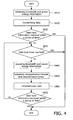
- FIG. 4 it is method flow chart of optimizing the wireless sensor network in accordance with an embodiment of present invention.
- step S410 the data transmission parameters of respective sensor nodes in the sensor network are initialized.
- convergent node broadcasts connection signaling actively, and after a data frame and a MAC (Media Access Control) command frame are successful received and verified at a sensor node, an acknowledge frame is returned to the convergent node.
- the sensor node is brought into a sleep operation mode.
- the convergent node and the sensor node are master-slave exchanged, and the convergent node module is brought into a mode operation status, and waiting for a response for connecting request signaling; and the sensor node is operated in the master mode, and waiting for wake-up when required or launches a connecting request in other ways.
- two initialized data transmission parameters can be obtained: a retransmission timeout and a retransmission times.
- the sensor node starts to transmit the data to another sensor node.
- step S430 it is to determine whether an acknowledge information about a successful data transmission fed-back from another sensor node is received in an initialized retransmission timeout. If an acknowledge information is received in the retransmission timeout, the whole process will end immediately.
- step S435 it is to determine that whether the total trial times of data retransmission (i.e. the initialized retransmission times or adjusted retransmission times) have been reached. If the total trial times of data retransmission have been reached, the whole process will end immediately.
- the total trial times of data retransmission i.e. the initialized retransmission times or adjusted retransmission times
- the sensor node If it is determined that the total trial times of data retransmission have not been reached, at step S440, the sensor node firstly acquires its current energy status information, and may acquires current available bandwidth information in the sensor network.
- the retransmission timeout and retransmission times are adjusted accordingly.
- the more sufficient power supply the sensor node has the shorter timeout is retransmitting the data to the objective sensor node adjusted to, and otherwise, the longer timeout is retransmitting the data adjusted to. In this way, the power consumption of the sensor node could be saved.
- the more sufficient power supply the sensor node has the more times are retransmitting the data to the objective sensor node adjusted to, and otherwise, the less times are retransmitting the data adjusted to. In this way, the power consumption of the sensor node could be saved.
- the shorter timeout is retransmitting the data to the objective sensor node adjusted to, and otherwise, the longer timeout is retransmitting the data adjusted to.
- the specific adjustment is shown in the figure 5 .
- step S460 according to the adjusted data transmission parameters, i.e. retransmission timeout and retransmission times, the data is retransmitted.
- step S470 it is to determine whether an acknowledge information about a successful data transmission fed-back from another sensor node is received in the adjusted retransmission timeout. If an acknowledge information is received in the initialized timeout, the whole process will end immediately. Otherwise, jump to step S440, its current energy status information is acquired again, and current available bandwidth information in the sensor network is acquired, and according to the energy status information and current available bandwidth information, the retransmission timeout and retransmission times are adjusted, until the data transmission is successful, or the retransmission times have been reached then the transmission is given up.
- the frequency of adjusting the data transmission data might be adjusted according to the actual network status. For example, it is to adjust once after three times of data transmission failure, or to adjust once in every certain period, such as 30 minutes.
- Figure 5 is an illustrative view of method of controlling energy expanding of sensor network nodes in accordance with an embodiment of present invention.
- T is indicative of interval between two data transmissions of a sensor node
- t1, t2 and t3 are indicative of the time in which the sensor node transmits a data for many times respectively
- b is indicative of the network available bandwidth
- bH, bM and bL are indicative of a higher available bandwidth, a middle available bandwidth and a lower available bandwidth respectively
- pS is indicative of the power supply status of the sensor node, for example, the power status of a node may be classified into three levels, i.e. high, middle, and low, which are expressed by the power information 1, 2, and 3 respectively.
- n is an adjust coefficient, for example, n may be set to equal to 20-30 according to the actual power supply status of the sensor node.
- the sensor node retransmits the same data to an objective sensor node, at the same time, according to the updated information, it is known that the current available bandwidth is bM, and the power supply status of the sensor node is p2, and then the retransmission timeout is adjusted to: T/(n*bM*p2).
- the sensor node does not receive an acknowledge information about a successful data receipt from the objective sensor node, go to stage 3, and the data is retransmitted to the objective sensor node.
- the sensor node retransmits the same data to an objective sensor node again, at the same time, according to the updated information, it is known that the current available bandwidth is bL, and the power supply status of the sensor node is p3, and then the retransmission timeout is adjusted to: T/(n*bL*p3).
- the sensor node does not receive an acknowledge information about a successful data receipt from the objective sensor node, the data is continued to be retransmitted to the objective sensor node, until the data transmission is successful, or retransmission times have been reached then the transmission is given up.
- the times at which the data is retransmitted to the objective sensor node can be adjusted accordingly based on the power supply status of the sensor node.
Description
- This invention is related to a wireless sensor network, in particular, to a method, apparatus and computer program product for controlling energy expanding of wireless sensor network nodes and to a sensor network.
- There are some limitations to the sensor network. Firstly, the communication capacity of sensor network is very limited; the communication bandwidth of sensors in sensor network is narrow and often varied, and the coverage range of communication is only several tens meters to hundreds meters. If the data transmission exceeds the available bandwidth, a high lost-packet rate will be caused.
- Secondly, the power energy of sensors is very limited; a lot of energy is required in the information sensing of sensor network, data process and communication, and if the node power supply of sensor network under Batteries-Supply can not be replaced, the energy consumption it caused will directly affect the lifecycle of whole sensor network.
- Cluster head data fusion is means of reducing node energy consumption by reducing network traffic. In accordance with this means, sensor network usually includes a plurality of node cluster, and each node cluster includes a central node, and a sensor network is divided into a plurality of sensor sub network, so it can avoid that data communication bottleneck of transferring original data directly from each sensor node to sensor network base station.
- Furthermore, the operation mode based on wake-up when required between coverage node (i.e. cluster head node) and sensor node in Zigbee network can also partly solve the problem of energy supply in the sensor network.
- However, a plurality of sensor nodes is included in the sensor network, and data process and communication status of each sensor node is different each other, the corresponding energy consumption status is different each other.
- International Application
WO2005091576 discloses a radio communication device and method of route searching. The radio communication device determines whether a message is destined for itself and subsequently determines a delay amount for responding or a relaying a transmission when the message is not addressed to itself. In a particular implementation the radio communication device monitors the remaining battery power, so as to enable the selection of a route through radio communication devices having more remaining battery power. - Therefore, on the premise that the communication capacity and power energy of sensor nodes are limited in a wireless sensor network, the problems of how to efficiently utilize the network resource to save the power consumption of sensor node and prolong the whole life of sensor network still need to be solved.
- Present invention is to provide a method and apparatus for controlling energy expanding of sensor network nodes, which are capable of efficiently utilize the network resource to save the power consumption of sensor node, and prolong the whole life of sensor network.
- In accordance with the present invention a method for controlling energy expanding of a sensor network is provided according to claim 1.
- In accordance with the present invention an apparatus for controlling energy expanding of a sensor network is provided according to claim 7.
- In accordance with the present invention a product of computer program for controlling energy expanding of a sensor network is provided according to claim 10.
- In accordance with the present invention a sensor network is provided according to claim 11.
- In summary, on the premise that the communication capacity and power energy of sensor nodes are limited in a wireless sensor network, the apparatus and method of present invention can adjust data transmission parameter of the nodes accordingly based on the energy information of the nodes, save the power consumption of sensor node, and prolong the life of sensor network, in order to more efficiently utilize the network resource.
- In the following, other objects and achievements of present invention will be apparent through the description of present invention and claims with reference to the figures, and prevent invention will be fully understood.
-
-
Figure 1 is an illustrative view of a sensor network configuration in accordance with an embodiment of present invention. -
Figure 2 is an illustrative view of a sensor network configuration in accordance with another embodiment of present invention. -
Figure 3 is an illustrative view of functional configuration of network controller in a sensor network in accordance with an embodiment of present invention. -
Figure 4 is method flow chart of controlling energy expanding of sensor network nodes in accordance with an embodiment of present invention. -
Figure 5 is an illustrative view of method of controlling energy expanding of sensor network nodes in accordance with an embodiment of present invention. - In all of above figures, same references denote the same, similar or corresponding characters or functions.
- In the following, the preferred embodiments of present invention will be described in details with reference to the accompany figures.
- In accordance with one embodiment of present invention, present invention will be described in details with respect to a method and apparatus for controlling energy expanding of sensor nodes in a wireless sensor network. It will be understood by those skilled in the art that present invention could be modified and applied in other types of network, such as Bluetooth network or Wireless Local Area Network (WLAN), on the basis of without departing the scope of content of present invention.
- In a wireless sensor network, in order to ensure a successful data transmission, a node transmits data to a receiving node, and the receiving node will send back feedback information after successful receives the data, so as to acknowledge the successful data transmission. If the node that sends data does not receive any feedback information about successful data transmission in a retransmission timeout, the data will be re-sent. If the node that sends data does still not receive any feedback information about successful data transmission after re-sending, the data will be re-sent for many times, until the data are transmitted successfully. Alternatively, if it is still not successful after a certain times of re-sending, the data transmission will be given up.
-
Figure 1 is an illustrative view of a sensor network configuration in accordance with an embodiment of present invention. This sensor network includes asensor network controller 110, a plurality ofwireless sensor nodes 120, and a plurality ofwired sensor nodes 130. - The
sensors sensor network controller 110 via wired or wireless connection, wherein thesensor network controller 110 being used to collect data, the function thereof being similar to a base station in a wireless communication network or a router in a wired communication network, or a combination of them. The wired communication between eachsensor sensor network controller 110 is via Local Area Network (LAN) or via dedicated communication line, and the wireless communication may adopt the Wireless Local Area Network (WLAN) or Bluetooth standard. - The
respective sensor nodes sensor network controller 110, for example, the wired transmission shown in solid line in the figures. At the same time, thesensor network controller 110 may also send the control signals to therespective sensors Fig. 1 that thesensor network controller 110 is a convergent point of all the detected data, and to analysis and process the detected data, and then educe a process center of the detected results, which is also a control center of optimizing the network. -
Figure 2 is an illustrative view of a sensor network configuration in accordance with another embodiment of present invention. In this embodiment, a plurality ofsensors data collector 210 via wired or wireless connection, constituting asensor network 220.Distinct sensor networks sensor network controller 250 via their respective data collectors. Thesensor network controller 250 collects sensor data from therespective sensor networks respective sensor networks respective sensors networks - As shown in
figure 3 , it is an illustrative view of functional configuration of network controller in a sensor network in accordance with an embodiment of present invention. - The
sensor network controller 300 includes an acquiringdevice 310 that includes an energyinformation acquiring device 314, and a adjustingdevice 320, wherein the energyinformation acquiring device 314 is used to acquire energy information, the energy information being indicative of the energy status of one node in the network. For example, the energy information may be indicative of the power supply status of a sensor node, for instance, the power status of a node may be classified into three levels, i.e. high, middle, and low, which are expressed by the values of 3, 2, and 1 respectively. - The energy information is monitored by the power monitor device (not shown in the figures) on the nodes in the network, and then transferred to the energy
information acquiring device 314. - The adjusting
device 320 is used to adjust at least one data transmission parameter of the node accordingly based on the energy information. Wherein the data transmission parameter may be the retransmission timeout and/or retransmission times, the retransmission timeout being the timeout in which the node that sends data will resend the data if it does not receive any feedback information about successful data transmission; the retransmission times being times at which the node that sends data will resend the data if it does not receive any feedback information about successful data transmission. - In accordance with an embodiment of present invention, the
sensor network controller 300 may further include an availablebandwidth acquiring device 312, for acquiring the status of available bandwidth when a node is transmitting data. The status of available bandwidth may be monitored by the network monitor device (not shown in the figures), and then transferred to the availablebandwidth acquiring device 312. - The adjusting
device 320 includes atimeout adjusting device 322, for adjusting the retransmission timeout of a sensor node based on the energy information acquired by the acquiring device. The more sufficient power supply the sensor node has, the shorter timeout is retransmitting the data to the objective sensor node adjusted to, and otherwise, the longer timeout is retransmitting the data adjusted to. In this way, the power consumption of the sensor node could be saved. - The adjusting
device 320 includes a retransmissiontimes adjusting device 324, for adjusting the times of retransmitting data after the data transmission failed, based on the energy information acquired by the acquiring device. The more sufficient power supply the sensor node has, the more times are retransmitting the data to the objective sensor node adjusted to, and otherwise, the less times are retransmitting the data adjusted to. In this way, the power consumption of the sensor node could be saved. - The
sensor network controller 300 further includes atransmission device 330, for the sensor nodes to send and receive data, and communicate with other sensor nodes in the sensor network. For example, thetransmission device 330 may be a signal transmitter/receiver under the protocol of Zigbee/Bluetooth network. - In present embodiment, acquiring the power of the
network controller 300 can be achieved by bandwidth acquiring, and the functions of adjusting the retransmission timeout and adjusting the retransmission times can be performed by various nodes in a sensor network, as long as these various nodes can communicate each other. - It should be understood that the all/part of functions of the
sensor network controller 300 disclosed inFig. 3 according to an embodiment of present invention, can also be achieved by appropriately programmed computer, the computer being loaded with a computer program for controlling energy expanding of sensor network nodes. The computer program includes: code for acquiring energy information, said energy information being indicative of the energy status of a node in the network, and; code for adjusting at least one data transmission parameter accordingly based on the energy information. - Above such a computer program can be stored in a storage media.
- These parts of above computer program code can be provided to a processor to generate a machine, so that the code executed on the processor creates a device that can achieve above functions.
- As shown in
Figure 4 , it is method flow chart of optimizing the wireless sensor network in accordance with an embodiment of present invention. - At first, at step S410, the data transmission parameters of respective sensor nodes in the sensor network are initialized. During the initializing communication process, convergent node broadcasts connection signaling actively, and after a data frame and a MAC (Media Access Control) command frame are successful received and verified at a sensor node, an acknowledge frame is returned to the convergent node. Next, the sensor node is brought into a sleep operation mode. Next, the convergent node and the sensor node are master-slave exchanged, and the convergent node module is brought into a mode operation status, and waiting for a response for connecting request signaling; and the sensor node is operated in the master mode, and waiting for wake-up when required or launches a connecting request in other ways.
- After initialization, two initialized data transmission parameters can be obtained: a retransmission timeout and a retransmission times.
- At step S420, the sensor node starts to transmit the data to another sensor node.
- At step S430, it is to determine whether an acknowledge information about a successful data transmission fed-back from another sensor node is received in an initialized retransmission timeout. If an acknowledge information is received in the retransmission timeout, the whole process will end immediately.
- If an acknowledge information is not received by the sensor node in the initialized timeout, at step S435, it is to determine that whether the total trial times of data retransmission (i.e. the initialized retransmission times or adjusted retransmission times) have been reached. If the total trial times of data retransmission have been reached, the whole process will end immediately.
- If it is determined that the total trial times of data retransmission have not been reached, at step S440, the sensor node firstly acquires its current energy status information, and may acquires current available bandwidth information in the sensor network.
- At step S450, according to the acquired energy status information and/or current available bandwidth information, the retransmission timeout and retransmission times are adjusted accordingly.
- The more sufficient power supply the sensor node has, the shorter timeout is retransmitting the data to the objective sensor node adjusted to, and otherwise, the longer timeout is retransmitting the data adjusted to. In this way, the power consumption of the sensor node could be saved. The more sufficient power supply the sensor node has, the more times are retransmitting the data to the objective sensor node adjusted to, and otherwise, the less times are retransmitting the data adjusted to. In this way, the power consumption of the sensor node could be saved.
- For the same reason, the more sufficient available bandwidth the sensor node has, the shorter timeout is retransmitting the data to the objective sensor node adjusted to, and otherwise, the longer timeout is retransmitting the data adjusted to. The specific adjustment is shown in the
figure 5 . - At step S460, according to the adjusted data transmission parameters, i.e. retransmission timeout and retransmission times, the data is retransmitted.
- At step S470, it is to determine whether an acknowledge information about a successful data transmission fed-back from another sensor node is received in the adjusted retransmission timeout. If an acknowledge information is received in the initialized timeout, the whole process will end immediately. Otherwise, jump to step S440, its current energy status information is acquired again, and current available bandwidth information in the sensor network is acquired, and according to the energy status information and current available bandwidth information, the retransmission timeout and retransmission times are adjusted, until the data transmission is successful, or the retransmission times have been reached then the transmission is given up.
- It could be understood that the frequency of adjusting the data transmission data (step S450) might be adjusted according to the actual network status. For example, it is to adjust once after three times of data transmission failure, or to adjust once in every certain period, such as 30 minutes.
-
Figure 5 is an illustrative view of method of controlling energy expanding of sensor network nodes in accordance with an embodiment of present invention. - As shown in the figure, wherein T is indicative of interval between two data transmissions of a sensor node; t1, t2 and t3 are indicative of the time in which the sensor node transmits a data for many times respectively; b is indicative of the network available bandwidth, and bH, bM and bL are indicative of a higher available bandwidth, a middle available bandwidth and a lower available bandwidth respectively; pS is indicative of the power supply status of the sensor node, for example, the power status of a node may be classified into three levels, i.e. high, middle, and low, which are expressed by the power information 1, 2, and 3 respectively.
- Firstly, at stage 1, during the period t1, the sensor node transmits a data to an objective sensor node, and the current available bandwidth is bH, and the power supply status of the sensor node is p1, then if during the period T/(n*bH*p1) the sensor node does not receive an acknowledge information about a successful data receipt from the objective sensor node, go to stage 2, and the data is retransmitted to the objective sensor node. Wherein n is an adjust coefficient, for example, n may be set to equal to 20-30 according to the actual power supply status of the sensor node.
- Next, at stage 2, during the period t2, the sensor node retransmits the same data to an objective sensor node, at the same time, according to the updated information, it is known that the current available bandwidth is bM, and the power supply status of the sensor node is p2, and then the retransmission timeout is adjusted to: T/(n*bM*p2).
- According to the adjusted timeout, if at the time t1+t2+T/(n*bH*p1)+ T/(n*bM*p2), the sensor node does not receive an acknowledge information about a successful data receipt from the objective sensor node, go to stage 3, and the data is retransmitted to the objective sensor node.
- Next, at stage 3, during the period t3, the sensor node retransmits the same data to an objective sensor node again, at the same time, according to the updated information, it is known that the current available bandwidth is bL, and the power supply status of the sensor node is p3, and then the retransmission timeout is adjusted to: T/(n*bL*p3).
- According to the adjusted timeout, if at the time t1+t2+t3+T/(n=*bH*p1)+ T/(n*bM*p2)+ T/(n*bL*p3), the sensor node does not receive an acknowledge information about a successful data receipt from the objective sensor node, the data is continued to be retransmitted to the objective sensor node, until the data transmission is successful, or retransmission times have been reached then the transmission is given up.
- According to an embodiment of present invention, the times at which the data is retransmitted to the objective sensor node can be adjusted accordingly based on the power supply status of the sensor node. The more sufficient power supply the sensor node has, the more is the total trial times to retransmit the data to the objective sensor node adjusted, and otherwise, the less is the (total trial) times to retransmit the data adjusted. In this way, the power consumption of the sensor node could be saved.
- For example, the power status pS of a sensor node may be classified into three levels, i.e. high, middle, and low, which are expressed by the value 1, 2, and 3 respectively, and then the total trial times to retransmit the data R could be calculated from R=m/pS. Wherein m is a positive integer coefficient, for example, it can be set to m=8, and then if the power status of the sensor node pS=2, the times to retransmit the data R equals to 4 times.
- It should be understood by those skilled in the art that, the method and apparatus disclosed in present invention can be modified without departing the content of present invention. Therefore, the protect scope of present invention should be limited by the content of appended claims.
Claims (11)
- A method for controlling energy expanding of a sensor network (220, 230, 240), comprising steps of:(a) acquiring an energy information (S440), said energy information being indicative of an energy status of a node (120,130) in the network (220, 230, 240),(b) acquiring a bandwidth information (S440), said bandwidth information being indicative of the available bandwidth status of the node (120, 130) and;(c) adjusting (S450) at least one data transmission parameter of the node (120, 130) accordingly based on the energy information and based on the bandwidth information, the data transmission parameter being for controlling retransmission if the node (120, 130) does not receive any feedback information about successful data transmission.
- The method as claimed in claim 1, wherein said data transmission parameter is the retransmission timeout after which said node (120, 130) starts to retransmit the data after the data transmission fails.
- The method as claimed in claim 2, wherein
energy information indicating a higher power reserve results in a shorter retransmission timeout period and
energy information indicating a lower power reserve results in a longer retransmission timeout period. - The method as claimed in claim 2, wherein- bandwidth information indicating more available bandwidth results in a shorter retransmission timeout period and- bandwidth information indicating less available bandwidth results in a longer retransmission timeout period.
- The method as claimed in claim 1, wherein said data transmission parameter is the retransmission times which is the number of times said node (120, 130) starts to retransmit the data after the data transmission fails.
- The method as claimed in claim 5, wherein- energy information indicating a higher power reserve results in a higher number of times at which said node (120, 130) starts to retransmit and- energy information indicating a lower power reserve results in a lower number of times at which said node (120, 130) starts to retransmit.
- An apparatus (300) for controlling energy expanding of a sensor network (220, 230, 240), comprising:a first acquiring means (314) for acquiring energy information, said energy information being indicative of an energy status of a node (120,130) in the network (220, 230, 240),a second acquiring means (312) for acquiring a bandwidth information, said bandwidth information indicative of the available bandwidth status of the node (120, 130) and;an adjusting device (320) for adjusting at least one data transmission parameter of the node (120, 130) accordingly based on the energy information and based on the bandwidth information, the data transmission parameter being for controlling retransmission if the node (120, 130) does not receive any feedback information about successful data transmission.
- The apparatus (300) as claimed in claim 7, wherein said data transmission parameter is the retransmission timeout after which said node (120, 130) starts to retransmit the data after the data transmission fails.
- The apparatus (300) as claimed in claim 7, wherein said data transmission parameter is the retransmission times which is the number of times said node (120,130) starts to retransmit the data after the data transmission fails.
- A product of computer program for controlling energy expanding of a sensor network (220, 230, 240), comprising:code for acquiring an energy information, said energy information being indicative of the energy status of a node (120, 130) in the network (220, 230, 240),code for acquiring a bandwidth information, said bandwidth information being indicative of the available bandwidth status of the node (120, 130) and;code for adjusting at least one data transmission parameter of the node (120, 130) accordingly based on the energy information and based on the bandwidth information, the data transmission parameter being for controlling retransmission if the node (120, 130) does not receive any feedback information about successful data transmission.
- A sensor network (220, 230, 240), comprising:a plurality of nodes (120,130); anda network controller (300) connected with said plurality of nodes (120, 130);wherein said network controller (300) comprising:a first acquiring device (314) for acquiring an energy information, said energy information being indicative of an energy status of a node (120, 130) in the network (220, 230, 240);a second acquiring device (312) for acquiring a bandwidth information, said bandwidth information being indicative of the available bandwidth status of the node (120, 130); andan adjusting device (320), for adjusting at least one data transmission parameter of the node (120, 130) accordingly based on the energy information and based on the bandwidth information, the data transmission parameter being for controlling retransmission if the node (120, 130) does not receive any feedback information about successful data transmission.
Applications Claiming Priority (2)
| Application Number | Priority Date | Filing Date | Title |
|---|---|---|---|
| CN200610077346 | 2006-04-29 | ||
| PCT/IB2007/051418 WO2007125462A2 (en) | 2006-04-29 | 2007-04-19 | Method and apparatus for controlling energy consumption of sensor network nodes |
Publications (2)
| Publication Number | Publication Date |
|---|---|
| EP2025110A2 EP2025110A2 (en) | 2009-02-18 |
| EP2025110B1 true EP2025110B1 (en) | 2015-03-25 |
Family
ID=38655892
Family Applications (1)
| Application Number | Title | Priority Date | Filing Date |
|---|---|---|---|
| EP07735554.3A Active EP2025110B1 (en) | 2006-04-29 | 2007-04-19 | Method and apparatus for controlling energy consumption of sensor network nodes |
Country Status (5)
| Country | Link |
|---|---|
| US (1) | US9614648B2 (en) |
| EP (1) | EP2025110B1 (en) |
| JP (1) | JP5038399B2 (en) |
| CN (1) | CN101449525B (en) |
| WO (1) | WO2007125462A2 (en) |
Families Citing this family (53)
| Publication number | Priority date | Publication date | Assignee | Title |
|---|---|---|---|---|
| ES2396309T3 (en) | 2005-12-14 | 2013-02-20 | Research In Motion Limited | Method and apparatus for radio resource control aimed at a user equipment |
| US8265034B2 (en) | 2006-05-17 | 2012-09-11 | Research In Motion Limited | Method and system for a signaling connection release indication |
| ES2353609T3 (en) | 2006-05-17 | 2011-03-03 | Research In Motion Limited | METHOD AND SYSTEM FOR INDICATION OF SIGNALING CONNECTION RELEASE IN A UMTS NETWORK. |
| JP2008078963A (en) * | 2006-09-21 | 2008-04-03 | Univ Waseda | Communication method for wireless sensor network, and sensor node |
| US8648734B2 (en) * | 2007-09-13 | 2014-02-11 | University Of Louisville Research Foundation, Inc. | System and method for collecting data using wired sensors connected to wireless nodes |
| ATE553628T1 (en) | 2007-11-13 | 2012-04-15 | Research In Motion Ltd | METHOD AND APPARATUS FOR STATUS/MODE TRANSITIONS |
| US8634325B2 (en) * | 2007-12-31 | 2014-01-21 | Schneide Electric USA, Inc. | Tuning of industrial automation system performance based on device operating characteristics |
| CN102210190B (en) | 2008-11-10 | 2015-05-06 | 黑莓有限公司 | Method and apparatus of selecting if it is transmitted that the indication information of asking for more energy-saving state or mode aiming at bearing model |
| KR101127598B1 (en) * | 2008-12-10 | 2012-03-23 | 한국전자통신연구원 | Sink node for multiple radio interface and DMA-based data transfer method in wireless sensor node |
| CN104125630B (en) * | 2009-04-13 | 2018-03-09 | 华为技术有限公司 | Method, equipment and the system of regulating power consumption |
| CN101860948B (en) | 2009-04-13 | 2014-07-30 | 华为技术有限公司 | Method, equipment and system for regulating power consumption |
| EP2285033B1 (en) * | 2009-08-13 | 2012-10-03 | Alcatel Lucent | Modification of data transmission regime |
| CN101631361B (en) * | 2009-08-13 | 2011-08-31 | 上海交通大学 | Method for optimizing network lifetime of wireless LAN |
| CN102783242A (en) | 2009-11-23 | 2012-11-14 | 捷讯研究有限公司 | State or mode transition triggering based on SRI message transmission |
| CA2781630C (en) | 2009-11-23 | 2019-05-21 | Research In Motion Limited | Method and apparatus for state/mode transitioning |
| EP2505036B1 (en) | 2009-11-23 | 2018-08-22 | BlackBerry Limited | Method and apparatus for state/mode transitioning |
| US8983532B2 (en) | 2009-12-30 | 2015-03-17 | Blackberry Limited | Method and system for a wireless communication device to adopt varied functionalities based on different communication systems by specific protocol messages |
| US8457803B2 (en) | 2010-02-10 | 2013-06-04 | Enernoc, Inc. | Apparatus and method for demand coordination network |
| KR101038097B1 (en) * | 2010-03-31 | 2011-06-01 | 전자부품연구원 | Magnetic field communication method for recognizing multi-node |
| CN101873349B (en) * | 2010-06-08 | 2016-03-09 | 武汉理工大学 | The multinode real-time power consumption monitoring system in the environment of wireless sensor network |
| US8509923B2 (en) * | 2010-06-30 | 2013-08-13 | Motorola Solutions, Inc. | Methods for managing power consumption in a sensor network |
| DE102010033756A1 (en) | 2010-08-09 | 2012-02-09 | Siemens Aktiengesellschaft | A method for computer-aided control of the electrical energy consumption of a plurality of energy consumers in an electrical energy network |
| WO2012027844A1 (en) | 2010-08-30 | 2012-03-08 | Socovar S.E.C. | Energy consumption evaluation system having reduced energy consumption |
| CN101951414B (en) * | 2010-10-22 | 2012-10-10 | 无锡市云感科技股份有限公司 | Information system of wireless sensing network combined with internet of things platform |
| KR101171147B1 (en) * | 2010-12-29 | 2012-08-06 | 전자부품연구원 | Sensor node and control method thereof |
| JP5525467B2 (en) * | 2011-02-18 | 2014-06-18 | 株式会社日立製作所 | Sensor device and control method thereof |
| CN102695249B (en) * | 2011-03-23 | 2014-10-08 | 北京天地互连信息技术有限公司 | Energy saving method for IPv6 wireless sensor network |
| CN102186184B (en) * | 2011-06-03 | 2013-11-06 | 大连理工大学 | Energy consumption calculation method of ZigBee wireless network node |
| US9049078B2 (en) * | 2011-08-31 | 2015-06-02 | Eneroc, Inc. | NOC-oriented control of a demand coordination network |
| US9082294B2 (en) | 2011-09-14 | 2015-07-14 | Enernoc, Inc. | Apparatus and method for receiving and transporting real time energy data |
| EP2777358B1 (en) | 2011-11-11 | 2018-01-10 | BlackBerry Limited | Method and apparatus for user equipment state transition |
| US9921597B2 (en) * | 2011-12-09 | 2018-03-20 | Kyocera Corporation | Power control apparatus, power control system, and control method |
| JP6159346B2 (en) * | 2012-02-17 | 2017-07-05 | ユニバーシティ オブ ヴァージニア パテント ファウンデーション | Energy harvesting and sensor node control |
| KR101303901B1 (en) * | 2012-03-26 | 2013-09-05 | 이화여자대학교 산학협력단 | Method for generating cooperative relay path in wireless sensor networks |
| US9191442B2 (en) * | 2012-04-03 | 2015-11-17 | Accenture Global Services Limited | Adaptive sensor data selection and sampling based on current and future context |
| CN103685011B (en) | 2012-09-14 | 2017-03-15 | 华为技术有限公司 | A kind of method and apparatus for determining energy-efficient routing |
| US9816370B2 (en) * | 2012-09-19 | 2017-11-14 | Honeywell International Inc. | System and method for optimizing an operation of a sensor used with wellbore equipment |
| CN102946298B (en) * | 2012-11-23 | 2015-08-19 | 电子科技大学 | Based on the data repeating method of opportunistic network coding in wireless sensor network |
| CN103124427A (en) * | 2012-12-23 | 2013-05-29 | 无锡泛联软件科技有限公司 | Backbone structure constructing method of wireless sensor network based on communication supporting tree |
| JP6051939B2 (en) * | 2013-02-27 | 2016-12-27 | 富士ゼロックス株式会社 | Bandwidth measuring device and program |
| CN103297983B (en) * | 2013-05-06 | 2015-11-25 | 南京邮电大学 | A kind of wireless sensor network node dynamic deployment method of stream Network Based |
| EP3158623B1 (en) * | 2014-08-14 | 2020-02-26 | Siemens Aktiengesellschaft | Method and system for monitoring the operating state of an energy supply network |
| CN104683466B (en) * | 2015-03-03 | 2018-01-09 | 友达光电股份有限公司 | Server and its operation method |
| US9904269B2 (en) | 2015-03-31 | 2018-02-27 | Enernoc, Inc. | Apparatus and method for demand coordination network control |
| CN104812034A (en) * | 2015-04-27 | 2015-07-29 | 深圳市民展科技开发有限公司 | Processor energy saving method and system for reduction of power consumption |
| US10540690B2 (en) | 2016-05-03 | 2020-01-21 | Enel X North America, Inc. | Apparatus and method for focused marketing messaging based on estimated building occupancy |
| US10324435B2 (en) | 2016-05-03 | 2019-06-18 | Enel X North America, Inc. | Apparatus and method for occupancy based demand response dispatch prioritization |
| US10552869B2 (en) | 2016-05-03 | 2020-02-04 | Enel X North America, Inc. | Apparatus and method for targeted marketing based on estimated building occupancy |
| US10203712B2 (en) * | 2016-05-03 | 2019-02-12 | Enel X North America, Inc. | Apparatus and method for energy management based on estimated resource utilization |
| US10203673B2 (en) * | 2016-05-03 | 2019-02-12 | Enel X North America, Inc. | Apparatus and method for occupancy based energy consumption management |
| US10222771B2 (en) | 2016-05-03 | 2019-03-05 | Enel X North America, Inc. | Apparatus and method for traffic control based on estimated building occupancy |
| US10488878B2 (en) | 2016-05-03 | 2019-11-26 | Enel X North America, Inc. | Apparatus and method for energy management of multiple facilities as a function of estimated occupancy |
| CN109451529A (en) * | 2019-01-02 | 2019-03-08 | 成都华日通讯技术有限公司 | A kind of miniature spectral sensor net system and its synergistic data processing method |
Family Cites Families (22)
| Publication number | Priority date | Publication date | Assignee | Title |
|---|---|---|---|---|
| JPH089462A (en) | 1994-06-20 | 1996-01-12 | Toshiba Corp | Asap message communication system |
| US5974327A (en) * | 1997-10-21 | 1999-10-26 | At&T Corp. | Adaptive frequency channel assignment based on battery power level in wireless access protocols |
| USH1880H (en) * | 1998-09-25 | 2000-10-03 | Dsc/Celcore, Inc. | System and method for processing wireless voice and data telecommunications |
| JP3430509B2 (en) | 1999-12-03 | 2003-07-28 | 日本電気株式会社 | Data communication system and method |
| JP4116212B2 (en) * | 1999-12-28 | 2008-07-09 | 株式会社東芝 | COMMUNICATION DEVICE AND ITS CONTROL METHOD |
| US6760303B1 (en) * | 2000-03-29 | 2004-07-06 | Telefonaktiebolaget Lm Ericsson (Publ) | Channel-type switching based on cell load |
| JP3585823B2 (en) * | 2000-09-29 | 2004-11-04 | 株式会社東芝 | Wireless communication system and timeout value updating method thereof |
| US6747993B2 (en) * | 2001-02-01 | 2004-06-08 | Motorola, Inc. | Method and apparatus for adjusting a communication timer in a communication network |
| US7027843B2 (en) * | 2002-03-21 | 2006-04-11 | Lenovo (Singapore) Pte. Ltd. | Wireless device power optimization |
| US6996763B2 (en) * | 2003-01-10 | 2006-02-07 | Qualcomm Incorporated | Operation of a forward link acknowledgement channel for the reverse link data |
| JP4214793B2 (en) * | 2003-02-19 | 2009-01-28 | 日本電気株式会社 | Wireless communication system, server, base station, mobile terminal, and retransmission timeout time determination method used for them |
| US7636132B2 (en) * | 2003-04-17 | 2009-12-22 | Sharp Kabushiki Kaisha | Transmitter, receiver, wireless system, control method, control program, and computer-readable recording medium containing the program |
| KR100771715B1 (en) * | 2003-09-02 | 2007-10-30 | 엘지전자 주식회사 | Apparatus and method for controlling data communication for wireless LAN |
| US7227847B2 (en) * | 2004-03-11 | 2007-06-05 | Ixi Mobile (R&D) Ltd. | Power management system and method for a wireless communications device |
| JP4569328B2 (en) * | 2004-03-18 | 2010-10-27 | パナソニック株式会社 | Wireless communication apparatus and route search method |
| EP1596616A1 (en) * | 2004-05-14 | 2005-11-16 | Research In Motion Limited | Method and apparatus for expeditiously releasing network resources for a mobile station based on low battery and lost signal conditions |
| CN1753515A (en) * | 2004-09-20 | 2006-03-29 | 北京三星通信技术研究有限公司 | The method of transmitting coding efficiency appointment that is used for the power dispatching of base stations control |
| US20060268787A1 (en) * | 2005-05-24 | 2006-11-30 | Meshnetworks, Inc. | Method and system for controlling the transmission power of at least one node in a wireless network |
| US7843831B2 (en) * | 2006-08-22 | 2010-11-30 | Embarq Holdings Company Llc | System and method for routing data on a packet network |
| US8195097B2 (en) * | 2006-09-08 | 2012-06-05 | Qualcomm Incorporated | Serving sector interference broadcast and corresponding RL traffic power control |
| US7764965B2 (en) * | 2007-04-10 | 2010-07-27 | Microsoft Corporation | Dynamically changing service characteristics based on device and network connectivity attributes |
| US9295000B2 (en) * | 2007-04-25 | 2016-03-22 | Kyocera Corporation | Power management in a portable communication device configuration version |
-
2007
- 2007-04-19 US US12/298,595 patent/US9614648B2/en active Active
- 2007-04-19 EP EP07735554.3A patent/EP2025110B1/en active Active
- 2007-04-19 JP JP2009507221A patent/JP5038399B2/en active Active
- 2007-04-19 WO PCT/IB2007/051418 patent/WO2007125462A2/en active Application Filing
- 2007-04-19 CN CN200780015577.8A patent/CN101449525B/en active Active
Also Published As
| Publication number | Publication date |
|---|---|
| WO2007125462A3 (en) | 2008-12-18 |
| US20090185542A1 (en) | 2009-07-23 |
| EP2025110A2 (en) | 2009-02-18 |
| JP2009535883A (en) | 2009-10-01 |
| CN101449525A (en) | 2009-06-03 |
| US9614648B2 (en) | 2017-04-04 |
| WO2007125462A2 (en) | 2007-11-08 |
| CN101449525B (en) | 2016-08-10 |
| JP5038399B2 (en) | 2012-10-03 |
Similar Documents
| Publication | Publication Date | Title |
|---|---|---|
| EP2025110B1 (en) | Method and apparatus for controlling energy consumption of sensor network nodes | |
| US8194571B2 (en) | Protocol for reliable, self-organizing, low-power wireless network for security and building automation systems | |
| EP3624303B1 (en) | A system and a method for charging multiple power receivers in a wireless charging environment | |
| EP1505848A2 (en) | Channel selection method, and wireless station and wireless terminal employing it | |
| JP5504322B2 (en) | Communication method, transmission and reception station, and related computer program | |
| US8837354B2 (en) | Apparatus and method for supporting wireless actuators and other devices in process control systems | |
| WO2006071289A1 (en) | Method and system for recovery from access point infrastructure link failures | |
| WO2014130191A1 (en) | Link verification in a wireless network | |
| JP2021090185A (en) | Data transmission method and communication system | |
| JP5438614B2 (en) | Network reconstruction method and network system | |
| EP3869739B1 (en) | Method for monitoring apparatus | |
| US7411933B2 (en) | Radio communication device, radio communication method, and computer program | |
| JP3971359B2 (en) | Wireless communication method, wireless communication terminal accommodating apparatus, and wireless communication terminal | |
| JP4977943B2 (en) | Communications system | |
| CN106878447B (en) | Data acquisition system based on ZigBee communication | |
| EP2702794B1 (en) | Managing behavior of release-7 and release-8 user equipment during continuous packet connectivity configuration | |
| JP7088022B2 (en) | Communication terminals, communication methods, programs and wireless systems | |
| CN114339938B (en) | System and method for optimizing transmission reliability of airborne wireless sensor network | |
| JP4300911B2 (en) | Wireless communication network system | |
| CN102802237A (en) | Data forwarding control method and wireless centralized control equipment | |
| US8995283B2 (en) | Managing behavior of Release-7 and Release-8 user equipment during continuous packet connectivity configuration | |
| JP4093049B2 (en) | Communication device | |
| WO2022268288A1 (en) | Wireless sensor and actuator system | |
| CN116803011A (en) | Communication protocol for implementing services in a wireless power transfer network | |
| JP2012231300A (en) | Wireless relay transmission system |
Legal Events
| Date | Code | Title | Description |
|---|---|---|---|
| PUAI | Public reference made under article 153(3) epc to a published international application that has entered the european phase |
Free format text: ORIGINAL CODE: 0009012 |
|
| AK | Designated contracting states |
Kind code of ref document: A2 Designated state(s): AT BE BG CH CY CZ DE DK EE ES FI FR GB GR HU IE IS IT LI LT LU LV MC MT NL PL PT RO SE SI SK TR |
|
| AX | Request for extension of the european patent |
Extension state: AL BA HR MK RS |
|
| 17P | Request for examination filed |
Effective date: 20090618 |
|
| RBV | Designated contracting states (corrected) |
Designated state(s): AT BE BG CH CY CZ DE DK EE ES FI FR GB GR HU IE IS IT LI LT LU LV MC MT NL PL PT RO SE SI SK TR |
|
| 17Q | First examination report despatched |
Effective date: 20090709 |
|
| DAX | Request for extension of the european patent (deleted) | ||
| RAP1 | Party data changed (applicant data changed or rights of an application transferred) |
Owner name: KONINKLIJKE PHILIPS N.V. |
|
| REG | Reference to a national code |
Ref country code: DE Ref legal event code: R079 Ref document number: 602007040775 Country of ref document: DE Free format text: PREVIOUS MAIN CLASS: H04L0012560000 Ipc: H04W0040100000 |
|
| GRAP | Despatch of communication of intention to grant a patent |
Free format text: ORIGINAL CODE: EPIDOSNIGR1 |
|
| RIC1 | Information provided on ipc code assigned before grant |
Ipc: H04W 40/24 20090101ALI20141014BHEP Ipc: H04W 84/18 20090101ALN20141014BHEP Ipc: H04W 40/10 20090101AFI20141014BHEP Ipc: H04W 52/02 20090101ALI20141014BHEP |
|
| INTG | Intention to grant announced |
Effective date: 20141029 |
|
| GRAS | Grant fee paid |
Free format text: ORIGINAL CODE: EPIDOSNIGR3 |
|
| GRAA | (expected) grant |
Free format text: ORIGINAL CODE: 0009210 |
|
| AK | Designated contracting states |
Kind code of ref document: B1 Designated state(s): AT BE BG CH CY CZ DE DK EE ES FI FR GB GR HU IE IS IT LI LT LU LV MC MT NL PL PT RO SE SI SK TR |
|
| REG | Reference to a national code |
Ref country code: GB Ref legal event code: FG4D |
|
| REG | Reference to a national code |
Ref country code: CH Ref legal event code: EP |
|
| REG | Reference to a national code |
Ref country code: IE Ref legal event code: FG4D |
|
| REG | Reference to a national code |
Ref country code: DE Ref legal event code: R096 Ref document number: 602007040775 Country of ref document: DE Effective date: 20150507 |
|
| REG | Reference to a national code |
Ref country code: AT Ref legal event code: REF Ref document number: 718489 Country of ref document: AT Kind code of ref document: T Effective date: 20150515 |
|
| PG25 | Lapsed in a contracting state [announced via postgrant information from national office to epo] |
Ref country code: LT Free format text: LAPSE BECAUSE OF FAILURE TO SUBMIT A TRANSLATION OF THE DESCRIPTION OR TO PAY THE FEE WITHIN THE PRESCRIBED TIME-LIMIT Effective date: 20150325 Ref country code: FI Free format text: LAPSE BECAUSE OF FAILURE TO SUBMIT A TRANSLATION OF THE DESCRIPTION OR TO PAY THE FEE WITHIN THE PRESCRIBED TIME-LIMIT Effective date: 20150325 Ref country code: SE Free format text: LAPSE BECAUSE OF FAILURE TO SUBMIT A TRANSLATION OF THE DESCRIPTION OR TO PAY THE FEE WITHIN THE PRESCRIBED TIME-LIMIT Effective date: 20150325 |
|
| REG | Reference to a national code |
Ref country code: AT Ref legal event code: MK05 Ref document number: 718489 Country of ref document: AT Kind code of ref document: T Effective date: 20150325 |
|
| REG | Reference to a national code |
Ref country code: LT Ref legal event code: MG4D |
|
| PG25 | Lapsed in a contracting state [announced via postgrant information from national office to epo] |
Ref country code: GR Free format text: LAPSE BECAUSE OF FAILURE TO SUBMIT A TRANSLATION OF THE DESCRIPTION OR TO PAY THE FEE WITHIN THE PRESCRIBED TIME-LIMIT Effective date: 20150626 Ref country code: LV Free format text: LAPSE BECAUSE OF FAILURE TO SUBMIT A TRANSLATION OF THE DESCRIPTION OR TO PAY THE FEE WITHIN THE PRESCRIBED TIME-LIMIT Effective date: 20150325 |
|
| PG25 | Lapsed in a contracting state [announced via postgrant information from national office to epo] |
Ref country code: NL Free format text: LAPSE BECAUSE OF FAILURE TO SUBMIT A TRANSLATION OF THE DESCRIPTION OR TO PAY THE FEE WITHIN THE PRESCRIBED TIME-LIMIT Effective date: 20150325 |
|
| PG25 | Lapsed in a contracting state [announced via postgrant information from national office to epo] |
Ref country code: PT Free format text: LAPSE BECAUSE OF FAILURE TO SUBMIT A TRANSLATION OF THE DESCRIPTION OR TO PAY THE FEE WITHIN THE PRESCRIBED TIME-LIMIT Effective date: 20150727 Ref country code: RO Free format text: LAPSE BECAUSE OF FAILURE TO SUBMIT A TRANSLATION OF THE DESCRIPTION OR TO PAY THE FEE WITHIN THE PRESCRIBED TIME-LIMIT Effective date: 20150325 Ref country code: SK Free format text: LAPSE BECAUSE OF FAILURE TO SUBMIT A TRANSLATION OF THE DESCRIPTION OR TO PAY THE FEE WITHIN THE PRESCRIBED TIME-LIMIT Effective date: 20150325 Ref country code: ES Free format text: LAPSE BECAUSE OF FAILURE TO SUBMIT A TRANSLATION OF THE DESCRIPTION OR TO PAY THE FEE WITHIN THE PRESCRIBED TIME-LIMIT Effective date: 20150325 Ref country code: CZ Free format text: LAPSE BECAUSE OF FAILURE TO SUBMIT A TRANSLATION OF THE DESCRIPTION OR TO PAY THE FEE WITHIN THE PRESCRIBED TIME-LIMIT Effective date: 20150325 Ref country code: EE Free format text: LAPSE BECAUSE OF FAILURE TO SUBMIT A TRANSLATION OF THE DESCRIPTION OR TO PAY THE FEE WITHIN THE PRESCRIBED TIME-LIMIT Effective date: 20150325 |
|
| PG25 | Lapsed in a contracting state [announced via postgrant information from national office to epo] |
Ref country code: MC Free format text: LAPSE BECAUSE OF FAILURE TO SUBMIT A TRANSLATION OF THE DESCRIPTION OR TO PAY THE FEE WITHIN THE PRESCRIBED TIME-LIMIT Effective date: 20150325 Ref country code: AT Free format text: LAPSE BECAUSE OF FAILURE TO SUBMIT A TRANSLATION OF THE DESCRIPTION OR TO PAY THE FEE WITHIN THE PRESCRIBED TIME-LIMIT Effective date: 20150325 Ref country code: IS Free format text: LAPSE BECAUSE OF FAILURE TO SUBMIT A TRANSLATION OF THE DESCRIPTION OR TO PAY THE FEE WITHIN THE PRESCRIBED TIME-LIMIT Effective date: 20150725 Ref country code: PL Free format text: LAPSE BECAUSE OF FAILURE TO SUBMIT A TRANSLATION OF THE DESCRIPTION OR TO PAY THE FEE WITHIN THE PRESCRIBED TIME-LIMIT Effective date: 20150325 |
|
| REG | Reference to a national code |
Ref country code: CH Ref legal event code: PL |
|
| REG | Reference to a national code |
Ref country code: DE Ref legal event code: R097 Ref document number: 602007040775 Country of ref document: DE |
|
| REG | Reference to a national code |
Ref country code: IE Ref legal event code: MM4A |
|
| PG25 | Lapsed in a contracting state [announced via postgrant information from national office to epo] |
Ref country code: IT Free format text: LAPSE BECAUSE OF FAILURE TO SUBMIT A TRANSLATION OF THE DESCRIPTION OR TO PAY THE FEE WITHIN THE PRESCRIBED TIME-LIMIT Effective date: 20150325 Ref country code: LI Free format text: LAPSE BECAUSE OF NON-PAYMENT OF DUE FEES Effective date: 20150430 Ref country code: DK Free format text: LAPSE BECAUSE OF FAILURE TO SUBMIT A TRANSLATION OF THE DESCRIPTION OR TO PAY THE FEE WITHIN THE PRESCRIBED TIME-LIMIT Effective date: 20150325 Ref country code: CH Free format text: LAPSE BECAUSE OF NON-PAYMENT OF DUE FEES Effective date: 20150430 |
|
| PLBE | No opposition filed within time limit |
Free format text: ORIGINAL CODE: 0009261 |
|
| STAA | Information on the status of an ep patent application or granted ep patent |
Free format text: STATUS: NO OPPOSITION FILED WITHIN TIME LIMIT |
|
| 26N | No opposition filed |
Effective date: 20160105 |
|
| REG | Reference to a national code |
Ref country code: FR Ref legal event code: PLFP Year of fee payment: 10 |
|
| PG25 | Lapsed in a contracting state [announced via postgrant information from national office to epo] |
Ref country code: IE Free format text: LAPSE BECAUSE OF NON-PAYMENT OF DUE FEES Effective date: 20150419 |
|
| PG25 | Lapsed in a contracting state [announced via postgrant information from national office to epo] |
Ref country code: SI Free format text: LAPSE BECAUSE OF FAILURE TO SUBMIT A TRANSLATION OF THE DESCRIPTION OR TO PAY THE FEE WITHIN THE PRESCRIBED TIME-LIMIT Effective date: 20150325 |
|
| PG25 | Lapsed in a contracting state [announced via postgrant information from national office to epo] |
Ref country code: BE Free format text: LAPSE BECAUSE OF FAILURE TO SUBMIT A TRANSLATION OF THE DESCRIPTION OR TO PAY THE FEE WITHIN THE PRESCRIBED TIME-LIMIT Effective date: 20150325 |
|
| REG | Reference to a national code |
Ref country code: GB Ref legal event code: 732E Free format text: REGISTERED BETWEEN 20161006 AND 20161012 |
|
| PG25 | Lapsed in a contracting state [announced via postgrant information from national office to epo] |
Ref country code: MT Free format text: LAPSE BECAUSE OF FAILURE TO SUBMIT A TRANSLATION OF THE DESCRIPTION OR TO PAY THE FEE WITHIN THE PRESCRIBED TIME-LIMIT Effective date: 20150325 |
|
| REG | Reference to a national code |
Ref country code: DE Ref legal event code: R081 Ref document number: 602007040775 Country of ref document: DE Owner name: SIGNIFY HOLDING B.V., NL Free format text: FORMER OWNER: KONINKLIJKE PHILIPS N.V., EINDHOVEN, NL Ref country code: DE Ref legal event code: R082 Ref document number: 602007040775 Country of ref document: DE Representative=s name: MEISSNER BOLTE PATENTANWAELTE RECHTSANWAELTE P, DE Ref country code: DE Ref legal event code: R081 Ref document number: 602007040775 Country of ref document: DE Owner name: PHILIPS LIGHTING HOLDING B.V., NL Free format text: FORMER OWNER: KONINKLIJKE PHILIPS N.V., EINDHOVEN, NL |
|
| REG | Reference to a national code |
Ref country code: FR Ref legal event code: PLFP Year of fee payment: 11 |
|
| PG25 | Lapsed in a contracting state [announced via postgrant information from national office to epo] |
Ref country code: BG Free format text: LAPSE BECAUSE OF FAILURE TO SUBMIT A TRANSLATION OF THE DESCRIPTION OR TO PAY THE FEE WITHIN THE PRESCRIBED TIME-LIMIT Effective date: 20150325 Ref country code: HU Free format text: LAPSE BECAUSE OF FAILURE TO SUBMIT A TRANSLATION OF THE DESCRIPTION OR TO PAY THE FEE WITHIN THE PRESCRIBED TIME-LIMIT; INVALID AB INITIO Effective date: 20070419 |
|
| PG25 | Lapsed in a contracting state [announced via postgrant information from national office to epo] |
Ref country code: CY Free format text: LAPSE BECAUSE OF FAILURE TO SUBMIT A TRANSLATION OF THE DESCRIPTION OR TO PAY THE FEE WITHIN THE PRESCRIBED TIME-LIMIT Effective date: 20150325 |
|
| PG25 | Lapsed in a contracting state [announced via postgrant information from national office to epo] |
Ref country code: LU Free format text: LAPSE BECAUSE OF NON-PAYMENT OF DUE FEES Effective date: 20150419 |
|
| REG | Reference to a national code |
Ref country code: FR Ref legal event code: PLFP Year of fee payment: 12 |
|
| REG | Reference to a national code |
Ref country code: DE Ref legal event code: R082 Ref document number: 602007040775 Country of ref document: DE Representative=s name: MEISSNER BOLTE PATENTANWAELTE RECHTSANWAELTE P, DE Ref country code: DE Ref legal event code: R081 Ref document number: 602007040775 Country of ref document: DE Owner name: SIGNIFY HOLDING B.V., NL Free format text: FORMER OWNER: PHILIPS LIGHTING HOLDING B.V., EINDHOVEN, NL |
|
| P01 | Opt-out of the competence of the unified patent court (upc) registered |
Effective date: 20230421 |
|
| PGFP | Annual fee paid to national office [announced via postgrant information from national office to epo] |
Ref country code: FR Payment date: 20230421 Year of fee payment: 17 Ref country code: DE Payment date: 20230627 Year of fee payment: 17 |
|
| PGFP | Annual fee paid to national office [announced via postgrant information from national office to epo] |
Ref country code: TR Payment date: 20230405 Year of fee payment: 17 |
|
| PGFP | Annual fee paid to national office [announced via postgrant information from national office to epo] |
Ref country code: GB Payment date: 20230418 Year of fee payment: 17 |