EP2024560B1 - Method and apparatus for controlling a process using measurement predictions - Google Patents
Method and apparatus for controlling a process using measurement predictions Download PDFInfo
- Publication number
- EP2024560B1 EP2024560B1 EP07734484.4A EP07734484A EP2024560B1 EP 2024560 B1 EP2024560 B1 EP 2024560B1 EP 07734484 A EP07734484 A EP 07734484A EP 2024560 B1 EP2024560 B1 EP 2024560B1
- Authority
- EP
- European Patent Office
- Prior art keywords
- measurements
- controller
- states
- predicted
- model
- Prior art date
- Legal status (The legal status is an assumption and is not a legal conclusion. Google has not performed a legal analysis and makes no representation as to the accuracy of the status listed.)
- Ceased
Links
Images
Classifications
-
- D—TEXTILES; PAPER
- D21—PAPER-MAKING; PRODUCTION OF CELLULOSE
- D21G—CALENDERS; ACCESSORIES FOR PAPER-MAKING MACHINES
- D21G9/00—Other accessories for paper-making machines
- D21G9/0009—Paper-making control systems
-
- G—PHYSICS
- G05—CONTROLLING; REGULATING
- G05B—CONTROL OR REGULATING SYSTEMS IN GENERAL; FUNCTIONAL ELEMENTS OF SUCH SYSTEMS; MONITORING OR TESTING ARRANGEMENTS FOR SUCH SYSTEMS OR ELEMENTS
- G05B13/00—Adaptive control systems, i.e. systems automatically adjusting themselves to have a performance which is optimum according to some preassigned criterion
- G05B13/02—Adaptive control systems, i.e. systems automatically adjusting themselves to have a performance which is optimum according to some preassigned criterion electric
- G05B13/04—Adaptive control systems, i.e. systems automatically adjusting themselves to have a performance which is optimum according to some preassigned criterion electric involving the use of models or simulators
- G05B13/048—Adaptive control systems, i.e. systems automatically adjusting themselves to have a performance which is optimum according to some preassigned criterion electric involving the use of models or simulators using a predictor
Definitions
- FIGURE 1 illustrates one example of a paper production system 100
- various changes may be made to FIGURE 1 .
- other systems could be used to produce paper products or other products.
- the production system 100 could include more than two sets of sensors (whether scanning or stationary).
- the sensors could be located in any suitable locations in the system 100.
- the measurement data output by one or more of the scanners 122-124 may not be aligned or synchronized with the control interval of the controller 202.
- a measurement predictor 206 in the control system 104 is used to compensate for any asynchronous behavior of the scanners 122-124.
- the measurement predictor 206 may be synchronized with the sampling rate of the controller 202.
- the measurement predictor 206 may predict the measurement data from one or more sensors, such as the sets of sensor in the scanners 122-124. This estimated measurement data may then be provided to the controller 202 for use.
- the measurement predictor 206 includes any hardware, software, firmware, or combination thereof for predicting at least some of the measurements made by one or more sensors.
- the measurement predictor 206 could, for example, include one or more processor 208 and one or more memories 210 capable of storing information and instructions used by the processor(s) 208.
- One example embodiment of the measurement predictor 206 is shown in FIGURE 3 , which is described below.
- FIGURE 3 illustrates an example measurement predictor 206 in a control system according to one embodiment of this disclosure.
- the embodiment of the measurement predictor 206 shown in FIGURE 3 is for illustration only. Other embodiments of the measurement predictor 206 could be used without departing from the scope of this disclosure. Also, for ease of explanation, the measurement predictor 206 of FIGURE 3 is described as operating in the control system 104 of FIGURE 2 in the paper production system 100 of FIGURE 1 .
- the measurement predictor 206 could be used in any other suitable device or system.
- the measurement predictor 206 includes a continuous time model 302.
- the continuous time model 302 represents a mathematical model of the process 204 (which may represent the process implemented by the paper machine 102 of FIGURE 1 ).
- the continuous time model 302 may, for example, mathematically represent the process 204 using a transfer function modeled in the continuous time domain.
- the continuous time model 302 is used to define a discrete time state-space model 304 based on asynchronous sampling intervals.
- the discrete time state-space model 304 represents another mathematical model of the process 204.
- the discrete time state-space model 304 may mathematically represent the process 204 using a transfer function model in the discrete time domain.
- FIGURE 4 illustrates an example method 400 for controlling a paper machine or other machine using measurement predictions based on asynchronous sensor information according to one embodiment of this disclosure.
- the method 400 is described with respect to the measurement predictor 206 in the control system 104 of FIGURE 2 operating in the production system 100 of FIGURE 1 .
- the method 400 could be used by any other suitable device and in any other suitable system.
- the measurement predictor 206 may provide estimated and updated measurement data to the controller 202 as needed. This flexibility allows the measurement predictor 206 to provide measurement data from scanners 122-124 to the controller 202, even when the scanners 122-124 are asynchronous compared to the controller 202.
- FIGURE 4 illustrates one example of a method 400 for controlling a paper machine or other machine using measurement predictions based on asynchronous sensor information
- the measurement predictor 206 may use the method 400 of FIGURE 4 to process data from any number of scanners or sensors.
- the measurement profiles represent the present or current values of measurement data from a set of sensors.
- the actuator profiles represent the present or current values of control signals output by the controller 202 to actuator arrays in the process 204 (such as components 110-120 in the paper machine 102).
- the disturbance profiles represent the present or current values of disturbances in the process 204, which represent unpredictable or random fluctuations in the process 204.
- N y and N u represent the number of properties measured by the sensors and the number of actuator arrays, respectively.
- m represents the resolution of the sensors
- n j represents the number of actuators in the j th actuator array.
- the common resolution could, for example, be at least three times the largest actuator number in all actuator arrays.
- y t K p 1 ⁇ e ⁇ 1 T p t v t .
- the states for each subplant in a multiple-input, multiple-output system can be updated separately, and all subplants could be updated at the control action time.
- a virtual input (which is the controller output delayed by the particular time delay for each subplant, where the time period between a virtual input event and a controller action event is the fractional time delay of a subplant) and one or more sensor outputs could be received. In particular embodiments, multiple sensor outputs could be received, but only the latest or most recent one is relevant.
- the virtual input could occur earlier than the sensor output, at the same time as the sensor output, or after the sensor output.
- Each fixed control interval T c is divided into two or three portions, depending on when the virtual input and sensor output occur. These times are used as variant sampling times and for predicting the states and measurements as described above.
- a similar process could also be used with multiple-input, multiple-output systems having multiple asynchronous sensors.
- the above techniques may be expanded for use in multi-dimensional systems with multiple sensor arrays.
- the scalar input u and scalar output y may be replaced with a vector input U and a vector output Y , respectively.
- the predicted measurements may only be updated when a control action event occurs.
- the states are then corrected using Equation (25).
- a similar process could also be used with multiple-input, multiple-output systems having multiple asynchronous sensors.
- DVD digital video disc
- Couple and its derivatives refer to any direct or indirect communication between two or more elements, whether or not those elements are in physical contact with one another.
- the term “or” is inclusive, meaning and/or.
- the phrases “associated with” and “associated therewith,” as well as derivatives thereof, may mean to include, be included within, interconnect with, contain, be contained within, connect to or with, couple to or with, be communicable with, cooperate with, interleave, juxtapose, be proximate to, be bound to or with, have, have a property of, or the like.
- controller means any device, system, or part thereof that controls at least one operation.
- a controller may be implemented in hardware, firmware, software, or some combination of at least two of the same.
- the functionality associated with any particular controller may be centralized or distributed, whether locally or remotely.
- ROM read only memory
- RAM random access memory
- CD compact disc
- DVD digital video disc
- Couple and its derivatives refer to any direct or indirect communication between two or more elements, whether or not those elements are in physical contact with one another.
- the term “or” is inclusive, meaning and/or.
- the phrases “associated with” and “associated therewith,” as well as derivatives thereof, may mean to include, be included within, interconnect with, contain, be contained within, connect to or with, couple to or with, be communicable with, cooperate with, interleave, juxtapose, be proximate to, be bound to or with, have, have a property of, or the like.
Landscapes
- Engineering & Computer Science (AREA)
- Software Systems (AREA)
- Artificial Intelligence (AREA)
- Computer Vision & Pattern Recognition (AREA)
- Evolutionary Computation (AREA)
- Medical Informatics (AREA)
- Health & Medical Sciences (AREA)
- Physics & Mathematics (AREA)
- General Physics & Mathematics (AREA)
- Automation & Control Theory (AREA)
- Paper (AREA)
- Feedback Control In General (AREA)
- Testing And Monitoring For Control Systems (AREA)
Description
- This disclosure relates generally to control systems and more specifically to an apparatus and method for controlling a paper machine or other machine using measurement predictions based on asynchronous sensor information.
- Various systems are available and used to manufacture sheets of paper and other paper products. The sheets of paper being manufactured often have multiple characteristics that are monitored and controlled during the manufacturing process, such as dry weight, moisture, and caliper (thickness). The control of these or other sheet properties in a sheet-making machine is typically concerned with keeping the sheet properties as close as possible to target or desired values.
- There are often two different types of actuators that are used to control the sheet properties in a sheet-making machine. First, there are machine direction (MD) actuators that typically affect only the cross direction average of a sheet property. The MD actuators often can have different dynamic responses with respect to a sheet property. Second, there are cross direction (CD) actuators that are typically arrayed across a sheet in the cross direction. Each array of CD actuators can usually affect both the average of a sheet property and the cross direction shape of the sheet property. The CD actuators often can have different dynamic responses and different spatial responses with respect to a sheet property.
- The sheet properties are typically measured by a set of sensors scanned across the sheet in the CD direction by a scanner. A sheet property may also be measured by a stationary array of sensors. Many sheet-making machines have multiple scanners at different locations, and each scanner typically has its own set of sensors. The scanners are often not synchronized and can have very different scan times. In conventional CD control systems, synchronization of the sensors was not necessary since each CD controller was only concerned with controlling one sheet property measured by one set of sensors. The conventional CD controllers typically ignored the fact that one CD actuator could have an effect on multiple sheet properties. However, for multivariable CD controllers that implement coordinated control of multiple sheet properties, it is often required that the measurements of the sheet properties be synchronized.
- A conventional control system using process models is discussed in
WO-A-03/096130 - This invention is directed to a method of updating predicted measurements and to related apparatus and computer program products as claimed in any of the accompanying claims.
- Other technical features may be readily apparent to one skilled in the art from the following figures and descriptions.
- For a more complete understanding of this disclosure, reference is now made to the following description, taken in conjunction with the accompanying drawings, in which:
-
FIGURE 1 illustrates an example paper production system according to one embodiment of this disclosure; -
FIGURE 2 illustrates an example control system in a paper production system according to one embodiment of this disclosure; -
FIGURE 3 illustrates an example measurement predictor in a control system according to one embodiment of this disclosure; -
FIGURE 4 illustrates an example method for controlling a paper machine or other machine using measurement predictions based on asynchronous sensor information according to one embodiment of this disclosure; and - FIGURES 5A and 5B illustrate example operations of a measurement predictor according to one embodiment of this disclosure.
-
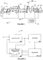
FIGURE 1 illustrates an examplepaper production system 100 according to one embodiment of this disclosure. The embodiment of thepaper production system 100 shown inFIGURE 1 is for illustration only. Other embodiments of thepaper production system 100 may be used without departing from the scope of this disclosure. - In this example, the
paper production system 100 includes apaper machine 102, acontrol system 104, and anetwork 105. Thepaper machine 102 includes various components used to produce a paper product. In this example, the various components may be used to produce apaper sheet 106 collected at areel 108. Thecontrol system 104 monitors and controls the operation of thepaper machine 102. This may help to maintain or increase the quality of thepaper sheets 106 produced by thepaper machine 102. - As shown in
FIGURE 1 , thepaper machine 102 includes aheadbox 110, which distributes a pulp suspension uniformly across the machine onto a continuous moving wire screen or mesh. The pulp suspension entering theheadbox 110 may contain, for example, 0.2-3% wood fibres and/or other solids, with the remainder of the suspension being water. Theheadbox 110 may include an array ofdilution actuators 112, which distributes dilution water into the pulp suspension across the sheet. The dilution water may be used to help ensure that the resultingpaper sheet 106 has a more uniform basis weight across the sheet in the cross direction (CD). Theheadbox 110 may also include an array ofslice lip actuators 114, which controls a slice opening across the machine from which the pulp suspension exits theheadbox 110 onto the moving wire screen or mesh. The array ofslice lip actuators 114 may also be used to control the CD basis weight of thepaper sheet 106. - An array of
steam actuators 116 produces hot steam that penetrates thepaper sheet 106 and releases the latent heat in the steam into thepaper sheet 106, thereby increasing the temperature of thepaper sheet 106 in sections across the sheet. The increase in temperature may allow for easier cross direction removal of water from thepaper sheet 106. An array ofrewet shower actuators 118 adds small droplets of water (which may be air atomized) onto the surface of thepaper sheet 106. The array ofrewet shower actuators 118 may be used to control the moisture CD profile of thepaper sheet 106, reduce or prevent over-drying of thepaper sheet 106, or correct any dry streaks in thepaper sheet 106. Thepaper sheet 106 is often passed through several nips of counter rotating rolls. An array ofinduction heating actuators 120 heats the shell surface of an iron roll across the machine. As the roll surface locally heats up, the roll diameter is locally expanded and hence increases nip pressure, which in turn locally compresses thepaper sheet 106. The array ofinduction heating actuators 120 may therefore be used to control the caliper (thickness) CD profile of thepaper sheet 106. Additional components could be used to further process thepaper sheet 106, such as a supercalender for improving the paper sheet's thickness, smoothness, and gloss. - This represents a brief description of one type of
paper machine 102 that may be used to produce a paper product. Additional details regarding this type ofpaper machine 102 are well-known in the art and are not needed for an understanding of this disclosure. Also, this represents one specific type ofpaper machine 102 that may be used in thesystem 100. Other machines or devices could be used that include any other or additional components for producing a paper product. In addition, this disclosure is not limited to use with systems for producing paper products and could be used with systems that produce other items or materials, such as plastic, textiles, metal foil or sheets, or other or additional materials. - In order to control the paper-making process, the properties of the
paper sheet 106 may be constantly or repeatedly measured and thepaper machine 102 adjusted to ensure sheet quality. This control may be achieved by measuring sheet properties at various stages in the manufacturing process. This information may then be used to adjust various actuators 112-120 within thepaper machine 102 to compensate for any variations in the sheet properties from desired targets. - As shown in
FIGURE 1 , thepaper machine 102 includes two scanners 122-124, each of which may include a set of sensors. The scanners 122-124 are capable of scanning thepaper sheet 106 and measuring one or more characteristics of thepaper sheet 106. For example, the scanners 122-124 could carry sensors for measuring the weight, moisture, caliper (thickness), gloss, smoothness, or any other or additional characteristics of thepaper sheet 106. Each of the scanners 122-124 includes any suitable structure or structures for measuring or detecting one or more characteristics of thepaper sheet 106, such as sets or arrays of sensors. A scanning set of sensors represents one particular embodiment for measuring sheet properties. Other embodiments could include using stationary sets or arrays of sensors. Each of these embodiments may produce one or more arrays of measurements representing a CD profile. The cross direction (CD) in thesystem 100 is typically perpendicular to the machine direction (MD) in thesystem 100. - The
control system 104 is coupled to the scanners 122-124. Thecontrol system 104 is capable of altering the operation of thepaper machine 102 based on the measurements taken by the scanners 122-124. For example, thecontrol system 104 could adjust the operation of the actuators 112-120 to achieve a desired result, such as apaper sheet 106 with desired or specified characteristics. Thecontrol system 104 includes any hardware, software, firmware, or combination thereof for controlling the operation of thepaper machine 102. One example embodiment of thecontrol system 104 is shown inFIGURE 2 , which is described below. - Among other things, the scanners 122-124 may not be synchronized with the
control system 104. For example, thecontrol system 104 may operate at a sampling rate, which could be fixed. In these embodiments, thecontrol system 104 includes a measurement predictor that provides estimated measurements that are synchronized with the sampling rate of thecontrol system 104. For example, the measurement predictor may predict the measurement data from one or more of the scanners 122-124 at the sampling instances (the times that the measurement data are sampled) of thecontrol system 104. As a particular example, the measurement predictor may use a process model (such as a model of the paper machine's operation) and historical data (such as prior control signals generated by the control system 104) to estimate what the measurements from a sensor would likely be at the sampling instances of the controller. Later, when the sensor provides actual measurement data to thecontrol system 104, the measurement predictor may update a prior predicted measurement using the new measurement data. Thecontrol system 104 may operate using the estimated and updated measurements. In this way, thecontrol system 104 may operate using multiple sets of sensors, and the sets of sensors may be asynchronous (not synchronized with the control system 104). Moreover, thecontrol system 104 could use the estimated and updated measurements in a synchronous manner, whether the samples are made at a fixed or variant sampling rate. - A
network 105 is coupled to thecontrol system 104, the actuators 112-120, and the scanners 122-124. Thenetwork 105 facilitates communication between components ofsystem 100. For example, thenetwork 105 may communicate Internet Protocol (IP) packets, frame relay frames, Asynchronous Transfer Mode (ATM) cells, or other suitable information between network addresses. Thenetwork 105 may include one or more local area networks (LANs), metropolitan area networks (MANs), wide area networks (WANs), all or a portion of a global network such as the Internet, or any other communication system or systems at one or more locations. Thenetwork 105 may also operate according to any appropriate type of protocol or protocols, such as Ethernet, IP, X.25, frame relay, or any other packet data protocol. - Although
FIGURE 1 illustrates one example of apaper production system 100, various changes may be made toFIGURE 1 . For example, other systems could be used to produce paper products or other products. Also, while shown as including two sets of sensors (scanners 122-124), theproduction system 100 could include more than two sets of sensors (whether scanning or stationary). In addition, the sensors could be located in any suitable locations in thesystem 100. -
FIGURE 2 illustrates anexample control system 104 in a paper production system according to one embodiment of this disclosure. Thecontrol system 104 shown inFIGURE 2 is for illustration only. Other embodiments of thecontrol system 104 could be used without departing from the scope of this disclosure. Also, for ease of explanation, thecontrol system 104 is described with respect to thepaper production system 100 ofFIGURE 1 . Thecontrol system 104 could be used with any other suitable device or system. - As shown in
FIGURE 2 , thecontrol system 104 includes acontroller 202. Thecontroller 202 is capable of controlling the operation of a process 204 (such as the process performed by the paper machine 102). For example, thecontroller 202 may receive inputs identifying the current value of a variable (such as a characteristic of the paper sheet 106). Based on the inputs, thecontroller 202 may adjust the operation of theprocess 204 so that the variable remains at or near a specified setpoint value (YSP). Thecontroller 202 may perform these actions at a particular rate, such as when thecontroller 202 uses the predicted states/measurements and generates a corresponding output at a specified sampling rate. This rate defines an interval of time, which may be referred to as a "control interval." Thecontroller 202 includes any hardware, software, firmware, or combination thereof for controlling one or more aspects of a process. Thecontroller 202 could, for example, represent an output feedback controller or a state feedback controller. As particular examples, thecontroller 202 could represent a multivariable model predictive controller (such as a multivariable cross-direction model predictive controller), a proportional-integral-derivative controller, or an H-infinity controller. - The output of the
controller 202 is provided to theprocess 204. In general, theprocess 204 represents a process that operates using the output of thecontroller 202, where the operation of theprocess 204 changes based on the controller output. In this example, theprocess 204 represents thepaper machine 102 of thepaper production system 100, where thecontroller 202 adjusts the operation of one or more components of thepaper machine 102 to alter the production of apaper sheet 106. - The scanners 122-124 generate and provide measurement data based on the currently executing
process 204. For example, the scanners 122-124 may represent sets of sensors that measure various characteristics of thepaper sheet 106 being produced by thepaper machine 102. The measurement data could represent synchronous or asynchronous data. For example, the scanners 122-124 could operate using different scanning times, meaning the scanners 122-124 require different amounts of time to generate measurement data. As another example, the scanners 122-124 could operate using identical but unaligned scanning times, meaning the scanners 122-124 require the same amount of time to generate measurement data but the time intervals are not aligned. Each of the scanners 122-124 may operate using any suitable scanning time, such as an interval of 10-30 seconds between measurements. - In these or other situations, the measurement data output by one or more of the scanners 122-124 may not be aligned or synchronized with the control interval of the
controller 202. Ameasurement predictor 206 in thecontrol system 104 is used to compensate for any asynchronous behavior of the scanners 122-124. For example, themeasurement predictor 206 may be synchronized with the sampling rate of thecontroller 202. Using information such as a model of theprocess 204 and historical outputs from thecontroller 202, themeasurement predictor 206 may predict the measurement data from one or more sensors, such as the sets of sensor in the scanners 122-124. This estimated measurement data may then be provided to thecontroller 202 for use. When a sensor provides actual measurement data to themeasurement predictor 206, themeasurement predictor 206 may update the prior predicted measurement data using the new measurement data from the sensor. In this way, themeasurement predictor 206 allows measurement data from one or multiple asynchronous sensors to be provided to and used by thecontroller 202. - The
measurement predictor 206 includes any hardware, software, firmware, or combination thereof for predicting at least some of the measurements made by one or more sensors. Themeasurement predictor 206 could, for example, include one ormore processor 208 and one ormore memories 210 capable of storing information and instructions used by the processor(s) 208. One example embodiment of themeasurement predictor 206 is shown inFIGURE 3 , which is described below. - Although
FIGURE 2 illustrates one example of acontrol system 104 in a paper production system, various changes may be made toFIGURE 2 . For example, thecontrol system 104 could include any number ofcontrollers 202, processes 204, scanners 122-124, andmeasurement predictors 206. -
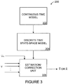
FIGURE 3 illustrates anexample measurement predictor 206 in a control system according to one embodiment of this disclosure. The embodiment of themeasurement predictor 206 shown inFIGURE 3 is for illustration only. Other embodiments of themeasurement predictor 206 could be used without departing from the scope of this disclosure. Also, for ease of explanation, themeasurement predictor 206 ofFIGURE 3 is described as operating in thecontrol system 104 ofFIGURE 2 in thepaper production system 100 ofFIGURE 1 . Themeasurement predictor 206 could be used in any other suitable device or system. - As shown in
FIGURE 3 , themeasurement predictor 206 includes acontinuous time model 302. Thecontinuous time model 302 represents a mathematical model of the process 204 (which may represent the process implemented by thepaper machine 102 ofFIGURE 1 ). Thecontinuous time model 302 may, for example, mathematically represent theprocess 204 using a transfer function modeled in the continuous time domain. - The
continuous time model 302 is used to define a discrete time state-space model 304 based on asynchronous sampling intervals. The discrete time state-space model 304 represents another mathematical model of theprocess 204. For example, the discrete time state-space model 304 may mathematically represent theprocess 204 using a transfer function model in the discrete time domain. - The
measurement predictor 206 also includes an estimation/correction unit 306. The estimation/correction unit 306 may be used to estimate the measurement data from one or more sensors, such as the sets of sensors in the scanners 122-124. The estimation/correction unit 306 may also update or correct prior estimated measurement data using actual measurement data received from the sensors. In this example, the estimation/correction unit 306 may estimate measurement data from a sensor using the discrete time state-space model 304 and historical controller values UH, which represent the prior control signals output by thecontroller 202 for controlling theprocess 204. The historical controller values UH could, for example, be stored in a buffer associated with themeasurement predictor 206. In some embodiments, these values are used in conjunction with the discrete time state-space model 304 to estimate or predict one or more measurements (Ỹ) from one or more sensors. The predicted measurements are then provided to the controller 202 (such as when thecontroller 202 is an output feedback controller). In other embodiments, the discrete time state-space model 304 could be used to estimate one or more states (X̂), which are provided to the controller 202 (such as when the controller is a state feedback controller). When measurement data from a sensor is received, themeasurement predictor 206 may update the previously estimated measurements or states for that sensor. This allows thecontroller 202 to use the appropriate measurements or states when controlling theprocess 204. - In particular embodiments, the models 302-304 could be stored in the
memory 210 and operated by theprocessor 208 of themeasurement predictor 206. Also, the estimation/correction unit 306 could be executed by theprocessor 208 of themeasurement predictor 206. Additional details regarding the operation of themeasurement predictor 206 are shown inFIGURES 4 , 5A, and 5B, which are described in more detail below. - Although
FIGURE 3 illustrates one example of ameasurement predictor 206 in a control system, various changes may be made toFIGURE 3 . For example, other or additional components could be used in themeasurement predictor 206 or to form themeasurement predictor 206. -
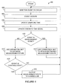
FIGURE 4 illustrates anexample method 400 for controlling a paper machine or other machine using measurement predictions based on asynchronous sensor information according to one embodiment of this disclosure. For ease of explanation, themethod 400 is described with respect to themeasurement predictor 206 in thecontrol system 104 ofFIGURE 2 operating in theproduction system 100 ofFIGURE 1 . Themethod 400 could be used by any other suitable device and in any other suitable system. - The
measurement predictor 206 waits for an event to occur atstep 402. This may include, for example, themeasurement predictor 206 waiting for a measurement event (such as receipt of measurement data from a sensor or set of sensors) or waiting for a controller execution event (use of measurement data by a controller). An event then occurs atstep 404. This may include, for example, themeasurement predictor 206 receiving measurement data from a sensor or set of sensors. - The
measurement predictor 206 updates the current sampling time of the sensor(s) atstep 406 and updates a discrete time model atstep 408. This may include, for example, themeasurement predictor 206 using thecontinuous time model 302 to generate the discrete time state-space model 304. - If the event that occurs is a measurement event at
step 410, themeasurement predictor 206 uses a correction unit to update a prior estimated measurement or state using actual measurement data at step 412. This may include, for example, the estimation/correction unit 306 using the actual measurement data from a sensor to correct a prior estimated measurement or state. Themeasurement predictor 206 may then return to step 402. In other embodiments, if the measurement event coincides with a controller execution event, themeasurement predictor 206 outputs the corrected measurement data to the controller at steps 416-418. Thecontroller 202 may then operate using the corrected measurement data to control theprocess 204. - If the event that occurs is not a measurement event at
step 410, themeasurement predictor 206 uses an estimation unit to estimate a measurement or state atstep 414. This may include, for example, the estimation/correction unit 306 using the updated discrete time state-space model 304 and historical controller values UH to predict what the measurement data from the sensor(s) might be. If the event is a controller execution event atstep 416, themeasurement predictor 206 outputs the predicted measurement data to the controller atstep 418. Thecontroller 202 may then operate using the predicted measurement data to control theprocess 204. - If the event that occurs is a measurement event at
step 410, themeasurement predictor 206 uses a correction unit to update a prior estimated measurement or state using actual measurement data atstep 414. This may include, for example, the estimation/correction unit 306 using the actual measurement data from a sensor to correct a prior estimated measurement or state. If the measurement event coincides with the controller execution event, themeasurement predictor 206 outputs the corrected measurement data to the controller atstep 416. Thecontroller 202 may then operate using the corrected measurement data to control theprocess 204. - In this way, the
measurement predictor 206 may provide estimated and updated measurement data to thecontroller 202 as needed. This flexibility allows themeasurement predictor 206 to provide measurement data from scanners 122-124 to thecontroller 202, even when the scanners 122-124 are asynchronous compared to thecontroller 202. - Although
FIGURE 4 illustrates one example of amethod 400 for controlling a paper machine or other machine using measurement predictions based on asynchronous sensor information, various changes may be made toFIGURE 4 . For example, themeasurement predictor 206 may use themethod 400 ofFIGURE 4 to process data from any number of scanners or sensors. - Returning to
FIGURE 3 , the following represents additional details regarding one specific implementation of themeasurement predictor 206 that operates according to themethod 400 ofFIGURE 4 . The additional details that follow are for illustration and explanation only. Other embodiments of themeasurement predictor 206 could be used without departing from the scope of this disclosure. - In particular embodiments, the following transfer function model in the continuous time domain may be used as the continuous time model 302:

particular model 302,


controller 202 to actuator arrays in the process 204 (such as components 110-120 in the paper machine 102). The disturbance profiles represent the present or current values of disturbances in theprocess 204, which represent unpredictable or random fluctuations in theprocess 204. Also, Ny and Nu represent the number of properties measured by the sensors and the number of actuator arrays, respectively. Further, m represents the resolution of the sensors, and nj represents the number of actuators in the jth actuator array. Although different sensors (such as scanners from different vendors) may have different resolutions, it is typically possible to up-sample or down-sample measurements so that all sensors have a common resolution. The common resolution could, for example, be at least three times the largest actuator number in all actuator arrays. Beyond that, Gij ∈ C m×nj (where i=1,...,Ny and j=1,...,Nu ) represents the ijth subplant's spatial matrix response, where a subplant represents a portion of theprocess 204 monitored by one or more sensor arrays. In addition, hij(s) represents the ijth subplant's dynamical response, which may be defined as:
- Based on Equation (2), the ijth subplant's transfer function can be expressed in the following state-space format:


- If the discrete time state-
space model 304 is based on a fixed control interval Tc (which could equal an integer multiple of a scanning/sampling time Ts of a sensor), the discrete time state-space model 304 could be defined as follows:


correction unit 306 may be used in themeasurement predictor 206. The third describes how to expand the above techniques into multi-dimensional systems (systems with multiple sensor arrays). - In general, predicted measurements can be accurately obtained based on the continuous model from Equations (3) and (4) since the time delay Td can be any positive number. However, in the discrete time domain, the quotient


- In another example, the function u(t) can be modified by defining u1(t)=u(t+pTc) to represent the integer portion of the time delay Td and by defining a virtual input v(t)=u1 (t+Tf) to represent the fractional portion of the time delay Td. By using the virtual input, there is no delay between the output y(t) and the virtual input v(t), meaning

- It is possible to express the dynamical response of a system using the following state-space model in the continuous time domain:


- The above could be extended to multiple-input, multiple-output systems. For example, the states for each subplant in a multiple-input, multiple-output system can be updated separately, and all subplants could be updated at the control action time. In other words, the states and measurements are updated using a variant sampling time T1 (equal to Tf or Tc-Tf), such as:


- This has described how to accurately predict measurements in the discrete time domain for a single-input, single-output system. The following describes how the estimation/
correction unit 306 may be used in themeasurement predictor 206. As noted above, one or more of the scanners 122-124 may not be synchronized with thecontroller 202, and themeasurement predictor 206 may predict the outputs of the scanners 122-124 and provide the predicted values to thecontroller 202. The estimation/correction unit 306 then updates or corrects the predicted values when actual measurements from the scanners 122-124 are received. - During a fixed control interval Tc, several different things could occur. A virtual input (which is the controller output delayed by the particular time delay for each subplant, where the time period between a virtual input event and a controller action event is the fractional time delay of a subplant) and one or more sensor outputs could be received. In particular embodiments, multiple sensor outputs could be received, but only the latest or most recent one is relevant. The virtual input could occur earlier than the sensor output, at the same time as the sensor output, or after the sensor output. Each fixed control interval Tc is divided into two or three portions, depending on when the virtual input and sensor output occur. These times are used as variant sampling times and for predicting the states and measurements as described above. However, when the sensor output occurs, the states may be corrected by the estimation/
correction unit 306 using the new measurements. For example, the estimation/correction unit 306 may operate to implement the following:
- As a particular example, the measurements at time t=Tc may be predicted as follows. Equations (14) and (15) are converted from the continuous time domain to the discrete time domain with a sampling time T1 . The measurement at time t=T1 can be predicted as:


controller 202. A similar process could be used to predict the measurements at times t=2Tc, 3Tc,.... A similar process could also be used with multiple-input, multiple-output systems having multiple asynchronous sensors. - Finally, the above techniques may be expanded for use in multi-dimensional systems with multiple sensor arrays. For example, the scalar input u and scalar output y may be replaced with a vector input U and a vector output Y, respectively. Accurately predicting the measurements at time t=Tc could occur as follows. Equations (3) and (4) are converted from the continuous time domain to the discrete corrected states x̂ij (t|t) (such as at the beginning of times T2 , T6, and T10 in FIGURE 5B) . In particular embodiments, the predicted measurements may only be updated when a control action event occurs.
- As a particular example, the measurements at time t=Tc may be predicted as follows. Equations (14) and (15) are converted from the continuous time domain to the discrete time domain with a sampling time T1 . The measurement at time t=T1 can be predicted as:


controller 202. A similar process could be used to predict the measurements at times t=2Tc,3Tc,.... A similar process could also be used with multiple-input, multiple-output systems having multiple asynchronous sensors. - Finally, the above techniques may be expanded for use in multi-dimensional systems with multiple sensor arrays. For example, the scalar input u and scalar output y may be replaced with a vector input U and a vector output Y, respectively. Accurately predicting the measurements at time t=Tc could occur as follows. Equations (3) and (4) are converted from the continuous time domain to the discrete time domain with a sampling time T1 . The measurements at time t=T1 can be predicted as:


- It may be advantageous to set forth definitions of certain words and phrases used throughout this patent document. The term "couple" and its derivatives refer to any direct or indirect communication between two or more elements, whether or not those elements are in physical contact with one another. The terms "include" and "comprise," as well as derivatives thereof, mean inclusion without limitation. The term "or" is inclusive, meaning and/or. The phrases "associated with" and "associated therewith," as well as derivatives thereof, may mean to include, be included within, interconnect with, contain, be contained within, connect to or with, couple to or with, be communicable with, cooperate with, interleave, juxtapose, be proximate to, be bound to or with, have, have a property of, or the like. The term "controller" means any device, system, or part thereof that controls at least one operation. A controller may be implemented in hardware, firmware, software, or some combination of at least two of the same. The functionality associated with any particular controller may be centralized or distributed, whether locally or remotely.
- While this disclosure has described certain embodiments and generally associated methods, alterations and permutations of these embodiments and methods will be apparent to those skilled in the art. Other changes, substitutions, and alterations are also possible without departing from the invention as defined by the following claims.
includes any type of medium capable of being accessed by a computer, such as read only memory (ROM), random access memory (RAM), a hard disk drive, a compact disc (CD), a digital video disc (DVD), or any other type of memory. - It may be advantageous to set forth definitions of certain words and phrases used throughout this patent document. The term "couple" and its derivatives refer to any direct or indirect communication between two or more elements, whether or not those elements are in physical contact with one another. The terms "include" and "comprise," as well as derivatives thereof, mean inclusion without limitation. The term "or" is inclusive, meaning and/or. The phrases "associated with" and "associated therewith," as well as derivatives thereof, may mean to include, be included within, interconnect with, contain, be contained within, connect to or with, couple to or with, be communicable with, cooperate with, interleave, juxtapose, be proximate to, be bound to or with, have, have a property of, or the like. The term "controller" means any device, system, or part thereof that controls at least one operation. A controller may be implemented in hardware, firmware, software, or some combination of at least two of the same. The functionality associated with any particular controller may be centralized or distributed, whether locally or remotely.
Claims (10)
- A method, comprising:repeatedly updating a discrete time model (304) of a process (204) to be controlled using a continuous time model (302) of the process (204), wherein the discrete time model is updated at multiple sampling times, and wherein different sampling times are associated with different types of events;predicting measurements or states to be used by a controller (202) to control the process (204), the predicted measurements or states generated using the repeatedly updated discrete time model (304) of the process (204);providing the predicted measurements or states to the controller (202) such that the controller (202) uses the predicted measurements or states at a sampling rate of the controller (202); andupdating at least some of the predicted measurements or states using measurements associated with a characteristic of an item from a sensor.
- The method of Claim 1, wherein:the controller has a control interval Tc ;the process to be controlled has a time delay Td that is larger than the control interval Tc such that Td =pTc +Tf, where p is a positive integer and Tf represents an amount of time in a fractional portion of one control interval Tc within the time delay Td ; andthe multiple types of events comprise:reaching a start or an end of a current control interval Tc ;receiving one of the measurements from the sensor; andreaching a time equal to the start of the current control interval Tc plus the amount of time Tf.
- The method of Claim 1, wherein the measurements are received from a plurality of sensors (122, 124), at least two of the sensors (122, 124) having different sampling times for generating their measurements.
- The method of Claim 1, further comprising:sampling the predicted measurements or states at the controller (202); andgenerating control signals for controlling the process (204) using the sampled measurements or states; andwherein predicting the measurements or states comprises generating at least some of the predicted measurements or states using the model and at least some of the control signals.
- The method of Claim 4, wherein the sampling rate of the controller (202) comprises a varying sampling rate.
- The method of Claim 1, wherein a time interval between measurements output by the sensor is a non-integer multiple of a time interval between outputs of the controller (202).
- An apparatus, comprising:at least one memory (210) operable to store a continuous time model (302) representing a process (204) controlled by a controller (202); andat least one processor (208) operable to:repeatedly update a discrete time model (304) of the process using the continuous time model (302), wherein the at least one processor is operable to update the discrete time model at multiple sampling times, and wherein different sampling times are associated with different types of events;predict measurements or states to be used by the controller (202) to control the process (204), the predicted measurements or states generated using the repeatedly updated discrete time model (304);provide the predicted measurements or states to the controller (202) such that the controller (202) uses the predicted measurements or states at a sampling rate of the controller (202); andupdate at least some of the predicted measurements or states using measurements associated with a characteristic of an item from a sensor.
- The apparatus of Claim 7, wherein:the controller (202) is operable to use the predicted measurements or states and generate control signals for controlling the process (204) using the sampled measurements or states; andthe at least one processor (208) is operable to predict the measurements or states by generating at least some of the predicted measurements or states using the model and at least some of the control signals.
- The apparatus of Claim 7, wherein at least one of:a time interval between measurements output by the sensor is a non-integer multiple of a time interval between outputs of the controller (202); anda time delay associated with the process (204) is a non-integer multiple of the time interval between outputs of the controller (202).
- A computer program embodied on a computer readable medium and operable to be executed by a processor, the computer program comprising computer readable program code for:repeatedly updating a discrete time model (304) of a process (204) to be controlled using a continuous time model (302) of the process (204), wherein the discrete time model is updated at multiple sampling times, and wherein different sampling times are associated with different types of events;predicting measurements or states to be used by a controller (202) to control the process (204), the predicted measurements or states generated using the repeatedly updated discrete time model (304) of the process (204);providing the predicted measurements or states to the controller (202) such that the controller (202) uses the predicted measurements or states at a sampling rate of the controller (202); andupdating at least some of the predicted measurements or states using measurements associated with a characteristic of an item from a sensor.
Applications Claiming Priority (2)
| Application Number | Priority Date | Filing Date | Title |
|---|---|---|---|
| US11/413,524 US7689296B2 (en) | 2006-04-28 | 2006-04-28 | Apparatus and method for controlling a paper machine or other machine using measurement predictions based on asynchronous sensor information |
| PCT/IB2007/001168 WO2008041067A2 (en) | 2006-04-28 | 2007-04-27 | Method for controlling a process using measurement predictions |
Publications (2)
| Publication Number | Publication Date |
|---|---|
| EP2024560A2 EP2024560A2 (en) | 2009-02-18 |
| EP2024560B1 true EP2024560B1 (en) | 2017-11-15 |
Family
ID=38649366
Family Applications (1)
| Application Number | Title | Priority Date | Filing Date |
|---|---|---|---|
| EP07734484.4A Ceased EP2024560B1 (en) | 2006-04-28 | 2007-04-27 | Method and apparatus for controlling a process using measurement predictions |
Country Status (5)
| Country | Link |
|---|---|
| US (1) | US7689296B2 (en) |
| EP (1) | EP2024560B1 (en) |
| JP (1) | JP5058249B2 (en) |
| CA (1) | CA2650657C (en) |
| WO (1) | WO2008041067A2 (en) |
Families Citing this family (19)
| Publication number | Priority date | Publication date | Assignee | Title |
|---|---|---|---|---|
| US7513975B2 (en) * | 2003-06-25 | 2009-04-07 | Honeywell International Inc. | Cross-direction actuator and control system with adaptive footprint |
| US8753482B2 (en) * | 2008-04-30 | 2014-06-17 | Honeywell International Inc. | Method and apparatus for treatment of paper stock |
| JP5278904B2 (en) * | 2009-03-24 | 2013-09-04 | インターナショナル・ビジネス・マシーンズ・コーポレーション | Hybrid system simulation method and simulation program |
| US8224476B2 (en) * | 2010-05-31 | 2012-07-17 | Honeywell Asca Inc. | Closed-loop monitoring and identification of CD alignment for papermaking processes |
| CA2808503A1 (en) * | 2010-08-20 | 2012-02-23 | Vigilent Corporation | Energy-optimal control decisions for hvac systems |
| US8805910B2 (en) * | 2011-03-04 | 2014-08-12 | Kylowave Inc. | System and method for generating discrete-time model (DTM) of continuous-time model (CTM) for a dynamical system |
| KR101367390B1 (en) * | 2012-02-28 | 2014-02-25 | 만도헬라일렉트로닉스(주) | Method detecting abnormality of multi-channel asynchronous sensor and steering safety apparatus using the same |
| US9511969B2 (en) | 2012-03-28 | 2016-12-06 | Honeywell Limited | Closed-loop alignment identification with adaptive probing signal design technique for web manufacturing or processing systems |
| US8702908B1 (en) | 2013-01-28 | 2014-04-22 | Abb Technology Ag | Reducing product variations via variance partition analysis |
| WO2015171624A1 (en) | 2014-05-05 | 2015-11-12 | Vigilent Corporation | Point-based risk score for managing environmental systems |
| US9540770B2 (en) * | 2014-09-25 | 2017-01-10 | Honeywell Limited | Modular sensing system for web-based applications |
| FR3028054B1 (en) * | 2014-11-05 | 2018-01-26 | Safran Aircraft Engines | IMPROVED CONTROLLER OF STATE OF A PILOT SYSTEM BY AN ORDER |
| US10174456B2 (en) * | 2016-09-23 | 2019-01-08 | Honeywell Limited | Technique to improve paper machine cross-directional model predictive control performance by creating a measurement profile reference trajectory |
| JP6874459B2 (en) * | 2017-03-27 | 2021-05-19 | セイコーエプソン株式会社 | Sheet manufacturing equipment and control method of seat manufacturing equipment |
| JP7062577B2 (en) * | 2018-11-21 | 2022-05-06 | 株式会社日立製作所 | Manufacturing condition identification system and method |
| CN110720096B (en) * | 2019-07-03 | 2022-07-08 | 深圳市速腾聚创科技有限公司 | Multi-sensor state estimation method and device and terminal equipment |
| JP7270322B2 (en) * | 2019-08-06 | 2023-05-10 | 東芝三菱電機産業システム株式会社 | data estimation controller |
| WO2023198269A1 (en) * | 2022-04-11 | 2023-10-19 | Abb Schweiz Ag | Method of producing a paper product and system for producing a paper product |
| WO2025242285A1 (en) * | 2024-05-21 | 2025-11-27 | Abb Schweiz Ag | A method for an industrial object in an industrial system |
Family Cites Families (8)
| Publication number | Priority date | Publication date | Assignee | Title |
|---|---|---|---|---|
| JPH117307A (en) * | 1997-06-17 | 1999-01-12 | Toshiba Corp | Model prediction apparatus and method |
| US6094604A (en) * | 1998-03-06 | 2000-07-25 | Honeywell Measurex Devron Inc. | Coordinated control of sheet properties by receiving a measured and broadcasted properties data, determining a control action, and broadcasting a predicted changes to other actuators |
| DE19913926A1 (en) | 1999-03-26 | 2000-09-28 | Voith Sulzer Papiertech Patent | Manufacture and control of quality in band of paper, requires sensors at headbox discharge, and locations throughout plant, measurements being computer coordinated and used in control model |
| US20030000669A1 (en) * | 2001-05-11 | 2003-01-02 | Invensys Systems, Inc. | Methods and systems for controlling paper quality by adjusting fiber filter parameters |
| WO2003096130A1 (en) | 2001-10-23 | 2003-11-20 | Brooks-Pri Automation, Inc. | Semiconductor run-to-run control system with state and model parameter estimation |
| US6807510B1 (en) * | 2003-05-05 | 2004-10-19 | Honeywell Acsa Inc. | Model predictive controller for coordinated cross direction and machine direction control |
| US20050193739A1 (en) * | 2004-03-02 | 2005-09-08 | General Electric Company | Model-based control systems and methods for gas turbine engines |
| US7877154B2 (en) * | 2005-09-30 | 2011-01-25 | Fisher-Rosemount Systems, Inc. | Method and system for controlling a batch process |
-
2006
- 2006-04-28 US US11/413,524 patent/US7689296B2/en active Active
-
2007
- 2007-04-27 WO PCT/IB2007/001168 patent/WO2008041067A2/en not_active Ceased
- 2007-04-27 JP JP2009507192A patent/JP5058249B2/en active Active
- 2007-04-27 EP EP07734484.4A patent/EP2024560B1/en not_active Ceased
- 2007-04-27 CA CA2650657A patent/CA2650657C/en active Active
Non-Patent Citations (1)
| Title |
|---|
| None * |
Also Published As
| Publication number | Publication date |
|---|---|
| US20070255446A1 (en) | 2007-11-01 |
| US7689296B2 (en) | 2010-03-30 |
| CA2650657C (en) | 2015-09-15 |
| EP2024560A2 (en) | 2009-02-18 |
| CA2650657A1 (en) | 2008-04-10 |
| WO2008041067A2 (en) | 2008-04-10 |
| WO2008041067A3 (en) | 2009-04-09 |
| JP2009535684A (en) | 2009-10-01 |
| JP5058249B2 (en) | 2012-10-24 |
Similar Documents
| Publication | Publication Date | Title |
|---|---|---|
| EP2024560B1 (en) | Method and apparatus for controlling a process using measurement predictions | |
| EP2013668B1 (en) | Apparatus and method for coordinating controllers to control a paper machine or other machine | |
| CA2647716C (en) | Fast performance prediction of multivariable model predictive controller for paper machine cross-directional processes | |
| US5400247A (en) | Adaptive cross-directional decoupling control systems | |
| US6807510B1 (en) | Model predictive controller for coordinated cross direction and machine direction control | |
| EP1941328B1 (en) | Automated tuning of large-scale multivariable model predictive controllers for spatially-distributed processes | |
| US5893055A (en) | Two-dimensional web property variation modeling and control | |
| EP3296821B1 (en) | Closed-loop model parameter identification techniques for industrial model-based process controllers | |
| CA2727396A1 (en) | Method and apparatus for reel building and roll runnability in moving web manufacturing | |
| EP2935693B1 (en) | Apparatus and method for controlling a property of an object | |
| EP3299910A1 (en) | Technique to improve paper machine cross- directional model predictive control performance by creating a measurement profile reference trajectory | |
| Arkun et al. | A novel approach to full CD profile control of sheet-forming processes using adaptive PCA and reduced-order IMC design | |
| CA2660414A1 (en) | Apparatus and method for caliper profile break recovery in a paper machine | |
| Corscadden et al. | Multivariable disturbance modelling for web processes | |
| Sunori et al. | Paper basis weight control in paper mill using dead time approximation and dead time compensation techniques | |
| JPH09192716A (en) | Looper multi-variable controller | |
| KJAER¹ et al. | FORMING PROCESSES | |
| Corscadden | Cross-Directional Estimation and Control of Web Forming Processes |
Legal Events
| Date | Code | Title | Description |
|---|---|---|---|
| PUAI | Public reference made under article 153(3) epc to a published international application that has entered the european phase |
Free format text: ORIGINAL CODE: 0009012 |
|
| 17P | Request for examination filed |
Effective date: 20081023 |
|
| AK | Designated contracting states |
Kind code of ref document: A2 Designated state(s): DE FI GB |
|
| RTI1 | Title (correction) |
Free format text: METHOD FOR CONTROLLING A PROCESS USING MEASUREMENT PREDICTIONS |
|
| R17D | Deferred search report published (corrected) |
Effective date: 20090409 |
|
| DAX | Request for extension of the european patent (deleted) | ||
| RBV | Designated contracting states (corrected) |
Designated state(s): DE FI GB |
|
| 17Q | First examination report despatched |
Effective date: 20110518 |
|
| REG | Reference to a national code |
Ref country code: DE Ref legal event code: R079 Ref document number: 602007053037 Country of ref document: DE Free format text: PREVIOUS MAIN CLASS: D21F Ipc: G05B0013040000 |
|
| GRAP | Despatch of communication of intention to grant a patent |
Free format text: ORIGINAL CODE: EPIDOSNIGR1 |
|
| RIC1 | Information provided on ipc code assigned before grant |
Ipc: G05B 13/04 20060101AFI20170531BHEP |
|
| INTG | Intention to grant announced |
Effective date: 20170704 |
|
| GRAS | Grant fee paid |
Free format text: ORIGINAL CODE: EPIDOSNIGR3 |
|
| GRAA | (expected) grant |
Free format text: ORIGINAL CODE: 0009210 |
|
| AK | Designated contracting states |
Kind code of ref document: B1 Designated state(s): DE FI GB |
|
| REG | Reference to a national code |
Ref country code: GB Ref legal event code: FG4D |
|
| REG | Reference to a national code |
Ref country code: DE Ref legal event code: R096 Ref document number: 602007053037 Country of ref document: DE |
|
| REG | Reference to a national code |
Ref country code: DE Ref legal event code: R026 Ref document number: 602007053037 Country of ref document: DE |
|
| PLBI | Opposition filed |
Free format text: ORIGINAL CODE: 0009260 |
|
| PLAX | Notice of opposition and request to file observation + time limit sent |
Free format text: ORIGINAL CODE: EPIDOSNOBS2 |
|
| 26 | Opposition filed |
Opponent name: VAILLANT GMBH Effective date: 20180815 |
|
| PGFP | Annual fee paid to national office [announced via postgrant information from national office to epo] |
Ref country code: FR Payment date: 20171018 Year of fee payment: 10 |
|
| PLBB | Reply of patent proprietor to notice(s) of opposition received |
Free format text: ORIGINAL CODE: EPIDOSNOBS3 |
|
| PGFP | Annual fee paid to national office [announced via postgrant information from national office to epo] |
Ref country code: DE Payment date: 20190430 Year of fee payment: 13 Ref country code: FI Payment date: 20190418 Year of fee payment: 13 |
|
| GBPC | Gb: european patent ceased through non-payment of renewal fee |
Effective date: 20190427 |
|
| PLAB | Opposition data, opponent's data or that of the opponent's representative modified |
Free format text: ORIGINAL CODE: 0009299OPPO |
|
| R26 | Opposition filed (corrected) |
Opponent name: VAILLANT GMBH Effective date: 20180815 |
|
| PG25 | Lapsed in a contracting state [announced via postgrant information from national office to epo] |
Ref country code: GB Free format text: LAPSE BECAUSE OF NON-PAYMENT OF DUE FEES Effective date: 20190427 |
|
| PLBP | Opposition withdrawn |
Free format text: ORIGINAL CODE: 0009264 |
|
| PLBD | Termination of opposition procedure: decision despatched |
Free format text: ORIGINAL CODE: EPIDOSNOPC1 |
|
| REG | Reference to a national code |
Ref country code: DE Ref legal event code: R100 Ref document number: 602007053037 Country of ref document: DE |
|
| PLBM | Termination of opposition procedure: date of legal effect published |
Free format text: ORIGINAL CODE: 0009276 |
|
| 27C | Opposition proceedings terminated |
Effective date: 20200314 |
|
| REG | Reference to a national code |
Ref country code: DE Ref legal event code: R119 Ref document number: 602007053037 Country of ref document: DE |
|
| REG | Reference to a national code |
Ref country code: FI Ref legal event code: MAE |
|
| PG25 | Lapsed in a contracting state [announced via postgrant information from national office to epo] |
Ref country code: DE Free format text: LAPSE BECAUSE OF NON-PAYMENT OF DUE FEES Effective date: 20201103 Ref country code: FI Free format text: LAPSE BECAUSE OF NON-PAYMENT OF DUE FEES Effective date: 20200427 |