EP2024062B1 - Carbon dioxide capture and related processes - Google Patents
Carbon dioxide capture and related processes Download PDFInfo
- Publication number
- EP2024062B1 EP2024062B1 EP07835735A EP07835735A EP2024062B1 EP 2024062 B1 EP2024062 B1 EP 2024062B1 EP 07835735 A EP07835735 A EP 07835735A EP 07835735 A EP07835735 A EP 07835735A EP 2024062 B1 EP2024062 B1 EP 2024062B1
- Authority
- EP
- European Patent Office
- Prior art keywords
- carbon dioxide
- water
- mineral
- solution
- reacting
- Prior art date
- Legal status (The legal status is an assumption and is not a legal conclusion. Google has not performed a legal analysis and makes no representation as to the accuracy of the status listed.)
- Not-in-force
Links
Images


Classifications
-
- B—PERFORMING OPERATIONS; TRANSPORTING
- B01—PHYSICAL OR CHEMICAL PROCESSES OR APPARATUS IN GENERAL
- B01D—SEPARATION
- B01D53/00—Separation of gases or vapours; Recovering vapours of volatile solvents from gases; Chemical or biological purification of waste gases, e.g. engine exhaust gases, smoke, fumes, flue gases, aerosols
- B01D53/34—Chemical or biological purification of waste gases
- B01D53/46—Removing components of defined structure
- B01D53/62—Carbon oxides
-
- B—PERFORMING OPERATIONS; TRANSPORTING
- B01—PHYSICAL OR CHEMICAL PROCESSES OR APPARATUS IN GENERAL
- B01D—SEPARATION
- B01D2251/00—Reactants
- B01D2251/30—Alkali metal compounds
-
- B—PERFORMING OPERATIONS; TRANSPORTING
- B01—PHYSICAL OR CHEMICAL PROCESSES OR APPARATUS IN GENERAL
- B01D—SEPARATION
- B01D2257/00—Components to be removed
- B01D2257/50—Carbon oxides
- B01D2257/504—Carbon dioxide
-
- B—PERFORMING OPERATIONS; TRANSPORTING
- B01—PHYSICAL OR CHEMICAL PROCESSES OR APPARATUS IN GENERAL
- B01D—SEPARATION
- B01D2259/00—Type of treatment
- B01D2259/45—Gas separation or purification devices adapted for specific applications
- B01D2259/455—Gas separation or purification devices adapted for specific applications for transportable use
- B01D2259/4558—Gas separation or purification devices adapted for specific applications for transportable use for being employed as mobile cleaners for ambient air, i.e. the earth's atmosphere
-
- Y—GENERAL TAGGING OF NEW TECHNOLOGICAL DEVELOPMENTS; GENERAL TAGGING OF CROSS-SECTIONAL TECHNOLOGIES SPANNING OVER SEVERAL SECTIONS OF THE IPC; TECHNICAL SUBJECTS COVERED BY FORMER USPC CROSS-REFERENCE ART COLLECTIONS [XRACs] AND DIGESTS
- Y02—TECHNOLOGIES OR APPLICATIONS FOR MITIGATION OR ADAPTATION AGAINST CLIMATE CHANGE
- Y02C—CAPTURE, STORAGE, SEQUESTRATION OR DISPOSAL OF GREENHOUSE GASES [GHG]
- Y02C20/00—Capture or disposal of greenhouse gases
- Y02C20/40—Capture or disposal of greenhouse gases of CO2
Definitions
- the invention relates generally to the capture of carbon dioxide from the atmosphere and/or from point sources (e.g., power plants, chemical plants, natural gas fields, oil fields, industrial sites).
- point sources e.g., power plants, chemical plants, natural gas fields, oil fields, industrial sites.
- the present invention provides a process for capturing and storing carbon dioxide comprising:
- the carbon dioxide may be captured from the atmosphere and/or from the waste stream of a carbon dioxide point source (e.g., power plants, chemical plants, natural gas fields, oil fields, industrial sites, etc.).
- the processes involve capturing carbon dioxide using alkaline solutions (e.g., NaOH).
- alkaline solutions e.g., NaOH
- the carbon dioxide reacts with the alkaline solution to form a product (e.g., NaHCO 3 ).
- the alkaline solution may be made a number of different ways.
- products produced during processing may be used to add value beyond carbon dioxide capture, as described further below.
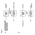
- FIGS. 1- 4 schematically illustrate general steps of the processes according to embodiments of the invention.
- FIG. 1 pertains to an embodiment of the invention in which an acidic species is neutralized.
- FIG. 2 shows an embodiment in which a sodium chloride solution is processed to produce sodium hydroxide (NaOH), chlorine gas (Cl 2 ), and hydrogen gas (H 2 ).
- FIG. 3 shows an embodiment in which a salt solution is processed, and acidic species and metal bicarbonate and/or metal carbonate are formed.
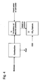
- FIG. 4 shows an embodiment in which biomass is added to water to form an alkaline solution.
- the term "acidic species” refers to dissolved species (e.g., ions) that contribute to the acidity of a solution.
- the term “alkaline species” refers to dissolved species (e.g., ions) that contribute to the alkalinity of a solution.
- Step 10 involves formation of an alkaline solution.
- Step 20 involves capturing carbon dioxide from the atmosphere and/or from the waste stream of a carbon dioxide point source.
- the carbon dioxide may be captured by reacting it with the alkaline species in the solution produced in Step 10 and/or dissolving it in the alkaline solution produced in step 10.
- Step 30 ( FIGS. 1A-1B ) involves secondary processing of products produced during the process. The steps are further described below.
- any suitable technique may be used to form the alkaline solution (e.g., a hydroxide solution such as sodium hydroxide).
- step 10 involves processing water having a sufficient concentration of ions from dissolved salts, for example, ions of chlorine, fluorine, bromine, sulfate, and nitrate, amongst others, to form the alkaline solution, as described further below.
- Water having a sufficient concentration of chlorine ions e.g., from NaCl
- the water e.g., "salt water” from an ocean or sea ( FIG.
- FIG. 1A may naturally have a sufficient concentration of ions from dissolved salts.
- FIG. 1B it may be preferable to add appropriate anions to the water (e.g., "fresh water”).
- halite (NaCl) of other types of salt may be added to the water.
- the water may be a river, lake, or aquifer and the salt may be a natural salt deposit.
- the body (or source) of water may be large to provide a sufficient supply of water for the process.
- the body of water may be an ocean, a sea, a lake, or a river. Water may be supplied from the body of water to a plant where the additional processing steps are performed.
- FIGS. 1-3 involve the processing of a salt solution into an acidic solution and an alkaline (i.e., a basic) solution. Electrochemical processes are used in the separation of a salt solution into an acidic and an alkaline (i.e., a basic) solution.
- FIGS. 1-4 involve the reaction of CO 2 with the alkaline species and/or the dissolution of CO 2 into the solution including alkaline species.
- the methods can involve neutralizing the alkaline species with CO 2 .
- NaOH forms the alkaline species
- the final step produces NaHCO 3 solution and/or Na 2 CO 3 solution. Therefore, embodiments of the invention may extend any known method of producing caustic soda (NaOH) to the production of sodium bicarbonate and/or disodium carbonate (thereby capturing CO 2 ) by adding one more processing step to the caustic soda.
- the process involves the co-production of sodium bicarbonate (and/or disodium carbonate), chlorine gas, and hydrogen gas by reacting the NaOH co-produced with chlorine gas and hydrogen gas with CO 2 from a source of CO 2 for the purpose of capturing and storing CO 2 and carbonate and bicarbonate species. Therefore, one embodiment of the invention constitutes the co-production of NaHCO 3 solution and/or Na 2 CO 3 solution with Cl 2 gas and H 2 gas with the capture of CO 2 .
- FIGS. 3A-3B it should be understood that though the above description relates to Cl 2 and H 2 , other suitable gases and corresponding acids may also be used in processes of the invention.
- FIGS. 3A-3B it may be preferable if chlorine is not produced when forming the alkaline solution.
- the products when forming the alkaline solution may be free of chlorine.
- the embodiments illustrated in FIG. 3A involves the separation of any salt (e.g., an organic salt like sodium acetate (CH 3 COONa) as depicted in FIG. 3B ) into an acidic solution and an alkaline or basic solution.
- any salt e.g., an organic salt like sodium acetate (CH 3 COONa) as depicted in FIG. 3B
- sodium hydroxide may be generated without using chlorine ions.
- an organic acid e.g., acetic acid, lactic acid, or formic acid
- sodium hydroxide CH 3 COO - + Na + + H 2 O ⁇ CH 3 COOH + NaOH
- the final step of the embodiments illustrated in FIGS. 3A-3B involves the reaction of the alkaline solution with CO 2 from a source of CO 2 for the purpose of capturing and storing the CO 2 as a carbonate or bicarbonate species.
- FIGS. 3A-3B illustrates the co-production of acid with metal bicarbonate or metal carbonate.
- the embodiments illustrated in FIGS. 3A-3B involve the processing of a salt solution (e.g., sodium acetate) into an alkaline or basic solution (e.g., metal hydroxide solution) and an acidic solution.
- the acid may be sold on the open market while the hydroxide specie are reacted to CO 2 to form MHCO 3 or MCO 3 , where M indicates the metal ion in the original salt.
- MHCO 3 or MCO 3 where M indicates the metal ion in the original salt.
- step 10 of FIGS. 1A-1B and 3A-3B may include an electrodialysis process such as electro-electrodialysis, salt splitting or bipolar membrane electrodialysis. These processes uses an applied voltage to drive opposite-charged ions in a salt solution in opposite directions through membranes engineered for high permeability of ions of a particular charge state. Charge-compensating ions are generated by the electrolysis of water, resulting in acid and base exit streams.
- a suitable process is described in " Electrodialysis Process With Bipolar Membranes (EDBM) in Environmental Protection - A Review", by Tongwen Xu, Resources, Conservation and Recycling (2002 ), which is incorporated herein by reference.
- the process may involve co-production of sulfuric acid and sodium hydroxide.
- the sulfuric acid may be produced from a reaction between metal sulfate salt (e.g., sodium sulfate) and water.
- metal sulfate salt e.g., sodium sulfate
- a bipolar membrane electrodialysis process may be used.
- a representative reaction is: Na 2 SO 4 + 2H 2 O ⁇ 2NaOH + H 2 SO 4 It should be understood that in any of the above reactions, sodium may be replaced with another suitable cation such as potassium.
- FIG. 4 can involve creating the alkaline solution by adding ash from biomass burning or biomass gasification to a suitable body of water (e.g., "fresh water” or “salt water”).
- the ash can be a source of metal cations (e.g., Ca 2+ , Mg 2+ , K + , Na + ) and carbonate ions (CO 3 2- ) .
- An alkaline (i.e., basic) solution can be produced by dissolving the ash in any some form of water (Step 10, FIG. 4 ).
- the process further comprises capturing carbon dioxide from a source of carbon dioxide by reacting it with the alkaline solution to form the bicarbonate or carbonate species (Step 20, FIG. 4 ).
- Step 20 involves capturing CO 2 using the alkaline solution produced in step 10.
- CO 2 may be reacted with alkaline species through a spray tower.
- step 20 involves adding the alkaline or basic solution (e.g., NaOH) produced in step 10 directly to a body of water (e.g., the ocean).
- the process will increase the concentration of hydroxide ions and cations (e.g., in the form of NaOH) relative to the concentration of hydrogen ions and anions (e.g., in the form of HCl) in the body of water.
- the process will have increased the alkalinity of the body of water.
- alkalinity 2[Ca 2+ ] + [K + ] + 2[Mg 2+ ] + [Na] - [Cl 1- ]-2[SO 4 2- ]
- the small excess charge of the cations over anions is mainly balanced by the concentrations of carbonate and bicarbonate ions.
- DIC dissolved inorganic carbon
- That partitioning shift decreases the concentration of CO 2 (aq), which is the fraction of DIC that is able to interact directly with the CO 2 (g) in the atmosphere.
- the surface water becomes under-saturated in CO 2 (aq) and additional CO 2 (g) dissolves from the atmosphere into the body of water.
- the quantity of additional atmospheric CO 2 (g) that dissolves into the body of water is related to the increase in alkalinity. Therefore, in one embodiment of this invention, the removal and neutralization (step 30, FIGS. 1A-1B ) of hydrochloric acid (HCl) from the ocean causes the water to remove CO 2 (g) from the atmosphere.
- the CO 2 that is removed from the atmosphere will be chemically stored in the body of water as dissolved organic carbon (CO 2 (aq), HCO 3 - , and CO 3 2- ).
- processes of the invention effectively accelerate the natural CO 2 (g) uptake process of a body of water (e.g., an ocean). Additionally, the processes can enable civilization to better control the pH of bodies of water (e.g., an ocean).
- a body of water e.g., an ocean
- the uptake of anthropogenic CO 2 causes the pH of bodies of water to drop.
- Removal and neutralization (step 30, FIGS. 1A-1B ) of acid (e.g., HCl) will cause the pH of surface water to rise, but the additional CO 2 that necessarily dissolves in the water will balance that rise in pH.
- acid e.g., HCl
- the pH can be maintained while the concentration of atmospheric CO 2 is brought down to the desired level.
- the embodiment of this invention illustrated in FIG. 4 can also be used to capture CO 2 by adding the ash-based alkaline solution to a body of water for the purpose of increasing the alkalinity of that water.
- the body of water may be under-saturated with respect to calcite (CaCO 3 ), though it should be understood that not all processes are so limited.
- CaCO 3 calcite
- the net result is the uptake of carbon dioxide from the atmosphere.
- the body of water used does not need to be under-saturated with respect to calcite in order to have carbon dioxide capture and storage.
- step 20 involves reacting the alkaline solution (e.g., sodium hydroxide or other suitable alkaline solution) with carbon dioxide from the atmosphere to produce a reaction product (e.g., sodium bicarbonate and/or disodium carbonate, or other suitable compound).
- a reaction product e.g., sodium bicarbonate and/or disodium carbonate, or other suitable compound.
- the reaction product is not used to re-generate the alkaline species which are used to capture carbon dioxide. That is, the reaction product is used for other purposes than re-generating alkaline species used to capture carbon dioxide.
- the reaction product may be disposed of and/or otherwise further processed.
- the reaction product may be disposed of by introducing the product into a suitable body of water (e.g., the ocean) or land-based environment (e.g., landfill, mine)
- a pool of highly concentrated sodium hydroxide may be collected.
- the pool may be exposed to the atmosphere causing the reaction to occur.
- the sodium hydroxide (or other suitable compound) may be sold and shipped to a carbon dioxide point source (e . g., power plants, chemical plants, natural gas fields, oil fields, industrial sites, etc.).
- the waste stream produced by the carbon dioxide point source may be reacted with a concentrated pool of sodium hydroxide to cause the reaction to occur.
- the reaction of sodium hydroxide with carbon dioxide thus, reduces the concentration of carbon dioxide in the atmosphere or in the waste stream of a carbon dioxide from a point source.
- the sodium bicarbonate and/or disodium carbonate that is formed from the reaction of the sodium hydroxide with the carbon dioxide may be added to the body of water, or otherwise collected and disposed.
- FIGS. 1 - 3 differ in how the non-alkaline products produced during the process are further processed.
- the chlorine gas and/or hydrogen gas produced is sold on the open market.
- the hydrogen gas produced may be combined with oxygen from the atmosphere to form water and useful energy according to the following reaction: 1 ⁇ 2 H 2 + 1 ⁇ 4 O 2 ⁇ 1 ⁇ 2 H 2 O
- the chlorine gas and hydrogen gas formed in step 10 may react to form HCl according to the following equation: 1 ⁇ 2 H 2 + 1 ⁇ 2 Cl 2 ⁇ HCl
- the chlorine gas and hydrogen gas formed in step 10 may be combined in a fuel cell or a hydrogen gas turbine that produces either HCl(g) or HCl(aq) and electricity that can be harnessed for use in other processing steps or otherwise utilized.
- the application of the HCl fuel cell will likely be a valuable element of the process because the electricity produced in the fuel cell may substantially decrease of the operational costs.
- the HCI produced in reaction by the combination of Cl 2 and H 2 can be removed for further processing (e.g., step 30, FIG. 1A-1B ).
- Such processing can ensure that the acid is not returned to the body of water.
- any chloride ion that returns to the body of water without a corresponding conservative cation can reverse gains achieved in the process by causing carbon dioxide to degas to the atmosphere. Therefore, the acid is typically disposed of in a way that effectively neutralizes the acid and/or combines its anions with conservative cations.
- Step 30 of FIGS. 1A-1B involves reacting HCl (or other acid) with a mineral containing reduced iron (Fe, Fe + , Fe 2+ ).
- Suitable rock or mineral sources include silicate mineral and/or rocks, mafic minerals (e.g., wustite, olivine, pyroxene, amphibole, biotite mica), magnetite, mafic and ultramafic rocks, serpentinites, basalts, and iron ores.
- step 30 of FIGS. 1A-1B may include the dissolution of any rock by HCl that combines the chlorine ions with conservative cations (e.g., Mg 2+ , Al 2+ , Al 3+ , Fe 2+ , Fe 3+ , K + , Ca 2+ , Na + etc.).
- conservative cations e.g., Mg 2+ , Al 2+ , Al 3+ , Fe 2+ , Fe 3+ , K + , Ca 2+ , Na + etc.
- the acid is disposed of by reacting with rocks and/or minerals (e.g., silicate rocks and/or minerals) in a reaction vessel.
- rocks and/or minerals e.g., silicate rocks and/or minerals
- the rocks and/or minerals are transported to the reaction vessel.
- the rocks and/or minerals may be processed to form smaller rocks and/or minerals.
- the rocks and/or minerals are combined with the acid, and the dissolution of the rocks and/or minerals neutralizes the acid.
- the acid is neutralized through reaction with and/or dissolution of rocks and/or minerals in-situ (i.e., rocks and/or minerals in their natural location).
- the acidic solution may be injected into or sprayed onto the rock and/or mineral (e.g., basaltic, ultramafic rock and/or mineral formations).
- the acid can be neutralized when it contacts the rock and/or mineral formation, while flowing through and/or across the rock and/or mineral formation.
- the seepage flow may be engineered such that that time scale of acid flow through the rock and/or mineral formation would be slow relative to the timescale of the rock and/or mineral dissolution. If the timescales are appropriately engineered, then the acid will be largely neutralized when the dissolution products reach a body of water (e.g., the ocean).
- the acid is disposed of in an exothermic reaction and also generates additional useful energy.
- the purpose of using reduced iron containing minerals and/or rocks is that the oxidation of the iron can be used to generate useful energy.
- mafic and ultramafic rock, basalt, and certain iron ore all contain reduced iron.
- the acid (e.g., HCl) solution can dissolve these minerals in reactions similar to the following dissolution reaction of HCl and olivine: (Mg,Fe) 2 SiO 4 +4HCl ⁇ 2(Mg,Fe)Cl 2 + SiO 2 + 2H 2 O During the dissolution process, the following reaction will sometimes occur as the Fe 2+ is oxidized to Fe 3+ by the formation of H 2 (g): Fe 2 SiO 4 + 6HCl ⁇ 2FeCl 3 + SiO 2 + 2H 2 O + H 2 That reaction results in the production of H 2 .
- the fraction of the Fe 2+ that is not oxidized during the dissolution reaction described above can be used in a fuel-cell to generate electricity by oxidizing the FeCl 2 to FeCl 3 .
- the dissolution of any rock containing reduced iron with an acid will produce a solution of reduced iron cations, the anion from the acid, and H 2 O.
- the dissolution of any rock containing reduced iron by HCl will produce some FeCl 2 .
- a portion of the Fe 2+ will be oxidized to Fe 3+ , and when the Fe 2+ is oxidized, then the H + in solution will be reduced to H 2 (g).
- the portion of the Fe 2+ that is not oxidized to Fe 3+ forms FeCl 2 . That FeCl 2 can be reacted with additional HCl and O 2 in a fuel-cell to fully oxidize the remaining Fe 2+ to Fe 3+ .
- the overall fuel-cell reaction is described by the following net reaction: 4FeCl 2 + 4HCl + O 2 ⁇ 4FeCl 3 + 2H 2 O
- the electrical energy generated from the oxidation of FeCl 2 to FeCl 3 can either be sold or used to run the process by producing more acid from seawater.
- the useful energy generated during the dissolution of minerals containing reduced iron can be used in other steps in the process.
- a FeCl 2 -O 2 fuel cell could be used that produce ferric hydroxide (Fe(OH) 3 ) as a product.
- step 30 of FIGS. 1A-1B may also involve processing other gaseous components removed from the body of water in addition to processing the acid removed.
- step 30 may also involve processing one or more gases (e.g., Cl 2 and H 2 ) produced in step 10. In these cases, only a portion of those gases may be used to produce the acidic species. The remainder of the gases may be used to react with reactive species in step 30.
- the reactive species e.g., mineral or rock sources that contain iron
- the reactive species react with both an acid (e.g., HCl) and an oxidizing agent (e.g., Cl 2 ).
- an acid e.g., HCl
- an oxidizing agent e.g., Cl 2
- any reduced metals such as ferrous iron
- chlorine gas during or after dissolution.
- Fe 2 SiO 4 is converted into FeCl 3 , SiO 2 , and H 2 O during the reaction with HCl (i.e., the acid) and Cl 2 (i.e., the halogen gas).
- HCl i.e., the acid
- Cl 2 i.e., the halogen gas
- any hydrogen production from the dissolution of the ferrous minerals would also react exothermically with Cl 2 (i.e., the halogen gas) forming HCl (i.e., the acid) and further dissolving the rocks/minerals.
- Processes of the invention can have a number of advantages.
- One benefit is that the process removes carbon dioxide from the atmosphere which leads to a number of environmental advantages.
- Another benefit of the process is that some of the steps (e.g., the formation of HCl in a fuel cell) produce useful energy that can be used in other aspects of the process.
- the energy may be generated, for example, from hydrogen production during the dissolution of reduced minerals (e.g., minerals comprising iron), electricity production through a fuel cell (e.g., FeCl 2 -HCl-O 2 ; FeCl 2 -O 2 ), or heat generated during the dissolution of silicate rocks and minerals.
- FIGS. 2A-2B involves the co-production of Cl 2 gas and H 2 gas with the reaction of CO 2 and NaOH to form NaHCO 3 .
- valuable acid solutions e.g., acetic acid
- M-OH metal hydroxides
- Diagram A shows carbon dioxide capture and acid disposal.
- Calcium has been used to represent any metal found in silicate rocks.
- Diagram B shows a process with steps to recover energy through the oxidation of silicate rocks.
- Iron has been used to represent any metal found in silicate rocks that can be oxidized (e.g., iron and manganese). The chemistry for the process in Diagram B is shown below the figure.
- Step 1a Acid removal, HCl formation, and CO2 capture (See example 1 diagram below)
- Step 1b Production of HCl
- Step 2 Dissolution of mineral and acid neutralization
- step 2 a portion of the Fe 2 SiO 6 will react with HCl to form FeCl 3 (reaction 2a), while another portion of the Fe 2 SiO 6 will react with HCl to form FeCl 2 (reaction 2b).
- reaction 2a a portion of the Fe 2 SiO 6 will react with HCl to form FeCl 3
- reaction 2b another portion of the Fe 2 SiO 6 will react with HCl to form FeCl 2
- 1/3 of the mineral will react to form FeCl 3 while the other 2/3 will react to form FeCl 2 .
- Step 3 Energy Recovery through H 2 and FeCl 2 oxidation
- step 2 the Fe 2 SiO 4 was reacted with HCl to form either H 2 or FeCl 2 .
- step 3 employs two separate fuel cells to recover energy by oxidizing both the H 2 and FeCl 2 separately.
- the following diagram illustrates an example of a process according to an embodiment of the invention.
- silicate rocks and minerals are oxidized using chlorine gas.
- Step 1a Acid removal, HCl formation, and CO2 capture
- Step 1b Production of HCl
- Step 2 Dissolution of mineral and acid neutralization.
- Step 3 Energy Recovery through H 2 and FeCL 2 oxidation
- step 1a The additional 1/6H 2 unit produced in step 1a and not employed to form HCl in step 1b is oxidized with O 2 for form 1/6H 2 O and recover some electrical work.
Abstract
Description
- This application claims priority to
U.S. Provisional Patent Application Serial No. 60/795,419, filed April 27, 2006 U.S. Provisional Patent Application Serial No. 60/844,472, filed September 14, 2006 - The invention relates generally to the capture of carbon dioxide from the atmosphere and/or from point sources (e.g., power plants, chemical plants, natural gas fields, oil fields, industrial sites).
- Due to the combustion of fossil fuels, the atmospheric concentration of carbon dioxide has steadily risen from ∼280 ppm to over 380 ppm in the last 200 years. Concern about anthropogenic climate change has generated research into technologies that limit the CO2 emissions from the combustion of fossil fuels and into technologies that remove CO2 directly from the atmosphere.
- The present invention provides a process for capturing and storing carbon dioxide comprising:
- processing salt water in a salt water processing step, wherein the salt water processing step comprises an electrochemical step, and wherein end products of the salt water processing step comprise an acidic solution comprising hydrochloric acid and an alkaline solution comprising sodium hydroxide;
- reacting the alkaline solution with carbon dioxide to capture the carbon dioxide; and
- disposing of the acidic solution by reacting it with a mineral (e.g. rock) containing reduced iron (Fe, Fe+, Fe2+).
- Other aspects, embodiments, and features of the invention will become apparent from the following detailed description when considered in conjunction with the accompanying drawings. The accompanying figures are schematic and are not intended to be drawn to scale. For purposes of clarity, not every component is labeled in every figure. Nor is every component of each embodiment of the invention shown where illustration is not necessary to allow those of ordinary skill in the art to understand the invention.
-
-
FIGS. 1 - 4 illustrate the steps of respective processes for capturing carbon dioxide according to embodiments of the invention. - Processes for capturing carbon dioxide are described. The carbon dioxide may be captured from the atmosphere and/or from the waste stream of a carbon dioxide point source (e.g., power plants, chemical plants, natural gas fields, oil fields, industrial sites, etc.). The processes involve capturing carbon dioxide using alkaline solutions (e.g., NaOH). The carbon dioxide reacts with the alkaline solution to form a product (e.g., NaHCO3). As described further below, the alkaline solution may be made a number of different ways. In some of the processes, products produced during processing may be used to add value beyond carbon dioxide capture, as described further below.
-
FIGS. 1- 4 schematically illustrate general steps of the processes according to embodiments of the invention.FIG. 1 pertains to an embodiment of the invention in which an acidic species is neutralized.FIG. 2 shows an embodiment in which a sodium chloride solution is processed to produce sodium hydroxide (NaOH), chlorine gas (Cl2), and hydrogen gas (H2).FIG. 3 shows an embodiment in which a salt solution is processed, and acidic species and metal bicarbonate and/or metal carbonate are formed.FIG. 4 shows an embodiment in which biomass is added to water to form an alkaline solution. - It should be understood that the schematic processes shown in the figures are provided as examples though other processes are also within the scope of the present invention. The term "acidic species" refers to dissolved species (e.g., ions) that contribute to the acidity of a solution. The term "alkaline species" refers to dissolved species (e.g., ions) that contribute to the alkalinity of a solution.
-
Step 10 involves formation of an alkaline solution.Step 20 involves capturing carbon dioxide from the atmosphere and/or from the waste stream of a carbon dioxide point source. For example, the carbon dioxide may be captured by reacting it with the alkaline species in the solution produced inStep 10 and/or dissolving it in the alkaline solution produced instep 10. Step 30 (FIGS. 1A-1B ) involves secondary processing of products produced during the process. The steps are further described below.
Instep 10, any suitable technique may be used to form the alkaline solution (e.g., a hydroxide solution such as sodium hydroxide). - In some embodiments, step 10 (as shown in
FIG. 1A ) involves processing water having a sufficient concentration of ions from dissolved salts, for example, ions of chlorine, fluorine, bromine, sulfate, and nitrate, amongst others, to form the alkaline solution, as described further below. Water having a sufficient concentration of chlorine ions (e.g., from NaCl) may be particularly preferred in some cases. In some embodiments, it may be preferable that the ions are conservative ions (i.e., ions whose concentrations are independent of moderate changes in pH). In some embodiments, the water (e.g., "salt water" from an ocean or sea (FIG. 1A )) may naturally have a sufficient concentration of ions from dissolved salts. In other embodiments (FIG. 1B ), it may be preferable to add appropriate anions to the water (e.g., "fresh water"). For example, halite (NaCl) of other types of salt may be added to the water. The water may be a river, lake, or aquifer and the salt may be a natural salt deposit. - In some embodiments, it may be preferable for the body (or source) of water to be large to provide a sufficient supply of water for the process. For example, the body of water may be an ocean, a sea, a lake, or a river. Water may be supplied from the body of water to a plant where the additional processing steps are performed.
- The embodiments illustrated in
FIGS. 1-3 involve the processing of a salt solution into an acidic solution and an alkaline (i.e., a basic) solution. Electrochemical processes are used in the separation of a salt solution into an acidic and an alkaline (i.e., a basic) solution. These processes include electrolytic processes, Chloralkali type processes, processes involving diaphragm cells, processes involving membranes such as bipolar membrane electrodialysis, or any other appropriate electrochemical process For example, by various known electrochemical processes water containing Na+ and Cl- ions may be processed electrolytically to produce sodium hydroxide, chlorine gas, and hydrogen gas according to the following reaction:
Na++Cl-+H2O → Na+ + OH- + ½ Cl2 + ½ H2
- The embodiments illustrated in
FIGS. 1-4 involve the reaction of CO2 with the alkaline species and/or the dissolution of CO2 into the solution including alkaline species. Whatever method is employed to produce the acidic and alkaline solutions, the methods can involve neutralizing the alkaline species with CO2. In the case that NaOH forms the alkaline species, then the final step produces NaHCO3 solution and/or Na2CO3 solution. Therefore, embodiments of the invention may extend any known method of producing caustic soda (NaOH) to the production of sodium bicarbonate and/or disodium carbonate (thereby capturing CO2) by adding one more processing step to the caustic soda. In some embodiments, the process involves the co-production of sodium bicarbonate (and/or disodium carbonate), chlorine gas, and hydrogen gas by reacting the NaOH co-produced with chlorine gas and hydrogen gas with CO2 from a source of CO2 for the purpose of capturing and storing CO2 and carbonate and bicarbonate species. Therefore, one embodiment of the invention constitutes the co-production of NaHCO3 solution and/or Na2CO3 solution with Cl2 gas and H2 gas with the capture of CO2. - It should be understood that though the above description relates to Cl2 and H2, other suitable gases and corresponding acids may also be used in processes of the invention. In some embodiments (
FIGS. 3A-3B ), it may be preferable if chlorine is not produced when forming the alkaline solution. Thus, the products when forming the alkaline solution may be free of chlorine. The embodiments illustrated inFIG. 3A involves the separation of any salt (e.g., an organic salt like sodium acetate (CH3COONa) as depicted inFIG. 3B ) into an acidic solution and an alkaline or basic solution. As an example, sodium hydroxide may be generated without using chlorine ions. In some of these embodiments, an organic acid (e.g., acetic acid, lactic acid, or formic acid) may be co-produced with sodium hydroxide:
CH3COO- + Na+ + H2O → CH3COOH + NaOH
The final step of the embodiments illustrated inFIGS. 3A-3B involves the reaction of the alkaline solution with CO2 from a source of CO2 for the purpose of capturing and storing the CO2 as a carbonate or bicarbonate species. - Ultimately, the embodiments depicted in
FIGS. 3A-3B illustrates the co-production of acid with metal bicarbonate or metal carbonate. In general, the embodiments illustrated inFIGS. 3A-3B involve the processing of a salt solution (e.g., sodium acetate) into an alkaline or basic solution (e.g., metal hydroxide solution) and an acidic solution. The acid may be sold on the open market while the hydroxide specie are reacted to CO2 to form MHCO3 or MCO3, where M indicates the metal ion in the original salt. Such an embodiment demonstrates the co-production of acid and for the purpose of carbon dioxide capture. The general net reaction for such an embodiment is:
CO2 + R-M + H2O → MHCO3 + R-H
In other embodiments, step 10 ofFIGS. 1A-1B and3A-3B may include an electrodialysis process such as electro-electrodialysis, salt splitting or bipolar membrane electrodialysis. These processes uses an applied voltage to drive opposite-charged ions in a salt solution in opposite directions through membranes engineered for high permeability of ions of a particular charge state. Charge-compensating ions are generated by the electrolysis of water, resulting in acid and base exit streams. A suitable process is described in "Electrodialysis Process With Bipolar Membranes (EDBM) in Environmental Protection - A Review", by Tongwen Xu, Resources, Conservation and Recycling (2002), which is incorporated herein by reference. - In some embodiments, as indicated by
FIG. 3A , the process may involve co-production of sulfuric acid and sodium hydroxide. For example, the sulfuric acid may be produced from a reaction between metal sulfate salt (e.g., sodium sulfate) and water. A bipolar membrane electrodialysis process may be used. A representative reaction is:
Na2SO4 + 2H2O → 2NaOH + H2SO4
It should be understood that in any of the above reactions, sodium may be replaced with another suitable cation such as potassium. - Other embodiments (e.g., as shown in
FIG. 4 ) can involve creating the alkaline solution by adding ash from biomass burning or biomass gasification to a suitable body of water (e.g., "fresh water" or "salt water"). The ash can be a source of metal cations (e.g., Ca2+, Mg2+, K+, Na+) and carbonate ions (CO3 2-) . An alkaline (i.e., basic) solution can be produced by dissolving the ash in any some form of water (Step 10,FIG. 4 ). The process further comprises capturing carbon dioxide from a source of carbon dioxide by reacting it with the alkaline solution to form the bicarbonate or carbonate species (Step 20,FIG. 4 ). -
Step 20 involves capturing CO2 using the alkaline solution produced instep 10. In some embodiments, CO2 may be reacted with alkaline species through a spray tower. In some embodiments,step 20 involves adding the alkaline or basic solution (e.g., NaOH) produced instep 10 directly to a body of water (e.g., the ocean). In these embodiments, the process will increase the concentration of hydroxide ions and cations (e.g., in the form of NaOH) relative to the concentration of hydrogen ions and anions (e.g., in the form of HCl) in the body of water. In such an embodiment, the process will have increased the alkalinity of the body of water. The removal of anions from a body of water increases the alkalinity of the body of water because alkalinity is defined as the concentration difference between cations and anions:
Alkalinity = 2[Ca2+] + [K+] + 2[Mg2+] + [Na] - [Cl1-]-2[SO4 2-]
The small excess charge of the cations over anions is mainly balanced by the concentrations of carbonate and bicarbonate ions. Increasing the alkalinity of the body of water causes a shift in the dissolved inorganic carbon (DIC) partitioning to balance the increase in positive conservative charge. That partitioning shift decreases the concentration of CO2(aq), which is the fraction of DIC that is able to interact directly with the CO2(g) in the atmosphere. As a result of decreasing the CO2(aq) fraction of DIC, the surface water becomes under-saturated in CO2(aq) and additional CO2(g) dissolves from the atmosphere into the body of water. The quantity of additional atmospheric CO2(g) that dissolves into the body of water is related to the increase in alkalinity. Therefore, in one embodiment of this invention, the removal and neutralization (step 30,FIGS. 1A-1B ) of hydrochloric acid (HCl) from the ocean causes the water to remove CO2(g) from the atmosphere. In this embodiment, the CO2 that is removed from the atmosphere will be chemically stored in the body of water as dissolved organic carbon (CO2(aq), HCO3 -, and CO3 2-). - In this manner, processes of the invention effectively accelerate the natural CO2(g) uptake process of a body of water (e.g., an ocean). Additionally, the processes can enable mankind to better control the pH of bodies of water (e.g., an ocean). Currently, the uptake of anthropogenic CO2 causes the pH of bodies of water to drop. Removal and neutralization (
step 30,FIGS. 1A-1B ) of acid (e.g., HCl) will cause the pH of surface water to rise, but the additional CO2 that necessarily dissolves in the water will balance that rise in pH. By controlling the rate of removal from the water, the pH can be maintained while the concentration of atmospheric CO2 is brought down to the desired level. - The embodiment of this invention illustrated in
FIG. 4 can also be used to capture CO2 by adding the ash-based alkaline solution to a body of water for the purpose of increasing the alkalinity of that water. In some cases, the body of water may be under-saturated with respect to calcite (CaCO3), though it should be understood that not all processes are so limited. When calcium based alkalinity is added to a body of water that is under-saturated with respect to calcite, the net result is the uptake of carbon dioxide from the atmosphere. Furthermore, using ash rich in magnesium, potassium, or sodium, the body of water used does not need to be under-saturated with respect to calcite in order to have carbon dioxide capture and storage. - In some embodiments,
step 20 involves reacting the alkaline solution (e.g., sodium hydroxide or other suitable alkaline solution) with carbon dioxide from the atmosphere to produce a reaction product (e.g., sodium bicarbonate and/or disodium carbonate, or other suitable compound). In processes of the invention, the reaction product is not used to re-generate the alkaline species which are used to capture carbon dioxide. That is, the reaction product is used for other purposes than re-generating alkaline species used to capture carbon dioxide. As described further below, the reaction product may be disposed of and/or otherwise further processed. For example, the reaction product may be disposed of by introducing the product into a suitable body of water (e.g., the ocean) or land-based environment (e.g., landfill, mine) - One representative reaction in which carbon dioxide reacts with alkaline species produced in
step 10 is:
NaOH + CO2 → NaHCO3
- For example, to facilitate the reaction, a pool of highly concentrated sodium hydroxide (NaOH) may be collected. The pool may be exposed to the atmosphere causing the reaction to occur. In some processes, the sodium hydroxide (or other suitable compound) may be sold and shipped to a carbon dioxide point source (e.g., power plants, chemical plants, natural gas fields, oil fields, industrial sites, etc.). The waste stream produced by the carbon dioxide point source may be reacted with a concentrated pool of sodium hydroxide to cause the reaction to occur. The reaction of sodium hydroxide with carbon dioxide, thus, reduces the concentration of carbon dioxide in the atmosphere or in the waste stream of a carbon dioxide from a point source. The sodium bicarbonate and/or disodium carbonate that is formed from the reaction of the sodium hydroxide with the carbon dioxide may be added to the body of water, or otherwise collected and disposed.
- The various embodiments illustrated in
FIGS. 1 - 3 differ in how the non-alkaline products produced during the process are further processed. For example, in some embodiments (FIG. 2A-2B ), the chlorine gas and/or hydrogen gas produced is sold on the open market. In other embodiments, the hydrogen gas produced may be combined with oxygen from the atmosphere to form water and useful energy according to the following reaction:
½ H2 + ¼ O2 → ½ H2O
- In some embodiments (
FIGS. 1A-1B ), the chlorine gas and hydrogen gas formed instep 10 may react to form HCl according to the following equation:
½ H2 + ½ Cl2 → HCl
In some of these embodiments, the chlorine gas and hydrogen gas formed instep 10 may be combined in a fuel cell or a hydrogen gas turbine that produces either HCl(g) or HCl(aq) and electricity that can be harnessed for use in other processing steps or otherwise utilized. The application of the HCl fuel cell will likely be a valuable element of the process because the electricity produced in the fuel cell may substantially decrease of the operational costs. - The HCI produced in reaction by the combination of Cl2 and H2 can be removed for further processing (e.g.,
step 30,FIG. 1A-1B ). Such processing can ensure that the acid is not returned to the body of water. For example, any chloride ion that returns to the body of water without a corresponding conservative cation can reverse gains achieved in the process by causing carbon dioxide to degas to the atmosphere. Therefore, the acid is typically disposed of in a way that effectively neutralizes the acid and/or combines its anions with conservative cations. -
Step 30 ofFIGS. 1A-1B involves reacting HCl (or other acid) with a mineral containing reduced iron (Fe, Fe+, Fe2+). Suitable rock or mineral sources include silicate mineral and/or rocks, mafic minerals (e.g., wustite, olivine, pyroxene, amphibole, biotite mica), magnetite, mafic and ultramafic rocks, serpentinites, basalts, and iron ores. - It should be understood that
step 30 ofFIGS. 1A-1B may include the dissolution of any rock by HCl that combines the chlorine ions with conservative cations (e.g., Mg2+, Al2+, Al3+, Fe2+, Fe3+, K+, Ca2+, Na+ etc.). Once the HCl is reacted with the mineral and matches the cations to the chloride ions, then the system is complete and the body of water whose alkalinity was increased can permanently remove atmospheric CO2(g). It should be noted that dissolution of minerals by HCl is typically an exothermic reaction and some of the heat generated during the dissolution may be recovered and used to run another part of the process. - In some embodiments of the invention, the acid is disposed of by reacting with rocks and/or minerals (e.g., silicate rocks and/or minerals) in a reaction vessel. In such embodiments, the rocks and/or minerals are transported to the reaction vessel. In some cases, the rocks and/or minerals may be processed to form smaller rocks and/or minerals. Once in the reaction vessel, the rocks and/or minerals are combined with the acid, and the dissolution of the rocks and/or minerals neutralizes the acid.
- In other embodiments, the acid is neutralized through reaction with and/or dissolution of rocks and/or minerals in-situ (i.e., rocks and/or minerals in their natural location). In such processes, the acidic solution may be injected into or sprayed onto the rock and/or mineral (e.g., basaltic, ultramafic rock and/or mineral formations). In such processes, the acid can be neutralized when it contacts the rock and/or mineral formation, while flowing through and/or across the rock and/or mineral formation. The seepage flow may be engineered such that that time scale of acid flow through the rock and/or mineral formation would be slow relative to the timescale of the rock and/or mineral dissolution. If the timescales are appropriately engineered, then the acid will be largely neutralized when the dissolution products reach a body of water (e.g., the ocean).
- The acid is disposed of in an exothermic reaction and also generates additional useful energy. The purpose of using reduced iron containing minerals and/or rocks is that the oxidation of the iron can be used to generate useful energy. For example, mafic and ultramafic rock, basalt, and certain iron ore all contain reduced iron. The acid (e.g., HCl) solution can dissolve these minerals in reactions similar to the following dissolution reaction of HCl and olivine:
(Mg,Fe)2SiO4+4HCl → 2(Mg,Fe)Cl2 + SiO2+ 2H2O
During the dissolution process, the following reaction will sometimes occur as the Fe2+ is oxidized to Fe3+ by the formation of H2(g):
Fe2SiO4 + 6HCl → 2FeCl3 + SiO2 + 2H2O + H2
That reaction results in the production of H2. In reactions similar to dissolution of olivine, it may be difficult to predict how much of the iron silicate will react with HCl to form FeCl2 and how much of it will react with HCl to form FeCl3. It is believed, however, that a subset of the Fe2+ will be oxidized to Fe3+ and that H2 will form when Fe2+ is oxidized. The hydrogen gas that is generated can be used to generate electricity, or it can be sold on the open market. There is a wide variety of minerals that could be used for this process step (e.g., mafic and ultramafic rock, basalt, and/or iron ores) including those that contain reduced iron for the purpose of disposing of the acid and oxidizing the reduced iron. - In some embodiments, the fraction of the Fe2+ that is not oxidized during the dissolution reaction described above can be used in a fuel-cell to generate electricity by oxidizing the FeCl2 to FeCl3. Generally, the dissolution of any rock containing reduced iron with an acid will produce a solution of reduced iron cations, the anion from the acid, and H2O. As an example, the dissolution of any rock containing reduced iron by HCl will produce some FeCl2. Additionally, as described above, a portion of the Fe2+ will be oxidized to Fe3+, and when the Fe2+ is oxidized, then the H+ in solution will be reduced to H2(g). As noted above, the portion of the Fe2+ that is not oxidized to Fe3+ forms FeCl2. That FeCl2 can be reacted with additional HCl and O2 in a fuel-cell to fully oxidize the remaining Fe2+ to Fe3+. The overall fuel-cell reaction is described by the following net reaction:
4FeCl2 + 4HCl + O2 → 4FeCl3 + 2H2O
The electrical energy generated from the oxidation of FeCl2 to FeCl3 can either be sold or used to run the process by producing more acid from seawater. The useful energy generated during the dissolution of minerals containing reduced iron can be used in other steps in the process. - In a different embodiment, a FeCl2-O2 fuel cell could be used that produce ferric hydroxide (Fe(OH)3) as a product.
- As noted above, step 30 of
FIGS. 1A-1B may also involve processing other gaseous components removed from the body of water in addition to processing the acid removed. In these embodiments, step 30 may also involve processing one or more gases (e.g., Cl2 and H2) produced instep 10. In these cases, only a portion of those gases may be used to produce the acidic species. The remainder of the gases may be used to react with reactive species instep 30. In these embodiments, the reactive species (e.g., mineral or rock sources that contain iron) may be reacted with a mixture of the acid (HCl) and Cl2; or a mixture of the acid, H2 and Cl2. Therefore, in these embodiments, the reactive species react with both an acid (e.g., HCl) and an oxidizing agent (e.g., Cl2). The result is that any reduced metals (such as ferrous iron) are oxidized with chlorine gas during or after dissolution. These embodiments may simplify energy generation from the oxidation of ferrous sources. - Using the mafic olivine mineral fayalite (i.e., Fe2SiO4) as an example, Fe2SiO4 is converted into FeCl3, SiO2, and H2O during the reaction with HCl (i.e., the acid) and Cl2 (i.e., the halogen gas). Depending somewhat on the conditions of the reaction, any hydrogen production from the dissolution of the ferrous minerals would also react exothermically with Cl2 (i.e., the halogen gas) forming HCl (i.e., the acid) and further dissolving the rocks/minerals.
- It should be understood that processes of the invention may include variation to those described above that would be recognized by those of ordinary skill in the art.
- Processes of the invention can have a number of advantages. One benefit is that the process removes carbon dioxide from the atmosphere which leads to a number of environmental advantages. Another benefit of the process is that some of the steps (e.g., the formation of HCl in a fuel cell) produce useful energy that can be used in other aspects of the process. The energy may be generated, for example, from hydrogen production during the dissolution of reduced minerals (e.g., minerals comprising iron), electricity production through a fuel cell (e.g., FeCl2-HCl-O2; FeCl2-O2), or heat generated during the dissolution of silicate rocks and minerals. Because the energy cost is a large component of the total cost for most conventional CO2 capture and storage technologies, the low energy cost of the process represents a valuable technological advancement. An additional benefit of the process is the co-production of valuable chemicals with alkaline or basic solutions, which are used to capture CO2. For example, the embodiments illustrated in
FIGS. 2A-2B involves the co-production of Cl2 gas and H2 gas with the reaction of CO2 and NaOH to form NaHCO3. In another example (e.g., as shown inFIGS. 3A-3B ), valuable acid solutions (e.g., acetic acid) are co-produced with the reaction of CO2 and metal hydroxides (M-OH) to form MHCO3. The co-production of valuable chemicals is a significant advantage of the process as the sale of such chemicals can be profitable. - The following examples are meant to be illustrative and are not limiting in any way.
- The following diagrams illustrate examples of processes according to embodiments of the invention. Diagram A shows carbon dioxide capture and acid disposal. Calcium has been used to represent any metal found in silicate rocks. Diagram B shows a process with steps to recover energy through the oxidation of silicate rocks. Iron has been used to represent any metal found in silicate rocks that can be oxidized (e.g., iron and manganese). The chemistry for the process in Diagram B is shown below the figure.
-
Na+ + Cl- + H2O→ Na+ +OH- + ½Cl2 + ½H2
-
½Cl2 +½H2 →HCl
-
NaOH + CO2 → NaHCO3
- In step 2, a portion of the Fe2SiO6 will react with HCl to form FeCl3 (reaction 2a), while another portion of the Fe2SiO6 will react with HCl to form FeCl2 (reaction 2b). For the purposes of this example, we assume that 1/3 of the mineral will react to form FeCl3 while the other 2/3 will react to form FeCl2.
-
HCl + 1/6 Fe2SiO4 →1/3 FeCl3 + 1/6 SiO2 + ⅓ H2O + 1/6 H2
-
1/4 Fe2SiO4 + HCl →1/2 FeCl2 + 1/4 SiO2 + 1/2 H2O
- In step 2, the Fe2SiO4 was reacted with HCl to form either H2 or FeCl2. As a result, step 3 employs two separate fuel cells to recover energy by oxidizing both the H2 and FeCl2 separately.
-
1/6 H 2+ 1/12 O 2→1/6 H 2 O
- NOTE: When FeCl2 is run in a fuel-cell, the reaction requires the presence of an additional 1/2 a mole of HCl for each mole of NaOH originally produced.
1l2 NaCl+ 1/2 H 2 O→ 1/2 HCl+1/2 NaOH
1/2 NaOH + 1/2 CO 2 →1/2 NaHCO 3
1/2 FeCl2 + 1/2 HCl + 1/8 O 2 → 1 / 2 FeCl3 + 1/4 H 2 O
Example 1: 

- The following diagram illustrates an example of a process according to an embodiment of the invention. In this process silicate rocks and minerals are oxidized using chlorine gas.
-
Na+ +Cl- +H 2 O→Na+ +OH- + 1/2 Cl 2+1/2 H 2
-
2/6 Cl2 +2/2 H2 →4/6 HCl
-
NaOH + CO 2 → NaHCO 3
-
4/6 HCl +1/6 Fe2SiO4 + 1/6 Cl 2 → 2/6 FeCl 3 + 1/6 SiO 2 + 2/6 H 2 O
- The additional 1/6H2 unit produced in step 1a and not employed to form HCl in step 1b is oxidized with O2 for form 1/6H2O and recover some electrical work.
-
1/6 H 2 + 1/12 O2 →1/6 H 2 *O
-
1/12 O 2 + NaC/ + 1/2 H 2 O+CO 2 + 1/6 Fe 2 SiO 4 →NaHCO 3 + 1/3 FeCl 3 + 1/6 SiO 2
- Having thus described several aspects and embodiments of this invention, it is to be appreciated various alterations, modifications and improvements will readily occur to those skilled in the art. Such alterations, modifications and improvements are intended to be part of this disclosure, and are intended to be within the spirit and scope of the invention. Accordingly, the foregoing description and drawings are by way of example only.
Claims (20)
- A process for capturing and storing carbon dioxide comprising:processing salt water in a salt water processing step, wherein the salt water processing step comprises an electrochemical step, and wherein end products of the salt water processing step comprise an acidic solution comprising hydrochloric acid and an alkaline solution comprising sodium hydroxide;reacting the alkaline solution with carbon dioxide to capture the carbon dioxide; anddisposing of the acidic solution by reacting it with a mineral (e.g. rock) containing reduced iron (Fe, Fe+,Fe2+).
- The process of claim 1, wherein the salt water comprises salt water provided from a natural source.
- The process of claim 2, wherein the natural source comprises a body of water that comprises an ocean, a sea, or a lake.
- The process of claim 1, wherein the salt water is formed by a process comprising adding salt to water to form an artificial salt solution.
- The process of claim 1, wherein the electrochemical step is an electrodialysis process.
- The process of claim 1, wherein the electrochemical step produces a chlorine gas, a hydrogen gas, and the sodium hydroxide.
- The process of claim 6, wherein the chlorine gas and the hydrogen gas react to form HCl in a fuel cell to produce electricity for the process for capturing carbon dioxide.
- The process of claim 1, wherein the carbon dioxide comprises carbon dioxide from a waste stream of carbon dioxide from a point source.
- The process of claim 1, wherein the mineral is selected from the group consisting of silicate rocks, silicate minerals, mafic minerals, magnetite, mafic rocks, ultramafic rocks, serpentinites, basalts, and iron ores.
- The process of claim 1, wherein the electrochemical process is a diaphragm cell process.
- The process of claim 8, wherein the point source is selected from the group consisting of power plants, chemical plants, natural gas fields, oil fields, and industrial sites.
- The process of claim 5, wherein the electrodialysis process is a bipolar membrane electrodialysis process.
- The process of claim 1, wherein reacting the acidic solution with a mineral generates heat for the process for capturing carbon dioxide.
- The process of claim 1, wherein reacting the acidic solution with a rock and/or mineral comprises reacting the acidic solution with the mineral in the natural location of the rock and/or mineral.
- The process of claim 14, wherein the acidic solution is injected into or sprayed onto the rock and/or mineral.
- The process of claim 1, wherein no chlorine is produced in the salt water processing step.
- The process of claim 6, further comprising oxidizing the hydrogen gas with oxygen to form water and electricity.
- The process of claim 17, wherein the hydrogen gas is oxidized with oxygen in a hydrogen gas turbine to form water and electricity.
- the process of claim 17, wherein the hydrogen gas is oxidized with oxygen in a fuel cell to form water and electricity.
- The process of claim 1, wherein reacting the alkaline solution with carbon dioxide to capture carbon dioxide comprises reacting the alkaline solution with carbon dioxide through a spray tower.
Priority Applications (1)
| Application Number | Priority Date | Filing Date | Title |
|---|---|---|---|
| EP10192919A EP2329875A1 (en) | 2006-04-27 | 2007-04-26 | Carbon dioxide capture and related processes |
Applications Claiming Priority (3)
| Application Number | Priority Date | Filing Date | Title |
|---|---|---|---|
| US79541906P | 2006-04-27 | 2006-04-27 | |
| US84447206P | 2006-09-14 | 2006-09-14 | |
| PCT/US2007/010032 WO2008018928A2 (en) | 2006-04-27 | 2007-04-26 | Carbon dioxide capture and related processes |
Related Child Applications (1)
| Application Number | Title | Priority Date | Filing Date |
|---|---|---|---|
| EP10192919.8 Division-Into | 2010-11-29 |
Publications (2)
| Publication Number | Publication Date |
|---|---|
| EP2024062A2 EP2024062A2 (en) | 2009-02-18 |
| EP2024062B1 true EP2024062B1 (en) | 2012-02-15 |
Family
ID=39033442
Family Applications (2)
| Application Number | Title | Priority Date | Filing Date |
|---|---|---|---|
| EP07835735A Not-in-force EP2024062B1 (en) | 2006-04-27 | 2007-04-26 | Carbon dioxide capture and related processes |
| EP10192919A Withdrawn EP2329875A1 (en) | 2006-04-27 | 2007-04-26 | Carbon dioxide capture and related processes |
Family Applications After (1)
| Application Number | Title | Priority Date | Filing Date |
|---|---|---|---|
| EP10192919A Withdrawn EP2329875A1 (en) | 2006-04-27 | 2007-04-26 | Carbon dioxide capture and related processes |
Country Status (8)
| Country | Link |
|---|---|
| US (2) | US20100051859A1 (en) |
| EP (2) | EP2024062B1 (en) |
| JP (1) | JP2009535198A (en) |
| AT (1) | ATE545456T1 (en) |
| AU (2) | AU2007282159B2 (en) |
| CA (2) | CA2732002A1 (en) |
| MX (1) | MX2008013815A (en) |
| WO (1) | WO2008018928A2 (en) |
Cited By (2)
| Publication number | Priority date | Publication date | Assignee | Title |
|---|---|---|---|---|
| US10287223B2 (en) | 2013-07-31 | 2019-05-14 | Calera Corporation | Systems and methods for separation and purification of products |
| US10556848B2 (en) | 2017-09-19 | 2020-02-11 | Calera Corporation | Systems and methods using lanthanide halide |
Families Citing this family (115)
| Publication number | Priority date | Publication date | Assignee | Title |
|---|---|---|---|---|
| US7727374B2 (en) * | 2004-09-23 | 2010-06-01 | Skyonic Corporation | Removing carbon dioxide from waste streams through co-generation of carbonate and/or bicarbonate minerals |
| AU2007282159B2 (en) * | 2006-04-27 | 2010-07-22 | President And Fellows Of Harvard College | Carbon dioxide capture and related processes |
| US9346684B2 (en) * | 2006-08-29 | 2016-05-24 | Yeda Research And Development Co., Ltd. | Methods and apparatuses for decreasing the CO2 concentration of a fluid |
| CA2682952C (en) * | 2007-04-03 | 2016-06-14 | New Sky Energy, Inc. | Electrochemical system, apparatus, and method to generate renewable hydrogen and sequester carbon dioxide |
| MX2009012746A (en) | 2007-05-24 | 2009-12-10 | Calera Corp | Hydraulic cements comprising carbonate compounds compositions. |
| MX2009013821A (en) | 2007-06-28 | 2010-02-03 | Calera Corp | Desalination methods and systems that include carbonate compound precipitation. |
| US7753618B2 (en) | 2007-06-28 | 2010-07-13 | Calera Corporation | Rocks and aggregate, and methods of making and using the same |
| US10113407B2 (en) | 2007-08-09 | 2018-10-30 | Lawrence Livermore National Security, Llc | Electrochemical production of metal hydroxide using metal silicates |
| ES2386060T3 (en) | 2007-09-20 | 2012-08-08 | Skyonic Corporation | Removal of carbon dioxide from waste gas streams through co-generation of carbon minerals and / or bicarbonate |
| US20100239467A1 (en) | 2008-06-17 | 2010-09-23 | Brent Constantz | Methods and systems for utilizing waste sources of metal oxides |
| US20100313794A1 (en) * | 2007-12-28 | 2010-12-16 | Constantz Brent R | Production of carbonate-containing compositions from material comprising metal silicates |
| US7754169B2 (en) | 2007-12-28 | 2010-07-13 | Calera Corporation | Methods and systems for utilizing waste sources of metal oxides |
| WO2009086460A1 (en) | 2007-12-28 | 2009-07-09 | Calera Corporation | Methods of sequestering co2 |
| US7749476B2 (en) | 2007-12-28 | 2010-07-06 | Calera Corporation | Production of carbonate-containing compositions from material comprising metal silicates |
| WO2009086551A1 (en) * | 2008-01-03 | 2009-07-09 | The Trustees Of Columbia University In The City Of New York | Systems and methods for enhancing rates of in situ carbonation of peridotite |
| ITRM20080244A1 (en) * | 2008-05-07 | 2008-08-06 | Mauro Tripodi | SYSTEM FOR FELLING LIQUID AND SOLID GASEOUS POLLUTANTS IN APA AIR |
| US8159956B2 (en) * | 2008-07-01 | 2012-04-17 | Finisar Corporation | Diagnostics for serial communication busses |
| EP2212033A4 (en) | 2008-07-16 | 2013-04-24 | Calera Corp | Low-energy 4-cell electrochemical system with carbon dioxide gas |
| US7993500B2 (en) * | 2008-07-16 | 2011-08-09 | Calera Corporation | Gas diffusion anode and CO2 cathode electrolyte system |
| EP2245214B1 (en) * | 2008-07-16 | 2014-10-15 | Calera Corporation | Electrochemical system and method for co2 utilization |
| AU2009287461A1 (en) | 2008-09-11 | 2010-04-08 | Calera Corporation | CO2 commodity trading system and method |
| US7939336B2 (en) | 2008-09-30 | 2011-05-10 | Calera Corporation | Compositions and methods using substances containing carbon |
| US7815880B2 (en) | 2008-09-30 | 2010-10-19 | Calera Corporation | Reduced-carbon footprint concrete compositions |
| WO2010039903A1 (en) | 2008-09-30 | 2010-04-08 | Calera Corporation | Co2-sequestering formed building materials |
| US9061940B2 (en) | 2008-09-30 | 2015-06-23 | Calera Corporation | Concrete compositions and methods |
| US8869477B2 (en) | 2008-09-30 | 2014-10-28 | Calera Corporation | Formed building materials |
| US7947240B2 (en) | 2008-10-08 | 2011-05-24 | Expansion Energy, Llc | System and method of carbon capture and sequestration |
| US8501125B2 (en) | 2008-10-08 | 2013-08-06 | Expansion Energy, Llc | System and method of carbon capture and sequestration, environmental remediation, and metals recovery |
| US9133581B2 (en) | 2008-10-31 | 2015-09-15 | Calera Corporation | Non-cementitious compositions comprising vaterite and methods thereof |
| EP2620207A3 (en) | 2008-10-31 | 2013-09-18 | Calera Corporation | Non-cementitious compositions comprising CO2 sequestering additives |
| WO2010059268A1 (en) | 2008-11-19 | 2010-05-27 | Murray Kenneth D | Carbon dioxide control device to capture carbon dioxide from vehicle combustion waste |
| DE102008054395A1 (en) * | 2008-12-08 | 2010-06-17 | Pacific Speed Ltd. | Fixing carbon dioxide, preferably reduction of industrial carbon dioxide emitted from appropriate chemical reactions, involves producing sodium hydroxide through electrolysis of saturated saline solution |
| US7790012B2 (en) | 2008-12-23 | 2010-09-07 | Calera Corporation | Low energy electrochemical hydroxide system and method |
| WO2010088524A2 (en) | 2009-01-29 | 2010-08-05 | Princeton University | Conversion of carbon dioxide to organic products |
| ES2347751B1 (en) * | 2009-01-30 | 2011-09-08 | Fundación Investigación E Innovación Para El Desarrollo Social | ELIMINATION OF INDUSTRIAL CO2 BY FIXING IN SODIUM BICARBONATE. |
| CN101918614A (en) | 2009-02-10 | 2010-12-15 | 卡勒拉公司 | With hydrogen and electro catalytic electrode low-voltage alkaline production |
| CN101977842A (en) | 2009-03-02 | 2011-02-16 | 卡勒拉公司 | Gas stream multi-pollutants control systems and methods |
| US20110247336A9 (en) * | 2009-03-10 | 2011-10-13 | Kasra Farsad | Systems and Methods for Processing CO2 |
| GB0906390D0 (en) * | 2009-04-15 | 2009-05-20 | Csl Patents Ltd | Carbon dioxide sequestration |
| US7993511B2 (en) | 2009-07-15 | 2011-08-09 | Calera Corporation | Electrochemical production of an alkaline solution using CO2 |
| SG178259A1 (en) * | 2009-08-03 | 2012-03-29 | Maritime And Port Authority Of Singapore | Emissions control system and method |
| US20110030957A1 (en) * | 2009-08-07 | 2011-02-10 | Brent Constantz | Carbon capture and storage |
| US20110071309A1 (en) * | 2009-09-24 | 2011-03-24 | Constantz Brent R | Methods and Systems for Utilization of HCI |
| WO2011050385A1 (en) * | 2009-10-27 | 2011-05-05 | Walter Doyle | Method of sequestration of carbon dioxide |
| GB0921881D0 (en) | 2009-12-15 | 2010-01-27 | Priestnall Michael A | Carbonate fuel cell |
| CN102762277A (en) * | 2009-12-18 | 2012-10-31 | 斯凯约尼克公司 | Carbon dioxide sequestration through formation of group-2 carbonates and silicon dioxide |
| WO2011081681A1 (en) | 2009-12-31 | 2011-07-07 | Calera Corporation | Methods and compositions using calcium carbonate |
| US8906156B2 (en) | 2009-12-31 | 2014-12-09 | Calera Corporation | Cement and concrete with reinforced material |
| US8845877B2 (en) | 2010-03-19 | 2014-09-30 | Liquid Light, Inc. | Heterocycle catalyzed electrochemical process |
| US8721866B2 (en) | 2010-03-19 | 2014-05-13 | Liquid Light, Inc. | Electrochemical production of synthesis gas from carbon dioxide |
| US8500987B2 (en) | 2010-03-19 | 2013-08-06 | Liquid Light, Inc. | Purification of carbon dioxide from a mixture of gases |
| DK2590729T3 (en) | 2010-07-08 | 2021-04-19 | Carbonfree Chemicals Hoding Llc | CARBON DIOXIDE EXPERIENCES INVOLVING TWO-SALT-BASED THERMOLYTIC PROCEDURES |
| US8845878B2 (en) | 2010-07-29 | 2014-09-30 | Liquid Light, Inc. | Reducing carbon dioxide to products |
| US20130130339A1 (en) | 2010-07-31 | 2013-05-23 | Myriant Corporation | Fermentation process for the production of organic acids |
| US8568581B2 (en) | 2010-11-30 | 2013-10-29 | Liquid Light, Inc. | Heterocycle catalyzed carbonylation and hydroformylation with carbon dioxide |
| US8961774B2 (en) | 2010-11-30 | 2015-02-24 | Liquid Light, Inc. | Electrochemical production of butanol from carbon dioxide and water |
| US8480798B1 (en) | 2010-12-29 | 2013-07-09 | Delphi Technologies, Inc. | Vehicle system to separate and store carbon dioxide from engine exhaust |
| US9267415B2 (en) | 2010-12-29 | 2016-02-23 | Delphi Technologies, Inc. | Heat exchanger equipped with thermal electric device for engine exhaust carbon dioxide collection system |
| US8696804B2 (en) | 2010-12-29 | 2014-04-15 | Delphi Technologies, Inc. | Carbon dioxide absorbent fluid for a carbon dioxide sequestering system on a vehicle |
| US9090976B2 (en) | 2010-12-30 | 2015-07-28 | The Trustees Of Princeton University | Advanced aromatic amine heterocyclic catalysts for carbon dioxide reduction |
| AU2012225322A1 (en) | 2011-03-09 | 2013-05-30 | Skyonic Corporation | Carbon dioxide sequestration methods using Group 2 silicates and chlor-alkali processes |
| CA2868373A1 (en) | 2011-03-24 | 2012-09-27 | New Sky Energy, Llc | Sulfate-based electrolysis processing with flexible feed control, and use to capture carbon dioxide |
| CN103635428B (en) | 2011-04-28 | 2017-02-15 | 卡勒拉公司 | Methods and compositions using calcium carbonate and stabilizer |
| US8691175B2 (en) | 2011-04-28 | 2014-04-08 | Calera Corporation | Calcium sulfate and CO2 sequestration |
| SA112330516B1 (en) | 2011-05-19 | 2016-02-22 | كاليرا كوربوريشن | Electrochemical hydroxide systems and methods using metal oxidation |
| US9200375B2 (en) | 2011-05-19 | 2015-12-01 | Calera Corporation | Systems and methods for preparation and separation of products |
| WO2013049401A2 (en) | 2011-09-28 | 2013-04-04 | Calera Corporation | Cement and concrete with calcium aluminates |
| US9808757B2 (en) * | 2012-06-04 | 2017-11-07 | The Southern Company | Systems and methods for sequestering CO2 |
| US10329676B2 (en) | 2012-07-26 | 2019-06-25 | Avantium Knowledge Centre B.V. | Method and system for electrochemical reduction of carbon dioxide employing a gas diffusion electrode |
| US20140206896A1 (en) | 2012-07-26 | 2014-07-24 | Liquid Light, Inc. | Method and System for Production of Oxalic Acid and Oxalic Acid Reduction Products |
| US8858777B2 (en) | 2012-07-26 | 2014-10-14 | Liquid Light, Inc. | Process and high surface area electrodes for the electrochemical reduction of carbon dioxide |
| US8845875B2 (en) | 2012-07-26 | 2014-09-30 | Liquid Light, Inc. | Electrochemical reduction of CO2 with co-oxidation of an alcohol |
| US9175407B2 (en) | 2012-07-26 | 2015-11-03 | Liquid Light, Inc. | Integrated process for producing carboxylic acids from carbon dioxide |
| US8641885B2 (en) | 2012-07-26 | 2014-02-04 | Liquid Light, Inc. | Multiphase electrochemical reduction of CO2 |
| CN104812466B (en) | 2012-09-04 | 2018-10-30 | 蓝色星球有限公司 | Carbon partition method and system and resulting composition |
| CN104619886B (en) * | 2012-09-14 | 2019-02-12 | 阿凡田知识中心有限公司 | The method of Carbon dioxide electrochemical reduction and high surface area electrode |
| WO2014043651A2 (en) | 2012-09-14 | 2014-03-20 | Liquid Light, Inc. | High pressure electrochemical cell and process for the electrochemical reduction of carbon dioxide |
| US20140158639A1 (en) * | 2012-12-12 | 2014-06-12 | Water Stabilization And Revitalization | Water stabilization and revitalization |
| WO2014144848A1 (en) | 2013-03-15 | 2014-09-18 | Blue Planet, Ltd. | Highly reflective microcrystalline/amorphous materials, and methods for making and using the same |
| WO2015060795A1 (en) * | 2013-10-21 | 2015-04-30 | Dora Teknolojik Bilgisayar Ürünleri Endüstrisi Anonim Şirketi | Process for the minimization/elimination of so2 and co2 emission emerging from the combustion of coal |
| WO2015109190A1 (en) | 2014-01-17 | 2015-07-23 | Skyonic Corporation | Acid gas removal from a gaseous stream |
| US9902652B2 (en) | 2014-04-23 | 2018-02-27 | Calera Corporation | Methods and systems for utilizing carbide lime or slag |
| US20170121831A1 (en) * | 2014-06-19 | 2017-05-04 | Liquid Light, Inc. | Integrated Process for Co-Production of Carboxylic Acids and Halogen Products from Carbon Dioxide |
| CN107109672B (en) | 2014-09-15 | 2019-09-27 | 卡勒拉公司 | The electro-chemical systems and method of product are formed using metal halide |
| WO2016064918A1 (en) * | 2014-10-21 | 2016-04-28 | Skyonic Corporation | Water recycling in a co2 removal process and system |
| AU2015346531B2 (en) | 2014-11-10 | 2019-09-19 | Calera Corporation | Measurement of ion concentration in presence of organics |
| MX2017010838A (en) | 2015-02-23 | 2018-04-24 | Carbonfree Chemicals Holdings Llc | Carbon dioxide sequestration with magnesium hydroxide and regeneration of magnesium hydroxide. |
| US10732435B2 (en) | 2015-03-03 | 2020-08-04 | Verily Life Sciences Llc | Smart contact device |
| US10161050B2 (en) | 2015-03-16 | 2018-12-25 | Calera Corporation | Ion exchange membranes, electrochemical systems, and methods |
| US9937471B1 (en) | 2015-03-20 | 2018-04-10 | X Development Llc | Recycle loop for reduced scaling in bipolar membrane electrodialysis |
| US9914644B1 (en) | 2015-06-11 | 2018-03-13 | X Development Llc | Energy efficient method for stripping CO2 from seawater |
| EP3368502B1 (en) | 2015-10-28 | 2020-09-02 | Calera Corporation | Electrochemical, halogenation, and oxyhalogenation systems and methods |
| US10236526B2 (en) | 2016-02-25 | 2019-03-19 | Calera Corporation | On-line monitoring of process/system |
| WO2017189680A1 (en) | 2016-04-26 | 2017-11-02 | Calera Corporation | Intermediate frame, electrochemical systems, and methods |
| US9873650B2 (en) | 2016-05-26 | 2018-01-23 | X Development Llc | Method for efficient CO2 degasification |
| US9915136B2 (en) | 2016-05-26 | 2018-03-13 | X Development Llc | Hydrocarbon extraction through carbon dioxide production and injection into a hydrocarbon well |
| US9862643B2 (en) | 2016-05-26 | 2018-01-09 | X Development Llc | Building materials from an aqueous solution |
| US9914683B2 (en) | 2016-05-26 | 2018-03-13 | X Development Llc | Fuel synthesis from an aqueous solution |
| US10619254B2 (en) | 2016-10-28 | 2020-04-14 | Calera Corporation | Electrochemical, chlorination, and oxychlorination systems and methods to form propylene oxide or ethylene oxide |
| WO2019023414A1 (en) * | 2017-07-26 | 2019-01-31 | The Government Of The United States Of America, As Represented By The Secretary Of The Navy | A cyclic process using alkaline solutions created from electrolytically decarboxylated water as an atmosphereic co2 collector followed by repeated electrochemical recovery of co2 with simultaneous production of dihydrogen |
| US10392565B2 (en) * | 2017-12-14 | 2019-08-27 | Savannah River Nuclear Solutions, Llc | Conversion of biomass by efficient base-catalyzed decarboxylation reaction |
| WO2019136374A1 (en) * | 2018-01-05 | 2019-07-11 | President And Fellows Of Harvard College | Proton coupled electrochemical co2 capture system |
| US10590054B2 (en) | 2018-05-30 | 2020-03-17 | Calera Corporation | Methods and systems to form propylene chlorohydrin from dichloropropane using Lewis acid |
| EP3914651A4 (en) | 2019-01-23 | 2023-02-15 | Blue Planet Systems Corporation | Carbonate aggregate compositions and methods of making and using the same |
| JP6683328B1 (en) * | 2019-04-16 | 2020-04-15 | 株式会社福岡建設合材 | Carbon dioxide concentration reducing method and carbon dioxide concentration reducing device |
| CN115461307A (en) | 2020-02-25 | 2022-12-09 | 艾瑞莱克公司 | Method and system for processing limestone to form vaterite |
| KR20230030619A (en) | 2020-06-30 | 2023-03-06 | 아렐락, 인크. | Methods and systems for forming vaterite from calcined limestone using an electric kiln |
| WO2022187640A1 (en) * | 2021-03-05 | 2022-09-09 | President And Fellows Of Harvard College | Methods and systems for carbon dioxide capture using a salt-splitting cycle |
| EP4320290A1 (en) * | 2021-04-06 | 2024-02-14 | Sublime Systems, Inc. | Electrochemical materials production and processing |
| NL2028191B1 (en) | 2021-05-11 | 2022-11-29 | Hovyu Holding B V | Method and system for CO2 capture |
| US11819803B2 (en) | 2021-10-01 | 2023-11-21 | Running Tide Technologies, Inc. | Systems and methods for quantifying and/or verifying ocean-based interventions for sequestering carbon dioxide |
| US11939247B2 (en) * | 2021-10-26 | 2024-03-26 | Lone Gull Holdings, Ltd. | Systems and methods for removal and sequestration of acidity from surface seawater |
| AU2022413289A1 (en) * | 2021-12-16 | 2024-03-07 | Capture6 Corp | Systems and methods for direct air carbon dioxide capture |
| CN114920245B (en) * | 2022-07-04 | 2023-10-03 | 重庆大学 | Mineralization for carbon dioxide sequestration and application thereof |
| WO2024026506A1 (en) * | 2022-07-29 | 2024-02-01 | Running Tide Technologies, Inc. | Systems and methods for sequestering carbon dioxide and neutralizing acidification of water bodies using alkaline fluids |
Family Cites Families (110)
| Publication number | Priority date | Publication date | Assignee | Title |
|---|---|---|---|---|
| US795419A (en) | 1904-12-27 | 1905-07-25 | Andrew O Neill | Friction-brake. |
| US844472A (en) | 1906-10-30 | 1907-02-19 | Solon Osmond Richardson Jr | Apparatus for fire-polishing glass articles. |
| GB271852A (en) * | 1926-05-28 | 1927-11-10 | Ig Farbenindustrie Ag | Improvements in and means for the extraction of carbon dioxide from gaseous mixtures |
| US1924503A (en) * | 1928-02-09 | 1933-08-29 | Cosmic Arts Inc | Treatment of complex solutions of salts |
| US1759361A (en) * | 1929-04-25 | 1930-05-20 | James G Miller | Process of treating natural alkaline waters or brines to obtain therefrom commercially useful substances |
| US2082101A (en) * | 1931-12-31 | 1937-06-01 | N I Stone | Process of treating a mixture of calcium and magnesium hydroxides |
| US2458039A (en) * | 1945-10-05 | 1949-01-04 | Bertrand H Wait | Aggregate for improving portland cement concretes |
| NL95503C (en) * | 1958-04-01 | |||
| US3120426A (en) * | 1959-06-24 | 1964-02-04 | Kaiser Aluminium Chem Corp | Process for the production of aragonite crystals |
| NL278428A (en) * | 1961-05-15 | 1900-01-01 | ||
| US3202522A (en) * | 1961-12-28 | 1965-08-24 | Johns Manville | Cementitious product |
| US3165460A (en) * | 1962-04-11 | 1965-01-12 | American Mach & Foundry | Electrolytic acid generator |
| US3558769A (en) * | 1965-09-24 | 1971-01-26 | Guardian Chemical Corp | Compositions for dental prophylaxis |
| US3663379A (en) * | 1969-07-01 | 1972-05-16 | Rohr Corp | Method and electrolytes for anodizing titanium and its alloys |
| US3721621A (en) * | 1969-12-02 | 1973-03-20 | W Hough | Forward-osmosis solvent extraction |
| US3686372A (en) * | 1970-09-16 | 1972-08-22 | Gen Portland Cement Co | Method for making cement |
| US3861928A (en) * | 1970-10-30 | 1975-01-21 | Flintkote Co | Hydraulic cement and method of producing same |
| US3975503A (en) * | 1970-12-08 | 1976-08-17 | Kali-Chemie Aktiengesellschaft | Method for producing alkali carbonate |
| US4107112A (en) * | 1975-07-28 | 1978-08-15 | Latta Jr Laurence | Epoxy resin soil stabilizing compositions |
| US4129683A (en) * | 1977-12-23 | 1978-12-12 | United Technologies Corp. | Anhydrous H2 /Cl2 regenerative fuel cell |
| US4340572A (en) * | 1978-05-19 | 1982-07-20 | Woodside Construction, Inc. | Process for recovering heat from stack or flue gas |
| US4253922A (en) * | 1979-02-23 | 1981-03-03 | Ppg Industries, Inc. | Cathode electrocatalysts for solid polymer electrolyte chlor-alkali cells |
| US4246075A (en) * | 1979-03-19 | 1981-01-20 | Marine Resources Company | Mineral accretion of large surface structures, building components and elements |
| US4219396A (en) * | 1979-08-03 | 1980-08-26 | Allied Chemical Corporation | Electrodialytic process |
| US4307066A (en) * | 1980-01-30 | 1981-12-22 | The United States Of America As Represented By The Secretary Of The Interior | Extraction of metals from mixtures of oxides or silicates |
| JPH0448743B2 (en) * | 1980-05-01 | 1992-08-07 | Denshito As | |
| US4377554A (en) * | 1981-08-26 | 1983-03-22 | Becton, Dickinson And Company | Generation of microaerophilic atmosphere |
| AU569775B2 (en) * | 1984-01-25 | 1988-02-18 | Holter, H. | Stripping nox and sox from flue gases discharged from combustion plants |
| US4852344A (en) * | 1988-06-06 | 1989-08-01 | Energy Economics & Development, Inc. | Waste disposal method and apparatus |
| JPH03114514A (en) * | 1989-09-27 | 1991-05-15 | Alpha Kuresuto:Kk | Fuel cell type method and device for decomposing carbon dioxide |
| DE4021465A1 (en) * | 1990-07-05 | 1992-01-16 | Kettel Dirk | METHOD FOR DETECTING THE NATURAL GAS POTENTIAL IN SEDIMENT POOLS AND DERIVING THE PETROLEUM POTENTIAL THEREOF |
| US5334564A (en) * | 1990-07-16 | 1994-08-02 | Board Of Trustees Operating Michigan State University | Method for the preparation of highly reactive clay composites for the removal of SOx from flue gas streams |
| FR2665698B1 (en) * | 1990-08-10 | 1993-09-10 | Conroy Michel | COMPLETE CEMENT MIXTURE WITH SELECTED AGGREGATES, FOR OBTAINING MORTAR OR CONCRETE WITHOUT WITHDRAWAL, SELF-SMOOTHING AND SELF-LEVELING. |
| US5141620A (en) * | 1990-12-18 | 1992-08-25 | United Technologies Corporation | Device and method for separating and compressing carbon dioxide from a carbonate salt |
| JPH04317721A (en) * | 1991-04-18 | 1992-11-09 | Meidensha Corp | Device for separating carbon dioxide |
| US5536310A (en) * | 1991-11-27 | 1996-07-16 | Sandoz Ltd. | Cementitious compositions containing fly ash |
| US5766338A (en) * | 1991-12-03 | 1998-06-16 | American Fly Ash Company | Road base material containing fly ash |
| US5547027A (en) * | 1994-07-14 | 1996-08-20 | Dowell, A Division Of Schlumberger Technology Corporation | Low temperature, low rheology synthetic cement |
| US6428767B1 (en) * | 1995-05-12 | 2002-08-06 | E. I. Du Pont De Nemours And Company | Method for identifying the source of carbon in 1,3-propanediol |
| PL192018B1 (en) * | 1995-12-05 | 2006-08-31 | Dolomatrix Internat Ltd | Binder composition and application thereof |
| US6190428B1 (en) * | 1996-03-25 | 2001-02-20 | The United States Of America As Represented By The Secretary Of The Navy | Electrochemical process for removing low-valent sulfur from carbon |
| US5855666A (en) * | 1996-12-24 | 1999-01-05 | Cement-Lock Group, L.L.C. | Process for preparing environmentally stable products by the remediation of contaminated sediments and soils |
| US6294066B1 (en) * | 1997-01-23 | 2001-09-25 | Archer Daniels Midland Company | Apparatus and process for electrodialysis of salts |
| US5897704A (en) * | 1997-05-19 | 1999-04-27 | Materials Technology, Limited | Hardened hydraulic cement, ceramic or coarse concrete aggregate treated with high pressure fluids |
| US5885478A (en) * | 1997-10-29 | 1999-03-23 | Fritz Industries, Inc | Concrete mix water |
| KR100687585B1 (en) * | 1998-02-20 | 2007-02-28 | 레르 리키드 쏘시에떼 아노님 뿌르 레드 에렉스뿔라따시옹 데 프로세데 조르즈 클로드 | Calcium carbonate synthesis method and resulting products |
| NO981106D0 (en) * | 1998-03-12 | 1998-03-12 | Ronny O Solsvik | Process for the manufacture of heat-retardant material and its use |
| US6090197A (en) * | 1998-05-08 | 2000-07-18 | Gage Products, Inc. | Method for recycling particulate waste material and product obtained thereby |
| US6334895B1 (en) * | 1998-07-20 | 2002-01-01 | The University Of Wyoming Research Corporation | System for producing manufactured materials from coal combustion ash |
| WO2000010691A1 (en) * | 1998-08-18 | 2000-03-02 | United States Department Of Energy | Method and apparatus for extracting and sequestering carbon dioxide |
| JP2002531368A (en) * | 1998-12-08 | 2002-09-24 | マックナルティ、ウイリアム、ジェイ.ジュニア | Inorganic cementitious substances |
| FR2804952B1 (en) * | 2000-02-11 | 2002-07-26 | Rhodia Chimie Sa | ULTRA HIGH PERFORMANCE FIRE RESISTANT CONCRETE COMPOSITION |
| US6416574B1 (en) * | 2000-07-12 | 2002-07-09 | Southern Ionica Incorporated | Method and apparatus for recycling cement kiln dust |
| AU2001295055B2 (en) * | 2000-10-04 | 2006-11-02 | James Hardie Technology Limited | Fiber cement composite materials using cellulose fibers loaded with inorganic and/or organic substances |
| US20090043687A1 (en) * | 2000-11-01 | 2009-02-12 | Van Soestbergen Mark | Method and System for Banking and Exchanging Emission Reduction Credits |
| CN100365169C (en) * | 2000-11-30 | 2008-01-30 | 鲁道夫·安东尼奥·M·戈麦斯 | Electrolytic commercial production of hydrogen from hydrocarbon compounds |
| US6855754B2 (en) * | 2000-12-18 | 2005-02-15 | Basf Ag | Asphalt-based formulations and method of making and using the same for paving and coating applications |
| DE10104771A1 (en) * | 2001-02-02 | 2002-08-08 | Basf Ag | Method and device for deionizing cooling media for fuel cells |
| WO2002086029A2 (en) * | 2001-04-24 | 2002-10-31 | Shell Oil Company | In situ recovery from a relatively low permeability formation containing heavy hydrocarbons |
| CA2352626A1 (en) * | 2001-07-12 | 2003-01-12 | Co2 Solution Inc. | Coupling for linking a hydrogen fuel cell to an enzyme bioreactor for processing and sequestering co2 |
| US6720359B2 (en) * | 2001-09-14 | 2004-04-13 | Chevron U.S.A. Inc. | Scrubbing CO2 from a CO2-containing gas with an aqueous stream |
| JP2003088726A (en) * | 2001-09-18 | 2003-03-25 | Takuma Co Ltd | Wet exhaust gas treatment method and system therefor |
| US20030123930A1 (en) * | 2001-12-31 | 2003-07-03 | Jacobs Gregory F. | Matrix element magnetic pavement marker and method of making same |
| US7753973B2 (en) * | 2002-06-27 | 2010-07-13 | Galloway Terry R | Process and system for converting carbonaceous feedstocks into energy without greenhouse gas emissions |
| JP2004089770A (en) * | 2002-08-29 | 2004-03-25 | Masanori Tashiro | Method and apparatus for cleaning exhaust gas |
| CN1997590A (en) * | 2002-10-22 | 2007-07-11 | 丹尼·马歇尔·戴 | Production and use of a soil amendment made by the combined production of hydrogen, sequestered carbon and utilizing off gases containing carbon dioxide |
| MXPA02010615A (en) * | 2002-10-25 | 2004-04-29 | Hermosillo Angel Ayala | System to eliminate polluting gases produced by the combustion of hydrocarbons. |
| WO2004049821A1 (en) * | 2002-11-27 | 2004-06-17 | International Fiber Corporation | Carbonate-based anti-caking agent with reduced gas release |
| JP2004352587A (en) * | 2003-05-30 | 2004-12-16 | Toshiba Corp | System and method for recovering carbon dioxide in exhaust gas |
| JP2005021870A (en) * | 2003-06-10 | 2005-01-27 | Kaken:Kk | Method for reducing carbon dioxide in the air, method for recovering and removing carbonic acid in sea water and its disposal method |
| US7141093B2 (en) * | 2003-08-04 | 2006-11-28 | Graymont Qc Inc. | Hydrated lime kiln dust recirculation method for gas scrubbing |
| JP4313624B2 (en) * | 2003-08-05 | 2009-08-12 | ホシザキ電機株式会社 | Electrolyzed water storage device |
| US7198722B2 (en) * | 2003-11-11 | 2007-04-03 | Mohammed Azam Hussain | Process for pre-treating and desalinating sea water |
| US7241521B2 (en) * | 2003-11-18 | 2007-07-10 | Npl Associates, Inc. | Hydrogen/hydrogen peroxide fuel cell |
| US20050154669A1 (en) * | 2004-01-08 | 2005-07-14 | Foy Streetman | Carbon credit marketing system |
| US20060051274A1 (en) * | 2004-08-23 | 2006-03-09 | Wright Allen B | Removal of carbon dioxide from air |
| US7727374B2 (en) * | 2004-09-23 | 2010-06-01 | Skyonic Corporation | Removing carbon dioxide from waste streams through co-generation of carbonate and/or bicarbonate minerals |
| US7314847B1 (en) * | 2004-10-21 | 2008-01-01 | The United States Of America As Represented By The United States Department Of Energy | Regenerable sorbents for CO2 capture from moderate and high temperature gas streams |
| US7178337B2 (en) * | 2004-12-23 | 2007-02-20 | Tassilo Pflanz | Power plant system for utilizing the heat energy of geothermal reservoirs |
| FI118989B (en) * | 2005-02-07 | 2008-06-13 | Wiser Oy | Method and apparatus for cleaning pollutants from flue gases |
| US7390444B2 (en) * | 2005-02-24 | 2008-06-24 | Wisconsin Electric Power Company | Carbon dioxide sequestration in foamed controlled low strength materials |
| JP2009506213A (en) * | 2005-08-25 | 2009-02-12 | セラマテック・インク | Electrochemical cell for producing synthesis gas using air and water |
| CA2515822C (en) * | 2005-08-30 | 2012-07-03 | Joe Ru He Zhao | Method to regulate temperature and reduce heat island effect |
| US8333240B2 (en) * | 2005-09-09 | 2012-12-18 | Halliburton Energy Services, Inc. | Reduced carbon footprint settable compositions for use in subterranean formations |
| FI122343B (en) * | 2005-11-18 | 2011-12-15 | Nordkalk Oy Ab | Method and apparatus for preparing solid suspensions |
| WO2007106372A2 (en) * | 2006-03-10 | 2007-09-20 | Comrie Douglas C | Carbon dioxide sequestration materials and processes |
| US20080059206A1 (en) * | 2006-03-14 | 2008-03-06 | Federico Jenkins | Method of distributing the cost of preserving the environment |
| ZA200809457B (en) * | 2006-04-05 | 2010-04-28 | Ben M Enis | Desalination method and system using compressed air energy systems |
| AU2007282159B2 (en) * | 2006-04-27 | 2010-07-22 | President And Fellows Of Harvard College | Carbon dioxide capture and related processes |
| US8110395B2 (en) * | 2006-07-10 | 2012-02-07 | Algae Systems, LLC | Photobioreactor systems and methods for treating CO2-enriched gas and producing biomass |
| GB2457857B (en) * | 2007-01-03 | 2011-07-06 | Council Scient Ind Res | A process utilizing natural carbon-13 isotope for identification of early breakthrough of injection water in oil wells |
| MX2009012746A (en) * | 2007-05-24 | 2009-12-10 | Calera Corp | Hydraulic cements comprising carbonate compounds compositions. |
| MX2009013821A (en) * | 2007-06-28 | 2010-02-03 | Calera Corp | Desalination methods and systems that include carbonate compound precipitation. |
| US7753618B2 (en) * | 2007-06-28 | 2010-07-13 | Calera Corporation | Rocks and aggregate, and methods of making and using the same |
| US7704369B2 (en) * | 2007-07-13 | 2010-04-27 | University Of Southern California | Electrolysis of carbon dioxide in aqueous media to carbon monoxide and hydrogen for production of methanol |
| MY150249A (en) * | 2007-11-15 | 2013-12-31 | Univ Rutgers | Systems and methods for carbon capture and sequestration and compositions derived therefrom |
| US20090148238A1 (en) * | 2007-12-07 | 2009-06-11 | Smith Troy A | Method for reclaiming hydraulically dredged material |
| WO2009086460A1 (en) * | 2007-12-28 | 2009-07-09 | Calera Corporation | Methods of sequestering co2 |
| US20100144521A1 (en) * | 2008-05-29 | 2010-06-10 | Brent Constantz | Rocks and Aggregate, and Methods of Making and Using the Same |
| US7993500B2 (en) * | 2008-07-16 | 2011-08-09 | Calera Corporation | Gas diffusion anode and CO2 cathode electrolyte system |
| EP2212033A4 (en) * | 2008-07-16 | 2013-04-24 | Calera Corp | Low-energy 4-cell electrochemical system with carbon dioxide gas |
| US7674443B1 (en) * | 2008-08-18 | 2010-03-09 | Irvin Davis | Zero emission gasification, power generation, carbon oxides management and metallurgical reduction processes, apparatus, systems, and integration thereof |
| AU2009287461A1 (en) * | 2008-09-11 | 2010-04-08 | Calera Corporation | CO2 commodity trading system and method |
| WO2010039903A1 (en) * | 2008-09-30 | 2010-04-08 | Calera Corporation | Co2-sequestering formed building materials |
| US7939336B2 (en) * | 2008-09-30 | 2011-05-10 | Calera Corporation | Compositions and methods using substances containing carbon |
| US7815880B2 (en) * | 2008-09-30 | 2010-10-19 | Calera Corporation | Reduced-carbon footprint concrete compositions |
| EP2620207A3 (en) * | 2008-10-31 | 2013-09-18 | Calera Corporation | Non-cementitious compositions comprising CO2 sequestering additives |
| CA2694971C (en) * | 2008-12-11 | 2012-03-20 | Calera Corporation | Processing co2 utilizing a recirculating solution |
| US7790012B2 (en) * | 2008-12-23 | 2010-09-07 | Calera Corporation | Low energy electrochemical hydroxide system and method |
| US7993511B2 (en) * | 2009-07-15 | 2011-08-09 | Calera Corporation | Electrochemical production of an alkaline solution using CO2 |
-
2007
- 2007-04-26 AU AU2007282159A patent/AU2007282159B2/en not_active Ceased
- 2007-04-26 AT AT07835735T patent/ATE545456T1/en active
- 2007-04-26 CA CA2732002A patent/CA2732002A1/en not_active Abandoned
- 2007-04-26 EP EP07835735A patent/EP2024062B1/en not_active Not-in-force
- 2007-04-26 MX MX2008013815A patent/MX2008013815A/en unknown
- 2007-04-26 JP JP2009507777A patent/JP2009535198A/en active Pending
- 2007-04-26 EP EP10192919A patent/EP2329875A1/en not_active Withdrawn
- 2007-04-26 WO PCT/US2007/010032 patent/WO2008018928A2/en active Application Filing
- 2007-04-26 CA CA2669964A patent/CA2669964C/en not_active Expired - Fee Related
- 2007-04-26 US US12/226,632 patent/US20100051859A1/en not_active Abandoned
-
2010
- 2010-10-13 AU AU2010230089A patent/AU2010230089A1/en not_active Abandoned
-
2011
- 2011-01-11 US US13/004,101 patent/US20110135551A1/en not_active Abandoned
Cited By (2)
| Publication number | Priority date | Publication date | Assignee | Title |
|---|---|---|---|---|
| US10287223B2 (en) | 2013-07-31 | 2019-05-14 | Calera Corporation | Systems and methods for separation and purification of products |
| US10556848B2 (en) | 2017-09-19 | 2020-02-11 | Calera Corporation | Systems and methods using lanthanide halide |
Also Published As
| Publication number | Publication date |
|---|---|
| MX2008013815A (en) | 2009-05-11 |
| WO2008018928A3 (en) | 2009-03-12 |
| ATE545456T1 (en) | 2012-03-15 |
| AU2007282159A1 (en) | 2008-02-14 |
| WO2008018928A2 (en) | 2008-02-14 |
| EP2024062A2 (en) | 2009-02-18 |
| CA2732002A1 (en) | 2008-02-14 |
| US20100051859A1 (en) | 2010-03-04 |
| CA2669964C (en) | 2011-06-14 |
| AU2010230089A1 (en) | 2010-11-04 |
| AU2007282159B2 (en) | 2010-07-22 |
| CA2669964A1 (en) | 2008-02-14 |
| JP2009535198A (en) | 2009-10-01 |
| US20110135551A1 (en) | 2011-06-09 |
| EP2329875A1 (en) | 2011-06-08 |
Similar Documents
| Publication | Publication Date | Title |
|---|---|---|
| EP2024062B1 (en) | Carbon dioxide capture and related processes | |
| CN101466455A (en) | Carbon dioxide capture and related processes | |
| EP2205341B1 (en) | Removing carbon dioxide from waste gas streams through co-generation of carbonate and/or bicarbonate minerals | |
| KR101048281B1 (en) | Removal of Carbon Dioxide from Waste Streams Through Simultaneous Production of Carbonate and / or Bicarbonate Minerals | |
| Yuen et al. | Carbon dioxide mineralization process design and evaluation: concepts, case studies, and considerations | |
| US20180257032A1 (en) | Systems and methods for acid gas removal from a gaseous stream | |
| US8529856B2 (en) | Method and apparatus to sequester CO2 gas | |
| CA2647485A1 (en) | Systems and methods for generating sulfuric acid | |
| US20160107118A1 (en) | Water recycling in a co2 removal process and system | |
| KR102041299B1 (en) | Method and manufacture equipment for calcium carbonate and sodium hydrogen carbonate | |
| US10858269B2 (en) | Process for the treatment of water | |
| CA2915623A1 (en) | Separation of carbon dioxide from flue gases | |
| US8815192B1 (en) | Cyclical system and method for removing and storing carbon dioxide obtained from a waste gas source | |
| House et al. | Electrochemical acceleration of chemical weathering for carbon capture and sequestration | |
| US20230057182A1 (en) | Produced water treatment with co2 absorption | |
| JP7345791B2 (en) | Carbon dioxide fixation methods, carbon dioxide capture methods, carbon dioxide fixation devices, and environmentally friendly industrial equipment | |
| Smith et al. | Method and apparatus to sequester CO 2 gas | |
| Rau | Electrocemical Production of Ocean Alkalinity for Carbon Dioxide and Acid Mitigation, and Hydrogen Generation |
Legal Events
| Date | Code | Title | Description |
|---|---|---|---|
| PUAI | Public reference made under article 153(3) epc to a published international application that has entered the european phase |
Free format text: ORIGINAL CODE: 0009012 |
|
| 17P | Request for examination filed |
Effective date: 20081120 |
|
| AK | Designated contracting states |
Kind code of ref document: A2 Designated state(s): AT BE BG CH CY CZ DE DK EE ES FI FR GB GR HU IE IS IT LI LT LU LV MC MT NL PL PT RO SE SI SK TR |
|
| R17D | Deferred search report published (corrected) |
Effective date: 20090312 |
|
| REG | Reference to a national code |
Ref country code: HK Ref legal event code: DE Ref document number: 1128899 Country of ref document: HK |
|
| DAX | Request for extension of the european patent (deleted) | ||
| 17Q | First examination report despatched |
Effective date: 20100311 |
|
| GRAP | Despatch of communication of intention to grant a patent |
Free format text: ORIGINAL CODE: EPIDOSNIGR1 |
|
| GRAS | Grant fee paid |
Free format text: ORIGINAL CODE: EPIDOSNIGR3 |
|
| GRAA | (expected) grant |
Free format text: ORIGINAL CODE: 0009210 |
|
| AK | Designated contracting states |
Kind code of ref document: B1 Designated state(s): AT BE BG CH CY CZ DE DK EE ES FI FR GB GR HU IE IS IT LI LT LU LV MC MT NL PL PT RO SE SI SK TR |
|
| REG | Reference to a national code |
Ref country code: GB Ref legal event code: FG4D Ref country code: CH Ref legal event code: EP |
|
| REG | Reference to a national code |
Ref country code: IE Ref legal event code: FG4D |
|
| REG | Reference to a national code |
Ref country code: AT Ref legal event code: REF Ref document number: 545456 Country of ref document: AT Kind code of ref document: T Effective date: 20120315 |
|
| REG | Reference to a national code |
Ref country code: DE Ref legal event code: R096 Ref document number: 602007020742 Country of ref document: DE Effective date: 20120412 |
|
| REG | Reference to a national code |
Ref country code: NL Ref legal event code: VDEP Effective date: 20120215 |
|
| LTIE | Lt: invalidation of european patent or patent extension |
Effective date: 20120215 |
|
| PG25 | Lapsed in a contracting state [announced via postgrant information from national office to epo] |
Ref country code: LT Free format text: LAPSE BECAUSE OF FAILURE TO SUBMIT A TRANSLATION OF THE DESCRIPTION OR TO PAY THE FEE WITHIN THE PRESCRIBED TIME-LIMIT Effective date: 20120215 Ref country code: IS Free format text: LAPSE BECAUSE OF FAILURE TO SUBMIT A TRANSLATION OF THE DESCRIPTION OR TO PAY THE FEE WITHIN THE PRESCRIBED TIME-LIMIT Effective date: 20120615 Ref country code: NL Free format text: LAPSE BECAUSE OF FAILURE TO SUBMIT A TRANSLATION OF THE DESCRIPTION OR TO PAY THE FEE WITHIN THE PRESCRIBED TIME-LIMIT Effective date: 20120215 |
|
| PG25 | Lapsed in a contracting state [announced via postgrant information from national office to epo] |
Ref country code: PT Free format text: LAPSE BECAUSE OF FAILURE TO SUBMIT A TRANSLATION OF THE DESCRIPTION OR TO PAY THE FEE WITHIN THE PRESCRIBED TIME-LIMIT Effective date: 20120615 Ref country code: FI Free format text: LAPSE BECAUSE OF FAILURE TO SUBMIT A TRANSLATION OF THE DESCRIPTION OR TO PAY THE FEE WITHIN THE PRESCRIBED TIME-LIMIT Effective date: 20120215 Ref country code: GR Free format text: LAPSE BECAUSE OF FAILURE TO SUBMIT A TRANSLATION OF THE DESCRIPTION OR TO PAY THE FEE WITHIN THE PRESCRIBED TIME-LIMIT Effective date: 20120516 Ref country code: PL Free format text: LAPSE BECAUSE OF FAILURE TO SUBMIT A TRANSLATION OF THE DESCRIPTION OR TO PAY THE FEE WITHIN THE PRESCRIBED TIME-LIMIT Effective date: 20120215 Ref country code: LV Free format text: LAPSE BECAUSE OF FAILURE TO SUBMIT A TRANSLATION OF THE DESCRIPTION OR TO PAY THE FEE WITHIN THE PRESCRIBED TIME-LIMIT Effective date: 20120215 Ref country code: BE Free format text: LAPSE BECAUSE OF FAILURE TO SUBMIT A TRANSLATION OF THE DESCRIPTION OR TO PAY THE FEE WITHIN THE PRESCRIBED TIME-LIMIT Effective date: 20120215 |
|
| REG | Reference to a national code |
Ref country code: AT Ref legal event code: MK05 Ref document number: 545456 Country of ref document: AT Kind code of ref document: T Effective date: 20120215 |
|
| PG25 | Lapsed in a contracting state [announced via postgrant information from national office to epo] |
Ref country code: CY Free format text: LAPSE BECAUSE OF FAILURE TO SUBMIT A TRANSLATION OF THE DESCRIPTION OR TO PAY THE FEE WITHIN THE PRESCRIBED TIME-LIMIT Effective date: 20120215 |
|
| PG25 | Lapsed in a contracting state [announced via postgrant information from national office to epo] |
Ref country code: RO Free format text: LAPSE BECAUSE OF FAILURE TO SUBMIT A TRANSLATION OF THE DESCRIPTION OR TO PAY THE FEE WITHIN THE PRESCRIBED TIME-LIMIT Effective date: 20120215 Ref country code: DK Free format text: LAPSE BECAUSE OF FAILURE TO SUBMIT A TRANSLATION OF THE DESCRIPTION OR TO PAY THE FEE WITHIN THE PRESCRIBED TIME-LIMIT Effective date: 20120215 Ref country code: SI Free format text: LAPSE BECAUSE OF FAILURE TO SUBMIT A TRANSLATION OF THE DESCRIPTION OR TO PAY THE FEE WITHIN THE PRESCRIBED TIME-LIMIT Effective date: 20120215 Ref country code: CZ Free format text: LAPSE BECAUSE OF FAILURE TO SUBMIT A TRANSLATION OF THE DESCRIPTION OR TO PAY THE FEE WITHIN THE PRESCRIBED TIME-LIMIT Effective date: 20120215 Ref country code: SE Free format text: LAPSE BECAUSE OF FAILURE TO SUBMIT A TRANSLATION OF THE DESCRIPTION OR TO PAY THE FEE WITHIN THE PRESCRIBED TIME-LIMIT Effective date: 20120215 Ref country code: EE Free format text: LAPSE BECAUSE OF FAILURE TO SUBMIT A TRANSLATION OF THE DESCRIPTION OR TO PAY THE FEE WITHIN THE PRESCRIBED TIME-LIMIT Effective date: 20120215 |
|
| PG25 | Lapsed in a contracting state [announced via postgrant information from national office to epo] |
Ref country code: IT Free format text: LAPSE BECAUSE OF FAILURE TO SUBMIT A TRANSLATION OF THE DESCRIPTION OR TO PAY THE FEE WITHIN THE PRESCRIBED TIME-LIMIT Effective date: 20120215 Ref country code: SK Free format text: LAPSE BECAUSE OF FAILURE TO SUBMIT A TRANSLATION OF THE DESCRIPTION OR TO PAY THE FEE WITHIN THE PRESCRIBED TIME-LIMIT Effective date: 20120215 Ref country code: MC Free format text: LAPSE BECAUSE OF NON-PAYMENT OF DUE FEES Effective date: 20120430 |
|
| REG | Reference to a national code |
Ref country code: CH Ref legal event code: PL |
|
| PLBE | No opposition filed within time limit |
Free format text: ORIGINAL CODE: 0009261 |
|
| STAA | Information on the status of an ep patent application or granted ep patent |
Free format text: STATUS: NO OPPOSITION FILED WITHIN TIME LIMIT |
|
| REG | Reference to a national code |
Ref country code: IE Ref legal event code: MM4A |
|
| REG | Reference to a national code |
Ref country code: FR Ref legal event code: ST Effective date: 20121228 |
|
| 26N | No opposition filed |
Effective date: 20121116 |
|
| GBPC | Gb: european patent ceased through non-payment of renewal fee |
Effective date: 20120515 |
|
| PG25 | Lapsed in a contracting state [announced via postgrant information from national office to epo] |
Ref country code: CH Free format text: LAPSE BECAUSE OF NON-PAYMENT OF DUE FEES Effective date: 20120430 Ref country code: LI Free format text: LAPSE BECAUSE OF NON-PAYMENT OF DUE FEES Effective date: 20120430 Ref country code: IE Free format text: LAPSE BECAUSE OF NON-PAYMENT OF DUE FEES Effective date: 20120426 Ref country code: AT Free format text: LAPSE BECAUSE OF FAILURE TO SUBMIT A TRANSLATION OF THE DESCRIPTION OR TO PAY THE FEE WITHIN THE PRESCRIBED TIME-LIMIT Effective date: 20120215 |
|
| REG | Reference to a national code |
Ref country code: DE Ref legal event code: R119 Ref document number: 602007020742 Country of ref document: DE Effective date: 20121101 |
|
| PG25 | Lapsed in a contracting state [announced via postgrant information from national office to epo] |
Ref country code: FR Free format text: LAPSE BECAUSE OF NON-PAYMENT OF DUE FEES Effective date: 20120430 |
|
| PG25 | Lapsed in a contracting state [announced via postgrant information from national office to epo] |
Ref country code: GB Free format text: LAPSE BECAUSE OF NON-PAYMENT OF DUE FEES Effective date: 20120515 Ref country code: ES Free format text: LAPSE BECAUSE OF FAILURE TO SUBMIT A TRANSLATION OF THE DESCRIPTION OR TO PAY THE FEE WITHIN THE PRESCRIBED TIME-LIMIT Effective date: 20120526 |
|
| PG25 | Lapsed in a contracting state [announced via postgrant information from national office to epo] |
Ref country code: BG Free format text: LAPSE BECAUSE OF FAILURE TO SUBMIT A TRANSLATION OF THE DESCRIPTION OR TO PAY THE FEE WITHIN THE PRESCRIBED TIME-LIMIT Effective date: 20120515 Ref country code: MT Free format text: LAPSE BECAUSE OF FAILURE TO SUBMIT A TRANSLATION OF THE DESCRIPTION OR TO PAY THE FEE WITHIN THE PRESCRIBED TIME-LIMIT Effective date: 20120215 |
|
| PG25 | Lapsed in a contracting state [announced via postgrant information from national office to epo] |
Ref country code: TR Free format text: LAPSE BECAUSE OF FAILURE TO SUBMIT A TRANSLATION OF THE DESCRIPTION OR TO PAY THE FEE WITHIN THE PRESCRIBED TIME-LIMIT Effective date: 20120215 |
|
| PG25 | Lapsed in a contracting state [announced via postgrant information from national office to epo] |
Ref country code: LU Free format text: LAPSE BECAUSE OF NON-PAYMENT OF DUE FEES Effective date: 20120426 |
|
| PG25 | Lapsed in a contracting state [announced via postgrant information from national office to epo] |
Ref country code: HU Free format text: LAPSE BECAUSE OF FAILURE TO SUBMIT A TRANSLATION OF THE DESCRIPTION OR TO PAY THE FEE WITHIN THE PRESCRIBED TIME-LIMIT Effective date: 20070426 |
|
| PG25 | Lapsed in a contracting state [announced via postgrant information from national office to epo] |
Ref country code: DE Free format text: LAPSE BECAUSE OF FAILURE TO SUBMIT A TRANSLATION OF THE DESCRIPTION OR TO PAY THE FEE WITHIN THE PRESCRIBED TIME-LIMIT Effective date: 20121101 |
|
| REG | Reference to a national code |
Ref country code: HK Ref legal event code: WD Ref document number: 1128899 Country of ref document: HK |