EP2023670A1 - Method and apparatus for detecting malfunctioning speaker - Google Patents
Method and apparatus for detecting malfunctioning speaker Download PDFInfo
- Publication number
- EP2023670A1 EP2023670A1 EP08157963A EP08157963A EP2023670A1 EP 2023670 A1 EP2023670 A1 EP 2023670A1 EP 08157963 A EP08157963 A EP 08157963A EP 08157963 A EP08157963 A EP 08157963A EP 2023670 A1 EP2023670 A1 EP 2023670A1
- Authority
- EP
- European Patent Office
- Prior art keywords
- frequency
- speaker
- signal
- frequency signal
- frequency band
- Prior art date
- Legal status (The legal status is an assumption and is not a legal conclusion. Google has not performed a legal analysis and makes no representation as to the accuracy of the status listed.)
- Withdrawn
Links
Images


Classifications
-
- H—ELECTRICITY
- H04—ELECTRIC COMMUNICATION TECHNIQUE
- H04R—LOUDSPEAKERS, MICROPHONES, GRAMOPHONE PICK-UPS OR LIKE ACOUSTIC ELECTROMECHANICAL TRANSDUCERS; ELECTRIC HEARING AIDS; PUBLIC ADDRESS SYSTEMS
- H04R29/00—Monitoring arrangements; Testing arrangements
- H04R29/001—Monitoring arrangements; Testing arrangements for loudspeakers
-
- H—ELECTRICITY
- H04—ELECTRIC COMMUNICATION TECHNIQUE
- H04R—LOUDSPEAKERS, MICROPHONES, GRAMOPHONE PICK-UPS OR LIKE ACOUSTIC ELECTROMECHANICAL TRANSDUCERS; ELECTRIC HEARING AIDS; PUBLIC ADDRESS SYSTEMS
- H04R3/00—Circuits for transducers
Definitions
- Apparatuses and methods consistent with the present invention relate to detecting a malfunctioning speaker, and more particularly, to determining whether a speaker is functioning properly or malfunctioning.
- Audio apparatuses process audio signals received from an external source or audio signals stored in recording media, and output sounds corresponding to the audio signals using a speaker.
- audio apparatuses include a home theater, a television, a radio, a mobile phone and the like.
- FIG. 1 is a block diagram illustrating a related art audio apparatus.
- the audio apparatus includes a digital amplifier 110 which converts an audio signal into a pulse-width-modulation (PWM) signal and amplifies the signal, and a low pass (LC) filter 120 which performs LC-filtering high frequency components of the amplified PWM signal and outputs an analog audio signal to one or more speakers 130.
- PWM pulse-width-modulation
- LC low pass
- a sensor 140 senses the state of the digital amplifier 110, and a controller 150 turns off the apparatus if the sensor 140 senses that the digital amplifier 110 is in an abnormal state, such as excessive current or voltage, low voltage, abnormal temperature, and so on.
- the frequency response of the digital amplifier 110 is determined according to the performance of the LC filter 120, and the LC filter 120 relates to the impedance of the speakers 130.
- the speakers 130 have an impedance of 4 - 8 ⁇ , and general home audio apparatuses use speakers having an impedance of 8 ⁇ .
- the LC filter 120 is designed to stabilize the frequency response of an audio frequency band in the impedance of the speakers 130.
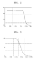
- FIG. 2 is a waveform showing the frequency response curve of an LC filter optimized to a general speaker having an impedance of 8 ⁇ . As shown in FIG. 2 , the audio frequency band 20 Hz - 20 kHz has output frequency response at a regular level.
- FIG. 3 is a waveform showing the frequency response of an LC filter when an impedance of 1 ⁇ is connected to the LC filter optimized to a general speaker having an impedance of 8 ⁇ .
- the frequency response in a high frequency area of 1 kHz - 20 kHz is degraded. That is, the frequency response in a high frequency area of the LC filter 120 is affected by the impedance of the speakers 130.
- the speaker is not damaged within a short period of time but is slowly damaged over a long period of time. Accordingly, although the user may not notice the deterioration of the sound, the impedance of the speakers 130 is reduced but the output of the digital amplifier 110 is regular, so speakers 130 may occasionally catch fire due to overload.
- Exemplary embodiments of the present invention address the above problems and/or disadvantages and other disadvantages not described above. Also, the present invention is not required to overcome the disadvantages described above, and an exemplary embodiment of the present invention may not overcome any of the problems described above.
- the present invention provides a method and apparatus for sensing the state of a speaker and detecting a malfunctioning speaker.
- a method for detecting a malfunctioning speaker including generating a frequency signal for detecting a speaker abnormality, outputting the frequency signal to the speaker, and feeding back the frequency signal, and detecting a speaker abnormality based on the fed-back frequency signal.
- the frequency signal is a signal having a frequency corresponding to a high frequency in an audio frequency band, or a signal having a higher frequency than the audio frequency band.
- the feeding back comprises differentially amplifying the frequency signal, and filtering a predetermined frequency band of the amplified frequency signal, wherein the predetermined frequency band is a frequency band of the frequency signal.
- the fed-back frequency signal is fed back in an input terminal of the speaker.
- the speaker In the detecting, if the level of the fed-back frequency signal is lower than a reference level, the speaker is determined to be malfunctioning.
- the reference level is an output level corresponding to the frequency band of the frequency signal in the frequency response optimized for the impedance of the speaker.
- the frequency signal is played when turning the power on or off, switching from standby mode to play mode, or performing testing.
- an apparatus including a play unit which generates a frequency signal for detecting a speaker abnormality, and outputs the frequency signal to the speaker, a feedback unit which is connected to an input terminal of the speaker, and feeds back the played frequency signal, and a control unit which detects a speaker abnormality based on the fed-back frequency signal.
- the frequency signal is a signal having a frequency corresponding to a high frequency in an audio frequency band, or a signal having a higher frequency than the audio frequency band.
- the feedback unit comprises a differential amplifying unit which differentially amplifies the frequency signal, and a filter unit which filters a predetermined frequency band of the amplified frequency signal, wherein the predetermined frequency band is a frequency band of the frequency signal.
- the control unit determines that the speaker is malfunctioning if the level of the fed-back frequency signal is lower than a reference level.
- the reference level is an output level corresponding to the frequency band of the frequency signal in the frequency response optimized for the impedance of the speaker.
- the control unit operates the play unit to play the frequency signal when turning power on or off, switching from standby mode to play mode, or performing testing.
- the play unit comprises an amplifying unit which converts the frequency signal into a PWM signal and amplifies the PWM signal, and a low pass filter unit which filters high frequency components of the amplified PWM signal.
- FIG. 4 is a block diagram illustrating an apparatus according to an exemplary embodiment of the present invention.
- the apparatus identifies the state of a speaker 430 when turning on/off the apparatus, switching mode, or testing, and determines whether the state of the speaker 430 is functioning properly or malfunctioning. In this case, the apparatus generates an audio signal having a frequency higher than a particular frequency to detect the state of the speaker 430.
- the apparatus includes a digital amplifier 410, a low pass (LC) filter 420, the speaker 430, a sensor 440, a controller 450, a storage unit 460, and a feedback unit 470.
- LC low pass
- the digital amplifier 410 and the LC filter 420 constitute a play unit for generating an analog audio signal.
- the digital amplifier 410 converts an audio signal into a pulse-width-modulation (PWM) signal and amplifies the signal.
- the LC filter 420 performs LC-filtering of high frequency components of the amplified PWM signal and outputs an analog audio signal to the speaker 430.
- the speaker 430 oscillates an oscillator (not shown) according to the analog audio signal and outputs sound.
- the sensor 440 senses whether abnormalities, such as excessive current, excessive voltage, low voltage, or abnormal temperature, occur in the digital amplifier 410, and notifies the controller 440 of the abnormality if the abnormality is sensed. If the sensor 440 senses the abnormality of the digital amplifier 410, the controller 450 cuts off the power supply to the apparatus.
- abnormalities such as excessive current, excessive voltage, low voltage, or abnormal temperature
- the controller 450 operates the digital amplifier 410 and the LC filter 420 to process a frequency signal stored in the storage unit 460.
- the frequency signal stored in the storage unit 460 may be a signal having a frequency of 10 kHz - 20 kHz which corresponds to a high frequency band in audio frequency band, or may be a signal having a frequency higher than the audio frequency.
- the sampling frequency used in general audio apparatuses is 48 kHz, but it is difficult to play a signal having a frequency higher than the audio frequency band.
- the digital amplifier 410 can perform over-sampling to 96 kHz, a signal having a frequency of 30 kHz - 40 kHz can be also played.
- the digital amplifier 410 converts the frequency audio signal output from the storage unit 460 into a PWM signal, and amplifies and outputs the signal.
- the LC filter 420 filters high frequency components of the amplified PWM signal and outputs an analog audio signal.
- the feedback unit 470 is connected to an input terminal of the speaker 430, and feeds back the signal output from the LC filter 420 to the controller 450.
- the feedback unit 470 includes a differential amplifier 472, and a band pass filter 474.
- the differential amplifier 472 amplifies and outputs the difference of a signal output from the LC filter 420.
- the differential amplifier 472 feeds back two signals output from the LC filter 420 and converts them into a single signal if the digital amplifier 410 is designed in a balanced transformerless (BTL) manner, and outputs the two signals positive (+) and negative (-). Accordingly, if the digital amplifier 410 outputting a single signal is provided, the differential amplifier 472 may not be used.
- the band pass filter 474 filters a particular frequency band of the signal amplified by the differential amplifier 472, and outputs the filtered signal to the control unit 450.
- the particular filtered frequency band is a frequency band of the signal stored in the storage unit 460.
- the band pass filter 474 may be replaced with a high pass filter or a low pass filter.
- the controller 450 determines that the speaker 430 is malfunctioning if the level of the signal output from the band pass filter 474 is lower than a reference level, and determines that the speaker 430 is functioning properly if the level of the signal output from the band pass filter 474 is higher than the reference level.
- the reference level is an output level corresponding to the frequency of the signal stored in the storage unit 460 in the frequency response optimized the impedance of the speaker 430.
- the controller 450 cuts off the power supply. That is, sound is not output from the speaker 430, and the user can thus realize that the speaker is malfunctioning.
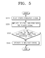
- FIG. 5 is a flow chart illustrating a method for detecting a malfunctioning speaker according to an exemplary embodiment of the present invention.
- the controller 450 operates the digital amplifier 410 and the LC filter 420 to play a frequency signal stored in the storage unit 460.
- the controller 450 identifies the state of the speaker 430 when turning the apparatus on or off, switching from standby mode to play mode, or performing testing.
- the differential amplifier 472 and the band pass filter 474 amplify and filter the signal output from the LC filter 420, and feed back the filtered and amplified signal to the controller 450.
- the controller 450 determines whether the level of the fed-back signal is lower than the reference level. For example, it is assumed that the speaker 430 has an impedance of 8 ⁇ , and the frequency signal stored in the storage unit 460 is 20 kHz. With reference to the frequency response of FIG. 2 , the output level in 20 kHz is 10 V. That is, if the level of the fed-back signal is lower than 10 V, the controller 450 determines that the speaker 430 is malfunctioning.
- the controller 450 determines that the speaker 430 is malfunctioning. In the above embodiment, if the speaker 430 is malfunctioning, the controller 450 cuts off the power supply. However, the controller 450 may be implemented to display "the speaker is malfunctioning" using an on-screen display (OSD).
- OSD on-screen display
- the case of using the digital amplifier is described as an example.
- speaker abnormalities can be detected using a voice coil inside the speaker.
- the frequency signal to detect speaker abnormalities is in an audio frequency band, sound is generated when detecting speaker abnormalities. Accordingly, if an apparatus which plays a melody when the apparatus is turned on/off detects speaker abnormalities when the apparatus is turned on/off, the sound generated to detect speaker abnormalities can be replaced with the melody.
- the apparatus as described above may be adopted in an audio/video (A/V) device for providing users with moving images, or in an audio device for outputting audio using a speaker.
- A/V device is broadcast reception apparatuses such as televisions and set-top boxes, plasma display panels (PDPs), portable multimedia players (PMPs), and the like.
- speaker abnormalities can be easily determined by identifying the state of the speaker whenever particular operations are performed. If the speaker is determined to be abnormal, the power supply is cut off and the danger of a fire starting is thus reduced.
Landscapes
- Physics & Mathematics (AREA)
- Engineering & Computer Science (AREA)
- Acoustics & Sound (AREA)
- Signal Processing (AREA)
- Health & Medical Sciences (AREA)
- General Health & Medical Sciences (AREA)
- Otolaryngology (AREA)
- Circuit For Audible Band Transducer (AREA)
- Amplifiers (AREA)
Abstract
Description
- Apparatuses and methods consistent with the present invention relate to detecting a malfunctioning speaker, and more particularly, to determining whether a speaker is functioning properly or malfunctioning.
- Audio apparatuses process audio signals received from an external source or audio signals stored in recording media, and output sounds corresponding to the audio signals using a speaker. In general, audio apparatuses include a home theater, a television, a radio, a mobile phone and the like.
-
FIG. 1 is a block diagram illustrating a related art audio apparatus. With reference toFIG. 1 , the audio apparatus includes adigital amplifier 110 which converts an audio signal into a pulse-width-modulation (PWM) signal and amplifies the signal, and a low pass (LC)filter 120 which performs LC-filtering high frequency components of the amplified PWM signal and outputs an analog audio signal to one ormore speakers 130. - A
sensor 140 senses the state of thedigital amplifier 110, and acontroller 150 turns off the apparatus if thesensor 140 senses that thedigital amplifier 110 is in an abnormal state, such as excessive current or voltage, low voltage, abnormal temperature, and so on. - The frequency response of the
digital amplifier 110 is determined according to the performance of theLC filter 120, and theLC filter 120 relates to the impedance of thespeakers 130. - In general, the
speakers 130 have an impedance of 4 - 8 Ω, and general home audio apparatuses use speakers having an impedance of 8 Ω. TheLC filter 120 is designed to stabilize the frequency response of an audio frequency band in the impedance of thespeakers 130. -
FIG. 2 is a waveform showing the frequency response curve of an LC filter optimized to a general speaker having an impedance of 8 Ω. As shown inFIG. 2 , the audio frequency band 20 Hz - 20 kHz has output frequency response at a regular level. -
FIG. 3 is a waveform showing the frequency response of an LC filter when an impedance of 1 Ω is connected to the LC filter optimized to a general speaker having an impedance of 8 Ω. InFIG. 3 , the frequency response in a high frequency area of 1 kHz - 20 kHz is degraded. That is, the frequency response in a high frequency area of theLC filter 120 is affected by the impedance of thespeakers 130. - In the related art audio apparatus, there is a method for preventing damage to the
digital amplifier 110 by thesensor 140 sensing abnormalities in thedigital amplifier 110. However, there is no method for protecting thespeaker 130, which is more expensive than thedigital amplifier 110. - For example, if the output of the
digital amplifier 110 exceeds the rating, or a DC level is output, the speaker is not damaged within a short period of time but is slowly damaged over a long period of time. Accordingly, although the user may not notice the deterioration of the sound, the impedance of thespeakers 130 is reduced but the output of thedigital amplifier 110 is regular, sospeakers 130 may occasionally catch fire due to overload. - Therefore, there is a need for methods to sense the state of the
speaker 130. - According to the present invention there is provided an apparatus and method as set forth in the appended claims. Other features of the invention will be apparent from the dependent claims, and the description which follows.
- Exemplary embodiments of the present invention address the above problems and/or disadvantages and other disadvantages not described above. Also, the present invention is not required to overcome the disadvantages described above, and an exemplary embodiment of the present invention may not overcome any of the problems described above.
- The present invention provides a method and apparatus for sensing the state of a speaker and detecting a malfunctioning speaker.
- According to an exemplary aspect of the present invention, there is provided a method for detecting a malfunctioning speaker, the method including generating a frequency signal for detecting a speaker abnormality, outputting the frequency signal to the speaker, and feeding back the frequency signal, and detecting a speaker abnormality based on the fed-back frequency signal.
- The frequency signal is a signal having a frequency corresponding to a high frequency in an audio frequency band, or a signal having a higher frequency than the audio frequency band.
- The feeding back comprises differentially amplifying the frequency signal, and filtering a predetermined frequency band of the amplified frequency signal, wherein the predetermined frequency band is a frequency band of the frequency signal.
- The fed-back frequency signal is fed back in an input terminal of the speaker.
- In the detecting, if the level of the fed-back frequency signal is lower than a reference level, the speaker is determined to be malfunctioning.
- The reference level is an output level corresponding to the frequency band of the frequency signal in the frequency response optimized for the impedance of the speaker.
- The frequency signal is played when turning the power on or off, switching from standby mode to play mode, or performing testing.
- According to an exemplary aspect of the present invention, there is provided an apparatus including a play unit which generates a frequency signal for detecting a speaker abnormality, and outputs the frequency signal to the speaker, a feedback unit which is connected to an input terminal of the speaker, and feeds back the played frequency signal, and a control unit which detects a speaker abnormality based on the fed-back frequency signal.
- The frequency signal is a signal having a frequency corresponding to a high frequency in an audio frequency band, or a signal having a higher frequency than the audio frequency band.
- The feedback unit comprises a differential amplifying unit which differentially amplifies the frequency signal, and a filter unit which filters a predetermined frequency band of the amplified frequency signal, wherein the predetermined frequency band is a frequency band of the frequency signal.
- The control unit determines that the speaker is malfunctioning if the level of the fed-back frequency signal is lower than a reference level.
- The reference level is an output level corresponding to the frequency band of the frequency signal in the frequency response optimized for the impedance of the speaker.
- The control unit operates the play unit to play the frequency signal when turning power on or off, switching from standby mode to play mode, or performing testing.
- The play unit comprises an amplifying unit which converts the frequency signal into a PWM signal and amplifies the PWM signal, and a low pass filter unit which filters high frequency components of the amplified PWM signal.
- The above and/or other aspects of the present invention will be more apparent by describing certain exemplary embodiments of the present invention with reference to the accompanying drawings, in which:
-
FIG. 1 is a block diagram illustrating a general audio apparatus; -
FIG. 2 is a waveform showing the frequency response of an LC filter optimized to a general speaker having an impedance of 8 Ω. -
FIG. 3 is a waveform showing the frequency response of an LC filter when an impedance of 1 Ω is connected to the LC filter optimized to a general speaker having an impedance of 8 Ω; -
FIG. 4 is a block diagram illustrating an apparatus according to an exemplary embodiment of the present invention; and -
FIG. 5 is a flow chart illustrating a method for detecting a malfunctioning speaker according to an exemplary embodiment of the present invention. - Certain exemplary embodiments of the present invention will now be described in greater detail with reference to the accompanying drawings.
- In the following description, same drawing reference numerals are used for the same elements even in different drawings. The matters defined in the description, such as detailed construction and elements, are provided to assist in a comprehensive understanding of the invention. Thus, it is apparent that the present invention can be carried out without those specifically defined matters. Also, well-known functions or constructions are not described in detail since they would obscure the invention with unnecessary detail.
-
FIG. 4 is a block diagram illustrating an apparatus according to an exemplary embodiment of the present invention. - The apparatus identifies the state of a
speaker 430 when turning on/off the apparatus, switching mode, or testing, and determines whether the state of thespeaker 430 is functioning properly or malfunctioning. In this case, the apparatus generates an audio signal having a frequency higher than a particular frequency to detect the state of thespeaker 430. - With reference to
FIG. 4 , the apparatus includes adigital amplifier 410, a low pass (LC)filter 420, thespeaker 430, asensor 440, acontroller 450, astorage unit 460, and afeedback unit 470. - The
digital amplifier 410 and theLC filter 420 constitute a play unit for generating an analog audio signal. In particular, thedigital amplifier 410 converts an audio signal into a pulse-width-modulation (PWM) signal and amplifies the signal. TheLC filter 420 performs LC-filtering of high frequency components of the amplified PWM signal and outputs an analog audio signal to thespeaker 430. - The
speaker 430 oscillates an oscillator (not shown) according to the analog audio signal and outputs sound. - The
sensor 440 senses whether abnormalities, such as excessive current, excessive voltage, low voltage, or abnormal temperature, occur in thedigital amplifier 410, and notifies thecontroller 440 of the abnormality if the abnormality is sensed. If thesensor 440 senses the abnormality of thedigital amplifier 410, thecontroller 450 cuts off the power supply to the apparatus. - In order to detect the state of the
speaker 430, thecontroller 450 operates thedigital amplifier 410 and theLC filter 420 to process a frequency signal stored in thestorage unit 460. The frequency signal stored in thestorage unit 460 may be a signal having a frequency of 10 kHz - 20 kHz which corresponds to a high frequency band in audio frequency band, or may be a signal having a frequency higher than the audio frequency. - The sampling frequency used in general audio apparatuses is 48 kHz, but it is difficult to play a signal having a frequency higher than the audio frequency band. However, as the
digital amplifier 410 can perform over-sampling to 96 kHz, a signal having a frequency of 30 kHz - 40 kHz can be also played. - The
digital amplifier 410 converts the frequency audio signal output from thestorage unit 460 into a PWM signal, and amplifies and outputs the signal. TheLC filter 420 filters high frequency components of the amplified PWM signal and outputs an analog audio signal. - The
feedback unit 470 is connected to an input terminal of thespeaker 430, and feeds back the signal output from theLC filter 420 to thecontroller 450. Thefeedback unit 470 includes adifferential amplifier 472, and aband pass filter 474. - The
differential amplifier 472 amplifies and outputs the difference of a signal output from theLC filter 420. Thedifferential amplifier 472 feeds back two signals output from theLC filter 420 and converts them into a single signal if thedigital amplifier 410 is designed in a balanced transformerless (BTL) manner, and outputs the two signals positive (+) and negative (-). Accordingly, if thedigital amplifier 410 outputting a single signal is provided, thedifferential amplifier 472 may not be used. - The
band pass filter 474 filters a particular frequency band of the signal amplified by thedifferential amplifier 472, and outputs the filtered signal to thecontrol unit 450. The particular filtered frequency band is a frequency band of the signal stored in thestorage unit 460. - If a frequency band used in the apparatus is limited, the
band pass filter 474 may be replaced with a high pass filter or a low pass filter. - The
controller 450 determines that thespeaker 430 is malfunctioning if the level of the signal output from theband pass filter 474 is lower than a reference level, and determines that thespeaker 430 is functioning properly if the level of the signal output from theband pass filter 474 is higher than the reference level. The reference level is an output level corresponding to the frequency of the signal stored in thestorage unit 460 in the frequency response optimized the impedance of thespeaker 430. - If the
speaker 430 is determined to be malfunctioning, thecontroller 450 cuts off the power supply. That is, sound is not output from thespeaker 430, and the user can thus realize that the speaker is malfunctioning. -
FIG. 5 is a flow chart illustrating a method for detecting a malfunctioning speaker according to an exemplary embodiment of the present invention. - With reference to
FIG. 5 , in operation S510, thecontroller 450 operates thedigital amplifier 410 and theLC filter 420 to play a frequency signal stored in thestorage unit 460. Thecontroller 450 identifies the state of thespeaker 430 when turning the apparatus on or off, switching from standby mode to play mode, or performing testing. - In operation S520, the
differential amplifier 472 and theband pass filter 474 amplify and filter the signal output from theLC filter 420, and feed back the filtered and amplified signal to thecontroller 450. - In operation S530, the
controller 450 determines whether the level of the fed-back signal is lower than the reference level. For example, it is assumed that thespeaker 430 has an impedance of 8 Ω, and the frequency signal stored in thestorage unit 460 is 20 kHz. With reference to the frequency response ofFIG. 2 , the output level in 20 kHz is 10 V. That is, if the level of the fed-back signal is lower than 10 V, thecontroller 450 determines that thespeaker 430 is malfunctioning. - In operation S540, if the level of the fed-back signal is determined to be lower than the reference level, the
controller 450 determines that thespeaker 430 is malfunctioning. In the above embodiment, if thespeaker 430 is malfunctioning, thecontroller 450 cuts off the power supply. However, thecontroller 450 may be implemented to display "the speaker is malfunctioning" using an on-screen display (OSD). - Moreover, in the exemplary embodiment, the case of using the digital amplifier is described as an example. However, also in the case that an analog amplifier is used, speaker abnormalities can be detected using a voice coil inside the speaker.
- Furthermore, if the frequency signal to detect speaker abnormalities is in an audio frequency band, sound is generated when detecting speaker abnormalities. Accordingly, if an apparatus which plays a melody when the apparatus is turned on/off detects speaker abnormalities when the apparatus is turned on/off, the sound generated to detect speaker abnormalities can be replaced with the melody.
- The apparatus as described above may be adopted in an audio/video (A/V) device for providing users with moving images, or in an audio device for outputting audio using a speaker. Representative examples of the A/V device are broadcast reception apparatuses such as televisions and set-top boxes, plasma display panels (PDPs), portable multimedia players (PMPs), and the like.
- As can be appreciated from the above description, speaker abnormalities can be easily determined by identifying the state of the speaker whenever particular operations are performed. If the speaker is determined to be abnormal, the power supply is cut off and the danger of a fire starting is thus reduced.
- In addition, as speaker abnormalities can be determined in manufacturing, the possibility of distributing poor speakers in the market place is reduced, resulting in monetary gains and improved image of the manufacturer.
- The foregoing exemplary embodiments and advantages are merely exemplary and are not to be construed as limiting the present invention. The present teachings can be readily applied to other types of apparatuses. Also, the description of the exemplary embodiments of the present invention is intended to be illustrative, and not to limit the scope of the claims, and many alternatives, modifications, and variations will be apparent to those skilled in the art.
- Attention is directed to all papers and documents which are filed concurrently with or previous to this specification in connection with this application and which are open to public inspection with this specification, and the contents of all such papers and documents are incorporated herein by reference.
- All of the features disclosed in this specification (including any accompanying claims, abstract and drawings), and/or all of the steps of any method or process so disclosed, may be combined in any combination, except combinations where at least some of such features and/or steps are mutually exclusive.
- Each feature disclosed in this specification (including any accompanying claims, abstract and drawings) may be replaced by alternative features serving the same, equivalent or similar purpose, unless expressly stated otherwise. Thus, unless expressly stated otherwise, each feature disclosed is one example only of a generic series of equivalent or similar features.
- The invention is not restricted to the details of the foregoing embodiment(s). The invention extends to any novel one, or any novel combination, of the features disclosed in this specification (including any accompanying claims, abstract and drawings), or to any novel one, or any novel combination, of the steps of any method or process so disclosed.
Claims (14)
- A method for detecting a malfunctioning speaker (430), the method comprising:generating a frequency signal for detecting a speaker abnormality;inputting the frequency signal to a speaker (430);feeding back the frequency signal which is input to the speaker (430); anddetecting an abnormality of the speaker (430) based on the fed-back frequency signal.
- The method according to claim 1, wherein the frequency signal is a signal having a frequency corresponding to a high frequency in an audio frequency band, or a signal having a higher frequency than the audio frequency band.
- The method according to any one of claims 1 and 2, wherein the feeding back comprises:differentially amplifying the frequency signal; andfiltering a predetermined frequency band of the amplified frequency signal,wherein the predetermined frequency band is a frequency band of the frequency signal.
- The method according to any one of claims 1 to 3, wherein the fed-back frequency signal is fed back from an input terminal of the speaker (430).
- The method according to any one of claims 1 to 4, wherein in the detecting, if the level of the fed-back frequency signal is lower than a reference level, the speaker (430) is determined to be malfunctioning.
- The method according to claim 5, wherein the reference level is an output level corresponding to a frequency band of the frequency signal in a frequency response optimized for an impedance of the speaker (430).
- The method according to claim 5, wherein the frequency signal is generated if power is turned on or off, switching from a standby mode to a play mode, or performing testing.
- An apparatus comprising:a play unit (410,420) arranged to generate a frequency signal that is output to a speaker (430);a feedback unit (470) which is connected to an input terminal of the speaker (430), and arranged to feed back the frequency signal; anda controller (450) arranged to detect an abnormality of the speaker (430) based on the fed-back frequency signal.
- The apparatus according to claim 8, wherein the frequency signal is a signal having a frequency corresponding to a high frequency in an audio frequency band, or a signal having a higher frequency than the audio frequency band.
- The apparatus according to any one of claims 8 and 9, wherein the feedback unit (470) comprises:a differential amplifier (472) arranged to differentially amplify the frequency signal; anda filter (474) arranged to filter a predetermined frequency band of the amplified frequency signal,wherein the predetermined frequency band is a frequency band of the frequency signal.
- The apparatus according to any one of claims 8 to 10, wherein the control unit is arranged to determine that the speaker (430) is malfunctioning if the level of the fed-back frequency signal is lower than a reference level.
- The apparatus according to claim 11, wherein the reference level is an output level corresponding to a frequency band of the frequency signal in a frequency response optimized for an impedance of the speaker (430).
- The apparatus according to any one of claims 8 to 12, wherein the control unit is arranged to operate the play unit (410,420) to generate the frequency signal if power is turned on or off, switching from a standby mode to a play mode, or performing testing.
- The apparatus according to any one of claims 8 to 13, wherein the play unit (410,420) comprises:an amplifying unit (410) which converts the frequency signal into a pulse-width-modulation (PWM) signal and amplifies the PWM signal; anda low pass filter unit (420) which filters high frequency components of the amplified PWM signal.
Applications Claiming Priority (1)
| Application Number | Priority Date | Filing Date | Title |
|---|---|---|---|
| KR1020070074622A KR101434302B1 (en) | 2007-07-25 | 2007-07-25 | Detection method of defective speaker and sound apparatus using it |
Publications (1)
| Publication Number | Publication Date |
|---|---|
| EP2023670A1 true EP2023670A1 (en) | 2009-02-11 |
Family
ID=39708814
Family Applications (1)
| Application Number | Title | Priority Date | Filing Date |
|---|---|---|---|
| EP08157963A Withdrawn EP2023670A1 (en) | 2007-07-25 | 2008-06-10 | Method and apparatus for detecting malfunctioning speaker |
Country Status (3)
| Country | Link |
|---|---|
| US (1) | US8345886B2 (en) |
| EP (1) | EP2023670A1 (en) |
| KR (1) | KR101434302B1 (en) |
Cited By (2)
| Publication number | Priority date | Publication date | Assignee | Title |
|---|---|---|---|---|
| WO2013079629A1 (en) * | 2011-12-02 | 2013-06-06 | Continental Automotive Gmbh | Method and device for testing a loudspeaker arrangement |
| EP4734556A1 (en) * | 2024-10-25 | 2026-04-29 | Siemens Schweiz AG | Apparatus and method for unobtrusive inspection of an audio device |
Families Citing this family (17)
| Publication number | Priority date | Publication date | Assignee | Title |
|---|---|---|---|---|
| KR101496911B1 (en) * | 2009-03-23 | 2015-02-27 | 삼성전자 주식회사 | Sound test system and method for testing the same |
| DE102009055889B4 (en) * | 2009-11-26 | 2015-02-26 | Austriamicrosystems Ag | Signal processing circuit for generating a loudspeaker signal and signal processing method |
| JP2012023581A (en) * | 2010-07-15 | 2012-02-02 | Hitachi Ltd | Amplifier circuit |
| US8913752B2 (en) * | 2012-03-22 | 2014-12-16 | Htc Corporation | Audio signal measurement method for speaker and electronic apparatus having the speaker |
| US9020623B2 (en) | 2012-06-19 | 2015-04-28 | Sonos, Inc | Methods and apparatus to provide an infrared signal |
| DE102012220137A1 (en) * | 2012-11-06 | 2014-05-08 | Robert Bosch Gmbh | Circuit arrangement and method for testing a microphone and system for operating a microphone with such a circuit arrangement |
| US8989397B2 (en) * | 2013-01-14 | 2015-03-24 | Kyounghee Lee | System and method for high reliability sound production |
| US20140286502A1 (en) * | 2013-03-22 | 2014-09-25 | Htc Corporation | Audio Playback System and Method Used in Handheld Electronic Device |
| KR101855725B1 (en) * | 2014-01-13 | 2018-06-20 | 삼성전자주식회사 | Audio Outputting Control Method and Electronic Device supporting the same |
| CN104657072B (en) * | 2015-01-15 | 2018-06-12 | 小米科技有限责任公司 | It is a kind of to trigger the method and apparatus for performing operational order |
| US9678707B2 (en) | 2015-04-10 | 2017-06-13 | Sonos, Inc. | Identification of audio content facilitated by playback device |
| KR102476306B1 (en) | 2018-03-06 | 2022-12-13 | 삼성전자주식회사 | Electronic device and method for sensing temperature of speaker |
| KR102081971B1 (en) * | 2018-11-13 | 2020-02-26 | 한국항공우주연구원 | Device and method of protecting source for acoustic testing |
| KR102044119B1 (en) * | 2019-04-08 | 2019-11-12 | 정현 | Apparatus and method for detecting disorder of speaker lines in a public address system |
| KR102104101B1 (en) * | 2019-09-19 | 2020-06-01 | 주식회사 디나텍 | Information broadcasting system and method with speaker fault diagnosis function |
| CN111770427B (en) * | 2020-06-24 | 2023-01-24 | 杭州海康威视数字技术股份有限公司 | Microphone array detection method, device, equipment and storage medium |
| KR102619990B1 (en) * | 2023-02-07 | 2023-12-29 | 엘에스전선 주식회사 | System for public address signal distribution with individual speaker path monitoring fuction, and methdo for operating the system |
Citations (4)
| Publication number | Priority date | Publication date | Assignee | Title |
|---|---|---|---|---|
| US4723292A (en) * | 1986-08-27 | 1988-02-02 | Reen Corporation | Voice evacuation system |
| GB2390908A (en) | 2002-07-15 | 2004-01-21 | Visteon Global Tech Inc | Audio loudspeaker detection using back-EMF sensing |
| US20050163326A1 (en) * | 2002-01-17 | 2005-07-28 | Wolfgang Heuer | Diagnostic circuit for a tweeter ina loudspeaker combination |
| US20060126857A1 (en) * | 2004-12-15 | 2006-06-15 | Motorola, Inc. | Speaker diagnostics based upon driving-point impedance |
Family Cites Families (2)
| Publication number | Priority date | Publication date | Assignee | Title |
|---|---|---|---|---|
| JP3296311B2 (en) * | 1998-12-25 | 2002-06-24 | ヤマハ株式会社 | Sound equipment |
| JP2004159244A (en) | 2002-11-08 | 2004-06-03 | Matsushita Electric Ind Co Ltd | Player |
-
2007
- 2007-07-25 KR KR1020070074622A patent/KR101434302B1/en not_active Expired - Fee Related
-
2008
- 2008-01-17 US US12/015,537 patent/US8345886B2/en not_active Expired - Fee Related
- 2008-06-10 EP EP08157963A patent/EP2023670A1/en not_active Withdrawn
Patent Citations (4)
| Publication number | Priority date | Publication date | Assignee | Title |
|---|---|---|---|---|
| US4723292A (en) * | 1986-08-27 | 1988-02-02 | Reen Corporation | Voice evacuation system |
| US20050163326A1 (en) * | 2002-01-17 | 2005-07-28 | Wolfgang Heuer | Diagnostic circuit for a tweeter ina loudspeaker combination |
| GB2390908A (en) | 2002-07-15 | 2004-01-21 | Visteon Global Tech Inc | Audio loudspeaker detection using back-EMF sensing |
| US20060126857A1 (en) * | 2004-12-15 | 2006-06-15 | Motorola, Inc. | Speaker diagnostics based upon driving-point impedance |
Cited By (4)
| Publication number | Priority date | Publication date | Assignee | Title |
|---|---|---|---|---|
| WO2013079629A1 (en) * | 2011-12-02 | 2013-06-06 | Continental Automotive Gmbh | Method and device for testing a loudspeaker arrangement |
| US9277342B2 (en) | 2011-12-02 | 2016-03-01 | Continental Automotive Gmbh | Method and device for testing a loudspeaker arrangement |
| EP4734556A1 (en) * | 2024-10-25 | 2026-04-29 | Siemens Schweiz AG | Apparatus and method for unobtrusive inspection of an audio device |
| WO2026087224A1 (en) * | 2024-10-25 | 2026-04-30 | Siemens Schweiz Ag | Apparatus and method for unobtrusive inspection of an audio device |
Also Published As
| Publication number | Publication date |
|---|---|
| US8345886B2 (en) | 2013-01-01 |
| KR20090011236A (en) | 2009-02-02 |
| KR101434302B1 (en) | 2014-08-27 |
| US20090028349A1 (en) | 2009-01-29 |
Similar Documents
| Publication | Publication Date | Title |
|---|---|---|
| US8345886B2 (en) | Method and apparatus for detecting malfunctioning speaker | |
| US8320587B2 (en) | Audio device and volume adjusting circuit for the audio device | |
| CN102572647B (en) | Sound signal output device, speaker device, and sound signal output method | |
| JP2008294803A (en) | Reproducing device, and reproducing method | |
| US8014539B2 (en) | Method and apparatus to control output power of a digital power amplifier optimized to a headphone and a portable audio player having the same | |
| CN1856188B (en) | Acoustic device, time delay calculation method and recording medium | |
| JP5101957B2 (en) | Electronic volume device and audio equipment using the same | |
| EP2937993B1 (en) | Acoustic processing device | |
| US6240191B1 (en) | Audio volume control circuit using pulse width modulation signal | |
| CN103379400A (en) | Earphone detecting circuit and electronic apparatus having same | |
| CN109462795B (en) | Amplifier, acoustic apparatus, and control method | |
| JP2011139444A (en) | Audio equipment | |
| JP5438483B2 (en) | AMPLIFICATION CIRCUIT, ITS START-UP METHOD, AUDIO REPRODUCTION DEVICE USING THEM, AND ELECTRONIC DEVICE | |
| CN102656904B (en) | Apparatus comprising means for connecting to one or more external loudspeakers and means for detecting such connection | |
| KR101519435B1 (en) | The apparatus for blocking standby power of activespeaker | |
| US8520864B2 (en) | Projector and audio output method | |
| US20060222183A1 (en) | Audio signal amplifying apparatus and distortion correcting method | |
| US20090285411A1 (en) | Audio reproducing apparatus | |
| KR100908306B1 (en) | Multi Audio Mixing Preamplifier | |
| US20020076063A1 (en) | Dynamic allocation of power supplied by a power supply and frequency agile spectral filtering of signals | |
| US8130982B2 (en) | Signal amplifying apparatus, amplification system, and signal amplification method | |
| US20110026728A1 (en) | Audio Output Device | |
| US20240171908A1 (en) | Electronic device with speaker protection mechanism | |
| JP2011139232A (en) | Electric apparatus | |
| JP2006324852A (en) | Input/output switching device |
Legal Events
| Date | Code | Title | Description |
|---|---|---|---|
| PUAI | Public reference made under article 153(3) epc to a published international application that has entered the european phase |
Free format text: ORIGINAL CODE: 0009012 |
|
| AK | Designated contracting states |
Kind code of ref document: A1 Designated state(s): AT BE BG CH CY CZ DE DK EE ES FI FR GB GR HR HU IE IS IT LI LT LU LV MC MT NL NO PL PT RO SE SI SK TR |
|
| AX | Request for extension of the european patent |
Extension state: AL BA MK RS |
|
| 17P | Request for examination filed |
Effective date: 20090714 |
|
| 17Q | First examination report despatched |
Effective date: 20090810 |
|
| AKX | Designation fees paid |
Designated state(s): DE GB NL |
|
| RAP1 | Party data changed (applicant data changed or rights of an application transferred) |
Owner name: SAMSUNG ELECTRONICS CO., LTD. |
|
| STAA | Information on the status of an ep patent application or granted ep patent |
Free format text: STATUS: EXAMINATION IS IN PROGRESS |
|
| STAA | Information on the status of an ep patent application or granted ep patent |
Free format text: STATUS: THE APPLICATION IS DEEMED TO BE WITHDRAWN |
|
| 18D | Application deemed to be withdrawn |
Effective date: 20170103 |