EP2023170A2 - Homogenizing optical beam combiner - Google Patents
Homogenizing optical beam combiner Download PDFInfo
- Publication number
- EP2023170A2 EP2023170A2 EP08075660A EP08075660A EP2023170A2 EP 2023170 A2 EP2023170 A2 EP 2023170A2 EP 08075660 A EP08075660 A EP 08075660A EP 08075660 A EP08075660 A EP 08075660A EP 2023170 A2 EP2023170 A2 EP 2023170A2
- Authority
- EP
- European Patent Office
- Prior art keywords
- leg
- mandrel
- layer
- input
- combining apparatus
- Prior art date
- Legal status (The legal status is an assumption and is not a legal conclusion. Google has not performed a legal analysis and makes no representation as to the accuracy of the status listed.)
- Granted
Links
Images




Classifications
-
- G—PHYSICS
- G02—OPTICS
- G02B—OPTICAL ELEMENTS, SYSTEMS OR APPARATUS
- G02B6/00—Light guides; Structural details of arrangements comprising light guides and other optical elements, e.g. couplings
- G02B6/0001—Light guides; Structural details of arrangements comprising light guides and other optical elements, e.g. couplings specially adapted for lighting devices or systems
- G02B6/0096—Light guides; Structural details of arrangements comprising light guides and other optical elements, e.g. couplings specially adapted for lighting devices or systems the lights guides being of the hollow type
-
- G—PHYSICS
- G02—OPTICS
- G02B—OPTICAL ELEMENTS, SYSTEMS OR APPARATUS
- G02B27/00—Optical systems or apparatus not provided for by any of the groups G02B1/00 - G02B26/00, G02B30/00
- G02B27/09—Beam shaping, e.g. changing the cross-sectional area, not otherwise provided for
- G02B27/0927—Systems for changing the beam intensity distribution, e.g. Gaussian to top-hat
-
- G—PHYSICS
- G02—OPTICS
- G02B—OPTICAL ELEMENTS, SYSTEMS OR APPARATUS
- G02B27/00—Optical systems or apparatus not provided for by any of the groups G02B1/00 - G02B26/00, G02B30/00
- G02B27/09—Beam shaping, e.g. changing the cross-sectional area, not otherwise provided for
- G02B27/0938—Using specific optical elements
- G02B27/0994—Fibers, light pipes
-
- G—PHYSICS
- G02—OPTICS
- G02B—OPTICAL ELEMENTS, SYSTEMS OR APPARATUS
- G02B27/00—Optical systems or apparatus not provided for by any of the groups G02B1/00 - G02B26/00, G02B30/00
- G02B27/10—Beam splitting or combining systems
- G02B27/1006—Beam splitting or combining systems for splitting or combining different wavelengths
-
- G—PHYSICS
- G02—OPTICS
- G02B—OPTICAL ELEMENTS, SYSTEMS OR APPARATUS
- G02B27/00—Optical systems or apparatus not provided for by any of the groups G02B1/00 - G02B26/00, G02B30/00
- G02B27/10—Beam splitting or combining systems
- G02B27/14—Beam splitting or combining systems operating by reflection only
Definitions
- the present disclosure relates generally to optical guides, and more particularly to a homogenizing optical beam combiner.
- Optical devices that combine or homogenize an incoming light beam are known, yet such devices typically include heavy, expensive, and delicate components that may limit the application of these useful techniques.
- Previous attempts have included the use of a hex-shaped glass rod with an exterior cladding configured to provide reflection of light within the glass rod.
- Such a glass rod is typically very expensive to produce, extremely fragile, and has the disadvantage that light may leak out of the glass rod if the exterior cladding is damaged.
- additional components are typically required to produce a uniform intensity distribution.
- Such additional components contribute to the increased cost, weight, and complexity of the optical system since these additional components may be subject to misalignment or may be more susceptible to optical contamination.
- the use of multiple optical elements may lead to substantial intensity losses as a light beam propagates through the multiple optical elements.
- an optical homogenizing and combining apparatus comprises a one piece, hollow, tubular body having a first input leg, a second input leg and an output leg, each leg having a polygonal cross-section and highly reflective interior surfaces.
- the body has a shape corresponding to first and second bent tubes, the tubes being truncated along a plane and joined at a junction lying in the plane.
- a first end of the first tube defines the first input leg
- a first end of the second tube defines the second input leg
- a second end of the first tube and a second end of the second tube define the output leg.
- a method of forming a light combining and homogenizing apparatus comprises forming a mandrel, wherein the mandrel has a shape corresponding to the shape of two symmetrical, bent, truncated polygonal rods joined at a planar truncation face, depositing a body on lateral surfaces of the mandrel, and removing the mandrel from an interior of the body.
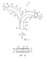
- FIG. 1 shows a side view of a light homogenizing and combining apparatus (LHCA) 100, in accordance with an embodiment of the present invention.
- LHCA 100 may comprise a one-piece, closed, hollow tubular member, or tubular body 102 having legs 104, 112 and 120.
- Each leg 104, 112 and 120 may have a polygonal cross-section, for example hexagonal, and have highly reflective interior surfaces.
- the body 102 may include a first leg 104 or first input leg having an opening 106 configured to receive a first Gaussian light beam 110 of a first intensity and spectral content S1 or color ⁇ 1.
- the light beam 110 is reflected within first leg 104 to provide a first leg output beam 110' ( FIG. 4 ) that is at least partially homogenized.
- body 102 may also include a second leg 112, or second input leg, having an opening 114 configured to receive a second Gaussian light beam 118 of a second intensity and spectral content S2 or color ⁇ 2.
- Light beam 118 may be reflected within second leg 112 to produce a second leg output beam 118' that is at least partially homogenized. While two input legs are shown, this is not considered limiting.
- Body 102 may also include a third leg 120, or output leg with an output opening 124.
- the input legs 104, 112 and the output leg 120 are joined so that substantially all of the energy of the first leg output beam 110' ( FIG. 4 ) and the second leg output beam 118' ( FIG. 4 ) combine at a junction 130, reflect within the third leg 120, resulting in a third leg output beam 126 emitted from the third leg second end 124.
- the third leg output beam 126 may have a third intensity and spectral content S3 or color ⁇ 3 that is a combination of the first intensity and spectral content S1 and the second intensity and spectral content S2.
- the third leg output beam 126 may have a homogenized top hat profile.
- a third leg output beam from a first LHCA 100 may be applied as an input beam to a second LHCA 100, so that three or more Gaussian light beams may be combined in a sequential or serial manner.
- first leg 104, second leg 112, and third leg 120 may each have the same or a different geometrical cross-sections.
- the color of light refers to the wavelength or frequency distribution, band, or spectral content of the light and may include both visible and invisible wavelengths. While a particular spectra or wavelength is described for each beam, it is understood that the color of a beam refers equally to its frequency components and associated intensity for each component, and may also be referred to as frequency profile, spectral content, or spectral power distribution (SPD) for the associated beam.
- SPD spectral power distribution
- the LHCA 100 has a shape corresponding to truncated, bent tubes joined along a junction to define an enclosed LCHA.
- the bent tubes may have a polygonal cross-section, for example hexagonal.
- the tubes may be truncated along a plane parallel with the axis 144 ( FIG. 2 ) of the output leg 124.
- the tubes are truncated such that the edges of one of the bent tubes along the plane of truncation match up with the edges of the other bent tube along the corresponding plane of truncation so that the two truncated, bent tube shapes form a closed LCHA with multiple input openings 106, 112 and an output opening 124 when joined.
- the LCHA 100 may include a plurality of side members 160.
- the side members may include junction side panels 164 and continuous side panels.
- the junction panels 164 have junction edges 165 that all lie in a common plane. The plane is parallel to the axis 144 of the output leg 120.
- the joined junction edges 165 define the junction 130.
- FIG. 2 illustrates a side view of the LHCA 100 of FIG. 1 .
- the opening 106 may be arranged along a central, longitudinal axis 140 normal or perpendicular to the planar cross-section of the opening 106.
- the opening 114 may be arranged along a central, longitudinal axis 142.
- the second end 124 of the third leg 120 may be arranged along a central, longitudinal axis 144.
- the axes 140, 142 may be arranged at angles 151, 152 with respect to the axis 144.
- the angles 151, 152 may be the same angles. In other embodiments, the axes 140, 142 may be at different angles with respect to the axis 144. The angles 151, 152 may be, for example, right angles. In other embodiments, the central, longitudinal axes 140, 142 may be arranged at angles 151, 152 from 90 degrees to 180 degrees up to right angles with respect to the central, longitudinal axis 144.
- the axes 140, 142 may be parallel and co-linear when viewed from a perspective normal to the axis 144, as shown, for example in FIG. 1a .
- the axes 140, 142 may be arranged with an angle 145 from zero to 180 degrees between the axes 140, 142 when viewed from a perspective normal to the axis 144, for example 120 degrees, as shown for example in FIGS. 3 and 3b.
- Fig. 4 illustrates a view of an open cross-section of the LCHA 100 of Fig. 1 .
- the tubular leg portions 104, 112 and 120 of body 102 may have polygonal cross-section shapes. They may also each have a plurality of side members 160 having highly reflective interior surfaces 103, so that light beams reflecting off an interior surface of these planar side members are reflected or folded over at least five times.
- First input leg 104 and output leg 120 define a curved shape for which the geometric center of the polygonal cross-section of the curved shape defines a curve 141.
- Second leg 112 and third leg 120 define a curved shape, where the geometric center of the curved shape defines a curve 143.
- the curves 141 and 143 merge into the same curve at some point before or at the opening 124.
- the distances L1 and L2 may be sufficiently long to permit incoming light beams 110, 118 to reflect off the interior surfaces 103 of the side members 160 and be reflected or folded over at least five times before exiting the opening 124 as output beam 126.
- the distances L1 and L2 may be sufficiently long to permit the incoming light beams 110, 118 to reflect off an interior surface of the side members and be reflected or folded over at least five times, or be nearly completely homogenized, before being combined with each other and to permit the combined light beams to reflect off the interior surfaces of side members of the output leg and be reflected or folded over at least five times again before exiting as output beam 126.
- first and second input beams 110, 118 may have non-homogenized intensity profiles, for example Gaussian profiles.
- First input leg 104 may be configured to receive and reflect the first input light beam 110 to produce at least a partially homogenized beam 110' within the first leg 104 as first input light beam 110 is reflected by the highly reflective interior surfaces 103 of leg 104.
- second input leg 112 may be configured to receive and reflect the second input light beam 118 to produce at least a partially homogenized input beam 118' within the second leg 112.
- the first and second leg output beams 110' and 118' may be combined at a junction portion 130 of the LHCA 100.
- the combined, at least partially homogenized beams 110' and 118' may reflect on the highly reflective interior surfaces 103 of the second leg.
- the third leg 120 may provide an output beam 126 which may be a new single homogenized output beam 126.
- the intensity or amplitude of the output beam may be the sum of the plurality of input beams minus a negligible loss of about 5%.
- the wavelengths (color) of the plurality of input beams are different from each other, then the output beam will have a new, derivative wavelength (color) so LHCA 100 may function as a wavelength blender. In this manner, LHCA 100 performs at least two functions that traditionally may require a minimum of three separate optical components. Therefore, LHCA 100 may provide homogenization and optical combining operations in a more compact, lower weight, and rugged manner while eliminating alignment requirements.
- homogenization includes a process of reflecting light off highly reflective interior surfaces of body 102 a minimum of five times in order to produce an output beam having a top hat profile.
- homogenization includes converting a smaller diameter light beam with a Gaussian intensity distribution into a larger diameter light beam with a top hat intensity distribution.
- Gaussian refers generally to a normal or bell-shaped spatial intensity distribution characterized by a location of higher intensity near the center of a region or cross-section that may fall off uniformly towards the sides of the region.
- the mode of the Gaussian curve corresponds to the center part of the input light beam.
- top hat, or top hat distribution refers to a substantially equal spatial intensity distribution along the region or cross-section in a direction perpendicular to the output beam path.
- the input light source may be composed of wavelengths corresponding to one specific color, a plurality of specific colors, or may comprise white light.
- a desired combination of efficiency and beam quality may be achieved when the lengths L1 and L2 along the curves 141, 143 from the openings 106, 114, respectively, relate to the width W (see FIG. 6 ) of each leg 104, 112 and 120 with a ratio of approximately 6:1 (L:W).
- the efficiency of the beam combining may be at a desirable efficiency, for example optimal homogenization at minimal cost.
- the desired or optimal efficiency may occur where a top hat profile is uniform to within excess of 98 percent of the optimum design. Stated differently, the measured intensity difference across the homogenized output beam may be uniform to within 2%.
- a range of L:W of about 5:1 to about 7:1 may also be acceptable.
- a designer may determine acceptable or desirable parameters for a given application.
- the width W may be in a range from about 4-6 mm or about one quarter of an inch.
- the lengths L1, L2 may be in a range from about 20-42 mm or about one and a half inches.
- Light sources 510, 511 emit or conduct the input light beams 110, 118 having a Gaussian intensity distribution 218 ( FIG. 5 ) and applied to openings 106, 114 of LHCA 100.
- Light beams 110, 118 may have cone patterns where the light may be applied to a substantially central portion of openings 106, 114 equidistant from each side of openings 106, 114, as illustrated, for example, in FIG. 5 . Referring again to FIG. 4 , light beams 110, 118 may then be applied to the highly reflective interior surfaces 103 of the LHCA 100.
- the lengths L1, L2 may be, for example about 42 mm (millimeters) while the width (or diameter) of the legs 104, 112, 120 may be about 7 mm.
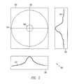
- FIG. 5 shows a graphical intensity depiction 200 including three plane views (202, 204, 206) of an input Gaussian light beam 208, in accordance with an embodiment of the present invention.
- Depiction 200 includes a frontal plane view 202 showing a two-dimensional intensity distribution of an exemplary cross-section of the input Gaussian light beam 208, a profile plane view 204 showing a Gaussian distribution curve 218 depicting the intensity across a central vertical diameter 220 or span, and a horizontal plane view 206 showing a Gaussian distribution curve 222 depicting the intensity across a central horizontal diameter 224 or span.
- a frontal plane view 202 showing a two-dimensional intensity distribution of an exemplary cross-section of the input Gaussian light beam 208
- a profile plane view 204 showing a Gaussian distribution curve 218 depicting the intensity across a central vertical diameter 220 or span
- a horizontal plane view 206 showing a Gaussian distribution curve 222 depicting the intensity across a central horizontal diameter 224 or span
- the light intensity profile varies across the diameter of the optical channel, in a direction perpendicular to the cross section of the channel, with a typical Gaussian intensity distribution.
- the light source may be a single point source such as a fiber optic cable, multiple point sources such as a fiber bundle, or an omni-directional source where only a portion of the emitted light from the source is received by the homogenizing and combining device.
- the wavelength of each light source may be monochromatic or polychromatic, coherent or incoherent.
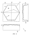
- FIG. 6 shows a graphical intensity depiction 300 including three plane views (302, 304, 306) of an output top hat light beam 308 from a tubular member 310 having a hollow polygonal cross-section 312 and a highly reflective interior surface 314, in accordance with an embodiment of the present invention.
- the polygonal cross-section of tubular member 310 may be a hexagon comprising six, equal-size planar side members, but this is not considered limiting.
- depiction 300 includes a frontal plane view 302 showing an end view of a tubular member having a two-dimensional intensity distribution for an exemplary cross-section of the output top hat light beam 308, a profile plane view 304 showing a top hat distribution curve 318 depicting the intensity across a central vertical diameter 320 or span, and a horizontal plane view 306 showing a top hat distribution curve 322 depicting the intensity across a central horizontal diameter 324 or span of the polygonal cross-section.
- the light intensity profile of output light beam 308 does not substantially vary across the diameter of the optical channel, in a direction perpendicular to the cross section of the channel, with a typical top hat intensity profile or distribution.
- the top hat intensity profile may be provided for all homogenized output light beams. This conversion to a top hat profile is important especially when LHCA 100 ( FIGS. 1, 4 ) is used to project an output beam 308 (126 in FIGS. 1, 4 ) into a bundle of fibers. The homogenous nature of the output beam will assure that each individual fiber within the bundle will receive the same intensity of light.
- the highly reflective interior surfaces 314 of tubular member 310 or body 102 may cause a light beam to fold over onto itself numerous times while passing through body 102, thus reshaping the original input Gaussian profile beam into a highly-uniform, homogenous top hat profile beam.
- Input light beams 110, 118 may each be a point source of white light having a wavelength range from about 380nm to 780nm covering the spectrum of visible light.
- a silver reflective surface within tubular body 102 will provide the highest efficiency.
- input light beams (110, 118) may include any light components above and/or below the visible spectrum.
- white light may include a light beam that includes a plurality of wavelengths, and is thereby differentiated from single wavelength light beam having a particular color.
- the reflective surface within a tubular body 102 may be gold. Gold may provide a desired efficiency, for example, where the input light beams are in the infra-red region of the spectrum. Other materials may be used as desired depending on the wavelength of the input/output light.
- the source of input light beams (110, 118) may be any light conductor or light emitter including a light conducting tubular member placed adjacent to or partially within an input end portion opening 106, 114 ( FIGS 1, 4 ), an output end portion of an optical cable such as a fiber-optic cable or bundle placed adjacent to or partially within an input end portion (106, 114), and/or a white light emitter such as an incandescent lamp, a fluorescent lamp, an Organic Light Emitting Diode (OLED), a chemical light source including a flame, the sun, and/or any other source of illumination directed toward, placed adjacent to, or partially within an input end portion (106, 114).
- the insertion distance partially within an input end portion (106, 114) may be up to about twice the diameter of an input light beam (110, 118) through an insertion plane that may be parallel to an outer edge of planar input end portions (106, 114).
- FIG. 7 shows a graphical sum 400 illustrating an exemplary combination of a first input beam 402 and a second input beam 404, where a combined output beam 406 has an intensity that is the sum of the intensities of the input beams (402, 404), according to an embodiment of the present invention.
- the output beam will be of a third wavelength that is a combination of the input wavelengths.
- a homogenized output beam having a third color may be generated (color generator) based on two Gaussian input beams having two different colors.
- Figure 8 illustrates a method 600 of using a light homogenizing and combining apparatus, according to an embodiment of the present invention.
- input light beams 110, 118 ( FIG. 4 ) are received 602, 606 in first and second input legs 104, 112 ( FIG. 4 ), respectively.
- the input light beams 110, 118 may have Gaussian intensity profiles 218, 222 ( FIG. 5 ).
- the light beams 110, 118 may be emitted from a light sources 510, 511 ( FIG. 4 ), for example fiber optic cables, and be applied to input openings 106, 114 ( FIG. 4 ), respectively.
- the input light beams 110, 118 may be reflected within the legs 104, 112 to produce 604, 608 first and second leg output beams 110', 118'.
- the Gaussian first input light beams may be reshaped into at least partially homogenized top hat profile beams after repeated reflections from the inside surfaces of tubular body 102 ( FIG. 4 ).
- the first and second leg output beams 110', 118' may be homogenized, for example completely homogenized in the first and second legs.
- the at least partially homogenized beams 110', 118' may be combined 610 in the output leg 120 ( FIG. 4 ) of the tubular body 102.
- the combined beam may be reflected and homogenized 612 within the output leg 120 to produce a combined homogenized output beam 126 at the output opening 124 ( FIG. 4 ).
- combined homogenized output beam 126 or 406 FIG. 7
- the combined beams may be blended 614 so that the output beam 126 has a new color that is a combination of the wavelengths present in the input beams.
- an exemplary embodiment of the method 600 shows a combination of two Gaussian light sources
- this process may be utilized for three or more input beams, where the transmitted beam from a prior homogenization and combination stage (i.e. a first LHCA 100) may be asserted to a latter homogenization and combination stage (i.e. a second LHCA 100) so that more than two input beams may be homogenized and combined to produce a top hat profile output beam that is a combination of all input beams.
- the overall system will have an efficiency of at least 92.5 percent, for example greater than 93 percent.
- FIG. 9 illustrates an exemplary method 800 of fabricating an LHCA 100.
- a body 102 FIG. 1
- the method may include providing 802 the mandrel.
- the mandrel may be formed from a material onto which a metal which can provide a highly reflective interior surface may be electroplated.
- the mandrel may be formed from material which is metal, for example aluminum.
- the melting point of the material from which the mandrel is formed may have a lower melting point than the metal used to form the body 102.
- the mandrel may be provided 802 or formed by any process of casting, forming, injection molding or tooling to provide a non-metal mandrel 803 with the desired shape to provide a desired shape of the interior surfaces.
- the mandrel may be formed in a die by injection molding.
- the form may be, for example, wax.
- Aluminum may be deposited 804 on the form and the form melted away 806. The resulting aluminum mandrel may be used for fabricating the body of the LCHA.
- FIG. 10 illustrates an overhead view of a bent rod shape 900.
- the bent rod shape has a first end 902, corresponding to an opening of a first or second leg of an LHCA.
- the shape has a second end 904 corresponding to an exit opening of an LHCA.
- the rod shape 900 is bent at a 90 degree angle with an axis 940 of the first end 902 being at about 90 degrees with respect to an axis of the second end.
- the shape may be truncated along any plane that bisects the end portion of the rod shape corresponding to the output beam opening 904.
- Two rod shapes truncated along the plane A, A' may be placed together to form a mandrel corresponding to the LHCA of FIG. 1 .
- the two bent rod shapes truncated along the planes B, B' may be joined together to form the shape of a mandrel corresponding the the LHCA of FIG. 3A with an angle 145 of 120 degrees between the axes 140 and 142 with respect to the axis 144.
- Two bent rod shapes truncated along the plance C, C' may be placed together to form a mandrel corresponding to an LHCA in which the angle 145 is 60 degrees (not shown). For shapes having other polygonal cross-sections, other angles may be achieved.
- the body may be plated 810 onto the mandrel to build up a "stand alone" thickness where the highly reflective interior surface plating surrounding the mandrel is structurally self-supporting.
- plating 810 the body onto the mandrel may include coating 812 the aluminum form or mandrel with a highly reflective layer corresponding to the highly reflective interior surface of an LHCA to be formed.
- the highly reflective layer may include, for example, silver, gold, or other highly reflective plating material.
- the highly reflective layer may then be coated 814 with an outer layer.
- the outer layer may be a stronger material, for example nickel, that may bond with and/or structurally support the highly reflective plating to provide structural rigidity for the body having a highly reflective interior surface.
- the highly reflective layer may be very thin because the majority of structural support for body is provided by an outer plating layer.
- the highly reflective layer may only be a few atomic layers thick while the outer layer may be composed of nickel that may be approximately 0.002-inches thick.
- the thickness of the outer layer may be determined by the properties of the selected material and the rigidity requirements of a particular mission or application. By reducing the thickness of the highly reflective layer, the cost of the manufactured device may be kept low when the highly reflective material layer may be composed of silver, gold, or other precious metal.
- the composition of the highly reflective material depends upon the wavelength of light being reflected within the tubular member being formed.
- the highly reflective material layer is composed of silver to reflect white light with maximum efficiency.
- the mandrel may then be removed 816, for example by melting 818, chemically etching 820, and/or exploiting some other property such as a difference between the thermal coefficients of expansion between the mandrel and the plating in order to remove the mandrel and form body.
- the aluminum form or mandrel may then be chemically melted away leaving the highly reflective, or highly polished, interior surface within body 102.
- light combining and homogenizing apparatuses may solve several problems without the use of any optical or glass elements such as beamsplitters, mirrors and the like.
- the LCHA may convert Gaussian profile input light beams to a highly homogeneous, top hat profile beam. It may combine the intensity of each initial light beam into a new single higher intensity output beam. It may also be used to combine two beams of different wavelengths (colors) into a new single output beam with a totally different wavelength (color).
- the LCHA may act as a wavelength/color generator, enabling the operator to generate a new colored light beam depending strictly upon the wavelength (color) of the two initial light sources.
- a LCHA according to the disclosure may not require initial alignment steps and may therefore be less susceptible to misalignment and possible optical contamination than other approaches.
- An LCHA according to an embodiment of the disclosure may avoid the costs of additional hardware or components of other approaches and may be smaller and more compact. It may also avoid intensity losses that may occur in the multiple optical elements used in other approaches.
Landscapes
- Physics & Mathematics (AREA)
- General Physics & Mathematics (AREA)
- Optics & Photonics (AREA)
- Optical Elements Other Than Lenses (AREA)
- Non-Portable Lighting Devices Or Systems Thereof (AREA)
Abstract
Description
- The present disclosure relates generally to optical guides, and more particularly to a homogenizing optical beam combiner.
- Optical devices that combine or homogenize an incoming light beam are known, yet such devices typically include heavy, expensive, and delicate components that may limit the application of these useful techniques. Previous attempts have included the use of a hex-shaped glass rod with an exterior cladding configured to provide reflection of light within the glass rod. Such a glass rod is typically very expensive to produce, extremely fragile, and has the disadvantage that light may leak out of the glass rod if the exterior cladding is damaged. When an input beam is non-uniform, additional components are typically required to produce a uniform intensity distribution. Such additional components contribute to the increased cost, weight, and complexity of the optical system since these additional components may be subject to misalignment or may be more susceptible to optical contamination. Further, the use of multiple optical elements may lead to substantial intensity losses as a light beam propagates through the multiple optical elements. Thus, there remains a need for an apparatus and method to provide light combining and homogenization in a rugged, compact, and low cost manner.
- Systems and methods are disclosed herein to provide an optical beam combiner. For example, in accordance with an embodiment, an optical homogenizing and combining apparatus, comprises a one piece, hollow, tubular body having a first input leg, a second input leg and an output leg, each leg having a polygonal cross-section and highly reflective interior surfaces. The body has a shape corresponding to first and second bent tubes, the tubes being truncated along a plane and joined at a junction lying in the plane. A first end of the first tube defines the first input leg, a first end of the second tube defines the second input leg, and a second end of the first tube and a second end of the second tube define the output leg.
- In accordance with another embodiment, a method of forming a light combining and homogenizing apparatus comprises forming a mandrel, wherein the mandrel has a shape corresponding to the shape of two symmetrical, bent, truncated polygonal rods joined at a planar truncation face, depositing a body on lateral surfaces of the mandrel, and removing the mandrel from an interior of the body.
- The scope of the disclosure is defined by the claims, which are incorporated into this section by reference. A more complete understanding of embodiments will be afforded to those skilled in the art, as well as a realization of additional advantages thereof, by a consideration of the following detailed description of one or more embodiments. Reference will be made to the appended sheets of drawings that will first be described briefly.
-
-
FIG. 1 illustrates a light homogenizing and combining apparatus, in accordance with an embodiment of the present invention. -
FIG. 1A illustrates an overhead view of the light homogenizing and combining apparatus ofFIG. 1 . -
FIG. 2 illustrates a side view of the light homogenizing and combining apparatus ofFIG. 1 . -
FIG. 3 illustrates a light homogenizing and combining apparatus in accordance with an embodiment of the present invention. -
FIG. 3A illustrates an overhead view of the light homogenizing and combining apparatus ofFIG. 3 . -
FIG. 4 illustrates an open, cross-sectional view of the light homogenizing and combining apparatus ofFIG. 1 . -
FIG. 5 illustrates a graphical intensity depiction including three plane views of an input Gaussian light beam, in accordance with an embodiment. -
FIG. 6 illustrates a graphical intensity depiction including three plane views of an output top hat light beam from a tubular member having a hollow polygonal cross-section and a highly reflective interior surface, in accordance with an embodiment. -
FIG. 7 illustrates a graphical sum illustrating an exemplary combination of a first input beam and a second input beam, where a combined output beam has an intensity that is the sum of the intensities of the input beams, in accordance with an embodiment. -
FIG. 8 illustrates an exemplary embodiment of a method of using an exemplary embodiment of a light homogenizing and combining apparatus. -
FIG. 9 illustrates an exemplary embodiment of a method of fabricating a light combining and homogenizing apparatus in accordance with an embodiment of this disclosure. -
FIG. 10 illustrates an overhead view of an exemplary embodiment of a bent polygonal rod shape for used in the fabrication of a light combining and homogenizing apparatus. - Embodiments and their advantages are best understood by referring to the detailed description that follows. It should be appreciated that like reference numerals are used to identify like elements illustrated in one or more of the figures.
-
FIG. 1 shows a side view of a light homogenizing and combining apparatus (LHCA) 100, in accordance with an embodiment of the present invention. LHCA 100 may comprise a one-piece, closed, hollow tubular member, ortubular body 102 havinglegs leg - The
body 102 may include afirst leg 104 or first input leg having anopening 106 configured to receive a firstGaussian light beam 110 of a first intensity and spectral content S1 or color λ1. Thelight beam 110 is reflected withinfirst leg 104 to provide a first leg output beam 110' (FIG. 4 ) that is at least partially homogenized. - Similarly,
body 102 may also include asecond leg 112, or second input leg, having anopening 114 configured to receive a secondGaussian light beam 118 of a second intensity and spectral content S2 or color λ2.Light beam 118 may be reflected withinsecond leg 112 to produce a second leg output beam 118' that is at least partially homogenized. While two input legs are shown, this is not considered limiting. -
Body 102 may also include athird leg 120, or output leg with anoutput opening 124. Theinput legs output leg 120 are joined so that substantially all of the energy of the first leg output beam 110' (FIG. 4 ) and the second leg output beam 118' (FIG. 4 ) combine at ajunction 130, reflect within thethird leg 120, resulting in a thirdleg output beam 126 emitted from the third legsecond end 124. - The third
leg output beam 126 may have a third intensity and spectral content S3 or color λ3 that is a combination of the first intensity and spectral content S1 and the second intensity and spectral content S2. The thirdleg output beam 126 may have a homogenized top hat profile. In one alternative, a third leg output beam from afirst LHCA 100 may be applied as an input beam to asecond LHCA 100, so that three or more Gaussian light beams may be combined in a sequential or serial manner. - While the LHCA 100 may have a hexagonal cross-section, other geometrical cross-sections may also be used including triangular, square, pentagonal, heptagonal, and octagonal, for example. Further,
first leg 104,second leg 112, andthird leg 120 may each have the same or a different geometrical cross-sections. - In this disclosure, the color of light refers to the wavelength or frequency distribution, band, or spectral content of the light and may include both visible and invisible wavelengths. While a particular spectra or wavelength is described for each beam, it is understood that the color of a beam refers equally to its frequency components and associated intensity for each component, and may also be referred to as frequency profile, spectral content, or spectral power distribution (SPD) for the associated beam.
- In an example embodiment, the
LHCA 100 has a shape corresponding to truncated, bent tubes joined along a junction to define an enclosed LCHA. The bent tubes may have a polygonal cross-section, for example hexagonal. The tubes may be truncated along a plane parallel with the axis 144 (FIG. 2 ) of theoutput leg 124. The tubes are truncated such that the edges of one of the bent tubes along the plane of truncation match up with the edges of the other bent tube along the corresponding plane of truncation so that the two truncated, bent tube shapes form a closed LCHA withmultiple input openings - The LCHA 100 may include a plurality of
side members 160. The side members may includejunction side panels 164 and continuous side panels. Thejunction panels 164 have junction edges 165 that all lie in a common plane. The plane is parallel to theaxis 144 of theoutput leg 120. The joined junction edges 165 define thejunction 130. - First ends of some of the
continuous panels 168 together with first ends of some of thejunction panels 164 to define thefirst input tube 104 and thefirst input opening 106. First ends of othercontinuous panels 168 together with first ends ofother junction panels 164 define thesecond input leg 112 and the second input opening 114. Second ends of all of thecontinuous panels 168 may be joined together to define theoutput leg 120 andoutput opening 124. -
FIG. 2 illustrates a side view of theLHCA 100 ofFIG. 1 . Theopening 106 may be arranged along a central,longitudinal axis 140 normal or perpendicular to the planar cross-section of theopening 106. Theopening 114 may be arranged along a central,longitudinal axis 142. Thesecond end 124 of thethird leg 120 may be arranged along a central,longitudinal axis 144. Theaxes angles 151, 152 with respect to theaxis 144. - In one embodiment, the
angles 151, 152 may be the same angles. In other embodiments, theaxes axis 144. Theangles 151, 152 may be, for example, right angles. In other embodiments, the central,longitudinal axes angles 151, 152 from 90 degrees to 180 degrees up to right angles with respect to the central,longitudinal axis 144. - In one embodiment, the
axes axis 144, as shown, for example inFIG. 1a . In other embodiments, theaxes angle 145 from zero to 180 degrees between theaxes axis 144, for example 120 degrees, as shown for example inFIGS. 3 and 3b. -
Fig. 4 illustrates a view of an open cross-section of theLCHA 100 ofFig. 1 . Thetubular leg portions body 102 may have polygonal cross-section shapes. They may also each have a plurality ofside members 160 having highly reflectiveinterior surfaces 103, so that light beams reflecting off an interior surface of these planar side members are reflected or folded over at least five times. -
First input leg 104 andoutput leg 120 define a curved shape for which the geometric center of the polygonal cross-section of the curved shape defines acurve 141.Second leg 112 andthird leg 120 define a curved shape, where the geometric center of the curved shape defines acurve 143. Thecurves opening 124. - In an example embodiment, there is a distance L1 along the
curve 141 from theopening 106 to theopening 124 and a distance L2 along thecurve 143 from theopening 114 to theopening 124. The distances L1 and L2 may be sufficiently long to permit incominglight beams interior surfaces 103 of theside members 160 and be reflected or folded over at least five times before exiting theopening 124 asoutput beam 126. - In another embodiment, the distances L1 and L2 may be sufficiently long to permit the incoming
light beams output beam 126. - In an example embodiment, the first and second input beams 110, 118 may have non-homogenized intensity profiles, for example Gaussian profiles.
First input leg 104 may be configured to receive and reflect the firstinput light beam 110 to produce at least a partially homogenized beam 110' within thefirst leg 104 as firstinput light beam 110 is reflected by the highly reflectiveinterior surfaces 103 ofleg 104. Similarly,second input leg 112 may be configured to receive and reflect the secondinput light beam 118 to produce at least a partially homogenized input beam 118' within thesecond leg 112. - The first and second leg output beams 110' and 118' may be combined at a
junction portion 130 of theLHCA 100. The combined, at least partially homogenized beams 110' and 118' may reflect on the highly reflectiveinterior surfaces 103 of the second leg. Thethird leg 120 may provide anoutput beam 126 which may be a new singlehomogenized output beam 126. The intensity or amplitude of the output beam may be the sum of the plurality of input beams minus a negligible loss of about 5%. In addition, if the wavelengths (color) of the plurality of input beams are different from each other, then the output beam will have a new, derivative wavelength (color) soLHCA 100 may function as a wavelength blender. In this manner,LHCA 100 performs at least two functions that traditionally may require a minimum of three separate optical components. Therefore,LHCA 100 may provide homogenization and optical combining operations in a more compact, lower weight, and rugged manner while eliminating alignment requirements. - As used in this disclosure, homogenization includes a process of reflecting light off highly reflective interior surfaces of body 102 a minimum of five times in order to produce an output beam having a top hat profile. In one example, homogenization includes converting a smaller diameter light beam with a Gaussian intensity distribution into a larger diameter light beam with a top hat intensity distribution.
- The term Gaussian, or the phrase Gaussian distribution, refers generally to a normal or bell-shaped spatial intensity distribution characterized by a location of higher intensity near the center of a region or cross-section that may fall off uniformly towards the sides of the region. In this case, the mode of the Gaussian curve corresponds to the center part of the input light beam. The phrase top hat, or top hat distribution, refers to a substantially equal spatial intensity distribution along the region or cross-section in a direction perpendicular to the output beam path. Additionally, the input light source may be composed of wavelengths corresponding to one specific color, a plurality of specific colors, or may comprise white light.
- With reference again to
FIG. 4 , in an example embodiment, a desired combination of efficiency and beam quality may be achieved when the lengths L1 and L2 along thecurves openings FIG. 6 ) of eachleg -
Light sources FIG. 5 ) and applied toopenings LHCA 100. Light beams 110, 118 may have cone patterns where the light may be applied to a substantially central portion ofopenings openings FIG. 5 . Referring again toFIG. 4 ,light beams interior surfaces 103 of theLHCA 100. As the applied light beam travels down the lengths L1, L2, they undergo numerous reflections, combine at thejunction 130 and emerge as an output beam having atop hat profile 318, 322 (FIG. 6 ) from anoutput end 124 ofLHCA 100. During each of the reflections within an interior region ofLHCA 100, the beam actually folds over onto itself resulting in the creation of a highly-uniform, homogenous top hat profile. After a minimum of five such reflections, the beam may be considered homogenous. The lengths L1, L2 may be, for example about 42 mm (millimeters) while the width (or diameter) of thelegs -
FIG. 5 shows agraphical intensity depiction 200 including three plane views (202, 204, 206) of an input Gaussianlight beam 208, in accordance with an embodiment of the present invention.Depiction 200 includes afrontal plane view 202 showing a two-dimensional intensity distribution of an exemplary cross-section of the input Gaussianlight beam 208, aprofile plane view 204 showing aGaussian distribution curve 218 depicting the intensity across a centralvertical diameter 220 or span, and ahorizontal plane view 206 showing aGaussian distribution curve 222 depicting the intensity across a centralhorizontal diameter 224 or span. ' - As shown in
FIG. 5 , the light intensity profile varies across the diameter of the optical channel, in a direction perpendicular to the cross section of the channel, with a typical Gaussian intensity distribution. The light source may be a single point source such as a fiber optic cable, multiple point sources such as a fiber bundle, or an omni-directional source where only a portion of the emitted light from the source is received by the homogenizing and combining device. The wavelength of each light source may be monochromatic or polychromatic, coherent or incoherent. -
FIG. 6 shows agraphical intensity depiction 300 including three plane views (302, 304, 306) of an output tophat light beam 308 from atubular member 310 having a hollowpolygonal cross-section 312 and a highly reflectiveinterior surface 314, in accordance with an embodiment of the present invention. In this example, the polygonal cross-section oftubular member 310 may be a hexagon comprising six, equal-size planar side members, but this is not considered limiting. Specifically,depiction 300 includes afrontal plane view 302 showing an end view of a tubular member having a two-dimensional intensity distribution for an exemplary cross-section of the output tophat light beam 308, aprofile plane view 304 showing a tophat distribution curve 318 depicting the intensity across a centralvertical diameter 320 or span, and ahorizontal plane view 306 showing a tophat distribution curve 322 depicting the intensity across a central horizontal diameter 324 or span of the polygonal cross-section. - As shown in
FIG. 6 , the light intensity profile ofoutput light beam 308 does not substantially vary across the diameter of the optical channel, in a direction perpendicular to the cross section of the channel, with a typical top hat intensity profile or distribution. The top hat intensity profile may be provided for all homogenized output light beams. This conversion to a top hat profile is important especially when LHCA 100 (FIGS. 1, 4 ) is used to project an output beam 308 (126 inFIGS. 1, 4 ) into a bundle of fibers. The homogenous nature of the output beam will assure that each individual fiber within the bundle will receive the same intensity of light. In this manner, the highly reflectiveinterior surfaces 314 oftubular member 310 or body 102 (FIGS. 1, 4 ) may cause a light beam to fold over onto itself numerous times while passing throughbody 102, thus reshaping the original input Gaussian profile beam into a highly-uniform, homogenous top hat profile beam. - Input light beams 110, 118 (
FIGS. 1, 4 ) may each be a point source of white light having a wavelength range from about 380nm to 780nm covering the spectrum of visible light. For visible light or for white light, a silver reflective surface withintubular body 102 will provide the highest efficiency. Alternatively, input light beams (110, 118) may include any light components above and/or below the visible spectrum. For this disclosure, white light may include a light beam that includes a plurality of wavelengths, and is thereby differentiated from single wavelength light beam having a particular color. In another example embodiment, the reflective surface within atubular body 102 may be gold. Gold may provide a desired efficiency, for example, where the input light beams are in the infra-red region of the spectrum. Other materials may be used as desired depending on the wavelength of the input/output light. - The source of input light beams (110, 118) may be any light conductor or light emitter including a light conducting tubular member placed adjacent to or partially within an input end portion opening 106, 114 (
FIGS 1, 4 ), an output end portion of an optical cable such as a fiber-optic cable or bundle placed adjacent to or partially within an input end portion (106, 114), and/or a white light emitter such as an incandescent lamp, a fluorescent lamp, an Organic Light Emitting Diode (OLED), a chemical light source including a flame, the sun, and/or any other source of illumination directed toward, placed adjacent to, or partially within an input end portion (106, 114). The insertion distance partially within an input end portion (106, 114) may be up to about twice the diameter of an input light beam (110, 118) through an insertion plane that may be parallel to an outer edge of planar input end portions (106, 114). -
FIG. 7 shows agraphical sum 400 illustrating an exemplary combination of afirst input beam 402 and asecond input beam 404, where a combined output beam 406 has an intensity that is the sum of the intensities of the input beams (402, 404), according to an embodiment of the present invention. When the input beams are of different wavelengths (i.e. are of different colors) the output beam will be of a third wavelength that is a combination of the input wavelengths. In this manner, a homogenized output beam having a third color may be generated (color generator) based on two Gaussian input beams having two different colors. -
Figure 8 illustrates amethod 600 of using a light homogenizing and combining apparatus, according to an embodiment of the present invention. In an example embodiment, inputlight beams 110, 118 (FIG. 4 ) are received 602, 606 in first andsecond input legs 104, 112 (FIG. 4 ), respectively. The input light beams 110, 118 may have Gaussian intensity profiles 218, 222 (FIG. 5 ). In an example embodiment, the light beams 110, 118 may be emitted from alight sources 510, 511 (FIG. 4 ), for example fiber optic cables, and be applied to inputopenings 106, 114 (FIG. 4 ), respectively. The input light beams 110, 118 may be reflected within thelegs FIG. 4 ). In an example embodiment, the first and second leg output beams 110', 118' may be homogenized, for example completely homogenized in the first and second legs. - In an example embodiment, the at least partially homogenized beams 110', 118' may be combined 610 in the output leg 120 (
FIG. 4 ) of thetubular body 102. The combined beam may be reflected and homogenized 612 within theoutput leg 120 to produce a combinedhomogenized output beam 126 at the output opening 124 (FIG. 4 ). In this manner, combinedhomogenized output beam 126 or 406 (FIG. 7 ) may have a top hat profile and amplitude that is nearly the sum of the amplitudes of the input beams. Further, when the input beams (110, 118) have different wavelengths, the combined beams may be blended 614 so that theoutput beam 126 has a new color that is a combination of the wavelengths present in the input beams. - Although an exemplary embodiment of the
method 600 shows a combination of two Gaussian light sources, this process may be utilized for three or more input beams, where the transmitted beam from a prior homogenization and combination stage (i.e. a first LHCA 100) may be asserted to a latter homogenization and combination stage (i.e. a second LHCA 100) so that more than two input beams may be homogenized and combined to produce a top hat profile output beam that is a combination of all input beams. In an example embodiment, the overall system will have an efficiency of at least 92.5 percent, for example greater than 93 percent. -
FIG. 9 illustrates anexemplary method 800 of fabricating anLHCA 100. In one embodiment, a body 102 (FIG. 1 ) may be fabricated in an electroplating orelectroforming process 800 using a shaped form or mandrel, the exterior shape of the mandrel corresponding to the shape of interior reflective surfaces of the LHCA to be formed. The method may include providing 802 the mandrel. The mandrel may be formed from a material onto which a metal which can provide a highly reflective interior surface may be electroplated. For example, the mandrel may be formed from material which is metal, for example aluminum. The melting point of the material from which the mandrel is formed may have a lower melting point than the metal used to form thebody 102. - The mandrel may be provided 802 or formed by any process of casting, forming, injection molding or tooling to provide a
non-metal mandrel 803 with the desired shape to provide a desired shape of the interior surfaces. In an example embodiment, the mandrel may be formed in a die by injection molding. The form may be, for example, wax. Aluminum may be deposited 804 on the form and the form melted away 806. The resulting aluminum mandrel may be used for fabricating the body of the LCHA. -
FIG. 10 illustrates an overhead view of abent rod shape 900. The bent rod shape has afirst end 902, corresponding to an opening of a first or second leg of an LHCA. The shape has asecond end 904 corresponding to an exit opening of an LHCA. In the embodiment shown inFIG. 10 , therod shape 900 is bent at a 90 degree angle with anaxis 940 of thefirst end 902 being at about 90 degrees with respect to an axis of the second end. - In an example embodiment, the shape may be truncated along any plane that bisects the end portion of the rod shape corresponding to the
output beam opening 904. Two rod shapes truncated along the plane A, A' may be placed together to form a mandrel corresponding to the LHCA ofFIG. 1 . In an example embodiment, the two bent rod shapes truncated along the planes B, B' may be joined together to form the shape of a mandrel corresponding the the LHCA ofFIG. 3A with anangle 145 of 120 degrees between theaxes axis 144. Two bent rod shapes truncated along the plance C, C' may be placed together to form a mandrel corresponding to an LHCA in which theangle 145 is 60 degrees (not shown). For shapes having other polygonal cross-sections, other angles may be achieved. - Referring again to
FIG. 9 , in an example embodiment, the body may be plated 810 onto the mandrel to build up a "stand alone" thickness where the highly reflective interior surface plating surrounding the mandrel is structurally self-supporting. In one embodiment, plating 810 the body onto the mandrel may include coating 812 the aluminum form or mandrel with a highly reflective layer corresponding to the highly reflective interior surface of an LHCA to be formed. The highly reflective layer may include, for example, silver, gold, or other highly reflective plating material. The highly reflective layer may then be coated 814 with an outer layer. The outer layer may be a stronger material, for example nickel, that may bond with and/or structurally support the highly reflective plating to provide structural rigidity for the body having a highly reflective interior surface. The highly reflective layer may be very thin because the majority of structural support for body is provided by an outer plating layer. - In an exemplary embodiment, the highly reflective layer may only be a few atomic layers thick while the outer layer may be composed of nickel that may be approximately 0.002-inches thick. The thickness of the outer layer may be determined by the properties of the selected material and the rigidity requirements of a particular mission or application. By reducing the thickness of the highly reflective layer, the cost of the manufactured device may be kept low when the highly reflective material layer may be composed of silver, gold, or other precious metal. Generally, the composition of the highly reflective material depends upon the wavelength of light being reflected within the tubular member being formed. In one preferred embodiment, the highly reflective material layer is composed of silver to reflect white light with maximum efficiency.
- The mandrel may then be removed 816, for example by melting 818, chemically etching 820, and/or exploiting some other property such as a difference between the thermal coefficients of expansion between the mandrel and the plating in order to remove the mandrel and form body. Once the outer layer is formed, the aluminum form or mandrel may then be chemically melted away leaving the highly reflective, or highly polished, interior surface within
body 102. - In an example embodiment, light combining and homogenizing apparatuses according to the disclosure may solve several problems without the use of any optical or glass elements such as beamsplitters, mirrors and the like. The LCHA may convert Gaussian profile input light beams to a highly homogeneous, top hat profile beam. It may combine the intensity of each initial light beam into a new single higher intensity output beam. It may also be used to combine two beams of different wavelengths (colors) into a new single output beam with a totally different wavelength (color). In this mode, the LCHA may act as a wavelength/color generator, enabling the operator to generate a new colored light beam depending strictly upon the wavelength (color) of the two initial light sources. A LCHA according to the disclosure may not require initial alignment steps and may therefore be less susceptible to misalignment and possible optical contamination than other approaches. An LCHA according to an embodiment of the disclosure may avoid the costs of additional hardware or components of other approaches and may be smaller and more compact. It may also avoid intensity losses that may occur in the multiple optical elements used in other approaches.
- Embodiments described above illustrate but do not limit the invention. It should also be understood that numerous modifications and variations are possible in accordance with the principles of the present invention. Accordingly, the scope of the invention is defined only by the following claims.
Claims (17)
- An optical homogenizing and combining apparatus, comprising:a one piece, hollow, tubular body having a first input leg, a second input leg and an output leg, each leg having a polygonal cross-section and highly reflective interior surfaces; andwherein the body has a shape corresponding to first and second bent tubes, the tubes being truncated along a plane and joined at a junction lying in the plane, wherein a first end of the first tube defines the first input leg, a first end of the second tube defines the second input leg, and a second end of the first tube and a second end of the second tube define the output leg.
- The optical homogenizing and combining apparatus of claim 1, wherein the body is symmetric with respect to the plane of truncation.
- The optical homogenizing and combining apparatus of claim 1 or 2, wherein the interior surface comprises one of silver or gold.
- The optical homogenizing and combining apparatus of claim 1, 2 or 3, wherein the body comprises an exterior layer to provide structural rigidity.
- The optical homogenizing and combining apparatus of claim 3 or 4, wherein the exterior layer comprises nickel.
- The optical homogenizing and combining apparatus any of claims 1-5, wherein the body comprises an interior surface comprising one of silver or gold and comprises an exterior layer comprising nickel.
- The optical homogenizing and combining apparatus of any of claims 1-6, further comprising a first and second plurality of continuous panels and a first and second plurality of junction panels, wherein;
the first plurality of continuous panels and first plurality of junction panels define the first input leg;
the second plurality of continuous panels and second plurality of junction panels define the second input leg;
the first and second plurality of continuous panels define the output leg. - The optical homogenizing and combining apparatus of claim 6 or 7, wherein the first and second plurality of junction panels comprise edges that defining the junction.
- The optical homogenizing and combining apparatus of any of claims 1-8, wherein the polygonal cross-section has a width W and a curve through an interior of the body from the first input opening to the output opening has a length L1, wherein the ration L1:W is in a range from about five to one to seven to one.
- The optical homogenizing and combining apparatus of claim 8 or 9, wherein the ratio L1:W is about six to one.
- A method of forming a light combining and homogenizing apparatus, comprising:forming a mandrel, wherein the mandrel has a shape corresponding to two symmetrical, bent, truncated polygonal rods joined at a planar truncation face;depositing a body on lateral surfaces of the mandrel; andremoving the mandrel from an interior of the body.
- The method of claim 11, wherein depositing the body on the lateral surfaces of the mandrel comprises depositing a first layer comprising a highly reflective material and then depositing a second layer over the first layer, the second layer being thicker than the first layer.
- The method of claim 12, wherein the first layer comprises at least one of gold or silver and the second layer comprises nickel.
- The method of claim 12 or 13, wherein the first layer has a thickness on the order of a few atomic layers and the second layer has a thickness of about 0.002 inches.
- The method of any of claims 11-14, wherein the mandrel comprises a first material and the body comprises a second material, the first material having a first melting point lower than a second melting point of the second material; and
removing the mandrel comprises and The optical homogenizing and combining apparatus of claim 1, wherein the polygonal cross-section comprises a regular hexagon. - The method of any of claims 11-15, wherein removing the mandrel comprises chemically etching the mandrel.
- The method of any of claims 11-16, wherein depositing a body comprises depositing a first layer comprising highly reflective material and depositing a thicker, second layer to provide structural support to the body and wherein removing the mandrel comprises one of melting or chemically etching the mandrel.
Priority Applications (1)
| Application Number | Priority Date | Filing Date | Title |
|---|---|---|---|
| EP11177356.0A EP2386886B1 (en) | 2007-07-30 | 2008-07-25 | Method of forming a homogenizing optical beam combiner |
Applications Claiming Priority (1)
| Application Number | Priority Date | Filing Date | Title |
|---|---|---|---|
| US11/830,706 US7443591B1 (en) | 2007-02-01 | 2007-07-30 | Homogenizing optical beam combiner |
Related Child Applications (2)
| Application Number | Title | Priority Date | Filing Date |
|---|---|---|---|
| EP11177356.0A Division EP2386886B1 (en) | 2007-07-30 | 2008-07-25 | Method of forming a homogenizing optical beam combiner |
| EP11177356.0 Division-Into | 2011-08-12 |
Publications (3)
| Publication Number | Publication Date |
|---|---|
| EP2023170A2 true EP2023170A2 (en) | 2009-02-11 |
| EP2023170A3 EP2023170A3 (en) | 2009-02-25 |
| EP2023170B1 EP2023170B1 (en) | 2013-02-20 |
Family
ID=39870489
Family Applications (2)
| Application Number | Title | Priority Date | Filing Date |
|---|---|---|---|
| EP11177356.0A Not-in-force EP2386886B1 (en) | 2007-07-30 | 2008-07-25 | Method of forming a homogenizing optical beam combiner |
| EP08075660A Not-in-force EP2023170B1 (en) | 2007-07-30 | 2008-07-25 | Method of combining light beams using a homogenizing optical beam combiner |
Family Applications Before (1)
| Application Number | Title | Priority Date | Filing Date |
|---|---|---|---|
| EP11177356.0A Not-in-force EP2386886B1 (en) | 2007-07-30 | 2008-07-25 | Method of forming a homogenizing optical beam combiner |
Country Status (2)
| Country | Link |
|---|---|
| US (1) | US7443591B1 (en) |
| EP (2) | EP2386886B1 (en) |
Cited By (2)
| Publication number | Priority date | Publication date | Assignee | Title |
|---|---|---|---|---|
| US9777901B2 (en) | 2013-02-07 | 2017-10-03 | Zkw Group Gmbh | Headlight for a motor vehicle and method for distributing light |
| CN113805404A (en) * | 2021-11-17 | 2021-12-17 | 滨州学院 | Uniform lighting device for line scanning photoelectric imaging |
Families Citing this family (8)
| Publication number | Priority date | Publication date | Assignee | Title |
|---|---|---|---|---|
| US20100238661A1 (en) * | 2009-03-20 | 2010-09-23 | Sylvan R. Shemitz Designs Incorporated | Asymmetrical light producing baffle and luminaire inclusive thereof |
| US8439526B2 (en) * | 2009-12-11 | 2013-05-14 | Zinovi Brusilovsky | Variable-color lighting system |
| EP2547504A1 (en) * | 2010-03-16 | 2013-01-23 | Pavlo Semenivskyi | A method and an extrusion device for manufacturing closed - section beam elements |
| US20120140463A1 (en) * | 2010-12-07 | 2012-06-07 | Kinzer David J | Led profile luminaire |
| EP2810113A1 (en) * | 2012-02-01 | 2014-12-10 | Koninklijke Philips N.V. | Method, optical system and lighting arrangement for homogenizing light |
| DE102014018934A1 (en) * | 2014-12-22 | 2016-06-23 | Airbus Defence and Space GmbH | Apparatus for heating a composite with temperature-dependent processing properties and related processes |
| US9778419B1 (en) * | 2016-06-23 | 2017-10-03 | The Boeing Company | Fiber optical system with fiber end face area relationships |
| WO2019109071A1 (en) * | 2017-12-01 | 2019-06-06 | Chroma Technology Corp. | System and method for preparing laser light for microscopy |
Family Cites Families (42)
| Publication number | Priority date | Publication date | Assignee | Title |
|---|---|---|---|---|
| US3825741A (en) | 1973-03-05 | 1974-07-23 | Tinsley Labor Inc | Light source with high efficiency light collection means |
| US4964692A (en) | 1982-07-21 | 1990-10-23 | Smith & Nephew Dyonics, Inc. | Fiber bundle illumination system |
| US4632513A (en) | 1983-05-26 | 1986-12-30 | Gould Inc. | Method of making a polarization-insensitive, evanescent-wave, fused coupler with minimal environmental sensitivity |
| US5054869A (en) | 1990-03-02 | 1991-10-08 | Axiom Analytical, Inc. | Light pipe system having maximum radiation throughput |
| US5054874A (en) | 1990-12-17 | 1991-10-08 | Her Majesty The Queen In Right Of Canada, As Represented By The Minister Of Communications | Coupler fabrication techniques for dissimilar fibers |
| US5375185A (en) | 1993-04-30 | 1994-12-20 | Keptel, Inc. | Apparatus for storing and organizing spliced optical fibers |
| US5625738A (en) | 1994-06-28 | 1997-04-29 | Corning Incorporated | Apparatus for uniformly illuminating a light valve |
| CA2143494C (en) | 1995-02-27 | 2004-09-07 | Takao Tanaka | Light transmitting apparatus |
| FR2732094A1 (en) | 1995-03-22 | 1996-09-27 | Philips Eclairage | LIGHT GENERATOR FOR OPTICAL FIBERS |
| US5553183A (en) | 1995-04-03 | 1996-09-03 | Antec Corp. | Apparatus for and methods of splitting fiber optic signals |
| JP3281507B2 (en) | 1995-04-21 | 2002-05-13 | ブラザー工業株式会社 | Optical scanning device |
| US5828505A (en) | 1996-05-10 | 1998-10-27 | Anvik Corporation | Optical beam-shaper-uniformizer construction |
| US5727108A (en) | 1996-09-30 | 1998-03-10 | Troy Investments, Inc. | High efficiency compound parabolic concentrators and optical fiber powered spot luminaire |
| JP3365237B2 (en) | 1996-12-27 | 2003-01-08 | ミノルタ株式会社 | Light guide holding mechanism |
| JPH1166928A (en) | 1997-08-22 | 1999-03-09 | Bridgestone Corp | Linear luminous body |
| JPH1117969A (en) | 1997-06-23 | 1999-01-22 | Fuji Photo Film Co Ltd | Color correction method |
| US6125228A (en) | 1998-03-04 | 2000-09-26 | Swales Aerospace, Inc. | Apparatus for beam splitting, combining wavelength division multiplexing and demultiplexing |
| JP3539665B2 (en) | 1998-03-05 | 2004-07-07 | 日本電信電話株式会社 | Face area correction method, face area correction apparatus, and recording medium storing face area correction program |
| JP3950553B2 (en) | 1998-06-30 | 2007-08-01 | キヤノン株式会社 | Illumination optical system and exposure apparatus having the same |
| JP3885374B2 (en) | 1998-07-28 | 2007-02-21 | 松下電工株式会社 | Light guide bend structure |
| JP2001186323A (en) | 1999-12-24 | 2001-07-06 | Fuji Photo Film Co Ltd | Identification photograph system and picture on processing method |
| US6366308B1 (en) | 2000-02-16 | 2002-04-02 | Ultratech Stepper, Inc. | Laser thermal processing apparatus and method |
| US6324330B1 (en) | 2000-07-10 | 2001-11-27 | Ultratech Stepper, Inc. | Folded light tunnel apparatus and method |
| US6513937B1 (en) | 2000-09-19 | 2003-02-04 | Rockwell Collins, Inc. | Apparatus and method for integrating light from multiple light sources |
| US7042631B2 (en) * | 2001-01-04 | 2006-05-09 | Coherent Technologies, Inc. | Power scalable optical systems for generating, transporting, and delivering high power, high quality, laser beams |
| US6771870B2 (en) | 2001-03-20 | 2004-08-03 | Eele Laboratories | Components and methods for manufacturing hollow integrators and angle converters |
| GB0108671D0 (en) | 2001-04-06 | 2001-05-30 | Dinan Etsuko | Skin treatment |
| US6792190B2 (en) | 2001-06-01 | 2004-09-14 | Telect, Inc. | High density fiber optic splitter/connector tray system |
| US7567384B2 (en) | 2001-06-08 | 2009-07-28 | Infocus Corporation | Method and apparatus for combining light paths of like-colored light sources |
| US6801701B1 (en) | 2002-11-04 | 2004-10-05 | Litton Systems, Inc. | System for bending polymer or glass optical wave guides |
| EP1418459A1 (en) | 2002-11-08 | 2004-05-12 | 3M Innovative Properties Company | Optical device comprising cubo-octahedral polyhedron as light flux splitter or light diffusing element |
| US6986591B2 (en) | 2002-12-20 | 2006-01-17 | Hewlett-Packard Development Company, L.P. | Non-imaging photon concentrator |
| WO2005030983A2 (en) | 2003-09-26 | 2005-04-07 | Circleamp, Inc. | Amplification of polynucleotides by rolling circle amplification |
| KR20050037085A (en) | 2003-10-17 | 2005-04-21 | 삼성전자주식회사 | Light tunnel, illuminating device and projector adopting the same |
| US20050135766A1 (en) * | 2003-12-23 | 2005-06-23 | The Boeing Company | Hex tube light homogenizer system and method |
| US7195375B2 (en) | 2004-01-28 | 2007-03-27 | Anvik Corporation | Compact, high-efficiency, energy-recycling illumination system |
| US7155106B2 (en) | 2004-05-28 | 2006-12-26 | The Boeing Company | High efficiency multi-spectral optical splitter |
| ATE363758T1 (en) | 2004-05-29 | 2007-06-15 | Trumpf Laser Gmbh & Co Kg | BEAM SHAPING OPTICS AND MODULE FOR A DIODE LASER ARRANGEMENT |
| US7295385B2 (en) * | 2005-05-11 | 2007-11-13 | The Boeing Company | Variable, homogenizing optical splitter apparatus and method |
| US7173775B2 (en) | 2005-05-11 | 2007-02-06 | The Boeing Company | Light mixing homogenizer apparatus and method |
| US7420740B2 (en) | 2005-05-11 | 2008-09-02 | Oc Oerlikon Balzers Ag | Device for combination of light of different wavelengths |
| US7113684B1 (en) * | 2005-06-15 | 2006-09-26 | The Boeing Company | Hex tube light homogenizer splitter |
-
2007
- 2007-07-30 US US11/830,706 patent/US7443591B1/en not_active Expired - Fee Related
-
2008
- 2008-07-25 EP EP11177356.0A patent/EP2386886B1/en not_active Not-in-force
- 2008-07-25 EP EP08075660A patent/EP2023170B1/en not_active Not-in-force
Cited By (3)
| Publication number | Priority date | Publication date | Assignee | Title |
|---|---|---|---|---|
| US9777901B2 (en) | 2013-02-07 | 2017-10-03 | Zkw Group Gmbh | Headlight for a motor vehicle and method for distributing light |
| CN113805404A (en) * | 2021-11-17 | 2021-12-17 | 滨州学院 | Uniform lighting device for line scanning photoelectric imaging |
| CN113805404B (en) * | 2021-11-17 | 2022-02-18 | 滨州学院 | Uniform lighting device for line scanning photoelectric imaging |
Also Published As
| Publication number | Publication date |
|---|---|
| EP2386886B1 (en) | 2014-09-03 |
| EP2386886A1 (en) | 2011-11-16 |
| EP2023170A3 (en) | 2009-02-25 |
| EP2023170B1 (en) | 2013-02-20 |
| US7443591B1 (en) | 2008-10-28 |
| US20080247047A1 (en) | 2008-10-09 |
Similar Documents
| Publication | Publication Date | Title |
|---|---|---|
| EP2023170B1 (en) | Method of combining light beams using a homogenizing optical beam combiner | |
| US7386214B1 (en) | Homogenizing optical beam combiner | |
| US7603017B2 (en) | Multi-color curved multi-light generating apparatus | |
| US7684668B2 (en) | Directional light homogenizer assembly | |
| US7171097B2 (en) | Hex tube light homogenizer splitter | |
| US8926152B2 (en) | Ring light illuminator, beam shaper and method for illumination | |
| JP6467353B2 (en) | Apparatus for homogenizing a laser beam | |
| US8831396B1 (en) | Homogenizing optical fiber apparatus and systems employing the same | |
| WO2021037224A1 (en) | Laser light source and laser light source system | |
| EP3619564B1 (en) | Light system for supplying light | |
| US7414793B2 (en) | White light splitting and homogenizing systems and methods | |
| US20050135766A1 (en) | Hex tube light homogenizer system and method | |
| US7173775B2 (en) | Light mixing homogenizer apparatus and method | |
| US7295385B2 (en) | Variable, homogenizing optical splitter apparatus and method | |
| JP2011221191A (en) | Beam uniformizing device and optical processing device | |
| CN2847319Y (en) | Laser beam equalizer for obtaining large area uniform square flare | |
| CN103760636B (en) | A kind of multi-beam splitter | |
| CA2386952A1 (en) | Radiation power demultiplexer | |
| US20230288630A1 (en) | Multi-core fiber, methods of making and use thereof | |
| US6318885B1 (en) | Method and apparatus for coupling light and producing magnified images using an asymmetrical ellipsoid reflective surface | |
| JP2009158177A (en) | Lighting device | |
| US7428356B1 (en) | Homogenizing polygonal shape inverted “Y” optical beam splitter | |
| JP2005025018A (en) | Photonic crystal fiber | |
| JP4444883B2 (en) | Beam homogenizer, laser processing apparatus and laser processing method | |
| DE102011077382A1 (en) | Coupling element for the coupling of LED to fiber bundles |
Legal Events
| Date | Code | Title | Description |
|---|---|---|---|
| PUAI | Public reference made under article 153(3) epc to a published international application that has entered the european phase |
Free format text: ORIGINAL CODE: 0009012 |
|
| PUAL | Search report despatched |
Free format text: ORIGINAL CODE: 0009013 |
|
| AK | Designated contracting states |
Kind code of ref document: A2 Designated state(s): AT BE BG CH CY CZ DE DK EE ES FI FR GB GR HR HU IE IS IT LI LT LU LV MC MT NL NO PL PT RO SE SI SK TR |
|
| AX | Request for extension of the european patent |
Extension state: AL BA MK RS |
|
| AK | Designated contracting states |
Kind code of ref document: A3 Designated state(s): AT BE BG CH CY CZ DE DK EE ES FI FR GB GR HR HU IE IS IT LI LT LU LV MC MT NL NO PL PT RO SE SI SK TR |
|
| AX | Request for extension of the european patent |
Extension state: AL BA MK RS |
|
| 17P | Request for examination filed |
Effective date: 20090616 |
|
| 17Q | First examination report despatched |
Effective date: 20090715 |
|
| AKX | Designation fees paid |
Designated state(s): AT BE BG CH CY CZ DE DK EE ES FI FR GB GR HR HU IE IS IT LI LT LU LV MC MT NL NO PL PT RO SE SI SK TR |
|
| GRAP | Despatch of communication of intention to grant a patent |
Free format text: ORIGINAL CODE: EPIDOSNIGR1 |
|
| GRAJ | Information related to disapproval of communication of intention to grant by the applicant or resumption of examination proceedings by the epo deleted |
Free format text: ORIGINAL CODE: EPIDOSDIGR1 |
|
| GRAP | Despatch of communication of intention to grant a patent |
Free format text: ORIGINAL CODE: EPIDOSNIGR1 |
|
| RTI1 | Title (correction) |
Free format text: METHOD OF COMBINING LIGHT BEAMS USING A HOMOGENIZING OPTICAL BEAM COMBINER |
|
| GRAJ | Information related to disapproval of communication of intention to grant by the applicant or resumption of examination proceedings by the epo deleted |
Free format text: ORIGINAL CODE: EPIDOSDIGR1 |
|
| GRAS | Grant fee paid |
Free format text: ORIGINAL CODE: EPIDOSNIGR3 |
|
| GRAP | Despatch of communication of intention to grant a patent |
Free format text: ORIGINAL CODE: EPIDOSNIGR1 |
|
| GRAA | (expected) grant |
Free format text: ORIGINAL CODE: 0009210 |
|
| AK | Designated contracting states |
Kind code of ref document: B1 Designated state(s): AT BE BG CH CY CZ DE DK EE ES FI FR GB GR HR HU IE IS IT LI LT LU LV MC MT NL NO PL PT RO SE SI SK TR |
|
| REG | Reference to a national code |
Ref country code: GB Ref legal event code: FG4D |
|
| REG | Reference to a national code |
Ref country code: CH Ref legal event code: EP |
|
| REG | Reference to a national code |
Ref country code: AT Ref legal event code: REF Ref document number: 597772 Country of ref document: AT Kind code of ref document: T Effective date: 20130315 |
|
| REG | Reference to a national code |
Ref country code: IE Ref legal event code: FG4D |
|
| REG | Reference to a national code |
Ref country code: DE Ref legal event code: R096 Ref document number: 602008022252 Country of ref document: DE Effective date: 20130418 |
|
| REG | Reference to a national code |
Ref country code: AT Ref legal event code: MK05 Ref document number: 597772 Country of ref document: AT Kind code of ref document: T Effective date: 20130220 |
|
| REG | Reference to a national code |
Ref country code: NL Ref legal event code: VDEP Effective date: 20130220 |
|
| REG | Reference to a national code |
Ref country code: LT Ref legal event code: MG4D |
|
| PG25 | Lapsed in a contracting state [announced via postgrant information from national office to epo] |
Ref country code: LT Free format text: LAPSE BECAUSE OF FAILURE TO SUBMIT A TRANSLATION OF THE DESCRIPTION OR TO PAY THE FEE WITHIN THE PRESCRIBED TIME-LIMIT Effective date: 20130220 Ref country code: AT Free format text: LAPSE BECAUSE OF FAILURE TO SUBMIT A TRANSLATION OF THE DESCRIPTION OR TO PAY THE FEE WITHIN THE PRESCRIBED TIME-LIMIT Effective date: 20130220 Ref country code: IS Free format text: LAPSE BECAUSE OF FAILURE TO SUBMIT A TRANSLATION OF THE DESCRIPTION OR TO PAY THE FEE WITHIN THE PRESCRIBED TIME-LIMIT Effective date: 20130620 Ref country code: ES Free format text: LAPSE BECAUSE OF FAILURE TO SUBMIT A TRANSLATION OF THE DESCRIPTION OR TO PAY THE FEE WITHIN THE PRESCRIBED TIME-LIMIT Effective date: 20130531 Ref country code: NO Free format text: LAPSE BECAUSE OF FAILURE TO SUBMIT A TRANSLATION OF THE DESCRIPTION OR TO PAY THE FEE WITHIN THE PRESCRIBED TIME-LIMIT Effective date: 20130520 Ref country code: BG Free format text: LAPSE BECAUSE OF FAILURE TO SUBMIT A TRANSLATION OF THE DESCRIPTION OR TO PAY THE FEE WITHIN THE PRESCRIBED TIME-LIMIT Effective date: 20130520 Ref country code: SE Free format text: LAPSE BECAUSE OF FAILURE TO SUBMIT A TRANSLATION OF THE DESCRIPTION OR TO PAY THE FEE WITHIN THE PRESCRIBED TIME-LIMIT Effective date: 20130220 |
|
| PG25 | Lapsed in a contracting state [announced via postgrant information from national office to epo] |
Ref country code: GR Free format text: LAPSE BECAUSE OF FAILURE TO SUBMIT A TRANSLATION OF THE DESCRIPTION OR TO PAY THE FEE WITHIN THE PRESCRIBED TIME-LIMIT Effective date: 20130521 Ref country code: LV Free format text: LAPSE BECAUSE OF FAILURE TO SUBMIT A TRANSLATION OF THE DESCRIPTION OR TO PAY THE FEE WITHIN THE PRESCRIBED TIME-LIMIT Effective date: 20130220 Ref country code: SI Free format text: LAPSE BECAUSE OF FAILURE TO SUBMIT A TRANSLATION OF THE DESCRIPTION OR TO PAY THE FEE WITHIN THE PRESCRIBED TIME-LIMIT Effective date: 20130220 Ref country code: FI Free format text: LAPSE BECAUSE OF FAILURE TO SUBMIT A TRANSLATION OF THE DESCRIPTION OR TO PAY THE FEE WITHIN THE PRESCRIBED TIME-LIMIT Effective date: 20130220 Ref country code: PT Free format text: LAPSE BECAUSE OF FAILURE TO SUBMIT A TRANSLATION OF THE DESCRIPTION OR TO PAY THE FEE WITHIN THE PRESCRIBED TIME-LIMIT Effective date: 20130620 Ref country code: BE Free format text: LAPSE BECAUSE OF FAILURE TO SUBMIT A TRANSLATION OF THE DESCRIPTION OR TO PAY THE FEE WITHIN THE PRESCRIBED TIME-LIMIT Effective date: 20130220 Ref country code: PL Free format text: LAPSE BECAUSE OF FAILURE TO SUBMIT A TRANSLATION OF THE DESCRIPTION OR TO PAY THE FEE WITHIN THE PRESCRIBED TIME-LIMIT Effective date: 20130220 |
|
| PG25 | Lapsed in a contracting state [announced via postgrant information from national office to epo] |
Ref country code: HR Free format text: LAPSE BECAUSE OF FAILURE TO SUBMIT A TRANSLATION OF THE DESCRIPTION OR TO PAY THE FEE WITHIN THE PRESCRIBED TIME-LIMIT Effective date: 20130220 |
|
| PG25 | Lapsed in a contracting state [announced via postgrant information from national office to epo] |
Ref country code: CZ Free format text: LAPSE BECAUSE OF FAILURE TO SUBMIT A TRANSLATION OF THE DESCRIPTION OR TO PAY THE FEE WITHIN THE PRESCRIBED TIME-LIMIT Effective date: 20130220 Ref country code: RO Free format text: LAPSE BECAUSE OF FAILURE TO SUBMIT A TRANSLATION OF THE DESCRIPTION OR TO PAY THE FEE WITHIN THE PRESCRIBED TIME-LIMIT Effective date: 20130220 Ref country code: SK Free format text: LAPSE BECAUSE OF FAILURE TO SUBMIT A TRANSLATION OF THE DESCRIPTION OR TO PAY THE FEE WITHIN THE PRESCRIBED TIME-LIMIT Effective date: 20130220 Ref country code: EE Free format text: LAPSE BECAUSE OF FAILURE TO SUBMIT A TRANSLATION OF THE DESCRIPTION OR TO PAY THE FEE WITHIN THE PRESCRIBED TIME-LIMIT Effective date: 20130220 Ref country code: NL Free format text: LAPSE BECAUSE OF FAILURE TO SUBMIT A TRANSLATION OF THE DESCRIPTION OR TO PAY THE FEE WITHIN THE PRESCRIBED TIME-LIMIT Effective date: 20130220 Ref country code: DK Free format text: LAPSE BECAUSE OF FAILURE TO SUBMIT A TRANSLATION OF THE DESCRIPTION OR TO PAY THE FEE WITHIN THE PRESCRIBED TIME-LIMIT Effective date: 20130220 |
|
| PG25 | Lapsed in a contracting state [announced via postgrant information from national office to epo] |
Ref country code: CY Free format text: LAPSE BECAUSE OF FAILURE TO SUBMIT A TRANSLATION OF THE DESCRIPTION OR TO PAY THE FEE WITHIN THE PRESCRIBED TIME-LIMIT Effective date: 20130220 |
|
| PLBE | No opposition filed within time limit |
Free format text: ORIGINAL CODE: 0009261 |
|
| STAA | Information on the status of an ep patent application or granted ep patent |
Free format text: STATUS: NO OPPOSITION FILED WITHIN TIME LIMIT |
|
| PG25 | Lapsed in a contracting state [announced via postgrant information from national office to epo] |
Ref country code: IT Free format text: LAPSE BECAUSE OF FAILURE TO SUBMIT A TRANSLATION OF THE DESCRIPTION OR TO PAY THE FEE WITHIN THE PRESCRIBED TIME-LIMIT Effective date: 20130220 |
|
| 26N | No opposition filed |
Effective date: 20131121 |
|
| PG25 | Lapsed in a contracting state [announced via postgrant information from national office to epo] |
Ref country code: MC Free format text: LAPSE BECAUSE OF FAILURE TO SUBMIT A TRANSLATION OF THE DESCRIPTION OR TO PAY THE FEE WITHIN THE PRESCRIBED TIME-LIMIT Effective date: 20130220 |
|
| REG | Reference to a national code |
Ref country code: CH Ref legal event code: PL |
|
| REG | Reference to a national code |
Ref country code: DE Ref legal event code: R097 Ref document number: 602008022252 Country of ref document: DE Effective date: 20131121 |
|
| REG | Reference to a national code |
Ref country code: IE Ref legal event code: MM4A |
|
| PG25 | Lapsed in a contracting state [announced via postgrant information from national office to epo] |
Ref country code: CH Free format text: LAPSE BECAUSE OF NON-PAYMENT OF DUE FEES Effective date: 20130731 Ref country code: LI Free format text: LAPSE BECAUSE OF NON-PAYMENT OF DUE FEES Effective date: 20130731 |
|
| PG25 | Lapsed in a contracting state [announced via postgrant information from national office to epo] |
Ref country code: IE Free format text: LAPSE BECAUSE OF NON-PAYMENT OF DUE FEES Effective date: 20130725 |
|
| PG25 | Lapsed in a contracting state [announced via postgrant information from national office to epo] |
Ref country code: TR Free format text: LAPSE BECAUSE OF FAILURE TO SUBMIT A TRANSLATION OF THE DESCRIPTION OR TO PAY THE FEE WITHIN THE PRESCRIBED TIME-LIMIT Effective date: 20130220 Ref country code: MT Free format text: LAPSE BECAUSE OF FAILURE TO SUBMIT A TRANSLATION OF THE DESCRIPTION OR TO PAY THE FEE WITHIN THE PRESCRIBED TIME-LIMIT Effective date: 20130220 |
|
| PG25 | Lapsed in a contracting state [announced via postgrant information from national office to epo] |
Ref country code: HU Free format text: LAPSE BECAUSE OF FAILURE TO SUBMIT A TRANSLATION OF THE DESCRIPTION OR TO PAY THE FEE WITHIN THE PRESCRIBED TIME-LIMIT; INVALID AB INITIO Effective date: 20080725 Ref country code: LU Free format text: LAPSE BECAUSE OF NON-PAYMENT OF DUE FEES Effective date: 20130725 |
|
| REG | Reference to a national code |
Ref country code: FR Ref legal event code: PLFP Year of fee payment: 9 |
|
| REG | Reference to a national code |
Ref country code: FR Ref legal event code: PLFP Year of fee payment: 10 |
|
| REG | Reference to a national code |
Ref country code: FR Ref legal event code: PLFP Year of fee payment: 11 |
|
| PGFP | Annual fee paid to national office [announced via postgrant information from national office to epo] |
Ref country code: DE Payment date: 20190729 Year of fee payment: 12 Ref country code: FR Payment date: 20190726 Year of fee payment: 12 |
|
| PGFP | Annual fee paid to national office [announced via postgrant information from national office to epo] |
Ref country code: GB Payment date: 20190729 Year of fee payment: 12 |
|
| REG | Reference to a national code |
Ref country code: DE Ref legal event code: R119 Ref document number: 602008022252 Country of ref document: DE |
|
| GBPC | Gb: european patent ceased through non-payment of renewal fee |
Effective date: 20200725 |
|
| PG25 | Lapsed in a contracting state [announced via postgrant information from national office to epo] |
Ref country code: FR Free format text: LAPSE BECAUSE OF NON-PAYMENT OF DUE FEES Effective date: 20200731 Ref country code: GB Free format text: LAPSE BECAUSE OF NON-PAYMENT OF DUE FEES Effective date: 20200725 |
|
| PG25 | Lapsed in a contracting state [announced via postgrant information from national office to epo] |
Ref country code: DE Free format text: LAPSE BECAUSE OF NON-PAYMENT OF DUE FEES Effective date: 20210202 |