EP2023030A1 - Piping joint - Google Patents
Piping joint Download PDFInfo
- Publication number
- EP2023030A1 EP2023030A1 EP07743380A EP07743380A EP2023030A1 EP 2023030 A1 EP2023030 A1 EP 2023030A1 EP 07743380 A EP07743380 A EP 07743380A EP 07743380 A EP07743380 A EP 07743380A EP 2023030 A1 EP2023030 A1 EP 2023030A1
- Authority
- EP
- European Patent Office
- Prior art keywords
- pipe
- base
- pipes
- flanges
- pipe connector
- Prior art date
- Legal status (The legal status is an assumption and is not a legal conclusion. Google has not performed a legal analysis and makes no representation as to the accuracy of the status listed.)
- Withdrawn
Links
- 238000003780 insertion Methods 0.000 claims abstract description 24
- 230000037431 insertion Effects 0.000 claims abstract description 24
- 239000003507 refrigerant Substances 0.000 description 44
- 230000000994 depressogenic effect Effects 0.000 description 3
- 238000000034 method Methods 0.000 description 3
- 230000000694 effects Effects 0.000 description 2
- 238000012986 modification Methods 0.000 description 1
- 230000004048 modification Effects 0.000 description 1
- 238000005096 rolling process Methods 0.000 description 1
Images




Classifications
-
- F—MECHANICAL ENGINEERING; LIGHTING; HEATING; WEAPONS; BLASTING
- F16—ENGINEERING ELEMENTS AND UNITS; GENERAL MEASURES FOR PRODUCING AND MAINTAINING EFFECTIVE FUNCTIONING OF MACHINES OR INSTALLATIONS; THERMAL INSULATION IN GENERAL
- F16L—PIPES; JOINTS OR FITTINGS FOR PIPES; SUPPORTS FOR PIPES, CABLES OR PROTECTIVE TUBING; MEANS FOR THERMAL INSULATION IN GENERAL
- F16L39/00—Joints or fittings for double-walled or multi-channel pipes or pipe assemblies
-
- F—MECHANICAL ENGINEERING; LIGHTING; HEATING; WEAPONS; BLASTING
- F16—ENGINEERING ELEMENTS AND UNITS; GENERAL MEASURES FOR PRODUCING AND MAINTAINING EFFECTIVE FUNCTIONING OF MACHINES OR INSTALLATIONS; THERMAL INSULATION IN GENERAL
- F16L—PIPES; JOINTS OR FITTINGS FOR PIPES; SUPPORTS FOR PIPES, CABLES OR PROTECTIVE TUBING; MEANS FOR THERMAL INSULATION IN GENERAL
- F16L17/00—Joints with packing adapted to sealing by fluid pressure
- F16L17/06—Joints with packing adapted to sealing by fluid pressure with sealing rings arranged between the end surfaces of the pipes or flanges or arranged in recesses in the pipe ends or flanges
-
- F—MECHANICAL ENGINEERING; LIGHTING; HEATING; WEAPONS; BLASTING
- F16—ENGINEERING ELEMENTS AND UNITS; GENERAL MEASURES FOR PRODUCING AND MAINTAINING EFFECTIVE FUNCTIONING OF MACHINES OR INSTALLATIONS; THERMAL INSULATION IN GENERAL
- F16L—PIPES; JOINTS OR FITTINGS FOR PIPES; SUPPORTS FOR PIPES, CABLES OR PROTECTIVE TUBING; MEANS FOR THERMAL INSULATION IN GENERAL
- F16L23/00—Flanged joints
-
- F—MECHANICAL ENGINEERING; LIGHTING; HEATING; WEAPONS; BLASTING
- F16—ENGINEERING ELEMENTS AND UNITS; GENERAL MEASURES FOR PRODUCING AND MAINTAINING EFFECTIVE FUNCTIONING OF MACHINES OR INSTALLATIONS; THERMAL INSULATION IN GENERAL
- F16L—PIPES; JOINTS OR FITTINGS FOR PIPES; SUPPORTS FOR PIPES, CABLES OR PROTECTIVE TUBING; MEANS FOR THERMAL INSULATION IN GENERAL
- F16L41/00—Branching pipes; Joining pipes to walls
- F16L41/08—Joining pipes to walls or pipes, the joined pipe axis being perpendicular to the plane of a wall or to the axis of another pipe
- F16L41/086—Joining pipes to walls or pipes, the joined pipe axis being perpendicular to the plane of a wall or to the axis of another pipe fixed with screws
-
- F—MECHANICAL ENGINEERING; LIGHTING; HEATING; WEAPONS; BLASTING
- F28—HEAT EXCHANGE IN GENERAL
- F28F—DETAILS OF HEAT-EXCHANGE AND HEAT-TRANSFER APPARATUS, OF GENERAL APPLICATION
- F28F9/00—Casings; Header boxes; Auxiliary supports for elements; Auxiliary members within casings
- F28F9/001—Casings in the form of plate-like arrangements; Frames enclosing a heat exchange core
- F28F9/002—Casings in the form of plate-like arrangements; Frames enclosing a heat exchange core with fastening means for other structures
-
- F—MECHANICAL ENGINEERING; LIGHTING; HEATING; WEAPONS; BLASTING
- F28—HEAT EXCHANGE IN GENERAL
- F28F—DETAILS OF HEAT-EXCHANGE AND HEAT-TRANSFER APPARATUS, OF GENERAL APPLICATION
- F28F9/00—Casings; Header boxes; Auxiliary supports for elements; Auxiliary members within casings
- F28F9/02—Header boxes; End plates
- F28F9/0246—Arrangements for connecting header boxes with flow lines
-
- F—MECHANICAL ENGINEERING; LIGHTING; HEATING; WEAPONS; BLASTING
- F28—HEAT EXCHANGE IN GENERAL
- F28D—HEAT-EXCHANGE APPARATUS, NOT PROVIDED FOR IN ANOTHER SUBCLASS, IN WHICH THE HEAT-EXCHANGE MEDIA DO NOT COME INTO DIRECT CONTACT
- F28D1/00—Heat-exchange apparatus having stationary conduit assemblies for one heat-exchange medium only, the media being in contact with different sides of the conduit wall, in which the other heat-exchange medium is a large body of fluid, e.g. domestic or motor car radiators
- F28D1/02—Heat-exchange apparatus having stationary conduit assemblies for one heat-exchange medium only, the media being in contact with different sides of the conduit wall, in which the other heat-exchange medium is a large body of fluid, e.g. domestic or motor car radiators with heat-exchange conduits immersed in the body of fluid
- F28D1/03—Heat-exchange apparatus having stationary conduit assemblies for one heat-exchange medium only, the media being in contact with different sides of the conduit wall, in which the other heat-exchange medium is a large body of fluid, e.g. domestic or motor car radiators with heat-exchange conduits immersed in the body of fluid with plate-like or laminated conduits
- F28D1/0308—Heat-exchange apparatus having stationary conduit assemblies for one heat-exchange medium only, the media being in contact with different sides of the conduit wall, in which the other heat-exchange medium is a large body of fluid, e.g. domestic or motor car radiators with heat-exchange conduits immersed in the body of fluid with plate-like or laminated conduits the conduits being formed by paired plates touching each other
- F28D1/0325—Heat-exchange apparatus having stationary conduit assemblies for one heat-exchange medium only, the media being in contact with different sides of the conduit wall, in which the other heat-exchange medium is a large body of fluid, e.g. domestic or motor car radiators with heat-exchange conduits immersed in the body of fluid with plate-like or laminated conduits the conduits being formed by paired plates touching each other the plates having lateral openings therein for circulation of the heat-exchange medium from one conduit to another
- F28D1/0333—Heat-exchange apparatus having stationary conduit assemblies for one heat-exchange medium only, the media being in contact with different sides of the conduit wall, in which the other heat-exchange medium is a large body of fluid, e.g. domestic or motor car radiators with heat-exchange conduits immersed in the body of fluid with plate-like or laminated conduits the conduits being formed by paired plates touching each other the plates having lateral openings therein for circulation of the heat-exchange medium from one conduit to another the plates having integrated connecting members
Definitions
- the present invention relates to a pipe connector.
- a pipe connector is disclosed in Japanese Patent Laid-Open No. H7-269987 (see Fig. 1 ).
- the pipe connector includes a first and second pipes each having a flange and a block-shaped base formed with through holes in which the first and second pipes are inserted and supported.
- the pipes are fixed to the base such that the pipe flanges are abut on one side of the base to place the pipes in position in an axial direction.
- both of the flange of the first pipe and the flange of the second pipe are abut on the one side of the base, so that the flanges are disposed side by side in the same level in the axial direction.
- the flanges are disposed on the same plane. Consequently, the diameters of the flanges limit the minimum distance between the pipes and this limits the miniaturization of the pipe connector.
- the present invention provides a pipe connector, in which a plurality of pipes are inserted and fixed in a base, capable of reducing a distance between the plurality of pipes.
- An aspect of the present invention is a pipe connector including pipes each having a flange at an end portion thereof, and a base formed with insertion portions in which the pipes are inserted and seating surfaces formed at a rim of the insertion portion and contacts on the flanges so as to axially fix the pipes, wherein the seating surfaces of the base are apart from each other by more than a thickness of the flanges in the axial position of the pipes such that the flanges are out of alignment with each other in the axial position.
- Figs. 1 to 5 show a first embodiment of the present invention.
- Fig. 1 is an exploded perspective view of a connection structure connecting a pipe connector and an expansion valve of a heat exchanger according to the first embodiment of the present invention.
- Fig. 2 is an enlarged cross section taken along the B-B line in Fig. 1 .
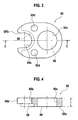
- Fig. 3 is a front view of a base of the pipe connector.
- Fig. 4 is a cross section taken along the C-C line in Fig. 3 .
- Fig. 5 is a cross sectional view showing forming process forming a flange of a refrigerant outlet pipe of the pipe connector, with steps of (a), (b) and (c) in order.
- a pipe connector 60 of this embodiment is to be connected with the expansion valve 50 of an evaporator 1 as a heat exchanger in a refrigerating cycle which works as a counterpart pipe connector 50.
- the pipe connector 60 includes a refrigerant inlet pipe 61 serving as a first pipe which is connected to a heat exchanger inlet 7 via the expansion valve 50, a refrigerant outlet pipe 62 serving as a second pipe which is connected to a heat exchanger outlet 8 via the expansion valve 50, and a base 65 supporting the refrigerant inlet pipe 61 and the refrigerant outlet pipe 62 inserted therein.
- the pipes 61, 62 each have flanges 66, 67 near those end portions.
- the end portions of the pipes 61, 62 serve as pipe connecting parts 61a and 62a to be connected to the counterpart pipe connector.
- the pipe connecting parts 61 a, 62a are configured to be inserted in and connected to a first connecting port 51 and a second connecting port 52 which are formed in the counterpart pipe connector 50, respectively.
- the base 65 is formed in a substantially elliptical shape having a thickness t.
- An insertion portion 65b to which the refrigerant inlet pipe 61 is inserted is formed as a U-shaped opening.
- An insertion portion 65c to which the refrigerant outlet pipe 62 is inserted is formed as a circular hole.
- One side surface 65a of the base 65 which faces the counterpart pipe connector 50, has a first surface 68 and a second seating surface 69 at the periphery of the insertion portions 65b, 65c.
- the first seating surface 68 and the second seating surface 69 are abut on the flanges 66, 67 so as to axially fix the positions of the refrigerant inlet pipe 61 and the refrigerant outlet pipe 62 with respect to the base 65.
- first and second seating surfaces 68, 69 are not aligned in the axial position by at least the thicknesses of the flanges 66, 67. With this configuration, axial positions of the flanges 66 and 67 are relatively shifted from each other.
- the second surface 69 is flash with the one side surface 65a of the base 65 and the first seating surface 68 is depressed from the one side surface 65a of the base by the thickness T1 of the first flange 66 so as to have a gap with the one side surface 65a around the insertion portion 65b.
- the pipe connecting part 61a of the refrigerant inlet pipe 61 which is one end of the refrigerant inlet pipe 61, is formed to have a diameter less than that of the first flange 66.
- the pipe connecting part 61a has an annular groove 61b at the middle thereof to hold an O-ring 70.
- the pipe connecting part 62a which is the end portion of the refrigerant outlet pipe 62, is formed to have the substantially same diameter as that of the flange 67.
- the pipe connecting part 62a has an annular groove 62b at the middle thereof to hold an O-ring 71 that is provided adjacent to the flange 67.
- the end 62a of the refrigerant outlet pipe 62 is formed, firstly, as shown in Fig. 5(a) , the end 62 of the inserted refrigerant outlet pipe 62 is projected from the insertion portion 65c of the base 65 to a predetermined extent; secondly, as shown in Fig. 5(b) , the end 62 which is the projected portion of the refrigerant outlet pipe 62 extending from the insertion portion 65c is expanded in diameter to fit onto an inside of the insertion portion 65c (see the two-dot chain line circle a in the figure); and thirdly, as shown in Fig. 5(c) , the flange 67 and the annular groove 62b are formed by rolling (see the two-dot chain line circle b in the figure).
- the ends 61 a, 62 of the pipes 61, 62 are inserted into the first and second connecting ports 51, 52 of the counterpart pipe connector 50, respectively.
- the first flange 66 of the refrigerant inlet pipe 61 of the pipe connector 60 is abut on the periphery of the first connecting port 51 of the counterpart pipe connector 50
- the flange 67 of the refrigerant outlet pipe 62 of the pipe connector 60 is received within the second connecting port 52 of the counterpart pipe connector 50
- the one side surface 65a of the base 65 is abut on the counterpart pipe connector 50.
- the flanges 66, 67 of the inlet and outlet pipes 61, 62 are abut on the first and second seating surfaces 68, 69 of the base 65 so as to axially fix the flanges 66, 67; however, the first and second seating surfaces 68, 69 are axially away from each other by more than the thickness of the flanges 66, 67 so that the axial position of the flanges 66, 67 is out of alignment with each other.
- the flanges 66, 67 are not overlapped with each other. This allows the refrigerant inlet pipe 61 and the refrigerant outlet pipe 62 to be closer to each other.
- Fig. 6 shows a second embodiment of the present invention.
- the same reference numerals and symbols are used to designate the same elements as the elements described in the first embodiment, and redundant description thereof will be omitted.
- Fig. 6 is a cross sectional view of a pipe connector of the second embodiment.
- the second embodiment has a step portion 72 that is depressed from the other side surface 65e of the base 65 around the insertion portion 65c to which the refrigerant outlet pipe 62 is inserted and the second embodiment has a flange 73 formed at the refrigerant outlet pipe 62 which is provided at a position corresponding to the step portion 72.
- a pipe connector 60A of the second embodiment has similar effects to those of the pipe connector 60 of the first embodiment as well as an effect described below.
- the refrigerant outlet pipe 62 is axially fixed in a manner that a pair of flanges 67, 73 formed on the refrigerant outlet pipe 62 sandwich the base 65 from both side surfaces 65a, 65e thereof, the refrigerant outlet pipe 62 is securely fixed to the base 65.
- Fig. 7 shows a third embodiment of the present invention.
- the same reference numerals and symbols are used to designate the same elements as the elements described in the first embodiment, and redundant description thereof will be omitted.
- Fig. 7 is a cross sectional view of a pipe connector of the third embodiment.
- the insertion portion 65b of the base 65 is formed in a circular hold and the insertion portion 65c in which the refrigerant outlet pipe 62 is inserted is formed in a U-shaped opening.
- first seating surface 68 for fixing the position of the flange 66 is flash with the one side surface 65a of the base 65 and the second seating surface 69 for fixing the position of the flange 67 is depressed from the one side surface 65a of the base by the thickness T2 of the flange 67 so as to have a gap with the one side surface 65a around the insertion portion 65b.
- the other side surface 65e of the base 65 is formed with a recess 74 around the insertion portion 65b in which the refrigerant inlet pipe 61 is inserted, and the refrigerant inlet pipe 61 is formed with a radially outwardly projected flange 75 at a position corresponding to the recess 74 such that the flange 75 is abut on the recess 74.
- the insertion portion 65b in which the refrigerant inlet pipe 61 is inserted is formed as a circular hole and the insertion portion 65c in which the refrigerant outlet pipe 62 is inserted is formed as a U-shaped opening. Therefore, when the refrigerant inlet pipe 61 and the refrigerant outlet pipe 62 are connected to the base 65, the refrigerant inlet pipe 61 is axially inserted into the insertion portion 65b, and the refrigerant outlet pipe 62 is radially put into the insertion portion 65c to be fitted therein.
- the refrigerant inlet pipe 61 is securely fixed to the base 65.
- the present invention has been described above referring to the first to third embodiments, the present invention is not limited to those embodiments. Modifications and variations of the embodiments can be made without departing from the spirit or scope of the present invention.
- the number of the pipes inserted in the base 65 can be more than three, even though the two pipes including the refrigerant inlet pipe 61 and the refrigerant outlet pipe 62 has been described in the above embodiments.
Landscapes
- Engineering & Computer Science (AREA)
- General Engineering & Computer Science (AREA)
- Mechanical Engineering (AREA)
- Physics & Mathematics (AREA)
- Thermal Sciences (AREA)
- Fluid Mechanics (AREA)
- Quick-Acting Or Multi-Walled Pipe Joints (AREA)
Abstract
The pipe connector (60) includes pipes each having a flange at an end portion thereof, and a base (65). The base is formed with insertion portions (65b, 65c) in which the pipes are inserted and seating surfaces (68, 69) formed at a rim of the insertion portion and contacting on the flanges so as to axially fix the pipes. The seating surfaces (68, 69) of the base are apart from each other by more than a thickness of the flanges (66, 67) in the axial position of the pipes (61, 62) such that the axial positions of the flanges are out of alignment with each other.
Description
- The present invention relates to a pipe connector.
- A pipe connector is disclosed in Japanese Patent Laid-Open No.
H7-269987 Fig. 1 ). The pipe connector includes a first and second pipes each having a flange and a block-shaped base formed with through holes in which the first and second pipes are inserted and supported. The pipes are fixed to the base such that the pipe flanges are abut on one side of the base to place the pipes in position in an axial direction. - According the pipe connector, both of the flange of the first pipe and the flange of the second pipe are abut on the one side of the base, so that the flanges are disposed side by side in the same level in the axial direction. In other words, the flanges are disposed on the same plane. Consequently, the diameters of the flanges limit the minimum distance between the pipes and this limits the miniaturization of the pipe connector.
- The present invention provides a pipe connector, in which a plurality of pipes are inserted and fixed in a base, capable of reducing a distance between the plurality of pipes.
- An aspect of the present invention is a pipe connector including pipes each having a flange at an end portion thereof, and a base formed with insertion portions in which the pipes are inserted and seating surfaces formed at a rim of the insertion portion and contacts on the flanges so as to axially fix the pipes, wherein the seating surfaces of the base are apart from each other by more than a thickness of the flanges in the axial position of the pipes such that the flanges are out of alignment with each other in the axial position.
-
- [
Fig. 1] Fig. 1 is an exploded perspective view of a structure for connecting a pipe connector and an expansion valve of a heat exchanger according to a first embodiment of the present invention. - [
Fig. 2] Fig. 2 is an enlarged cross section taken along the B-B line inFig. 1 . - [
Fig. 3] Fig. 3 is a front view of a base of the pipe connector. - [
Fig. 4] Fig. 4 is a cross section taken along the C-C line inFig. 3 . - [
Fig. 5] Fig. 5 is a cross sectional view showing a process for forming a flange of a refrigerant outlet pipe of the pipe connector, with steps (a), (b)and (c) in order. - [
Fig. 6] Fig. 6 is a cross sectional view of a pipe connector according to a second embodiment of the present invention. - [
Fig. 7] Fig. 7 is a cross sectional view of a pipe connector according to a third embodiment of the present invention. - Embodiments of the present invention will be explained in detail.
-
Figs. 1 to 5 show a first embodiment of the present invention.Fig. 1 is an exploded perspective view of a connection structure connecting a pipe connector and an expansion valve of a heat exchanger according to the first embodiment of the present invention.Fig. 2 is an enlarged cross section taken along the B-B line inFig. 1 .Fig. 3 is a front view of a base of the pipe connector.Fig. 4 is a cross section taken along the C-C line inFig. 3 .Fig. 5 is a cross sectional view showing forming process forming a flange of a refrigerant outlet pipe of the pipe connector, with steps of (a), (b) and (c) in order. - A
pipe connector 60 of this embodiment is to be connected with theexpansion valve 50 of an evaporator 1 as a heat exchanger in a refrigerating cycle which works as acounterpart pipe connector 50. - The
pipe connector 60 includes arefrigerant inlet pipe 61 serving as a first pipe which is connected to aheat exchanger inlet 7 via theexpansion valve 50, arefrigerant outlet pipe 62 serving as a second pipe which is connected to a heat exchanger outlet 8 via theexpansion valve 50, and abase 65 supporting therefrigerant inlet pipe 61 and therefrigerant outlet pipe 62 inserted therein. - The
pipes flanges pipes pipe connecting parts pipe connecting parts port 51 and a second connectingport 52 which are formed in thecounterpart pipe connector 50, respectively. - The
base 65, as shown asFigs. 3 and 4 , is formed in a substantially elliptical shape having a thickness t. Aninsertion portion 65b to which therefrigerant inlet pipe 61 is inserted is formed as a U-shaped opening. Aninsertion portion 65c to which therefrigerant outlet pipe 62 is inserted is formed as a circular hole. When therefrigerant inlet pipe 61 and therefrigerant outlet pipe 62 are connected to thebase 65, therefrigerant outlet pipe 62 is inserted into theinsertion portion 65c in the axial direction and therefrigerant inlet pipe 61 is put into theinsertion portion 65b through anopening end 65b' of the U-shaped opening in the radial direction. - One
side surface 65a of thebase 65, which faces thecounterpart pipe connector 50, has afirst surface 68 and asecond seating surface 69 at the periphery of theinsertion portions first seating surface 68 and thesecond seating surface 69 are abut on theflanges refrigerant inlet pipe 61 and therefrigerant outlet pipe 62 with respect to thebase 65. - In this embodiment, the first and
second seating surfaces flanges flanges - More specifically, in this embodiment, the
second surface 69 is flash with the oneside surface 65a of thebase 65 and thefirst seating surface 68 is depressed from the oneside surface 65a of the base by the thickness T1 of thefirst flange 66 so as to have a gap with the oneside surface 65a around theinsertion portion 65b. - The
pipe connecting part 61a of therefrigerant inlet pipe 61, which is one end of therefrigerant inlet pipe 61, is formed to have a diameter less than that of thefirst flange 66. Thepipe connecting part 61a has anannular groove 61b at the middle thereof to hold an O-ring 70. Thepipe connecting part 62a, which is the end portion of therefrigerant outlet pipe 62, is formed to have the substantially same diameter as that of theflange 67. Thepipe connecting part 62a has anannular groove 62b at the middle thereof to hold an O-ring 71 that is provided adjacent to theflange 67. - When the
end 62a of therefrigerant outlet pipe 62 is formed, firstly, as shown inFig. 5(a) , theend 62 of the insertedrefrigerant outlet pipe 62 is projected from theinsertion portion 65c of thebase 65 to a predetermined extent; secondly, as shown inFig. 5(b) , theend 62 which is the projected portion of therefrigerant outlet pipe 62 extending from theinsertion portion 65c is expanded in diameter to fit onto an inside of theinsertion portion 65c (see the two-dot chain line circle a in the figure); and thirdly, as shown inFig. 5(c) , theflange 67 and theannular groove 62b are formed by rolling (see the two-dot chain line circle b in the figure). - Next, a connecting process for connecting the
pipe connector 60 and thecounterpart pipe connector 50 will be explained. - First, the
ends pipes ports counterpart pipe connector 50, respectively. With this, thefirst flange 66 of therefrigerant inlet pipe 61 of thepipe connector 60 is abut on the periphery of the first connectingport 51 of thecounterpart pipe connector 50, theflange 67 of therefrigerant outlet pipe 62 of thepipe connector 60 is received within the second connectingport 52 of thecounterpart pipe connector 50, and the oneside surface 65a of thebase 65 is abut on thecounterpart pipe connector 50. - Next, bolts (not shown) are inserted through an
attachment hole 65d (seeFig. 4 ) formed in thebase 65 and fastened to be fixed to thecounterpart pipe connector 50. With this, theends refrigerant inlet pipe 61 and therefrigerant outlet pipe 62 are prevented from removing out of the first and second connectingports ports counterpart pipe connector 50 and thepipes pipe connector 60 are connected to and communicate with each other. - As described above, according to the
pipe connector 60 of the present embodiment, theflanges outlet pipes second seating surfaces base 65 so as to axially fix theflanges second seating surfaces flanges flanges flanges refrigerant inlet pipe 61 and therefrigerant outlet pipe 62 to be closer to each other. -
Fig. 6 shows a second embodiment of the present invention. In the second embodiment, the same reference numerals and symbols are used to designate the same elements as the elements described in the first embodiment, and redundant description thereof will be omitted.Fig. 6 is a cross sectional view of a pipe connector of the second embodiment. - Differences between the first embodiment and the second embodiment are that the second embodiment has a
step portion 72 that is depressed from theother side surface 65e of thebase 65 around theinsertion portion 65c to which therefrigerant outlet pipe 62 is inserted and the second embodiment has aflange 73 formed at therefrigerant outlet pipe 62 which is provided at a position corresponding to thestep portion 72. - Consequently, a
pipe connector 60A of the second embodiment has similar effects to those of thepipe connector 60 of the first embodiment as well as an effect described below. In the second embodiment, since therefrigerant outlet pipe 62 is axially fixed in a manner that a pair offlanges refrigerant outlet pipe 62 sandwich thebase 65 from bothside surfaces refrigerant outlet pipe 62 is securely fixed to thebase 65. -
Fig. 7 shows a third embodiment of the present invention. In the third embodiment, the same reference numerals and symbols are used to designate the same elements as the elements described in the first embodiment, and redundant description thereof will be omitted.Fig. 7 is a cross sectional view of a pipe connector of the third embodiment. - Contrary to the first embodiment, in the third embodiment, the
insertion portion 65b of thebase 65 is formed in a circular hold and theinsertion portion 65c in which therefrigerant outlet pipe 62 is inserted is formed in a U-shaped opening. - In addition, the
first seating surface 68 for fixing the position of theflange 66 is flash with the oneside surface 65a of thebase 65 and thesecond seating surface 69 for fixing the position of theflange 67 is depressed from the oneside surface 65a of the base by the thickness T2 of theflange 67 so as to have a gap with the oneside surface 65a around theinsertion portion 65b. Moreover, in the third embodiment, theother side surface 65e of thebase 65 is formed with arecess 74 around theinsertion portion 65b in which therefrigerant inlet pipe 61 is inserted, and therefrigerant inlet pipe 61 is formed with a radially outwardly projectedflange 75 at a position corresponding to therecess 74 such that theflange 75 is abut on therecess 74. - According to a
pipe connector 60B of the third embodiment, theinsertion portion 65b in which therefrigerant inlet pipe 61 is inserted is formed as a circular hole and theinsertion portion 65c in which therefrigerant outlet pipe 62 is inserted is formed as a U-shaped opening. Therefore, when therefrigerant inlet pipe 61 and therefrigerant outlet pipe 62 are connected to thebase 65, therefrigerant inlet pipe 61 is axially inserted into theinsertion portion 65b, and therefrigerant outlet pipe 62 is radially put into theinsertion portion 65c to be fitted therein. - Moreover, according to the third embodiment, since two
flanges refrigerant inlet pipe 61 are abut on bothside surfaces base 65, therefrigerant inlet pipe 61 is securely fixed to thebase 65. - Although the present invention has been described above referring to the first to third embodiments, the present invention is not limited to those embodiments. Modifications and variations of the embodiments can be made without departing from the spirit or scope of the present invention. For example, the number of the pipes inserted in the base 65 can be more than three, even though the two pipes including the
refrigerant inlet pipe 61 and therefrigerant outlet pipe 62 has been described in the above embodiments.
Claims (1)
- A pipe connector comprising:pipes each having a flange at an end portion thereof, anda base formed with:insertion portions in which the pipes are inserted, andseating surfaces formed at a rim of the insertion portion and contacting on the flanges so as to axially fix the pipes, the seating surfaces of the base arranged apart from each other by more than a thickness of the flanges in the axial position of the pipes such that the flanges are out of alignment with each other in the axial position.
Applications Claiming Priority (2)
| Application Number | Priority Date | Filing Date | Title |
|---|---|---|---|
| JP2006145485A JP2007315482A (en) | 2006-05-25 | 2006-05-25 | Piping joint |
| PCT/JP2007/059945 WO2007138852A1 (en) | 2006-05-25 | 2007-05-15 | Piping joint |
Publications (1)
| Publication Number | Publication Date |
|---|---|
| EP2023030A1 true EP2023030A1 (en) | 2009-02-11 |
Family
ID=38778372
Family Applications (1)
| Application Number | Title | Priority Date | Filing Date |
|---|---|---|---|
| EP07743380A Withdrawn EP2023030A1 (en) | 2006-05-25 | 2007-05-15 | Piping joint |
Country Status (6)
| Country | Link |
|---|---|
| US (1) | US20090140515A1 (en) |
| EP (1) | EP2023030A1 (en) |
| JP (1) | JP2007315482A (en) |
| KR (1) | KR20090024725A (en) |
| CN (1) | CN101454604A (en) |
| WO (1) | WO2007138852A1 (en) |
Families Citing this family (15)
| Publication number | Priority date | Publication date | Assignee | Title |
|---|---|---|---|---|
| JP5086840B2 (en) * | 2008-02-29 | 2012-11-28 | カルソニックカンセイ株式会社 | Double pipe connection structure and double pipe connection method |
| JP5447975B2 (en) * | 2010-06-29 | 2014-03-19 | 住友電装株式会社 | Gas distribution unit |
| DE102011076800A1 (en) * | 2011-05-31 | 2012-12-06 | Behr Gmbh & Co. Kg | Heat exchanger |
| ES2431468B1 (en) * | 2012-02-21 | 2014-12-10 | Manufactura Moderna De Metales, S.A. | ENGINE FLUID RETURN PIPE AND CRANKCASE INLET |
| WO2014124534A1 (en) | 2013-02-12 | 2014-08-21 | Dana Canada Corporation | Heat exchanger with self-aligning fittings |
| US11028947B2 (en) * | 2013-11-22 | 2021-06-08 | Ford Global Technologies, Llc | Coupling for electric vehicle battery pack |
| DE102014200906A1 (en) * | 2014-01-20 | 2015-07-23 | MAHLE Behr GmbH & Co. KG | Pipe connection, in particular for a heat exchanger |
| EP3331054B1 (en) * | 2015-07-27 | 2024-06-05 | Contemporary Amperex Technology Co., Limited | Battery module heat management assembly |
| EP3296607B1 (en) * | 2016-09-16 | 2019-09-04 | Eaton Corporation | Hose alignment subassemblies |
| CN108346839B (en) * | 2017-01-22 | 2020-01-17 | 宁德时代新能源科技股份有限公司 | battery heat exchange system |
| DE102017215157A1 (en) * | 2017-08-30 | 2019-02-28 | Mahle International Gmbh | connection clamp |
| FR3093357B1 (en) * | 2019-03-01 | 2021-05-14 | Valeo Systemes Thermiques | Thermal regulation device, in particular for cooling, for a motor vehicle |
| US12202446B2 (en) | 2019-09-12 | 2025-01-21 | A. Raymond Et Cie | Flow control valve and system for cleaning a vehicle surface |
| EP4425022A3 (en) | 2019-09-12 | 2025-03-12 | A. Raymond Et Cie | Flow control valve and system for cleaning a vehicle surface |
| DE102024207244A1 (en) * | 2024-07-31 | 2026-02-05 | Zf Friedrichshafen Ag | Arrangement of a gearbox and a heat exchanger of a motor vehicle |
Family Cites Families (27)
| Publication number | Priority date | Publication date | Assignee | Title |
|---|---|---|---|---|
| US2475468A (en) * | 1945-11-02 | 1949-07-05 | M O Valve Co Ltd | Detachable union for cooling systems |
| US3512806A (en) * | 1968-01-22 | 1970-05-19 | Russell H Romney | Adapter for multiple connections to intravenous fluid receptacles and the like |
| US3758138A (en) * | 1971-10-21 | 1973-09-11 | R Roseman | Tube connection for fluid handling apparatus |
| US3944264A (en) * | 1975-01-06 | 1976-03-16 | Westinghouse Air Brake Company | Pipe bracket |
| JPS5454918U (en) * | 1977-09-26 | 1979-04-16 | ||
| JPS5454918A (en) * | 1977-10-11 | 1979-05-01 | Kawasaki Steel Co | Selene recovery from selene containing sludge |
| US4468054A (en) * | 1982-11-03 | 1984-08-28 | The Singer Company | Flange mounted thermostatic expansion valve |
| DE3501679C1 (en) * | 1985-01-19 | 1986-06-05 | Knebel & Röttger GmbH & Co, 5860 Iserlohn | Outlet fitting |
| JPH066886U (en) * | 1992-06-26 | 1994-01-28 | エスエムシー株式会社 | Pipe fitting |
| US5280964A (en) * | 1992-09-10 | 1994-01-25 | Hydro-Craft, Inc. | Junction adapter with axial extension portions |
| FR2697890B1 (en) * | 1992-10-12 | 1994-12-09 | Valeo Thermique Habitacle | Connection flange for motor vehicle air conditioning system. |
| JP3413937B2 (en) * | 1994-03-28 | 2003-06-09 | 株式会社デンソー | Piping connection device |
| JP3281997B2 (en) | 1994-03-31 | 2002-05-13 | 株式会社ゼクセルヴァレオクライメートコントロール | Piping connection connector |
| US5467611A (en) * | 1994-11-07 | 1995-11-21 | General Motors Corporation | Two plate TXV block connector for automotive A/C system with common bolts and independently attachable sides |
| EP0713994B1 (en) * | 1994-11-23 | 2000-09-20 | Automotive Fluid Systems, Inc. | Connecting block with inserts |
| JPH08240288A (en) * | 1995-03-03 | 1996-09-17 | Hitachi Constr Mach Co Ltd | Pipe connection structure and manufacturing method thereof |
| AU1568097A (en) * | 1995-12-22 | 1997-07-17 | Kelsey-Hayes Company | Quick-connect arrangement for high density hydraulic lines for anti-lock brake and/or traction control systems |
| JPH10220660A (en) * | 1997-01-31 | 1998-08-21 | Zexel Corp | Flange joint and method of forming the same |
| JP3593434B2 (en) * | 1997-02-06 | 2004-11-24 | サンデン株式会社 | Heat exchanger unit |
| US6382678B1 (en) * | 1998-10-02 | 2002-05-07 | Parker-Hannifin Corporation | Coupling assembly |
| CN1321232A (en) * | 1998-10-02 | 2001-11-07 | 易通艾罗奎普有限公司 | Coupling assembly |
| DE19902397C1 (en) * | 1999-01-22 | 2000-07-20 | Hansa Metallwerke Ag | Sanitary fitting, in particular wash basin fitting |
| US6776421B2 (en) * | 2000-02-10 | 2004-08-17 | Delphi Technologies, Inc. | Fluid sealing system |
| US6682100B2 (en) * | 2001-02-15 | 2004-01-27 | Parker-Hannifin Corporation | Connection block with clip |
| JP3821064B2 (en) * | 2002-07-01 | 2006-09-13 | 株式会社デンソー | Piping joint structure and manufacturing method thereof |
| JP2004291072A (en) * | 2003-03-28 | 2004-10-21 | Calsonic Kansei Corp | Pipe end processing method and flanged pipe joint manufacturing method |
| US7032500B1 (en) * | 2004-08-27 | 2006-04-25 | Dana Corporation | Single point steering gear hydraulic connection |
-
2006
- 2006-05-25 JP JP2006145485A patent/JP2007315482A/en active Pending
-
2007
- 2007-05-15 KR KR1020087031350A patent/KR20090024725A/en not_active Withdrawn
- 2007-05-15 EP EP07743380A patent/EP2023030A1/en not_active Withdrawn
- 2007-05-15 US US12/302,233 patent/US20090140515A1/en not_active Abandoned
- 2007-05-15 WO PCT/JP2007/059945 patent/WO2007138852A1/en not_active Ceased
- 2007-05-15 CN CNA2007800192211A patent/CN101454604A/en active Pending
Non-Patent Citations (1)
| Title |
|---|
| See references of WO2007138852A1 * |
Also Published As
| Publication number | Publication date |
|---|---|
| KR20090024725A (en) | 2009-03-09 |
| CN101454604A (en) | 2009-06-10 |
| US20090140515A1 (en) | 2009-06-04 |
| JP2007315482A (en) | 2007-12-06 |
| WO2007138852A1 (en) | 2007-12-06 |
Similar Documents
| Publication | Publication Date | Title |
|---|---|---|
| US20090140515A1 (en) | Pipe connector | |
| JP5351386B2 (en) | Heat exchanger piping connector | |
| US6520213B1 (en) | Arcuate double-layer pipe, and method of assembling an arcuate double-layer pipe | |
| CN103672166B (en) | Connector | |
| JP4932844B2 (en) | Pipe fitting segments having cavities oriented at an angle | |
| JPH08233160A (en) | Connection block with insert | |
| JP2005221074A (en) | Quick connector for high pressure use | |
| GB2397104A (en) | A flanged plug and socket coupling | |
| CA2520160A1 (en) | Jacketed pipe flange and method | |
| EP4283220A1 (en) | Gas collecting pipe assembly | |
| US20160223085A1 (en) | Metal gasket | |
| US20060119098A1 (en) | Pipe Joint Structures and Methods of Manufacturing Such Stuctures | |
| WO2019069703A1 (en) | Heat exchanger | |
| KR20140065793A (en) | Bellows for vacuum piping, and combined structure of bellows and pipe | |
| US6439619B1 (en) | Pipe flange clocking | |
| US7344164B2 (en) | Pipe connection structure | |
| KR20070026193A (en) | Muffler | |
| US12631270B2 (en) | Pipe coupling gasket | |
| US9562722B2 (en) | Manifold assembly for distributing a fluid to a heat exchanger | |
| KR100936054B1 (en) | Expansion hose manufacturing method | |
| US20210324981A1 (en) | Coupling assembly for pipe connection and method of manufacturing the same | |
| KR101558308B1 (en) | Ball valve and method for manufacturing the same | |
| KR20190027239A (en) | Nonwelded pipe connecting joint capable of controlling joint angle | |
| US20100019486A1 (en) | muffler for an exhaust system | |
| JP2023537455A5 (en) |
Legal Events
| Date | Code | Title | Description |
|---|---|---|---|
| PUAI | Public reference made under article 153(3) epc to a published international application that has entered the european phase |
Free format text: ORIGINAL CODE: 0009012 |
|
| 17P | Request for examination filed |
Effective date: 20081209 |
|
| AK | Designated contracting states |
Kind code of ref document: A1 Designated state(s): AT BE BG CH CY CZ DE DK EE ES FI FR GB GR HU IE IS IT LI LT LU LV MC MT NL PL PT RO SE SI SK TR |
|
| AX | Request for extension of the european patent |
Extension state: AL BA HR MK RS |
|
| DAX | Request for extension of the european patent (deleted) | ||
| RBV | Designated contracting states (corrected) |
Designated state(s): DE FR GB |
|
| STAA | Information on the status of an ep patent application or granted ep patent |
Free format text: STATUS: THE APPLICATION HAS BEEN WITHDRAWN |
|
| 18W | Application withdrawn |
Effective date: 20100915 |