EP2022998A2 - Motorcycle with centrifugal clutch - Google Patents
Motorcycle with centrifugal clutch Download PDFInfo
- Publication number
- EP2022998A2 EP2022998A2 EP08014228A EP08014228A EP2022998A2 EP 2022998 A2 EP2022998 A2 EP 2022998A2 EP 08014228 A EP08014228 A EP 08014228A EP 08014228 A EP08014228 A EP 08014228A EP 2022998 A2 EP2022998 A2 EP 2022998A2
- Authority
- EP
- European Patent Office
- Prior art keywords
- motorcycle
- clutch
- rear wheel
- plate
- rotation suppression
- Prior art date
- Legal status (The legal status is an assumption and is not a legal conclusion. Google has not performed a legal analysis and makes no representation as to the accuracy of the status listed.)
- Granted
Links
- 230000005540 biological transmission Effects 0.000 claims abstract description 86
- 230000001629 suppression Effects 0.000 claims abstract description 75
- 210000003813 thumb Anatomy 0.000 claims description 4
- 230000006835 compression Effects 0.000 description 2
- 238000007906 compression Methods 0.000 description 2
- 239000012530 fluid Substances 0.000 description 2
- 239000002828 fuel tank Substances 0.000 description 2
- 238000000034 method Methods 0.000 description 2
- 230000007935 neutral effect Effects 0.000 description 2
- 230000001105 regulatory effect Effects 0.000 description 2
- 125000006850 spacer group Chemical group 0.000 description 2
- XLYOFNOQVPJJNP-UHFFFAOYSA-N water Substances O XLYOFNOQVPJJNP-UHFFFAOYSA-N 0.000 description 2
- 238000007429 general method Methods 0.000 description 1
- 238000003780 insertion Methods 0.000 description 1
- 230000037431 insertion Effects 0.000 description 1
Images




Classifications
-
- F—MECHANICAL ENGINEERING; LIGHTING; HEATING; WEAPONS; BLASTING
- F16—ENGINEERING ELEMENTS AND UNITS; GENERAL MEASURES FOR PRODUCING AND MAINTAINING EFFECTIVE FUNCTIONING OF MACHINES OR INSTALLATIONS; THERMAL INSULATION IN GENERAL
- F16D—COUPLINGS FOR TRANSMITTING ROTATION; CLUTCHES; BRAKES
- F16D43/00—Automatic clutches
- F16D43/02—Automatic clutches actuated entirely mechanically
- F16D43/04—Automatic clutches actuated entirely mechanically controlled by angular speed
- F16D43/06—Automatic clutches actuated entirely mechanically controlled by angular speed with centrifugal masses actuating axially a movable pressure ring or the like
- F16D43/08—Automatic clutches actuated entirely mechanically controlled by angular speed with centrifugal masses actuating axially a movable pressure ring or the like the pressure ring actuating friction plates, cones or similar axially-movable friction surfaces
- F16D43/12—Automatic clutches actuated entirely mechanically controlled by angular speed with centrifugal masses actuating axially a movable pressure ring or the like the pressure ring actuating friction plates, cones or similar axially-movable friction surfaces the centrifugal masses acting on, or forming a part of, an actuating mechanism by which the pressure ring can also be actuated independently of the masses
Definitions
- the present invention relates to a motorcycle.
- Japanese Unexamined Patent Publication No. 07-034916 discloses a motorcycle provided with a so-called manual transmission mechanism.
- the motorcycle of this type is provided with an accelerator grip provided on the right side of a handle, a front brake lever provided on the right side of the handle, a clutch lever provided on the left side of the handle, a shift pedal provided near a left side footstep, and a rear brake pedal provided near a right side footstep.
- an accelerator grip provided on the right side of a handle
- a front brake lever provided on the right side of the handle
- a clutch lever provided on the left side of the handle
- a shift pedal provided near a left side footstep
- a rear brake pedal provided near a right side footstep.
- the motorcycle is provided with a side stand.
- the side stand In parking, the side stand is stood so that the motorcycle is prevented from being turned over.
- General methods for standing the side stand include a method for stopping an engine, carrying out the gear-in of the transmission and standing the side stand.
- the term "gear-in" means that the transmission is not brought into a neutral condition but a prescribed transmission gear ratio condition such as first speed stage by meshing prescribed gears with one another.
- the side stand can be stood in a state where the longitudinal movement of the motorcycle is suppressed.
- the motorcycle provided with the manual transmission mechanism can stand the side stand in a state where the longitudinal movement of the motorcycle is suppressed, the motorcycle has excellent convenience in parking.
- the motorcycle is provided with the manual transmission mechanism, the gear-in cannot be carried out in parking. Therefore, the side stand cannot be stood after the gear-in is carried out.
- the present invention has been accomplished in view of the problems.
- a motorcycle comprising: a vehicle body; a rear wheel being rotatably provided on a rear side of the vehicle body; a drive source; a power transmission mechanism including a centrifugal clutch configured to connect the drive source to the rear wheel, when the drive source reaches a certain rotational speed; and a rotation suppression mechanism configured to suppress rotation of the rear wheel at least when the drive source is stopped and the motorcycle is parked by its rider.
- the centrifugal clutch is provided in the power transmission mechanism. Therefore, in the motorcycle, the operation of the clutch lever is eliminated in the start or stop. Thereby, an operation burden for a rider can be reduced.
- the motorcycle is provided with the rotation suppression mechanism.
- the rotation suppression mechanism suppresses the rotation of the rear wheel in parking. Therefore, according to the motorcycle, the side stand can be stood in a state where the longitudinal movement of the vehicle body is suppressed. Thereby, the convenience in parking can be enhanced. Therefore, the motorcycle can reduce an operation burden for a rider and enhance the convenience for the rider in parking.
- the rotation suppression mechanism has a pressing mechanism configured to press the centrifugal clutch in a connected direction of the centrifugal clutch.
- the vehicle body is provided with a stand, preferably a side stand, and an interlocking mechanism is configured to interlock the stand with the rotation suppression mechanism so that the rotation suppression mechanism is brought into an operative condition when the stand is folded out and the rotation suppression mechanism is brought into an inoperative condition when the stand is stored.
- the pressing mechanism comprises a pinion gear and a rack meshing with said pinion gear to connect the centrifugal clutch.
- the interlocking mechanism comprises a wire and a lever by which the stand and the rotation suppression mechanism are operatively connected.
- the centrifugal clutch comprises a clutch boss having a first plate, a clutch housing having a second plate facing the first plate and a pressure plate movable in axial direction of the clutch boss to bring the first plate into contact with the second plate and, preferably, a spring biasing the pressure plate in a direction in which the first plate is set apart from the second plate, and a centrifugal weight receiving a centrifugal force to move the pressure plate in a direction in which the first plate is brought into contact with the second plate, wherein, preferably, the pressing mechanism is configured to move the pressure plate in the direction in which the first plate is brought into contact with the second plate.
- the rotation suppression mechanism has a rear wheel brake configured to brake the rear wheel.
- the motorcycle further comprises a switching lever configured to switch between an operative condition, in which the rotation of the rear wheel is suppressed, and an inoperative condition of the rotation suppression mechanism.
- the switching lever is arranged on a left side of a handlebar of the motorcycle.
- the motorcycle further comprises a clutch lever, preferably on the left side of the handlebar, wherein at least a part of the switching lever is located on a left side of a right end of the clutch lever when the rotation suppression mechanism assumes at least one of the operative condition and the inoperative condition.
- the switching lever can be operated by a rider's left hand.
- the switching lever can be operated by the thumb of the rider's left hand.
- the motorcycle further comprises a left side grip provided on a left side of a handlebar of the motorcycle, wherein the switching lever is preferably located on a right side of a right end of the left side grip when the rotation suppression mechanism is in its inoperative condition, and wherein at least a part of the switching lever is preferably located on a left side of the right end of the left side grip when the rotation suppression mechanism is in its operative condition.
- the switching lever is rotatable to switch between the operative condition and the inoperative condition of the rotation suppression mechanism
- the motorcycle further comprises a handle lock mechanism configured to lock a handlebar of the motorcycle in a state in which the handlebar is rotated into a, preferably leftward, position in which a body of the motorcycle interferes with a rotation trajectory of the switching lever.
- the switching lever is operatively connected to the rear wheel brake by means of a hydraulic pipe.
- the present invention can reduce the operation burden for the rider in the motorcycle provided with the manual transmission mechanism and enhance the convenience for the rider in parking.
- the motorcycle 1 to be described below is a mere exemplification of the preferred embodiment to which the present teaching is applied.
- the present teaching is not limited to the motorcycle 1 to be described below.
- the motorcycle may be, for example, an off-road type motorcycle or the like.
- the motorcycle means not only a so-called narrowly-defined motorcycle but also a broadly-defined motorcycle including an off-road vehicle or the like.
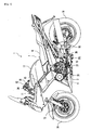
- Fig. 1 is a left side view of the motorcycle 1 according to Embodiment 1.
- front, back, left and right directions mean view directions of a crew member seating in a seat 16 described later.
- the motorcycle 1 is provided with a vehicle body 7, a front wheel 14 provided on the front side of the vehicle body 7 and a rear wheel 19 provided on the rear side of the vehicle body 7.
- the vehicle body 7 is provided with a vehicle body frame 10.
- the vehicle body frame 10 has a head pipe 11.
- a handle (handlebar) 12 is attached to the upper end part of the head pipe 11.
- the front wheel 14 is rotatably attached to the lower end of the head pipe 11 via a front fork 13.
- a power unit 3 is suspended on the vehicle body frame 10.
- a vehicle body cover 15 is attached to the vehicle body frame 10. At least a part of upper part of the vehicle body frame 10 is covered with the vehicle body cover 15.
- the seat 16 is arranged on the rear side of almost the center part of the vehicle body 7 in the front and back directions.
- a fuel tank 17 is arranged on the front side of the seat 16.
- a rear arm 18 is swingably supported by the rear half part of the vehicle body frame 10.
- the rear wheel 19 is rotatably attached to the rear end part of the rear arm 18.
- the rear wheel 19 is connected to an engine (drive source) 4 (see Fig. 3 ) to be described later via a power transmission mechanism. Thereby, the power of the engine 4 is transmitted to the rear wheel 19 to rotate the rear wheel 19.
- the motorcycle 1 is provided with a rotation suppression mechanism 50 (see Fig. 4 ) for suppressing the rotation of the rear wheel 19 at least when the engine 4 to be described later is stopped.
- the detail constitution of the rotation suppression mechanism 50 will be described later.
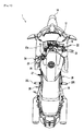
- an accelerator grip 21 is provided on the right side of the handle 12.
- a front brake lever 22 operated when braking the front wheel 14 is provided on the front side of accelerator grip 21 and on the right side of the handle 12.
- a left side grip 29 is provided on the left side of the handle 12.
- a clutch lever 24 operated in connecting and disconnecting a centrifugal clutch 2 (see Fig. 3 ) as described later is provided on the front side of the left side grip 29 and on the left side of the handle 12.
- the centrifugal clutch 2 is configured to connect the engine 4 to the rear wheel 19, when the engine 4 reaches a certain rotational speed.
- Footrests 20L and 20R are provided at a central part in the longitudinal direction of both the right and left sides of the vehicle body 7.
- a rear brake pedal 26 operated when braking the rear wheel 19 is provided slightly forward of the footrest 20R of the right side and on the right side of the vehicle body 7.
- a shift pedal 27 operated when changing the transmission gear ratio of the transmission 5 to be described later is provided slightly forward of the left side footrest 20L and on the left side of the vehicle body 7.
- a side stand 28 extending rearward is provided below the shift pedal 27 and the footrest 20L and on the left side of the vehicle body 7.
- the side stand 28 may be directly or indirectly attached to the vehicle body 7.
- the side stand 28 may be attached to, for example, the vehicle body frame 10, and may be attached to the power unit 3.
- the power unit 3 is provided with the engine 4, a transmission 5 and a clutch 2.
- the kind of the engine is not particularly limited. In this embodiment, an example in which the engine 4 is a water cooled four cycle parallel four-cylinder engine will be described.
- the engine 4 is arranged so that a cylinder shaft which is not shown slightly upwardly extends toward the forward part of the vehicle body.
- the engine 4 is provided with a crankcase 31 shown in Fig. 1 and a crankshaft 32.
- the crankshaft 32 is stored in the crankcase 31.
- the crankshaft 32 is arranged so as to extend in the vehicle width direction.
- crankshaft 32 is connected to the transmission 5 via the clutch 2.
- the transmission 5 is provided with a main shaft 33, a drive shaft 23 and a gear selection mechanism 36.
- the main shaft 33 is connected to the crankshaft 32 via the clutch 2.
- the main shaft 33 and the drive shaft 23 are respectively arranged substantially in parallel with the crankshaft 32.
- a multistage transmission gear 34 is attached to the main shaft 33.
- a plurality of transmission gears 35 corresponding to the multistage transmission gear 34 are attached to the drive shaft 23. Only the selected pair of gears of the plurality of transmission gears 34 and the plurality of transmission gears 35 are meshed with each other.
- At least one of the transmission gear 34 other than the selected transmission gear 34 of the plurality of transmission gears 34 and the transmission gear 35 other than the selected transmission gear 35 of the plurality of transmission gears 35 can be rotated with respect to the main shaft 33 or the drive shaft 23. That is, at least one of the transmission gear 34 which is not selected and the transmission gear 35 which is not selected idles with respect to the main shaft 33 or the drive shaft 23. That is, the rotation transmission between the main shaft 33 and the drive shaft 23 is carried out via only the selected transmission gear 34 and selected transmission gear 35 which are meshed with each other.
- the selection of the transmission gears 34 and 35 is carried out by the gear selection mechanism 36. Specifically, the selection of the transmission gears 34 and 35 is carried out by a shift cam 37 of the gear selection mechanism 36.
- a plurality of cam grooves 37a are formed in the outer circumferential surface of the shift cam 37.
- Each of shift forks 38 is attached to each of the cam grooves 37a.
- Each of the shift forks 38 is engaged with the prescribed transmission gears 34 and 35 of the main shaft 33 and drive shaft 23.
- each of the plurality of shift forks 38 is guided by each of the cam grooves 37a to be moved in the axial direction of the main shaft 33. Thereby, the gears meshed with each other of the transmission gears 34 and 35 are selected.
- the pair of prescribed transmission gears 34 and 35 are fixed to the main shaft 33 and the drive shaft 23, and the engine 4 is driven in a state where the clutch 2 is connected. Thereby, the power of the engine 4 is rotatably transmitted to the main shaft 33 via the clutch 2.
- the rotation transmission is carried out at a prescribed transmission gear ratio between the main shaft 33 and the drive shaft 23 via the pair of prescribed transmission gears 34 and 35, and the drive shaft 23 is rotatably driven.
- the rotation transmission is carried out by a transmission mechanism (not shown) such as a chain for connecting the drive shaft 23 to the rear wheel 19 to rotate the rear wheel 19.
- the power transmission mechanism which connects the engine 4 to the rear wheel 19, is constituted by the clutch 2, the transmission 5 and the transmission mechanism (not shown) such as the chain.
- the clutch 2 is constituted by a wet multiple disk type friction clutch.
- the clutch 2 is constituted by a centrifugal clutch eliminating the operation of the clutch lever 24 in the start or stop.
- the clutch 2 can be connected and disconnected by a rider's operation.
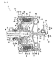
- the constitution of the clutch 2 will be described in detail with reference to Figs. 3 , 4 and 5 .
- the clutch 2 is provided with the clutch housing 46.
- the main shaft 33 is made to penetrate through the clutch housing 46.
- the clutch housing 46 has a housing body 46c.
- the housing body 46c which has one end closed by a bottom part 46a, is formed into a cylindrical shape.
- An insertion hole 46b into which the main shaft 33 is inserted is formed in the bottom part 46a.
- a plurality of pairs of arms 46d are provided on the housing body 46c. Each of the arms 46d is formed so as to project toward the inside of the diameter direction from the inner circumferential surface of the housing body 46c. Each of the arms 46d extends toward the outside of the vehicle width direction from the bottom part 46a.
- the scissors gear 45 is attached to the clutch housing 46.
- the scissors gear 45 is provided with two gears 45a and 45b, a spring 49 and two plates 51 and 52.
- the gears 45a and 45b are located between these two plates 51 and 52.
- the plates 51 and 52 are fixed to each other by a fixing means such as rivets and screws or the like with respect to the axial direction of the main shaft 33.
- the gears 45a and 45b are fixed to each other substantially with respect to the axial direction of the main shaft 33.
- the gears 45a and 45b can be mutually rotated with respect to the rotation direction.
- the teeth number of the gear 45a is equal to that of the gear 45b.
- the gears 45a and 45b are arranged so that the teeth of the gears 45a, 46b are alternately located with respect to the circumferential direction.
- the spring 49 is provided between the gears 45a and 45b. Therefore, squeeze torque is applied to the gears 45a and 45b by the spring 49. Thereby, the variable torque of the engine 4 is absorbed.
- the gear 45a of the scissors gear 45 is meshed with a gear 32a of the crankshaft 32 (see Fig. 3 ).
- the gear 45a of the scissors gear 45 is non-relative-rotatably fixed to a bottom part 46a of the clutch housing 46.
- the gear 45a of the scissors gear 45 and the clutch housing 46 are integrally rotated with the rotation of the crankshaft 32.
- a needle bearing 53 and a spacer 54 non-rotatably fixed to the main shaft 33 are arranged between the scissors gear 45 and the main shaft 33.
- the scissors gear 45 can be rotated with respect to the main shaft 33 by this needle bearing 53. That is, the rotation of the scissors gear 45 is not directly transmitted to the main shaft 33.
- the clutch boss 48 is non-rotatably fixed to the main shaft 33 by a nut 67. That is, the clutch boss 48 is rotated with the main shaft 33.
- a thrust bearing 63 is arranged between the clutch boss 48 and the scissors gear 45. Thereby, the scissors gear 45, the needle bearing 53, and the spacer 54 are regulated by the thrust bearing 63 so that they do not come close to the clutch boss 48 within a prescribed distance. The movement thereof to the side of the clutch boss 48 is regulated with respect to the axial direction of the main shaft 33.
- a plurality of friction plates (second plates) 64 are arranged inside the clutch housing 46.
- Each of the friction plates 64 is fixed to the clutch housing 46 with respect to the rotation direction of the main shaft 33. Thereby, the plurality of friction plates 64 are rotated with the clutch housing 46.
- Each of the friction plates 64 can be displaced with respect to the axial direction of the main shaft 33. Thereby, the distance between the mutually adjacent friction plates 64 is variable.
- the plurality of friction plates 64 are arranged in the axial direction of the main shaft 33.
- Clutch plates (first plates) 65 are respectively arranged between the mutually adjacent friction plates 64.
- the clutch plate 65 faces the adjacent friction plate 64.
- Each of the clutch plates 65 is fixed to clutch boss 48 with respect to the rotation direction of the main shaft 33. Thereby, the plurality of clutch plates 65 are rotated with the clutch boss 48.
- Each of the clutch plates 65 can be displaced with respect to the axial direction of the main shaft 33. Thereby, the distance between the mutually adjacent clutch plates 65 is variable.
- the plate group 66 is constituted by the plurality of friction plates 64 and the plurality of clutch plates 65.
- the pressure plate 77 is arranged outside the vehicle width direction of the main shaft 33.
- the pressure plate 77 is provided with a body part 77a and a pressing part 77b.
- the body part 77a is formed into an approximately disk-shape, and the outer side end part in the diameter direction of the body part 77a is engaged with a plurality of arms 46d. Thereby, the body part 77a cannot be rotated with respect to the clutch housing 46, and is rotated with the clutch housing 46.
- a plurality of offsprings 79 are provided between the outer side end part in the diameter direction of the body part 77a and the clutch housing 46.
- the plurality of offsprings 79 are arranged at equal spacings along the circumferential direction of the clutch housing 46.
- the body part 77a is biased toward the outside of the vehicle width direction by the offsprings 79. That is, the pressure plate 77 is biased in a direction of being separated from the plate group 66 by the offspring 79.
- the pressing part 77b formed of a ring-shaped flat body is attached to the outer circumferential part of the body part 77a of the side of the plate group 66.
- the pressing part 77b is arranged so as to face the plate group 66.
- a pressure receiving part 77c projecting toward the outside of the vehicle width direction is formed in the central part of the opposite surface to the plate group 66 of the body part 77a.
- the pressure receiving part 77c is pressed by a tip part 59a of a rack 59 of a pressing mechanism 55 to be described later.
- Two annular projections extending in the circumferential direction so as to project in the axial direction of the main shaft 33 and a plurality of projections extending in the diameter direction of the body part 77a so as to project in the axial direction of the main shaft 33 are formed in the outer circumferential part of the opposite surface to the plate group 66 of the body part 77a.
- a plurality of spaces 82 are formed by the two annular projections extending in the circumferential direction and the plurality of projections extending in the diameter direction.
- a plurality of cam surfaces 81 are formed in the outer surface in the vehicle width direction of the body part 77a forming the plurality of spaces 82.
- the plurality of cam surfaces 81 are radially arranged around the axial center of the main shaft 33.
- Each of the cam surfaces 81 is formed so as to extend toward the outside of the vehicle width direction as it goes to the outside of the diameter direction.
- a roller retainer 78 is arranged outside the pressure plate 77 in the vehicle width direction.
- the roller retainer 78 is formed into a ring-belt shape viewed from the axial direction of the main shaft 33.
- the roller retainer 78 faces a surface having the cam surface 81 of the pressure plate 77. Thereby, a space 82 being narrower toward the outside of the diameter direction of the main shaft 33 is formed by each of the cam surfaces 81 and the roller retainer 78.
- roller retainer 78 An outer side end part in the diameter direction of the roller retainer 78 is engaged with the plurality of arms 46d as well as the pressure plate 77. Thereby, the roller retainer 78 cannot be rotated with respect to the clutch housing 46. In other words, the roller retainer 78 is rotated with the clutch housing 46. On the other hand, with respect to the axial direction of the main shaft 33, the roller retainer 78 can be displaced with respect to the clutch housing 46.
- the roller retainer 78 is biased to the inside of the vehicle width direction by a disc spring 83 as an biasing member. In other words, the roller retainer 78 is biased to the side of the plate group 66 by the disc spring 83.
- a plurality of roller weights (centrifugal weights) 41 are arranged in the plurality of spaces 82.
- the roller weight 41 is revolved with the rotation of the clutch housing 46.
- the centrifugal force generated in being revolved is more than the prescribed value, the pressure plate 77 is pressed to the side of the plate group 66.
- the rotating speed of the clutch housing 46 rotated with the crankshaft 32 and the scissors gear 45 is relatively low.
- the centrifugal force which acts on the roller weight 41 is relatively small. Therefore, the roller weight 41 is located relatively inside. Therefore, the pressure plate 77 is located on the relatively right side by the biasing force of the offspring 79.
- the distance between the pressing part 77b of the pressure plate 77 and the bottom part 46a of the clutch housing 46 is relatively wide, and the plate group 66 is in a non-pressed contact condition. Therefore, the rotation of the clutch housing 46 is not transmitted to the clutch boss 48.
- the rotating speed of the crankshaft 32 is relatively enhanced, the rotating speed of the clutch housing 46 also becomes relatively higher at the same time. Therefore, the centrifugal force which acts on the roller weight 41 is enlarged as the rotating speed of the clutch housing 46 is enhanced.
- the roller weight 41 is moved to the outside. Therefore, the pressure plate 77 is pressed to the left side by the roller weight 41.
- the component force (the component force in the axial direction of the main shaft 33) of the centrifugal force which acts on the pressure plate 77 becomes larger than the biasing force of the offspring 79, the pressure plate 77 is moved to the side of the plate group 66.
- the plate group 66 is pressed and contacted, and the clutch 2 becomes in a connected state.
- the roller weight 41 presses the roller retainer 78 to the outside of the vehicle width direction. Therefore, the disc spring 83 is transformed.
- the roller retainer 78 and the roller weight 41 are biased to the side of the plate group 66 by the restoring force of the disc spring 83.
- the centrifugal clutch 2 is provided in the power transmission mechanism. Therefore, since the clutch 2 is automatically connected and disconnected according to the rotating speed of the engine 4 in the start or stop, the operation of the clutch lever 24 is eliminated. Therefore, in the motorcycle 1, an operation burden for the rider in the start or stop can be reduced.
- a clutch release mechanism 86 as a press contact release mechanism is provided in the clutch 2 of this embodiment.
- the clutch release mechanism 86 forcibly releases the pressed contact condition of the plate group 66 using a force applied by the rider of the motorcycle 1.
- the clutch release mechanism 86 enables the disengagement of the clutch 2 due to the manual operation of the rider of the motorcycle 1.
- This embodiment describes an example in which the rider of the motorcycle 1 operates the clutch lever 24 (see Fig. 2 ), thereby applying the force applied to the clutch lever 24 to the clutch release mechanism 86 to forcibly release the pressed contact condition of the plate group 66.
- the rider of the motorcycle 1 may operate the clutch lever 24 (see Fig. 2 ), thereby operating a driving mechanism such as an oil pump separately provided to apply the force generated by the oil pump to the clutch release mechanism 86 and to forcibly release the pressed contact condition of the plate group 66.
- the clutch release mechanism 86 is provided with a pushrod 43 shown in Figs. 3 and 4 , and a pushrod driving mechanism 87 shown in Figs. 3 and 5 .
- the pushrod 43 is arranged in a through-hole 33a formed in the main shaft 33.
- the through-hole 33a also serves as an oil supply hole for supplying oil to each of sliding parts or the like of the clutch 2. Specifically, oil is supplied to each of the sliding parts of the clutch 2 via a gap 89 between the inner wall of the through-hole 33a and the pushrod 43.
- the pushrod 43 is provided with a short pushrod 43a and a long pushrod 43b.
- the short pushrod 43a is arranged on the relatively outside in the vehicle width direction.
- the right side end of the short pushrod 43a faces a receiving part 77d formed in the central part of the body part of the pressure plate 77.
- An O ring 88 is attached to almost the center part of the short pushrod 43a with respect to the axial direction. This prevents the oil supplied via the gap 89 from reaching the right side in the vehicle width direction of the O ring 88.
- the short pushrod 43a is rotated with the main shaft 33 by providing the O ring 88.
- the long pushrod 43b is not rotated with the main shaft 33.
- the short pushrod 43a is relatively rotated with respect to the long pushrod 43b.
- the end surface of the short pushrod 43a of the side of the long pushrod 43b is formed into a curved surface projecting toward the side of the long pushrod 43b.
- Fig. 5 is a sectional view representing the pushrod driving mechanism 87.
- a part below the axial center of the main shaft 33 of Fig. 5 represents a state where the clutch release mechanism 86 is not driven.
- the part below the axial center of the main shaft 33 of Fig. 5 represents a state where the pushrod 43 is located on the relatively left side and the pressure plate 77 is not displaced on the right side by the pushrod 43.
- FIG. 5 represents a state where the clutch release mechanism 86 is driven.
- the part above the axial center of the main shaft 33 of Fig. 5 represents a state where the pushrod 43 is located on the relatively right side and the pressure plate 77 is displaced on the right side by the pushrod 43.
- the pushrod driving mechanism 87 is provided with a cylinder 90 and a piston 91.
- the piston 91 can be slidably moved in the axial direction of the main shaft 33 with respect to the cylinder 90.
- the piston 91 is attached to the long pushrod 43b. Thereby, the piston 91 is slid and moved, and the long pushrod 43b is also moved in the axial direction of the main shaft 33.
- an actuation chamber 92 is defined and formed.
- the actuation chamber 92 is filled with oil.
- the rider of the motorcycle 1 operates the clutch lever 24 to increase the internal pressure in the actuation chamber 92 (see Fig. 2 ).
- the piston 91 and the long pushrod 43b are displaced to the right side.
- the pressure plate 77 shown in Fig. 4 is pressed to the right side, and displaced to the right side.
- the pressing part 77b of the pressure plate 77 is separated from the plate group 66 to release the pressed contact condition of the plate group 66.
- a compression coil spring 93 is arranged between the piston 91 and the crankcase 31.
- the piston 91 is biased to the left side by the compression coil spring 93. That is, the pushrod 43 is displaced to the left side, and is biased in a connected direction of the clutch 2. Thereby, when the operation of the clutch lever 24 (see Fig. 2 ) is released by the rider of the motorcycle 1, the pushrod 43 is certainly moved to left side.
- the rotation suppression mechanism 50 suppresses the rotation of the rear wheel 19 (see Fig. 1 ) at least when the engine 4 is stopped, respectively when the motorcycle is parked by its rider.
- the interlocking mechanism 60 connects the side stand 28 to the rotation suppression mechanism 50, brings the rotation suppression mechanism 50 into an operative condition when the side stand 28 is stood, and brings the rotation suppression mechanism 50 into an inoperative condition when the side stand 28 is stored.
- the rotation suppression mechanism 50 is provided with the pressing mechanism 55 for pressing the clutch 2 in a connected direction of the clutch 2.
- the pressing mechanism 55 is provided with the rack 59 for pressing the pressure receiving part 77c of the pressure plate 77 toward the inside of the vehicle width direction and a pinion gear 58 for pressing and pulling the rack 59 on the vehicle width direction.
- the interlocking mechanism 60 is provided with a wire 56 and a lever 57.
- hydraulic means may be possible.
- the side stand 28 is provided with a supporting body 28a and a ground contact part 28b provided on one end of the supporting body 28a.
- a foot bar 28c is provided in an intermediate part of the supporting body 28a.
- One end of the wire 56 of the interlocking mechanism 60 is pin-connected to the other end 28d of the supporting body 28a.
- the side stand 28 is swingably attached to the vehicle body frame 10 or the power unit 3 or the like by a pin 28e.
- one end 57a of the lever 57 is pin-connected to the other end of the wire 56.
- the pinion gear 58 of the rotation suppression mechanism 50 is fixed to the other end of the lever 57.
- the pinion gear 58 is rotated with the swing of the lever 57.
- the teeth are formed in each of the pinion gear 58 and the rack 59.
- the pinion gear 58 and the rack 59 are arranged so that the mutual teeth are meshed with one another.
- the pinion gear 58 and the rack 59 are arranged so that the rack 59 is located relatively outside in the vehicle width direction in a state of Fig. 4 where one end 57a of the lever 57 is located on a relatively front side (upper side in Fig.
- the constitution of the motorcycle 1 is described above. Next, the interlocking operation of the side stand 28, the rotation suppression mechanism 50 and the clutch 2 when the side stand 28 is stood so that the motorcycle is prevented from being turned over in parking will be described. Before the side stand 28 is stood, the engine 4 is stopped, and the prescribed transmission gears 34 and 35 are meshed with each other to be a prescribed transmission gear ratio condition such as first speed stage.
- the tip part 59a (inner end part in the vehicle width direction) of the rack 59 is separated without being in contact with the pressure receiving part 77c of the pressure plate 77. Thereby, any force is not biased to the pressure plate 77 from the pressing mechanism 55.
- the tip part 59a (inner end part in the vehicle width direction) of the rack 59 will be in contact with the pressure receiving part 77c of the pressure plate 77 with time.
- the pressure plate 77 is pressed to the inner direction of the vehicle width direction by the rack 59.
- the force from the rack 59 which acts on the pressure plate 77 is larger than the biasing force of the offspring 79, the pressure plate 77 is moved to the side of the plate group 66. Thereby, the plate group 66 is pressed and contacted, and the clutch 2 is brought into a connected state.
- the rotation suppression mechanism 50 presses the clutch 2 to a connected direction of the centrifugal clutch 2, and forcibly brings the clutch 2 into a connected state.
- the rear wheel 19 When the clutch 2 is brought into a connected state, the rear wheel 19 is connected to the crankshaft 32 via the power transmission mechanism constituted by a transmission mechanism (not shown), the transmission 5 and the clutch 2. Thereby, the rear wheel 19 is difficult to be rotated.
- the prescribed transmission gears 34 and 35 are meshed to bring the motorcycle 1 into the prescribed transmission gear ratio condition such as first speed stage, and the side stand 28 is then stood to bring the clutch 2 into a connected state, and thereby the gear-in of the transmission can be carried out. More specifically, the gear-in can be carried out during the operation in which the side stand 28 is stood. In other words, the gear-in can be carried out until the operation in which the side stand 28 is stood is completed in the motorcycle 1, and the rotation of the rear wheel 19 can be suppressed.
- the centrifugal clutch 2 is provided in the power transmission mechanism. Therefore, the motorcycle 1 eliminates the operation of the clutch lever 24 in the start or stop. Thereby, the operation burden for the rider can be reduced.
- the motorcycle 1 is provided with the rotation suppression mechanism 50. Therefore, when the engine 4 is stopped and the side stand 28 is stood (more particularly, until the operation in which the side stand 28 is stood is completed), the rotation of the rear wheel 19 is suppressed by the rotation suppression mechanism 50. Therefore, the motorcycle 1 can stand the side stand 28 in a state where the longitudinal movement of the vehicle body 7 is suppressed. Thereby, the convenience in parking can be enhanced. Therefore, the motorcycle can reduce the operation burden for the rider, and enhance the convenience in parking.
- the rotation suppression mechanism 50 has the pressing mechanism 55 for pressing the clutch 2 in a connected direction of the centrifugal clutch 2.
- the pressing mechanism 55 of the rotation suppression mechanism 50 brings the rotation suppression mechanism 50 into an operative condition when the side stand 28 is stood to suppress the rotation of the rear wheel 19, and brings the rotation suppression mechanism 50 into an inoperative condition when the side stand 28 is stored to release the rotation suppression state of the rear wheel 19.
- the motorcycle 1, which has a simple constitution can realize the rotation suppression mechanism 50 for suppressing the rotation of the rear wheel 19 at least when the engine 4 is stopped.
- the rotation suppression mechanism 50 is provided with the pressing mechanism 55 for pressing the clutch 2 to the connected direction of the clutch 2.
- the motorcycle 1 according to Embodiment 2 is provided with the rotation suppression mechanism 50 having a rear wheel brake 93 for braking the rear wheel 19 in place of the pressing mechanism 55 of Embodiment 1.
- the motorcycle 1 according to Embodiment 2 is provided with a switching lever 94 for switching between the operative condition and inoperative condition of the rear wheel brake 93, and a pipe (hydraulic pipe) 95 for connecting the rear wheel brake 93 to the switching lever 94. Since the other constitution is almost the same as that of Embodiment 1, the description of the other constitution is omitted. Hereinafter, only the different constitution from Embodiment 1 will be described in detail.
- Embodiment 2 adopts a disk brake driven by working fluid as the rear wheel brake 93.
- the rear wheel brake 93 is provided with a disc rotor 96 attached to the end surface of a hub 19a of the rear wheel 19 by a plurality of bolts, and a caliper 97.
- the caliper 97 has a brake pad (not shown) for holding the disc rotor 96.
- the rear brake pedal 26 is also connected to the rear wheel brake 93 via a pipe 98, and the rear wheel brake 93 can be operated by the rear brake pedal 26.
- the motorcycle 1 is provided with a master cylinder (not shown) which follows the operation of the switching lever 94.
- One end of the pipe 95 is connected to the master cylinder.
- the caliper 97 includes a caliper cylinder (not shown) and a brake pad (not shown).
- the other end of the pipe 95 is connected to the caliper cylinder.
- a piston in the caliper cylinder is moved to a held direction of the disc rotor 96 by the brake pad when the working fluid is supplied via the pipe 95 from the master cylinder.
- the disc rotor 96 is held by the brake pad, the rotation of the rear wheel 19 is suppressed to brake the rear wheel 19.
- the switching lever 94 is arranged on the left side of the center of the left and right directions in the handle 12. As shown in Figs. 10(a) and 10(b) , the switching lever 94 is constituted so that the rotation of the switching lever can switch between the operative condition and inoperative condition of the rear wheel brake 93 of the rotation suppression mechanism 50. Furthermore, the switching lever 94 is arranged so that at least a part of the switching lever 94 is located on the left side of a right end 24a of the clutch lever 24 in at least one condition of the operative condition and inoperative condition of the rear wheel brake 93 of the rotation suppression mechanism 50.
- the switching lever 94 is arranged so that when the rear wheel brake 93 constituting the rotation suppression mechanism 50 is in an inoperative condition, the switching lever 94 is located on the right side of a right end 29a of the left side grip 29 provided on the left side of the handle 12 (see Fig. 10(a) ), and when the rear wheel brake 93 is in an operative condition, at least a part thereof is located on the left side of the right end 29a of the left side grip 29 (see Fig. 10(b) ).
- the motorcycle 1 is further provided with a handle lock mechanism 12a.
- the motorcycle 1 can lock the handle 12 in a state where the handle 12 is rotated leftward.
- the switching lever 94 is formed so that the rotation trajectory of the switching lever 94 interferes with the vehicle body 7 in a state where the handle 12 is locked. Thereby, the switching lever 94 can be locked so that the switching lever 94 is not rotated by locking the handle 12.
- the rotation suppression mechanism 50 has the rear wheel brake 93 for braking the rear wheel 19. Therefore, when the engine 4 is stopped and the side stand 28 is stood, the rear wheel brake 93 of the rotation suppression mechanism 50 can be brought into an operative condition to suppress the rotation of the rear wheel 19. Thereby, the motorcycle 1 can also stand the side stand 28 in parking in a state where the longitudinal movement of the vehicle body 7 is suppressed. Therefore, the motorcycle 1 according to Embodiment 2 can enhance the convenience in parking.
- the centrifugal clutch 2 is provided in the power transmission mechanism of the motorcycle 1 according to Embodiment 2. Therefore, the operation of the clutch lever 24 is eliminated in the start or stop. Thereby, the operation burden for the rider can be reduced. Therefore, the motorcycle 1 according to Embodiment 2 can also reduce the operation burden for the rider and enhance the convenience in parking.
- the motorcycle 1 is provided with the switching lever 94 for switching between the operative condition and inoperative condition of the rear wheel brake 93 of the rotation suppression mechanism 50.
- the switching lever 94 is arranged on the left side of the center of the left and right directions in the handle 12, and is arranged on the opposite side of the accelerator grip 21 in the left and right directions. Thereby, the switching lever 94 can be used for hill start or the like.
- the motorcycle 1 when the motorcycle 1 is stopped at hill or the like, not the left leg operating the shift pedal 27 but the right leg is often attached to the ground.
- the rear brake pedal 26 cannot be operated, and so-called hill start for carrying out the release operation of the rear wheel brake 93 cannot be carried out while the accelerator operation is carried out.
- the switching lever 94 is provided in this motorcycle 1. Therefore, even in a state where the right leg is attached to the ground in such a case, the release operation of the rear wheel brake 93 can be carried out by the left hand while the accelerator operation is carried out by the right hand. Therefore, the motorcycle 1 can carry out the hill start using the switching lever 94, and enhance the convenience of the travel.
- the switching lever 94 is arranged so that at least a part of the switching lever 94 is located on the left side of a right end 24a of the clutch lever 24 in at least one condition of the operative condition and inoperative condition of the rear wheel brake 93 of the rotation suppression mechanism 50.
- the switching lever 94 is arranged within a range where the switching lever 94 is operated by the rider's left hand.
- the switching lever 94 is arranged within a range where the switching lever 94 can be operated by the thumb of the left hand of the rider. Therefore, the motorcycle 1 can easily operate the switching lever 94. Therefore, the switching lever 94 can be also operated in place of the rear brake pedal 26 during movement. Thereby, the motorcycle 1 can enhance the convenience in parking and during movement.
- the switching lever 94 is arranged so that when the rear wheel brake 93 constituting the rotation suppression mechanism 50 is in an inoperative condition, the switching lever 94 is located on the right side of the right end 29a of the left side grip 29 provided on the left side of the handle 12, and when the rear wheel brake 93 is in an operative condition, at least a part thereof is located on the left side of the right end 29a of the left side grip 29. Therefore, when the rear wheel brake 93 is in an operative condition, the switching lever 94 hinders the rider from grasping the left side grip 29. Therefore, the motorcycle 1 can prevent the rider from riding with the rear wheel brake 93 in an operative condition by forgetting the switch of the switching lever 94.
- the motorcycle 1 is further provided with the handle lock mechanism 12a for locking the handle 12 in a state where the handle 12 is rotated leftward.
- the switching lever 94 of the motorcycle 1 is formed so that the rotation trajectory of the switching lever 94 interferes with the vehicle body 7. Thereby, the switching lever 94 can be locked by locking the handle 12 so that the switching lever 94 is not rotated. Therefore, the motorcycle 1 can prevent the switching lever 94 from being slily switched when the handle is locked to release the rear wheel brake 93.
- the preferred aspect examples are described using the vehicle provided with the engine 4 as the example.
- the vehicle may not be provided with the engine.
- the vehicle may be provided with any drive source.
- the vehicle may be provided with an electric motor or the like as a drive source.
- the above embodiment describes the example using the water cooled four cycle parallel four-cylinder engine 4.
- the kind of the engine is not particularly limited.
- any drive force transmission mechanism which transmits the power from the drive shaft 23 to the rear wheel 19 may be used.
- the drive force transmission mechanism may be, for example, a chain, a drive shaft and a belt or the like.
- the rider of the motorcycle 1 operates the clutch lever 24, and thereby the driving mechanism such as the oil pump may be operated.
- the power generated by the oil pump may be applied to the clutch release mechanism 86 to forcibly release the pressed contact condition of the plate group 66.
- gear-in means that the prescribed transmission gears 34 and 35 are meshed with each other in a non-neutral condition to bring the transmission 5 into a prescribed transmission gear ratio condition such as first speed stage to connect the clutch 2.
- the present teaching is useful for the motorcycle.
- a motorcycle comprising: a vehicle body; a rear wheel provided on a rear side of the vehicle body; a drive source; a power transmission mechanism for connecting the drive source to the rear wheel; a centrifugal clutch arranged in the power transmission mechanism; a transmission having a plurality of gears and arranged in the power transmission mechanism; a handle provided in the vehicle body; an accelerator grip provided on a right side of the handle; a clutch lever provided on a left side of the handle and operated when the centrifugal clutch is connected and disconnected; a shift pedal provided on a left side of the vehicle body and operated when a transmission gear ratio of the transmission is changed; a rear brake pedal provided on a right side of the vehicle body and operated when the rear wheel is braked; a side stand provided in the vehicle body; and a rotation suppression mechanism for suppressing the rotation of the rear wheel at least when the drive source is stopped.
- the rotation suppression mechanism has a pressing mechanism for pressing the centrifugal clutch in a connected direction of the centrifugal clutch.
- the centrifugal clutch comprises a clutch boss having a first plate, a clutch housing having a second plate facing an axial direction of the clutch boss with respect to the first plate, a pressure plate moved in the axial direction of the clutch boss to bring the first plate into contact with the second plate, a spring biasing the pressure plate in a direction in which the first plate is set apart from the second plate, and a centrifugal weight receiving a centrifugal force to be moved to the outside of a radial direction to move the pressure plate in a direction in which the first plate is brought into contact with the second plate, wherein the pressing mechanism has a mechanism for moving the pressure plate in the direction in which the first plate is brought into contact with the second plate.
- the rotation suppression mechanism has a rear wheel brake for braking the rear wheel.
- said motorcycle further comprises an interlocking mechanism for interlocking the side stand with the rotation suppression mechanism so that the rotation suppression mechanism is brought into an operative condition when the side stand is stood and the rotation suppression mechanism is brought into an inoperative condition when the side stand is stored.
- said motorcycle further comprises a switching lever for switching between the operative condition and inoperative condition of the rotation suppression mechanism.
- the switching lever is arranged on a left side of a center of a left and right directions of the handle.
- the switching lever is located on a left side of a right end of the clutch lever in at least one condition of the operative condition and inoperative condition of the rotation suppression mechanism.
- the switching lever is operated by a rider's left hand.
- the switching lever is operated by the thumb of the rider's left hand.
- said motorcycle further comprises a left side grip provided on a left side of the handle, wherein the switching lever is located on a right side of a right end of the left side grip in the inoperative condition of the rotation suppression mechanism, and wherein at least a part of the switching lever is located on a left side of a right end of the left side grip in the operative condition of the rotation suppression mechanism.
- the switching lever is constituted so that the rotation of the switching lever switches between the operative condition and inoperative condition of the rotation suppression mechanism; and the side stand is provided on a left side of the vehicle body, the motorcycle further comprising a handle lock mechanism for locking the handle in a state where the handle is rotated leftward to a position in which the vehicle body interferes with a rotation trajectory of the switching lever.
Landscapes
- Engineering & Computer Science (AREA)
- General Engineering & Computer Science (AREA)
- Mechanical Engineering (AREA)
- Mechanical Operated Clutches (AREA)
- One-Way And Automatic Clutches, And Combinations Of Different Clutches (AREA)
Abstract
Description
- The present invention relates to a motorcycle.
- Japanese Unexamined Patent Publication No.
07-034916 - Usually, the motorcycle is provided with a side stand. In parking, the side stand is stood so that the motorcycle is prevented from being turned over. General methods for standing the side stand include a method for stopping an engine, carrying out the gear-in of the transmission and standing the side stand. The term "gear-in" means that the transmission is not brought into a neutral condition but a prescribed transmission gear ratio condition such as first speed stage by meshing prescribed gears with one another.
- Since the rear wheel is difficult to be rotated in the method for carrying out the gear-in and standing the side stand, the side stand can be stood in a state where the longitudinal movement of the motorcycle is suppressed.
- Thus, since the motorcycle provided with the manual transmission mechanism can stand the side stand in a state where the longitudinal movement of the motorcycle is suppressed, the motorcycle has excellent convenience in parking.
- On the other hand, a motorcycle provided with a manual transmission mechanism and an added centrifugal clutch has been recently disclosed in
US Patent No. 6533056 . When the rotation speed of the engine of the motorcycle of this type is smaller than a prescribed rotation speed, the centrifugal clutch is automatically disengaged. Therefore, in the start or stop, the operation of the clutch lever or the like is eliminated. Thereby, the operation burden for the rider in the start or stop can be reduced. - However, although the motorcycle is provided with the manual transmission mechanism, the gear-in cannot be carried out in parking. Therefore, the side stand cannot be stood after the gear-in is carried out. The present invention has been accomplished in view of the problems.
- It is an objective of the present invention to reduce an operation burden for a rider of a motorcycle provided with a manual transmission mechanism and to enhance the convenience for the rider when parking said motorcycle.
- According to the present invention, said objective is solved by a motorcycle comprising: a vehicle body; a rear wheel being rotatably provided on a rear side of the vehicle body; a drive source; a power transmission mechanism including a centrifugal clutch configured to connect the drive source to the rear wheel, when the drive source reaches a certain rotational speed; and a rotation suppression mechanism configured to suppress rotation of the rear wheel at least when the drive source is stopped and the motorcycle is parked by its rider.
- In the motorcycle, the centrifugal clutch is provided in the power transmission mechanism. Therefore, in the motorcycle, the operation of the clutch lever is eliminated in the start or stop. Thereby, an operation burden for a rider can be reduced. On the other hand, the motorcycle is provided with the rotation suppression mechanism. The rotation suppression mechanism suppresses the rotation of the rear wheel in parking. Therefore, according to the motorcycle, the side stand can be stood in a state where the longitudinal movement of the vehicle body is suppressed. Thereby, the convenience in parking can be enhanced. Therefore, the motorcycle can reduce an operation burden for a rider and enhance the convenience for the rider in parking.
- Preferably, the rotation suppression mechanism has a pressing mechanism configured to press the centrifugal clutch in a connected direction of the centrifugal clutch.
- Further, preferably the vehicle body is provided with a stand, preferably a side stand, and an interlocking mechanism is configured to interlock the stand with the rotation suppression mechanism so that the rotation suppression mechanism is brought into an operative condition when the stand is folded out and the rotation suppression mechanism is brought into an inoperative condition when the stand is stored.
- Still further, preferably the pressing mechanism comprises a pinion gear and a rack meshing with said pinion gear to connect the centrifugal clutch.
- Yet further still, preferably the interlocking mechanism comprises a wire and a lever by which the stand and the rotation suppression mechanism are operatively connected.
- According to a preferred embodiment, the centrifugal clutch comprises a clutch boss having a first plate, a clutch housing having a second plate facing the first plate and a pressure plate movable in axial direction of the clutch boss to bring the first plate into contact with the second plate and, preferably, a spring biasing the pressure plate in a direction in which the first plate is set apart from the second plate, and a centrifugal weight receiving a centrifugal force to move the pressure plate in a direction in which the first plate is brought into contact with the second plate, wherein, preferably, the pressing mechanism is configured to move the pressure plate in the direction in which the first plate is brought into contact with the second plate.
- Preferably, the rotation suppression mechanism has a rear wheel brake configured to brake the rear wheel.
- According to another preferred embodiment, the motorcycle further comprises a switching lever configured to switch between an operative condition, in which the rotation of the rear wheel is suppressed, and an inoperative condition of the rotation suppression mechanism.
- Preferably, the switching lever is arranged on a left side of a handlebar of the motorcycle.
- According to a further preferred embodiment, the motorcycle further comprises a clutch lever, preferably on the left side of the handlebar, wherein at least a part of the switching lever is located on a left side of a right end of the clutch lever when the rotation suppression mechanism assumes at least one of the operative condition and the inoperative condition.
- Preferably, the switching lever can be operated by a rider's left hand.
- Further, preferably the switching lever can be operated by the thumb of the rider's left hand.
- According to another preferred embodiment, the motorcycle further comprises a left side grip provided on a left side of a handlebar of the motorcycle, wherein the switching lever is preferably located on a right side of a right end of the left side grip when the rotation suppression mechanism is in its inoperative condition, and wherein at least a part of the switching lever is preferably located on a left side of the right end of the left side grip when the rotation suppression mechanism is in its operative condition.
- Preferably, the switching lever is rotatable to switch between the operative condition and the inoperative condition of the rotation suppression mechanism, and, preferably, the motorcycle further comprises a handle lock mechanism configured to lock a handlebar of the motorcycle in a state in which the handlebar is rotated into a, preferably leftward, position in which a body of the motorcycle interferes with a rotation trajectory of the switching lever.
- Further, preferably the switching lever is operatively connected to the rear wheel brake by means of a hydraulic pipe.
- The present invention can reduce the operation burden for the rider in the motorcycle provided with the manual transmission mechanism and enhance the convenience for the rider in parking.
- In the following, the present invention is explained in greater detail by means of embodiments thereof in conjunction with the accompanying drawings, wherein:
- Fig. 1
- is a left side view of a motorcycle according to Embodiment 1;
- Fig. 2
- is a plan view of the motorcycle shown in
Fig. 1 ; - Fig. 3
- is a sectional view of a main part of a power unit;
- Fig. 4
- is a sectional view showing a clutch and a rotation suppression mechanism;
- Fig. 5
- is a sectional view showing an expanded pushrod drive mechanism of
Fig. 3 ; - Figs. 6(a) and 6(b)
- are views showing the operations of a side stand and wire;
- Fig. 7
- is a sectional view showing the clutch and the rotation suppression mechanism in the operation of the rotation suppression mechanism;
- Fig. 8
- is a view showing the rotation suppression mechanism, switching lever, rear brake pedal and rear wheel of a motorcycle according to
Embodiment 2; - Fig. 9
- is a plan view of the motorcycle according to Embodiment 2;
- Figs. 10(a) and 10(b)
- are views showing the operation of the switching lever; and
- Fig. 11
- is a plan view of the motorcycle according to Embodiment 2 in locking a handle.
- Among others, the following reference signs are used in the Figures:
- 1: motorcycle
- 2: clutch (centrifugal clutch)
- 3: power unit
- 4: engine (drive source)
- 5: transmission
- 7: vehicle body
- 12: handle (handlebar)
- 14: front wheel
- 17: fuel tank
- 19: rear wheel
- 21: accelerator grip
- 22: front brake lever
- 23: drive shaft
- 24: clutch lever
- 26: rear brake pedal
- 27: shift pedal
- 28: side stand
- 29: left side grip
- 32: crankshaft
- 33: main shaft
- 34: transmission gear
- 35: transmission gear
- 36: gear selection mechanism
- 37: shift cam
- 38: shift fork
- 41: roller weight (centrifugal weight)
- 46: clutch housing
- 48: clutch boss
- 50: rotation suppression mechanism
- 55: pressing mechanism
- 60: interlocking mechanism
- 64: friction plate (second plates)
- 65: clutch plate (first plates)
- 66: plate group
- 77: pressure plate
- 78: roller retainer
- 93: rear wheel brake
- 94: switching lever
- 95: pipe (hydraulic pipe)
- 96: disc rotor
- 97: caliper
- Hereinafter, a
motorcycle 1 provided with a manual transmission mechanism will be described in detail with reference to the drawings. However, themotorcycle 1 to be described below is a mere exemplification of the preferred embodiment to which the present teaching is applied. The present teaching is not limited to themotorcycle 1 to be described below. The motorcycle may be, for example, an off-road type motorcycle or the like. In this specification, "the motorcycle" means not only a so-called narrowly-defined motorcycle but also a broadly-defined motorcycle including an off-road vehicle or the like. -
Fig. 1 is a left side view of themotorcycle 1 according toEmbodiment 1. In the following description, front, back, left and right directions mean view directions of a crew member seating in aseat 16 described later. - As shown in
Fig. 1 , themotorcycle 1 is provided with avehicle body 7, afront wheel 14 provided on the front side of thevehicle body 7 and arear wheel 19 provided on the rear side of thevehicle body 7. - The
vehicle body 7 is provided with avehicle body frame 10. Thevehicle body frame 10 has a head pipe 11. A handle (handlebar) 12 is attached to the upper end part of the head pipe 11. On the other hand, thefront wheel 14 is rotatably attached to the lower end of the head pipe 11 via afront fork 13. - A
power unit 3 is suspended on thevehicle body frame 10. Avehicle body cover 15 is attached to thevehicle body frame 10. At least a part of upper part of thevehicle body frame 10 is covered with thevehicle body cover 15. Theseat 16 is arranged on the rear side of almost the center part of thevehicle body 7 in the front and back directions. Afuel tank 17 is arranged on the front side of theseat 16. - A
rear arm 18 is swingably supported by the rear half part of thevehicle body frame 10. Therear wheel 19 is rotatably attached to the rear end part of therear arm 18. Therear wheel 19 is connected to an engine (drive source) 4 (seeFig. 3 ) to be described later via a power transmission mechanism. Thereby, the power of the engine 4 is transmitted to therear wheel 19 to rotate therear wheel 19. - The
motorcycle 1 is provided with a rotation suppression mechanism 50 (seeFig. 4 ) for suppressing the rotation of therear wheel 19 at least when the engine 4 to be described later is stopped. The detail constitution of therotation suppression mechanism 50 will be described later. - As shown in
Fig. 2 , anaccelerator grip 21 is provided on the right side of thehandle 12. Afront brake lever 22 operated when braking thefront wheel 14 is provided on the front side ofaccelerator grip 21 and on the right side of thehandle 12. On the other hand, aleft side grip 29 is provided on the left side of thehandle 12. Aclutch lever 24 operated in connecting and disconnecting a centrifugal clutch 2 (seeFig. 3 ) as described later is provided on the front side of theleft side grip 29 and on the left side of thehandle 12. Thecentrifugal clutch 2 is configured to connect the engine 4 to therear wheel 19, when the engine 4 reaches a certain rotational speed. -
Footrests vehicle body 7. Arear brake pedal 26 operated when braking therear wheel 19 is provided slightly forward of thefootrest 20R of the right side and on the right side of thevehicle body 7. On the other hand, ashift pedal 27 operated when changing the transmission gear ratio of thetransmission 5 to be described later is provided slightly forward of theleft side footrest 20L and on the left side of thevehicle body 7. As shown inFig. 1 , aside stand 28 extending rearward is provided below theshift pedal 27 and thefootrest 20L and on the left side of thevehicle body 7. The side stand 28 may be directly or indirectly attached to thevehicle body 7. The side stand 28 may be attached to, for example, thevehicle body frame 10, and may be attached to thepower unit 3. - Next, the constitution of the
power unit 3 will be described in detail with reference toFig. 3 . As shown inFig. 3 , thepower unit 3 is provided with the engine 4, atransmission 5 and aclutch 2. The kind of the engine is not particularly limited. In this embodiment, an example in which the engine 4 is a water cooled four cycle parallel four-cylinder engine will be described. - The engine 4 is arranged so that a cylinder shaft which is not shown slightly upwardly extends toward the forward part of the vehicle body. The engine 4 is provided with a
crankcase 31 shown inFig. 1 and acrankshaft 32. Thecrankshaft 32 is stored in thecrankcase 31. Thecrankshaft 32 is arranged so as to extend in the vehicle width direction. - As shown in
Fig. 3 , thecrankshaft 32 is connected to thetransmission 5 via theclutch 2. Thetransmission 5 is provided with amain shaft 33, adrive shaft 23 and agear selection mechanism 36. Themain shaft 33 is connected to thecrankshaft 32 via theclutch 2. Themain shaft 33 and thedrive shaft 23 are respectively arranged substantially in parallel with thecrankshaft 32. - A
multistage transmission gear 34 is attached to themain shaft 33. On the other hand, a plurality of transmission gears 35 corresponding to themultistage transmission gear 34 are attached to thedrive shaft 23. Only the selected pair of gears of the plurality of transmission gears 34 and the plurality of transmission gears 35 are meshed with each other. At least one of thetransmission gear 34 other than the selectedtransmission gear 34 of the plurality of transmission gears 34 and thetransmission gear 35 other than the selectedtransmission gear 35 of the plurality of transmission gears 35 can be rotated with respect to themain shaft 33 or thedrive shaft 23. That is, at least one of thetransmission gear 34 which is not selected and thetransmission gear 35 which is not selected idles with respect to themain shaft 33 or thedrive shaft 23. That is, the rotation transmission between themain shaft 33 and thedrive shaft 23 is carried out via only the selectedtransmission gear 34 and selectedtransmission gear 35 which are meshed with each other. - The selection of the transmission gears 34 and 35 is carried out by the
gear selection mechanism 36. Specifically, the selection of the transmission gears 34 and 35 is carried out by ashift cam 37 of thegear selection mechanism 36. A plurality ofcam grooves 37a are formed in the outer circumferential surface of theshift cam 37. Each ofshift forks 38 is attached to each of thecam grooves 37a. Each of theshift forks 38 is engaged with the prescribed transmission gears 34 and 35 of themain shaft 33 and driveshaft 23. By the rotation of theshift cam 37, each of the plurality ofshift forks 38 is guided by each of thecam grooves 37a to be moved in the axial direction of themain shaft 33. Thereby, the gears meshed with each other of the transmission gears 34 and 35 are selected. Specifically, only a pair of gears at a position corresponding to the rotation angle of theshift cam 37 of the plurality of transmission gears 34 and 35 are respectively in a fixed state due to a spline with respect to themain shaft 33 and thedrive shaft 23. Thereby, the position of the transmission gear is determined, and the rotation transmission is carried out at a prescribed transmission gear ratio between themain shaft 33 and thedrive shaft 23 via the transmission gears 34 and 35. Thisgear selection mechanism 36 is operated by theshift pedal 27 shown inFig. 1 . - In this constitution, the pair of prescribed transmission gears 34 and 35 are fixed to the
main shaft 33 and thedrive shaft 23, and the engine 4 is driven in a state where theclutch 2 is connected. Thereby, the power of the engine 4 is rotatably transmitted to themain shaft 33 via theclutch 2. The rotation transmission is carried out at a prescribed transmission gear ratio between themain shaft 33 and thedrive shaft 23 via the pair of prescribed transmission gears 34 and 35, and thedrive shaft 23 is rotatably driven. When thedrive shaft 23 is rotatably driven, the rotation transmission is carried out by a transmission mechanism (not shown) such as a chain for connecting thedrive shaft 23 to therear wheel 19 to rotate therear wheel 19. In this embodiment, the power transmission mechanism, which connects the engine 4 to therear wheel 19, is constituted by theclutch 2, thetransmission 5 and the transmission mechanism (not shown) such as the chain. - In this embodiment, the
clutch 2 is constituted by a wet multiple disk type friction clutch. Theclutch 2 is constituted by a centrifugal clutch eliminating the operation of theclutch lever 24 in the start or stop. The clutch 2 can be connected and disconnected by a rider's operation. Hereinafter, the constitution of the clutch 2 will be described in detail with reference toFigs. 3 ,4 and5 . - As shown in
Fig. 4 , theclutch 2 is provided with theclutch housing 46. Themain shaft 33 is made to penetrate through theclutch housing 46. Theclutch housing 46 has ahousing body 46c. Thehousing body 46c, which has one end closed by abottom part 46a, is formed into a cylindrical shape. Aninsertion hole 46b into which themain shaft 33 is inserted is formed in thebottom part 46a. A plurality of pairs ofarms 46d are provided on thehousing body 46c. Each of thearms 46d is formed so as to project toward the inside of the diameter direction from the inner circumferential surface of thehousing body 46c. Each of thearms 46d extends toward the outside of the vehicle width direction from thebottom part 46a. - The scissors gear 45 is attached to the
clutch housing 46. The scissors gear 45 is provided with twogears spring 49 and twoplates gears plates plates main shaft 33. Thereby, thegears main shaft 33. On the other hand, thegears - The teeth number of the
gear 45a is equal to that of thegear 45b. Thegears gears spring 49 is provided between thegears gears spring 49. Thereby, the variable torque of the engine 4 is absorbed. - The
gear 45a of thescissors gear 45 is meshed with agear 32a of the crankshaft 32 (seeFig. 3 ). Thegear 45a of thescissors gear 45 is non-relative-rotatably fixed to abottom part 46a of theclutch housing 46. By the constitution, thegear 45a of thescissors gear 45 and theclutch housing 46 are integrally rotated with the rotation of thecrankshaft 32. - A
needle bearing 53 and aspacer 54 non-rotatably fixed to themain shaft 33 are arranged between thescissors gear 45 and themain shaft 33. The scissors gear 45 can be rotated with respect to themain shaft 33 by thisneedle bearing 53. That is, the rotation of thescissors gear 45 is not directly transmitted to themain shaft 33. - The
clutch boss 48 is non-rotatably fixed to themain shaft 33 by anut 67. That is, theclutch boss 48 is rotated with themain shaft 33. Athrust bearing 63 is arranged between theclutch boss 48 and thescissors gear 45. Thereby, thescissors gear 45, theneedle bearing 53, and thespacer 54 are regulated by the thrust bearing 63 so that they do not come close to theclutch boss 48 within a prescribed distance. The movement thereof to the side of theclutch boss 48 is regulated with respect to the axial direction of themain shaft 33. - A plurality of friction plates (second plates) 64 are arranged inside the
clutch housing 46. Each of thefriction plates 64 is fixed to theclutch housing 46 with respect to the rotation direction of themain shaft 33. Thereby, the plurality offriction plates 64 are rotated with theclutch housing 46. Each of thefriction plates 64 can be displaced with respect to the axial direction of themain shaft 33. Thereby, the distance between the mutuallyadjacent friction plates 64 is variable. - The plurality of
friction plates 64 are arranged in the axial direction of themain shaft 33. Clutch plates (first plates) 65 are respectively arranged between the mutuallyadjacent friction plates 64. Theclutch plate 65 faces theadjacent friction plate 64. Each of theclutch plates 65 is fixed toclutch boss 48 with respect to the rotation direction of themain shaft 33. Thereby, the plurality ofclutch plates 65 are rotated with theclutch boss 48. Each of theclutch plates 65 can be displaced with respect to the axial direction of themain shaft 33. Thereby, the distance between the mutually adjacentclutch plates 65 is variable. - In this embodiment, the
plate group 66 is constituted by the plurality offriction plates 64 and the plurality ofclutch plates 65. - The
pressure plate 77 is arranged outside the vehicle width direction of themain shaft 33. Thepressure plate 77 is provided with abody part 77a and apressing part 77b. - The
body part 77a is formed into an approximately disk-shape, and the outer side end part in the diameter direction of thebody part 77a is engaged with a plurality ofarms 46d. Thereby, thebody part 77a cannot be rotated with respect to theclutch housing 46, and is rotated with theclutch housing 46. A plurality ofoffsprings 79 are provided between the outer side end part in the diameter direction of thebody part 77a and theclutch housing 46. The plurality ofoffsprings 79 are arranged at equal spacings along the circumferential direction of theclutch housing 46. Thebody part 77a is biased toward the outside of the vehicle width direction by theoffsprings 79. That is, thepressure plate 77 is biased in a direction of being separated from theplate group 66 by theoffspring 79. - The
pressing part 77b formed of a ring-shaped flat body is attached to the outer circumferential part of thebody part 77a of the side of theplate group 66. Thepressing part 77b is arranged so as to face theplate group 66. - On the other hand, a
pressure receiving part 77c projecting toward the outside of the vehicle width direction is formed in the central part of the opposite surface to theplate group 66 of thebody part 77a. Thepressure receiving part 77c is pressed by atip part 59a of arack 59 of apressing mechanism 55 to be described later. Two annular projections extending in the circumferential direction so as to project in the axial direction of themain shaft 33 and a plurality of projections extending in the diameter direction of thebody part 77a so as to project in the axial direction of themain shaft 33 are formed in the outer circumferential part of the opposite surface to theplate group 66 of thebody part 77a. A plurality ofspaces 82 are formed by the two annular projections extending in the circumferential direction and the plurality of projections extending in the diameter direction. - A plurality of cam surfaces 81 are formed in the outer surface in the vehicle width direction of the
body part 77a forming the plurality ofspaces 82. The plurality of cam surfaces 81 are radially arranged around the axial center of themain shaft 33. Each of the cam surfaces 81 is formed so as to extend toward the outside of the vehicle width direction as it goes to the outside of the diameter direction. - A
roller retainer 78 is arranged outside thepressure plate 77 in the vehicle width direction. Theroller retainer 78 is formed into a ring-belt shape viewed from the axial direction of themain shaft 33. Theroller retainer 78 faces a surface having thecam surface 81 of thepressure plate 77. Thereby, aspace 82 being narrower toward the outside of the diameter direction of themain shaft 33 is formed by each of the cam surfaces 81 and theroller retainer 78. - An outer side end part in the diameter direction of the
roller retainer 78 is engaged with the plurality ofarms 46d as well as thepressure plate 77. Thereby, theroller retainer 78 cannot be rotated with respect to theclutch housing 46. In other words, theroller retainer 78 is rotated with theclutch housing 46. On the other hand, with respect to the axial direction of themain shaft 33, theroller retainer 78 can be displaced with respect to theclutch housing 46. - The
roller retainer 78 is biased to the inside of the vehicle width direction by adisc spring 83 as an biasing member. In other words, theroller retainer 78 is biased to the side of theplate group 66 by thedisc spring 83. - A plurality of roller weights (centrifugal weights) 41 are arranged in the plurality of
spaces 82. Theroller weight 41 is revolved with the rotation of theclutch housing 46. When the centrifugal force generated in being revolved is more than the prescribed value, thepressure plate 77 is pressed to the side of theplate group 66. - Specifically, in an idling state, the rotating speed of the
clutch housing 46 rotated with thecrankshaft 32 and thescissors gear 45 is relatively low. Thereby, the centrifugal force which acts on theroller weight 41 is relatively small. Therefore, theroller weight 41 is located relatively inside. Therefore, thepressure plate 77 is located on the relatively right side by the biasing force of theoffspring 79. As a result, the distance between thepressing part 77b of thepressure plate 77 and thebottom part 46a of theclutch housing 46 is relatively wide, and theplate group 66 is in a non-pressed contact condition. Therefore, the rotation of theclutch housing 46 is not transmitted to theclutch boss 48. - When the rotating speed of the
crankshaft 32 is relatively enhanced, the rotating speed of theclutch housing 46 also becomes relatively higher at the same time. Therefore, the centrifugal force which acts on theroller weight 41 is enlarged as the rotating speed of theclutch housing 46 is enhanced. When the centrifugal force which acts on theroller weight 41 is more than the prescribed value, theroller weight 41 is moved to the outside. Therefore, thepressure plate 77 is pressed to the left side by theroller weight 41. When the component force (the component force in the axial direction of the main shaft 33) of the centrifugal force which acts on thepressure plate 77 becomes larger than the biasing force of theoffspring 79, thepressure plate 77 is moved to the side of theplate group 66. Thereby, theplate group 66 is pressed and contacted, and theclutch 2 becomes in a connected state. When theroller weight 41 is moved to the outside, theroller weight 41 presses theroller retainer 78 to the outside of the vehicle width direction. Therefore, thedisc spring 83 is transformed. When thedisc spring 83 is transformed, theroller retainer 78 and theroller weight 41 are biased to the side of theplate group 66 by the restoring force of thedisc spring 83. - Thus, when the
plate group 66 is pressed and contacted and theclutch 2 is connected, the rotation of theclutch housing 46 is transmitted to theclutch boss 48 via theplate group 66. Thereby, theclutch boss 48 is rotated with theclutch housing 46. - On the other hand, when the rotating speed of the
crankshaft 32 becomes lower in a state where theclutch 2 is connected, the centrifugal force which acts on theroller weight 41 becomes lower. Therefore, theroller weight 41 is moved to the inside of the centrifugal direction. As a result, thepressure plate 77 is moved to the right side by the biasing force of theoffspring 79, and theclutch 2 is disengaged. - Thus, in the
motorcycle 1, thecentrifugal clutch 2 is provided in the power transmission mechanism. Therefore, since theclutch 2 is automatically connected and disconnected according to the rotating speed of the engine 4 in the start or stop, the operation of theclutch lever 24 is eliminated. Therefore, in themotorcycle 1, an operation burden for the rider in the start or stop can be reduced. - A
clutch release mechanism 86 as a press contact release mechanism is provided in theclutch 2 of this embodiment. Theclutch release mechanism 86 forcibly releases the pressed contact condition of theplate group 66 using a force applied by the rider of themotorcycle 1. Theclutch release mechanism 86 enables the disengagement of theclutch 2 due to the manual operation of the rider of themotorcycle 1. - This embodiment describes an example in which the rider of the
motorcycle 1 operates the clutch lever 24 (seeFig. 2 ), thereby applying the force applied to theclutch lever 24 to theclutch release mechanism 86 to forcibly release the pressed contact condition of theplate group 66. However, the present teaching is not limited thereto. For example, the rider of themotorcycle 1 may operate the clutch lever 24 (seeFig. 2 ), thereby operating a driving mechanism such as an oil pump separately provided to apply the force generated by the oil pump to theclutch release mechanism 86 and to forcibly release the pressed contact condition of theplate group 66. - The
clutch release mechanism 86 is provided with apushrod 43 shown inFigs. 3 and4 , and apushrod driving mechanism 87 shown inFigs. 3 and5 . As shown inFig. 4 , thepushrod 43 is arranged in a through-hole 33a formed in themain shaft 33. The through-hole 33a also serves as an oil supply hole for supplying oil to each of sliding parts or the like of theclutch 2. Specifically, oil is supplied to each of the sliding parts of theclutch 2 via agap 89 between the inner wall of the through-hole 33a and thepushrod 43. - The
pushrod 43 is provided with ashort pushrod 43a and along pushrod 43b. Theshort pushrod 43a is arranged on the relatively outside in the vehicle width direction. The right side end of theshort pushrod 43a faces a receivingpart 77d formed in the central part of the body part of thepressure plate 77. AnO ring 88 is attached to almost the center part of theshort pushrod 43a with respect to the axial direction. This prevents the oil supplied via thegap 89 from reaching the right side in the vehicle width direction of theO ring 88. And, theshort pushrod 43a is rotated with themain shaft 33 by providing theO ring 88. On the other hand, thelong pushrod 43b is not rotated with themain shaft 33. Thereby, when themain shaft 33 is rotated, theshort pushrod 43a is relatively rotated with respect to thelong pushrod 43b. In view of this constitution, the end surface of theshort pushrod 43a of the side of thelong pushrod 43b is formed into a curved surface projecting toward the side of thelong pushrod 43b. Thereby, the sliding resistance between theshort pushrod 43a and thelong pushrod 43b when theshort pushrod 43a is rotated is reduced. - As shown in
Fig. 3 , the left side end of thelong pushrod 43b is located on the left side of the left side end of themain shaft 33, and leads to thepushrod driving mechanism 87.
Fig. 5 is a sectional view representing thepushrod driving mechanism 87. A part below the axial center of themain shaft 33 ofFig. 5 represents a state where theclutch release mechanism 86 is not driven. In other words, the part below the axial center of themain shaft 33 ofFig. 5 represents a state where thepushrod 43 is located on the relatively left side and thepressure plate 77 is not displaced on the right side by thepushrod 43. On the other hand, a part above the axial center of themain shaft 33 ofFig. 5 represents a state where theclutch release mechanism 86 is driven. In other words, the part above the axial center of themain shaft 33 ofFig. 5 represents a state where thepushrod 43 is located on the relatively right side and thepressure plate 77 is displaced on the right side by thepushrod 43. - As shown in
Fig. 5 , thepushrod driving mechanism 87 is provided with acylinder 90 and apiston 91. Thepiston 91 can be slidably moved in the axial direction of themain shaft 33 with respect to thecylinder 90. Thepiston 91 is attached to thelong pushrod 43b. Thereby, thepiston 91 is slid and moved, and thelong pushrod 43b is also moved in the axial direction of themain shaft 33. - Between the
piston 91 and thecylinder 90, anactuation chamber 92 is defined and formed. Theactuation chamber 92 is filled with oil. The rider of themotorcycle 1 operates theclutch lever 24 to increase the internal pressure in the actuation chamber 92 (seeFig. 2 ). Thereby, thepiston 91 and thelong pushrod 43b are displaced to the right side. Thepressure plate 77 shown inFig. 4 is pressed to the right side, and displaced to the right side. As a result, thepressing part 77b of thepressure plate 77 is separated from theplate group 66 to release the pressed contact condition of theplate group 66. - A
compression coil spring 93 is arranged between thepiston 91 and thecrankcase 31. Thepiston 91 is biased to the left side by thecompression coil spring 93. That is, thepushrod 43 is displaced to the left side, and is biased in a connected direction of theclutch 2. Thereby, when the operation of the clutch lever 24 (seeFig. 2 ) is released by the rider of themotorcycle 1, thepushrod 43 is certainly moved to left side. - Next, the
rotation suppression mechanism 50 and the interlocking mechanism 60 for interlocking the side stand 28 with therotation suppression mechanism 50 will be described. As described above, therotation suppression mechanism 50 suppresses the rotation of the rear wheel 19 (seeFig. 1 ) at least when the engine 4 is stopped, respectively when the motorcycle is parked by its rider. On the other hand, the interlocking mechanism 60 connects the side stand 28 to therotation suppression mechanism 50, brings therotation suppression mechanism 50 into an operative condition when the side stand 28 is stood, and brings therotation suppression mechanism 50 into an inoperative condition when the side stand 28 is stored. - As shown in
Fig. 4 , in this embodiment, therotation suppression mechanism 50 is provided with thepressing mechanism 55 for pressing the clutch 2 in a connected direction of theclutch 2. In this embodiment, thepressing mechanism 55 is provided with therack 59 for pressing thepressure receiving part 77c of thepressure plate 77 toward the inside of the vehicle width direction and apinion gear 58 for pressing and pulling therack 59 on the vehicle width direction. On the other hand, the interlocking mechanism 60 is provided with awire 56 and alever 57. However, also hydraulic means may be possible. - As shown in
Fig. 6 , the side stand 28 is provided with a supportingbody 28a and aground contact part 28b provided on one end of the supportingbody 28a. Afoot bar 28c is provided in an intermediate part of the supportingbody 28a. One end of thewire 56 of the interlocking mechanism 60 is pin-connected to theother end 28d of the supportingbody 28a. The side stand 28 is swingably attached to thevehicle body frame 10 or thepower unit 3 or the like by apin 28e. - As shown in
Fig. 4 , oneend 57a of thelever 57 is pin-connected to the other end of thewire 56. Thepinion gear 58 of therotation suppression mechanism 50 is fixed to the other end of thelever 57. Thepinion gear 58 is rotated with the swing of thelever 57. The teeth are formed in each of thepinion gear 58 and therack 59. Thepinion gear 58 and therack 59 are arranged so that the mutual teeth are meshed with one another. In this embodiment, thepinion gear 58 and therack 59 are arranged so that therack 59 is located relatively outside in the vehicle width direction in a state ofFig. 4 where oneend 57a of thelever 57 is located on a relatively front side (upper side inFig. 4 ) in the front and back directions of themotorcycle 1, and are arranged so that therack 59 is located relatively inside in the vehicle width direction in a state ofFig. 7 where oneend 57a of thelever 57 is located on the relatively rear side (lower side inFig. 7 ) in the front and back directions. - The constitution of the
motorcycle 1 is described above. Next, the interlocking operation of theside stand 28, therotation suppression mechanism 50 and the clutch 2 when the side stand 28 is stood so that the motorcycle is prevented from being turned over in parking will be described. Before the side stand 28 is stood, the engine 4 is stopped, and the prescribed transmission gears 34 and 35 are meshed with each other to be a prescribed transmission gear ratio condition such as first speed stage. - As shown in
Fig. 6(a) , when the side stand 28 is flipped up, theother end 28d of the supportingbody 28a of the side stand 28 is located on a relatively front side (left side inFig. 6 (a) ) with respect to the front and back directions of themotorcycle 1. Therefore, thewire 56 having one end pin-connected to theother end 28d of the supportingbody 28a is also located on a relatively front side. Thereby, as shown inFig. 4 , oneend 57a of thelever 57 is also located on a relatively front side, and therack 59 is located relatively outside in the vehicle width direction. At this time, thetip part 59a (inner end part in the vehicle width direction) of therack 59 is separated without being in contact with thepressure receiving part 77c of thepressure plate 77. Thereby, any force is not biased to thepressure plate 77 from thepressing mechanism 55. - On the other hand, as shown in
Fig. 6(b) , when the side stand 28 is stood, the supportingbody 28a of the side stand 28 is swung around thepin 28e. Thereby, theground contact part 28b located on one end of the supportingbody 28a is forwardly and downwardly moved, and theother end 28d of the supportingbody 28a is backwardly moved. - When the
other end 28d of the supportingbody 28a is backwardly moved, thewire 56 is backwardly pulled by theother end 28d of the supportingbody 28a. When thewire 56 is backwardly pulled, as shown inFig. 7 , oneend 57a of thelever 57 is pulled to the rear side, and thelever 57 is swung. At the same time, oneend 57a of thelever 57 is moved to the rear side. Thepinion gear 58 is rotated clockwise inFig. 7 . As a result, therack 59 having teeth meshed with the teeth of thepinion gear 58 is sent out in the inner direction of the vehicle width direction by thepinion gear 58. - When the
rack 59 is sent out to the inner direction of the vehicle width direction by a prescribed length, thetip part 59a (inner end part in the vehicle width direction) of therack 59 will be in contact with thepressure receiving part 77c of thepressure plate 77 with time. When therack 59 is further sent out to the same direction, thepressure plate 77 is pressed to the inner direction of the vehicle width direction by therack 59. When the force from therack 59 which acts on thepressure plate 77 is larger than the biasing force of theoffspring 79, thepressure plate 77 is moved to the side of theplate group 66. Thereby, theplate group 66 is pressed and contacted, and theclutch 2 is brought into a connected state. Thus, when therotation suppression mechanism 50 is interlocked with the side stand 28 by the interlocking mechanism 60 and the side stand 28 is stood, therotation suppression mechanism 50 presses the clutch 2 to a connected direction of thecentrifugal clutch 2, and forcibly brings the clutch 2 into a connected state. - When the clutch 2 is brought into a connected state, the
rear wheel 19 is connected to thecrankshaft 32 via the power transmission mechanism constituted by a transmission mechanism (not shown), thetransmission 5 and theclutch 2. Thereby, therear wheel 19 is difficult to be rotated. Thus, the prescribed transmission gears 34 and 35 are meshed to bring themotorcycle 1 into the prescribed transmission gear ratio condition such as first speed stage, and the side stand 28 is then stood to bring the clutch 2 into a connected state, and thereby the gear-in of the transmission can be carried out. More specifically, the gear-in can be carried out during the operation in which the side stand 28 is stood. In other words, the gear-in can be carried out until the operation in which the side stand 28 is stood is completed in themotorcycle 1, and the rotation of therear wheel 19 can be suppressed. - As described above, in the
motorcycle 1, thecentrifugal clutch 2 is provided in the power transmission mechanism. Therefore, themotorcycle 1 eliminates the operation of theclutch lever 24 in the start or stop. Thereby, the operation burden for the rider can be reduced. On the other hand, themotorcycle 1 is provided with therotation suppression mechanism 50. Therefore, when the engine 4 is stopped and the side stand 28 is stood (more particularly, until the operation in which the side stand 28 is stood is completed), the rotation of therear wheel 19 is suppressed by therotation suppression mechanism 50. Therefore, themotorcycle 1 can stand the side stand 28 in a state where the longitudinal movement of thevehicle body 7 is suppressed. Thereby, the convenience in parking can be enhanced. Therefore, the motorcycle can reduce the operation burden for the rider, and enhance the convenience in parking. - In the
motorcycle 1, therotation suppression mechanism 50 has thepressing mechanism 55 for pressing the clutch 2 in a connected direction of thecentrifugal clutch 2. Thepressing mechanism 55 of therotation suppression mechanism 50 brings therotation suppression mechanism 50 into an operative condition when the side stand 28 is stood to suppress the rotation of therear wheel 19, and brings therotation suppression mechanism 50 into an inoperative condition when the side stand 28 is stored to release the rotation suppression state of therear wheel 19. Thus, themotorcycle 1, which has a simple constitution, can realize therotation suppression mechanism 50 for suppressing the rotation of therear wheel 19 at least when the engine 4 is stopped. - In the
motorcycle 1 according toEmbodiment 1, therotation suppression mechanism 50 is provided with thepressing mechanism 55 for pressing the clutch 2 to the connected direction of theclutch 2. As shown inFig. 8 , themotorcycle 1 according toEmbodiment 2 is provided with therotation suppression mechanism 50 having arear wheel brake 93 for braking therear wheel 19 in place of thepressing mechanism 55 ofEmbodiment 1. Themotorcycle 1 according toEmbodiment 2 is provided with a switchinglever 94 for switching between the operative condition and inoperative condition of therear wheel brake 93, and a pipe (hydraulic pipe) 95 for connecting therear wheel brake 93 to the switchinglever 94. Since the other constitution is almost the same as that ofEmbodiment 1, the description of the other constitution is omitted. Hereinafter, only the different constitution fromEmbodiment 1 will be described in detail. -
Embodiment 2 adopts a disk brake driven by working fluid as therear wheel brake 93. As shown inFig. 8 , therear wheel brake 93 is provided with adisc rotor 96 attached to the end surface of ahub 19a of therear wheel 19 by a plurality of bolts, and acaliper 97. - The
caliper 97 has a brake pad (not shown) for holding thedisc rotor 96. Therear brake pedal 26 is also connected to therear wheel brake 93 via apipe 98, and therear wheel brake 93 can be operated by therear brake pedal 26. - The
motorcycle 1 is provided with a master cylinder (not shown) which follows the operation of the switchinglever 94. One end of thepipe 95 is connected to the master cylinder. On the other hand, thecaliper 97 includes a caliper cylinder (not shown) and a brake pad (not shown). The other end of thepipe 95 is connected to the caliper cylinder. A piston in the caliper cylinder is moved to a held direction of thedisc rotor 96 by the brake pad when the working fluid is supplied via thepipe 95 from the master cylinder. When thedisc rotor 96 is held by the brake pad, the rotation of therear wheel 19 is suppressed to brake therear wheel 19. - As shown in
Fig. 9 , the switchinglever 94 is arranged on the left side of the center of the left and right directions in thehandle 12. As shown inFigs. 10(a) and 10(b) , the switchinglever 94 is constituted so that the rotation of the switching lever can switch between the operative condition and inoperative condition of therear wheel brake 93 of therotation suppression mechanism 50. Furthermore, the switchinglever 94 is arranged so that at least a part of the switchinglever 94 is located on the left side of aright end 24a of theclutch lever 24 in at least one condition of the operative condition and inoperative condition of therear wheel brake 93 of therotation suppression mechanism 50. The switchinglever 94 is arranged so that when therear wheel brake 93 constituting therotation suppression mechanism 50 is in an inoperative condition, the switchinglever 94 is located on the right side of aright end 29a of theleft side grip 29 provided on the left side of the handle 12 (seeFig. 10(a) ), and when therear wheel brake 93 is in an operative condition, at least a part thereof is located on the left side of theright end 29a of the left side grip 29 (seeFig. 10(b) ). - The
motorcycle 1 is further provided with ahandle lock mechanism 12a. Thereby, as shown inFig. 11 , themotorcycle 1 can lock thehandle 12 in a state where thehandle 12 is rotated leftward. As shown inFig. 11 , in this embodiment, the switchinglever 94 is formed so that the rotation trajectory of the switchinglever 94 interferes with thevehicle body 7 in a state where thehandle 12 is locked. Thereby, the switchinglever 94 can be locked so that the switchinglever 94 is not rotated by locking thehandle 12. - As described above, in the
motorcycle 1 according toEmbodiment 2, therotation suppression mechanism 50 has therear wheel brake 93 for braking therear wheel 19. Therefore, when the engine 4 is stopped and the side stand 28 is stood, therear wheel brake 93 of therotation suppression mechanism 50 can be brought into an operative condition to suppress the rotation of therear wheel 19. Thereby, themotorcycle 1 can also stand the side stand 28 in parking in a state where the longitudinal movement of thevehicle body 7 is suppressed. Therefore, themotorcycle 1 according toEmbodiment 2 can enhance the convenience in parking. As inEmbodiment 1, thecentrifugal clutch 2 is provided in the power transmission mechanism of themotorcycle 1 according toEmbodiment 2. Therefore, the operation of theclutch lever 24 is eliminated in the start or stop. Thereby, the operation burden for the rider can be reduced. Therefore, themotorcycle 1 according toEmbodiment 2 can also reduce the operation burden for the rider and enhance the convenience in parking. - The
motorcycle 1 is provided with the switchinglever 94 for switching between the operative condition and inoperative condition of therear wheel brake 93 of therotation suppression mechanism 50. The switchinglever 94 is arranged on the left side of the center of the left and right directions in thehandle 12, and is arranged on the opposite side of theaccelerator grip 21 in the left and right directions. Thereby, the switchinglever 94 can be used for hill start or the like. - Specifically, when the
motorcycle 1 is stopped at hill or the like, not the left leg operating theshift pedal 27 but the right leg is often attached to the ground. However, in a state where the right leg is attached to the ground, therear brake pedal 26 cannot be operated, and so-called hill start for carrying out the release operation of therear wheel brake 93 cannot be carried out while the accelerator operation is carried out. However, the switchinglever 94 is provided in thismotorcycle 1. Therefore, even in a state where the right leg is attached to the ground in such a case, the release operation of therear wheel brake 93 can be carried out by the left hand while the accelerator operation is carried out by the right hand. Therefore, themotorcycle 1 can carry out the hill start using the switchinglever 94, and enhance the convenience of the travel. - In the
motorcycle 1, the switchinglever 94 is arranged so that at least a part of the switchinglever 94 is located on the left side of aright end 24a of theclutch lever 24 in at least one condition of the operative condition and inoperative condition of therear wheel brake 93 of therotation suppression mechanism 50. In other words, the switchinglever 94 is arranged within a range where the switchinglever 94 is operated by the rider's left hand. In the embodiment, the switchinglever 94 is arranged within a range where the switchinglever 94 can be operated by the thumb of the left hand of the rider. Therefore, themotorcycle 1 can easily operate the switchinglever 94. Therefore, the switchinglever 94 can be also operated in place of therear brake pedal 26 during movement. Thereby, themotorcycle 1 can enhance the convenience in parking and during movement. - The switching
lever 94 is arranged so that when therear wheel brake 93 constituting therotation suppression mechanism 50 is in an inoperative condition, the switchinglever 94 is located on the right side of theright end 29a of theleft side grip 29 provided on the left side of thehandle 12, and when therear wheel brake 93 is in an operative condition, at least a part thereof is located on the left side of theright end 29a of theleft side grip 29. Therefore, when therear wheel brake 93 is in an operative condition, the switchinglever 94 hinders the rider from grasping theleft side grip 29. Therefore, themotorcycle 1 can prevent the rider from riding with therear wheel brake 93 in an operative condition by forgetting the switch of the switchinglever 94. - The
motorcycle 1 is further provided with thehandle lock mechanism 12a for locking thehandle 12 in a state where thehandle 12 is rotated leftward. In a state where thehandle 12 is locked, the switchinglever 94 of themotorcycle 1 is formed so that the rotation trajectory of the switchinglever 94 interferes with thevehicle body 7. Thereby, the switchinglever 94 can be locked by locking thehandle 12 so that the switchinglever 94 is not rotated. Therefore, themotorcycle 1 can prevent the switchinglever 94 from being slily switched when the handle is locked to release therear wheel brake 93. - In each of the above embodiments, the preferred aspect examples are described using the vehicle provided with the engine 4 as the example. However, the vehicle may not be provided with the engine. For example, the vehicle may be provided with any drive source. For example, the vehicle may be provided with an electric motor or the like as a drive source.
- The above embodiment describes the example using the water cooled four cycle parallel four-cylinder engine 4. However, the kind of the engine is not particularly limited.
- In the present teaching, any drive force transmission mechanism which transmits the power from the
drive shaft 23 to therear wheel 19 may be used. The drive force transmission mechanism may be, for example, a chain, a drive shaft and a belt or the like. - The rider of the
motorcycle 1 operates theclutch lever 24, and thereby the driving mechanism such as the oil pump may be operated. The power generated by the oil pump may be applied to theclutch release mechanism 86 to forcibly release the pressed contact condition of theplate group 66. - After the term "gear-in" means that the prescribed transmission gears 34 and 35 are meshed with each other in a non-neutral condition to bring the
transmission 5 into a prescribed transmission gear ratio condition such as first speed stage to connect theclutch 2. - The present teaching is useful for the motorcycle.
- The description above discloses (among others) an embodiment of a motorcycle comprising: a vehicle body; a rear wheel provided on a rear side of the vehicle body; a drive source; a power transmission mechanism for connecting the drive source to the rear wheel; a centrifugal clutch arranged in the power transmission mechanism; a transmission having a plurality of gears and arranged in the power transmission mechanism; a handle provided in the vehicle body; an accelerator grip provided on a right side of the handle; a clutch lever provided on a left side of the handle and operated when the centrifugal clutch is connected and disconnected; a shift pedal provided on a left side of the vehicle body and operated when a transmission gear ratio of the transmission is changed; a rear brake pedal provided on a right side of the vehicle body and operated when the rear wheel is braked; a side stand provided in the vehicle body; and a rotation suppression mechanism for suppressing the rotation of the rear wheel at least when the drive source is stopped.
- Preferably, the rotation suppression mechanism has a pressing mechanism for pressing the centrifugal clutch in a connected direction of the centrifugal clutch.
- Preferably, the centrifugal clutch comprises a clutch boss having a first plate, a clutch housing having a second plate facing an axial direction of the clutch boss with respect to the first plate, a pressure plate moved in the axial direction of the clutch boss to bring the first plate into contact with the second plate, a spring biasing the pressure plate in a direction in which the first plate is set apart from the second plate, and a centrifugal weight receiving a centrifugal force to be moved to the outside of a radial direction to move the pressure plate in a direction in which the first plate is brought into contact with the second plate, wherein the pressing mechanism has a mechanism for moving the pressure plate in the direction in which the first plate is brought into contact with the second plate.
- Further, preferably the rotation suppression mechanism has a rear wheel brake for braking the rear wheel.
- Preferably, said motorcycle further comprises an interlocking mechanism for interlocking the side stand with the rotation suppression mechanism so that the rotation suppression mechanism is brought into an operative condition when the side stand is stood and the rotation suppression mechanism is brought into an inoperative condition when the side stand is stored.
- Preferably, said motorcycle further comprises a switching lever for switching between the operative condition and inoperative condition of the rotation suppression mechanism.
- Preferably, the switching lever is arranged on a left side of a center of a left and right directions of the handle.
- Further, preferably at least a part of the switching lever is located on a left side of a right end of the clutch lever in at least one condition of the operative condition and inoperative condition of the rotation suppression mechanism.
- Further, preferably the switching lever is operated by a rider's left hand.
- Further, preferably the switching lever is operated by the thumb of the rider's left hand.
- Preferably, said motorcycle further comprises a left side grip provided on a left side of the handle, wherein the switching lever is located on a right side of a right end of the left side grip in the inoperative condition of the rotation suppression mechanism, and wherein at least a part of the switching lever is located on a left side of a right end of the left side grip in the operative condition of the rotation suppression mechanism.
- Further, preferably the switching lever is constituted so that the rotation of the switching lever switches between the operative condition and inoperative condition of the rotation suppression mechanism; and the side stand is provided on a left side of the vehicle body, the motorcycle further comprising a handle lock mechanism for locking the handle in a state where the handle is rotated leftward to a position in which the vehicle body interferes with a rotation trajectory of the switching lever.
- In order to reduce an operation burden for a rider and to enhance the convenience for the rider in parking in a motorcycle provided with a manual transmission mechanism, the following is preferably suggested:
- A
motorcycle 1 is provided with avehicle body 7, afront wheel 14, arear wheel 19, an engine 4 and a power transmission mechanism for connecting the engine 4 to therear wheel 19. In the power transmission mechanism, a centrifugal clutch and a transmission having a plurality of gears are arranged. Ahandle 12 is provided in thevehicle body 7. An accelerator grip is provided on the right side of thehandle 12, and aclutch lever 24 for connecting and disconnecting the clutch is provided on the left side of thehandle 12. Ashift pedal 27 for changing the transmission gear ratio of the transmission is provided on the left side of thevehicle body 7, and a rear brake pedal for braking therear wheel 19 and aside stand 28 are provided on the right side of thevehicle body 7. Themotorcycle 1 is provided with a rotation suppression mechanism for suppressing the rotation of therear wheel 19 at least when the engine 4 is stopped.
Claims (15)
- Motorcycle comprising:a vehicle body (7);a rear wheel (19) being rotatably provided on a rear side of the vehicle body (7); a drive source (4);a power transmission mechanism (2,5) including a centrifugal clutch (2) configured to connect the drive source (4) to the rear wheel (19), when the drive source (4) reaches a certain rotational speed; anda rotation suppression mechanism (50) configured to suppress rotation of the rear wheel (19) at least when the drive source (4) is stopped and the motorcycle is parked by its rider.
- Motorcycle according to claim 1, wherein the rotation suppression mechanism (50) has a pressing mechanism (55) configured to press the centrifugal clutch (2) in a connected direction of the centrifugal clutch (2).
- Motorcycle according to claim 1 or 2, wherein the vehicle body (7) is provided with a stand, preferably a side stand (28), and an interlocking mechanism (60) is configured to interlock the stand with the rotation suppression mechanism (50) so that the rotation suppression mechanism (50) is brought into an operative condition when the stand is folded out and the rotation suppression mechanism (50) is brought into an inoperative condition when the stand is stored.
- Motorcycle according to claim 2 or 3, wherein the pressing mechanism (55) comprises a pinion gear (58) and a rack (59) meshing with said pinion gear (58) to connect the centrifugal clutch (2).
- Motorcycle according to claim 3 or 4, wherein the interlocking mechanism (60) comprises a wire (56) and a lever (57) by which the stand and the rotation suppression mechanism (50) are operatively connected.
- Motorcycle according to one of claims 1 to 5, wherein the centrifugal clutch (2) comprises a clutch boss (48) having a first plate (65), a clutch housing (46) having a second plate (64) facing the first plate (65) and a pressure plate (77) movable in axial direction of the clutch boss (48) to bring the first plate (65) into contact with the second plate (64) and, preferably, a spring (79) biasing the pressure plate (77) in a direction in which the first plate (65) is set apart from the second plate (64), and a centrifugal weight (41) receiving a centrifugal force to move the pressure plate (77) in a direction in which the first plate (65) is brought into contact with the second plate (64), wherein, preferably, the pressing mechanism (55) is configured to move the pressure plate (77) in the direction in which the first plate (65) is brought into contact with the second plate (64).
- Motorcycle according to claim 1, wherein the rotation suppression mechanism (50) has a rear wheel brake (93) configured to brake the rear wheel (19).
- Motorcycle according to claim 1 or 7, further comprising a switching lever (94) configured to switch between an operative condition, in which the rotation of the rear wheel (19) is suppressed, and an inoperative condition of the rotation suppression mechanism (50).
- Motorcycle according to claim 8, wherein the switching lever (94) is arranged on a left side of a handlebar (12) of the motorcycle.
- Motorcycle according to claim 8 or 9, further comprising a clutch lever (24), preferably on the left side of the handlebar (12), wherein at least a part of the switching lever (94) is located on a left side of a right end of the clutch lever (24) when the rotation suppression mechanism (50) assumes at least one of the operative condition and the inoperative condition.
- Motorcycle according to one of claims 8 to 10, wherein the switching lever (94) can be operated by a rider's left hand.
- Motorcycle according to claim 11, wherein the switching lever (94) can be operated by the thumb of the rider's left hand.
- Motorcycle according to one of claims 8 to 12, further comprising a left side grip (29) provided on a left side of a handlebar (12) of the motorcycle, wherein the switching lever (94) is preferably located on a right side of a right end of the left side grip (29) when the rotation suppression mechanism (50) is in its inoperative condition, and wherein at least a part of the switching lever (94) is preferably located on a left side of the right end of the left side grip (29) when the rotation suppression mechanism (50) is in its operative condition.
- Motorcycle according to one of claims 8 to 13, wherein the switching lever (94) is rotatable to switch between the operative condition and the inoperative condition of the rotation suppression mechanism (50), and, preferably, the motorcycle further comprises a handle lock mechanism (12a) configured to lock a handlebar (12) of the motorcycle in a state in which the handlebar (12) is rotated into a, preferably leftward, position in which a body of the motorcycle interferes with a rotation trajectory of the switching lever (94).
- Motorcycle according to one of claims 8 to 14, wherein the switching lever (94) is operatively connected to the rear wheel brake (93) by means of a hydraulic pipe (95).
Applications Claiming Priority (2)
| Application Number | Priority Date | Filing Date | Title |
|---|---|---|---|
| JP2007206170 | 2007-08-08 | ||
| JP2007278622A JP2009058123A (en) | 2007-08-08 | 2007-10-26 | Motorcycle |
Publications (3)
| Publication Number | Publication Date |
|---|---|
| EP2022998A2 true EP2022998A2 (en) | 2009-02-11 |
| EP2022998A3 EP2022998A3 (en) | 2011-05-11 |
| EP2022998B1 EP2022998B1 (en) | 2013-01-02 |
Family
ID=39926434
Family Applications (1)
| Application Number | Title | Priority Date | Filing Date |
|---|---|---|---|
| EP08014228A Not-in-force EP2022998B1 (en) | 2007-08-08 | 2008-08-08 | Motorcycle with centrifugal clutch |
Country Status (2)
| Country | Link |
|---|---|
| US (1) | US7882917B2 (en) |
| EP (1) | EP2022998B1 (en) |
Cited By (1)
| Publication number | Priority date | Publication date | Assignee | Title |
|---|---|---|---|---|
| EP2653743A1 (en) * | 2012-04-17 | 2013-10-23 | Yamaha Hatsudoki Kabushiki Kaisha | Motorcycle including centrifugal clutch |
Families Citing this family (7)
| Publication number | Priority date | Publication date | Assignee | Title |
|---|---|---|---|---|
| US8210333B2 (en) * | 2007-06-29 | 2012-07-03 | Yamaha Hatsudoki Kabushiki Kaisha | Clutch and vehicle having clutch |
| JP2009090885A (en) * | 2007-10-10 | 2009-04-30 | Yamaha Motor Co Ltd | Saddle riding vehicle |
| JP2009236005A (en) * | 2008-03-27 | 2009-10-15 | Yamaha Motor Co Ltd | Motorcycle |
| USD693275S1 (en) * | 2012-09-04 | 2013-11-12 | Suzuki Motor Corporation | Motorcycle |
| US9592725B2 (en) | 2014-04-04 | 2017-03-14 | Arctic Cat, Inc. | Remote located clutch |
| CN103912605A (en) * | 2014-04-17 | 2014-07-09 | 毛泽彬 | Automatic transmission clutch |
| TWD182950S (en) * | 2016-04-08 | 2017-05-11 | Bmw股份有限公司 | Motorcycle miniature |
Citations (2)
| Publication number | Priority date | Publication date | Assignee | Title |
|---|---|---|---|---|
| JPH0734916A (en) | 1993-07-19 | 1995-02-03 | Suzuki Motor Corp | Shift control system for vehicle engine |
| US6533056B1 (en) | 2000-04-25 | 2003-03-18 | Bud A. Maimone | Motorcycle automatic clutch with manual release |
Family Cites Families (14)
| Publication number | Priority date | Publication date | Assignee | Title |
|---|---|---|---|---|
| US2128980A (en) * | 1936-09-18 | 1938-09-06 | Anderton Alfred | Automatic centrifugal clutch or brake |
| JPS5833560A (en) * | 1981-08-24 | 1983-02-26 | Honda Motor Co Ltd | Brake gear for motorcycle |
| JP2701391B2 (en) * | 1988-12-15 | 1998-01-21 | スズキ株式会社 | Parking brake of scooter type vehicle |
| JPH02220991A (en) * | 1989-02-22 | 1990-09-04 | Tadayoshi Okuhara | Parking brake device with side stand for motorcycle |
| JPH03128789A (en) * | 1989-07-13 | 1991-05-31 | Honda Motor Co Ltd | Motor-operated vehicle |
| JP3334976B2 (en) * | 1993-11-11 | 2002-10-15 | 本田技研工業株式会社 | Motorcycle start restraint system |
| US6896087B2 (en) * | 2000-09-01 | 2005-05-24 | Brp-Rotax Gmbh & Co. Kg | Component arrangement for an all terrain vehicle |
| US7014026B2 (en) * | 2001-06-07 | 2006-03-21 | Drussel Wilfley Design, L.L.C. | Manual/automatic pressure control mechanism for centrifugal clutch |
| JP3924213B2 (en) * | 2002-07-11 | 2007-06-06 | 株式会社東海理化電機製作所 | Webbing retractor and clutch mechanism |
| JP3706847B2 (en) * | 2002-09-18 | 2005-10-19 | 本田技研工業株式会社 | Braking device for motorcycle |
| JP4420437B2 (en) * | 2003-11-25 | 2010-02-24 | 株式会社小俣製作所 | Centrifugal clutch brake device |
| JP2006002589A (en) * | 2004-06-15 | 2006-01-05 | Honda Motor Co Ltd | Starter motor arrangement structure |
| JP4490836B2 (en) * | 2005-01-24 | 2010-06-30 | 本田技研工業株式会社 | Mode change control device for transmission in motorcycle |
| JP2007062716A (en) * | 2005-08-01 | 2007-03-15 | Yamaha Motor Co Ltd | Saddle riding vehicle |
-
2008
- 2008-07-14 US US12/173,018 patent/US7882917B2/en not_active Expired - Fee Related
- 2008-08-08 EP EP08014228A patent/EP2022998B1/en not_active Not-in-force
Patent Citations (2)
| Publication number | Priority date | Publication date | Assignee | Title |
|---|---|---|---|---|
| JPH0734916A (en) | 1993-07-19 | 1995-02-03 | Suzuki Motor Corp | Shift control system for vehicle engine |
| US6533056B1 (en) | 2000-04-25 | 2003-03-18 | Bud A. Maimone | Motorcycle automatic clutch with manual release |
Cited By (2)
| Publication number | Priority date | Publication date | Assignee | Title |
|---|---|---|---|---|
| EP2653743A1 (en) * | 2012-04-17 | 2013-10-23 | Yamaha Hatsudoki Kabushiki Kaisha | Motorcycle including centrifugal clutch |
| US9033127B2 (en) | 2012-04-17 | 2015-05-19 | Yamaha Hatsudoki Kabushiki Kaisha | Motorcycle including centrifugal clutch |
Also Published As
| Publication number | Publication date |
|---|---|
| US20090038871A1 (en) | 2009-02-12 |
| EP2022998A3 (en) | 2011-05-11 |
| EP2022998B1 (en) | 2013-01-02 |
| US7882917B2 (en) | 2011-02-08 |
Similar Documents
| Publication | Publication Date | Title |
|---|---|---|
| EP2022998B1 (en) | Motorcycle with centrifugal clutch | |
| EP2653743B1 (en) | Motorcycle including centrifugal clutch | |
| EP2063141B1 (en) | Vehicle with friction clutch | |
| JP2009197990A (en) | Motorcycle including centrifugal clutch | |
| EP2009311B1 (en) | Centrifugal clutch | |
| JP3155715U (en) | Friction clutch and vehicle equipped with the same | |
| JP3155714U (en) | Friction clutch and vehicle equipped with the same | |
| EP2063147B1 (en) | Vehicle | |
| EP2063142B1 (en) | Friction clutch | |
| US7963381B2 (en) | Multi-plate centrifugal clutch and vehicle equipped with the same | |
| JP3141405B2 (en) | Motorcycle clutch release mechanism | |
| JP5210210B2 (en) | Power unit for vehicle | |
| JP2009058123A (en) | Motorcycle | |
| US20200378496A1 (en) | Power transmission apparatus | |
| JP3484409B2 (en) | Wheel drive system for rough terrain vehicles | |
| JP2011075042A (en) | Normally-open type clutch structure | |
| JP6781215B2 (en) | Internal combustion engine | |
| JP2008240810A (en) | Clutch and saddle riding type vehicle equipped with the clutch | |
| JP2009144912A (en) | Friction clutch and vehicle equipped with the same | |
| JP3608683B2 (en) | Power extraction device for work vehicle | |
| WO2008087664A1 (en) | Clutch transmission assembly of a two wheeler | |
| JP2000185565A (en) | Traveling transmission | |
| JP2011252588A (en) | Stepped automatic transmission device and motorcycle | |
| BE462095A (en) | ||
| JP2000185664A (en) | Traveling transmission |
Legal Events
| Date | Code | Title | Description |
|---|---|---|---|
| PUAI | Public reference made under article 153(3) epc to a published international application that has entered the european phase |
Free format text: ORIGINAL CODE: 0009012 |
|
| AK | Designated contracting states |
Kind code of ref document: A2 Designated state(s): AT BE BG CH CY CZ DE DK EE ES FI FR GB GR HR HU IE IS IT LI LT LU LV MC MT NL NO PL PT RO SE SI SK TR |
|
| AX | Request for extension of the european patent |
Extension state: AL BA MK RS |
|
| PUAL | Search report despatched |
Free format text: ORIGINAL CODE: 0009013 |
|
| AK | Designated contracting states |
Kind code of ref document: A3 Designated state(s): AT BE BG CH CY CZ DE DK EE ES FI FR GB GR HR HU IE IS IT LI LT LU LV MC MT NL NO PL PT RO SE SI SK TR |
|
| AX | Request for extension of the european patent |
Extension state: AL BA MK RS |
|
| 17P | Request for examination filed |
Effective date: 20111103 |
|
| AKX | Designation fees paid |
Designated state(s): AT BE BG CH CY CZ DE DK EE ES FI FR GB GR HR HU IE IS IT LI LT LU LV MC MT NL NO PL PT RO SE SI SK TR |
|
| GRAP | Despatch of communication of intention to grant a patent |
Free format text: ORIGINAL CODE: EPIDOSNIGR1 |
|
| RIN1 | Information on inventor provided before grant (corrected) |
Inventor name: INOMORI, TOSHINORI Inventor name: ISHIDA, YOUSUKE |
|
| GRAS | Grant fee paid |
Free format text: ORIGINAL CODE: EPIDOSNIGR3 |
|
| GRAA | (expected) grant |
Free format text: ORIGINAL CODE: 0009210 |
|
| AK | Designated contracting states |
Kind code of ref document: B1 Designated state(s): AT BE BG CH CY CZ DE DK EE ES FI FR GB GR HR HU IE IS IT LI LT LU LV MC MT NL NO PL PT RO SE SI SK TR |
|
| REG | Reference to a national code |
Ref country code: GB Ref legal event code: FG4D |
|
| REG | Reference to a national code |
Ref country code: AT Ref legal event code: REF Ref document number: 591787 Country of ref document: AT Kind code of ref document: T Effective date: 20130115 Ref country code: CH Ref legal event code: EP |
|
| REG | Reference to a national code |
Ref country code: IE Ref legal event code: FG4D |
|
| REG | Reference to a national code |
Ref country code: DE Ref legal event code: R096 Ref document number: 602008021269 Country of ref document: DE Effective date: 20130228 |
|
| REG | Reference to a national code |
Ref country code: AT Ref legal event code: MK05 Ref document number: 591787 Country of ref document: AT Kind code of ref document: T Effective date: 20130102 |
|
| REG | Reference to a national code |
Ref country code: NL Ref legal event code: VDEP Effective date: 20130102 |
|
| PG25 | Lapsed in a contracting state [announced via postgrant information from national office to epo] |
Ref country code: SI Free format text: LAPSE BECAUSE OF FAILURE TO SUBMIT A TRANSLATION OF THE DESCRIPTION OR TO PAY THE FEE WITHIN THE PRESCRIBED TIME-LIMIT Effective date: 20130102 |
|
| REG | Reference to a national code |
Ref country code: LT Ref legal event code: MG4D |
|
| PG25 | Lapsed in a contracting state [announced via postgrant information from national office to epo] |
Ref country code: NO Free format text: LAPSE BECAUSE OF FAILURE TO SUBMIT A TRANSLATION OF THE DESCRIPTION OR TO PAY THE FEE WITHIN THE PRESCRIBED TIME-LIMIT Effective date: 20130402 Ref country code: LT Free format text: LAPSE BECAUSE OF FAILURE TO SUBMIT A TRANSLATION OF THE DESCRIPTION OR TO PAY THE FEE WITHIN THE PRESCRIBED TIME-LIMIT Effective date: 20130102 Ref country code: BE Free format text: LAPSE BECAUSE OF FAILURE TO SUBMIT A TRANSLATION OF THE DESCRIPTION OR TO PAY THE FEE WITHIN THE PRESCRIBED TIME-LIMIT Effective date: 20130102 Ref country code: BG Free format text: LAPSE BECAUSE OF FAILURE TO SUBMIT A TRANSLATION OF THE DESCRIPTION OR TO PAY THE FEE WITHIN THE PRESCRIBED TIME-LIMIT Effective date: 20130402 Ref country code: IS Free format text: LAPSE BECAUSE OF FAILURE TO SUBMIT A TRANSLATION OF THE DESCRIPTION OR TO PAY THE FEE WITHIN THE PRESCRIBED TIME-LIMIT Effective date: 20130502 Ref country code: CZ Free format text: LAPSE BECAUSE OF FAILURE TO SUBMIT A TRANSLATION OF THE DESCRIPTION OR TO PAY THE FEE WITHIN THE PRESCRIBED TIME-LIMIT Effective date: 20130102 Ref country code: SE Free format text: LAPSE BECAUSE OF FAILURE TO SUBMIT A TRANSLATION OF THE DESCRIPTION OR TO PAY THE FEE WITHIN THE PRESCRIBED TIME-LIMIT Effective date: 20130102 Ref country code: AT Free format text: LAPSE BECAUSE OF FAILURE TO SUBMIT A TRANSLATION OF THE DESCRIPTION OR TO PAY THE FEE WITHIN THE PRESCRIBED TIME-LIMIT Effective date: 20130102 Ref country code: ES Free format text: LAPSE BECAUSE OF FAILURE TO SUBMIT A TRANSLATION OF THE DESCRIPTION OR TO PAY THE FEE WITHIN THE PRESCRIBED TIME-LIMIT Effective date: 20130413 |
|
| PG25 | Lapsed in a contracting state [announced via postgrant information from national office to epo] |
Ref country code: PT Free format text: LAPSE BECAUSE OF FAILURE TO SUBMIT A TRANSLATION OF THE DESCRIPTION OR TO PAY THE FEE WITHIN THE PRESCRIBED TIME-LIMIT Effective date: 20130502 Ref country code: LV Free format text: LAPSE BECAUSE OF FAILURE TO SUBMIT A TRANSLATION OF THE DESCRIPTION OR TO PAY THE FEE WITHIN THE PRESCRIBED TIME-LIMIT Effective date: 20130102 Ref country code: GR Free format text: LAPSE BECAUSE OF FAILURE TO SUBMIT A TRANSLATION OF THE DESCRIPTION OR TO PAY THE FEE WITHIN THE PRESCRIBED TIME-LIMIT Effective date: 20130403 Ref country code: PL Free format text: LAPSE BECAUSE OF FAILURE TO SUBMIT A TRANSLATION OF THE DESCRIPTION OR TO PAY THE FEE WITHIN THE PRESCRIBED TIME-LIMIT Effective date: 20130102 Ref country code: NL Free format text: LAPSE BECAUSE OF FAILURE TO SUBMIT A TRANSLATION OF THE DESCRIPTION OR TO PAY THE FEE WITHIN THE PRESCRIBED TIME-LIMIT Effective date: 20130102 Ref country code: FI Free format text: LAPSE BECAUSE OF FAILURE TO SUBMIT A TRANSLATION OF THE DESCRIPTION OR TO PAY THE FEE WITHIN THE PRESCRIBED TIME-LIMIT Effective date: 20130102 |
|
| PG25 | Lapsed in a contracting state [announced via postgrant information from national office to epo] |
Ref country code: HR Free format text: LAPSE BECAUSE OF FAILURE TO SUBMIT A TRANSLATION OF THE DESCRIPTION OR TO PAY THE FEE WITHIN THE PRESCRIBED TIME-LIMIT Effective date: 20130102 |
|
| PG25 | Lapsed in a contracting state [announced via postgrant information from national office to epo] |
Ref country code: EE Free format text: LAPSE BECAUSE OF FAILURE TO SUBMIT A TRANSLATION OF THE DESCRIPTION OR TO PAY THE FEE WITHIN THE PRESCRIBED TIME-LIMIT Effective date: 20130102 Ref country code: DK Free format text: LAPSE BECAUSE OF FAILURE TO SUBMIT A TRANSLATION OF THE DESCRIPTION OR TO PAY THE FEE WITHIN THE PRESCRIBED TIME-LIMIT Effective date: 20130102 Ref country code: RO Free format text: LAPSE BECAUSE OF FAILURE TO SUBMIT A TRANSLATION OF THE DESCRIPTION OR TO PAY THE FEE WITHIN THE PRESCRIBED TIME-LIMIT Effective date: 20130102 Ref country code: SK Free format text: LAPSE BECAUSE OF FAILURE TO SUBMIT A TRANSLATION OF THE DESCRIPTION OR TO PAY THE FEE WITHIN THE PRESCRIBED TIME-LIMIT Effective date: 20130102 |
|
| PLBE | No opposition filed within time limit |
Free format text: ORIGINAL CODE: 0009261 |
|
| STAA | Information on the status of an ep patent application or granted ep patent |
Free format text: STATUS: NO OPPOSITION FILED WITHIN TIME LIMIT |
|
| PG25 | Lapsed in a contracting state [announced via postgrant information from national office to epo] |
Ref country code: CY Free format text: LAPSE BECAUSE OF FAILURE TO SUBMIT A TRANSLATION OF THE DESCRIPTION OR TO PAY THE FEE WITHIN THE PRESCRIBED TIME-LIMIT Effective date: 20130102 |
|
| 26N | No opposition filed |
Effective date: 20131003 |
|
| PG25 | Lapsed in a contracting state [announced via postgrant information from national office to epo] |
Ref country code: IT Free format text: LAPSE BECAUSE OF FAILURE TO SUBMIT A TRANSLATION OF THE DESCRIPTION OR TO PAY THE FEE WITHIN THE PRESCRIBED TIME-LIMIT Effective date: 20130102 |
|
| REG | Reference to a national code |
Ref country code: DE Ref legal event code: R097 Ref document number: 602008021269 Country of ref document: DE Effective date: 20131003 |
|
| REG | Reference to a national code |
Ref country code: CH Ref legal event code: PL |
|
| PG25 | Lapsed in a contracting state [announced via postgrant information from national office to epo] |
Ref country code: MC Free format text: LAPSE BECAUSE OF FAILURE TO SUBMIT A TRANSLATION OF THE DESCRIPTION OR TO PAY THE FEE WITHIN THE PRESCRIBED TIME-LIMIT Effective date: 20130102 Ref country code: LI Free format text: LAPSE BECAUSE OF NON-PAYMENT OF DUE FEES Effective date: 20130831 Ref country code: CH Free format text: LAPSE BECAUSE OF NON-PAYMENT OF DUE FEES Effective date: 20130831 |
|
| REG | Reference to a national code |
Ref country code: IE Ref legal event code: MM4A |
|
| PG25 | Lapsed in a contracting state [announced via postgrant information from national office to epo] |
Ref country code: IE Free format text: LAPSE BECAUSE OF NON-PAYMENT OF DUE FEES Effective date: 20130808 |
|
| REG | Reference to a national code |
Ref country code: FR Ref legal event code: PLFP Year of fee payment: 8 |
|
| PG25 | Lapsed in a contracting state [announced via postgrant information from national office to epo] |
Ref country code: MT Free format text: LAPSE BECAUSE OF FAILURE TO SUBMIT A TRANSLATION OF THE DESCRIPTION OR TO PAY THE FEE WITHIN THE PRESCRIBED TIME-LIMIT Effective date: 20130102 Ref country code: TR Free format text: LAPSE BECAUSE OF FAILURE TO SUBMIT A TRANSLATION OF THE DESCRIPTION OR TO PAY THE FEE WITHIN THE PRESCRIBED TIME-LIMIT Effective date: 20130102 |
|
| PG25 | Lapsed in a contracting state [announced via postgrant information from national office to epo] |
Ref country code: HU Free format text: LAPSE BECAUSE OF FAILURE TO SUBMIT A TRANSLATION OF THE DESCRIPTION OR TO PAY THE FEE WITHIN THE PRESCRIBED TIME-LIMIT; INVALID AB INITIO Effective date: 20080808 Ref country code: LU Free format text: LAPSE BECAUSE OF NON-PAYMENT OF DUE FEES Effective date: 20130808 |
|
| PGFP | Annual fee paid to national office [announced via postgrant information from national office to epo] |
Ref country code: FR Payment date: 20150626 Year of fee payment: 8 |
|
| PGFP | Annual fee paid to national office [announced via postgrant information from national office to epo] |
Ref country code: DE Payment date: 20150821 Year of fee payment: 8 Ref country code: GB Payment date: 20150819 Year of fee payment: 8 |
|
| REG | Reference to a national code |
Ref country code: DE Ref legal event code: R119 Ref document number: 602008021269 Country of ref document: DE |
|
| GBPC | Gb: european patent ceased through non-payment of renewal fee |
Effective date: 20160808 |
|
| REG | Reference to a national code |
Ref country code: FR Ref legal event code: ST Effective date: 20170428 |
|
| PG25 | Lapsed in a contracting state [announced via postgrant information from national office to epo] |
Ref country code: FR Free format text: LAPSE BECAUSE OF NON-PAYMENT OF DUE FEES Effective date: 20160831 Ref country code: GB Free format text: LAPSE BECAUSE OF NON-PAYMENT OF DUE FEES Effective date: 20160808 Ref country code: DE Free format text: LAPSE BECAUSE OF NON-PAYMENT OF DUE FEES Effective date: 20170301 |