EP2022952A1 - Injection connector and injection structure of liquid container - Google Patents
Injection connector and injection structure of liquid container Download PDFInfo
- Publication number
- EP2022952A1 EP2022952A1 EP07767010A EP07767010A EP2022952A1 EP 2022952 A1 EP2022952 A1 EP 2022952A1 EP 07767010 A EP07767010 A EP 07767010A EP 07767010 A EP07767010 A EP 07767010A EP 2022952 A1 EP2022952 A1 EP 2022952A1
- Authority
- EP
- European Patent Office
- Prior art keywords
- pour
- passage
- guide
- connector
- liquid container
- Prior art date
- Legal status (The legal status is an assumption and is not a legal conclusion. Google has not performed a legal analysis and makes no representation as to the accuracy of the status listed.)
- Granted
Links
Images


Classifications
-
- F—MECHANICAL ENGINEERING; LIGHTING; HEATING; WEAPONS; BLASTING
- F01—MACHINES OR ENGINES IN GENERAL; ENGINE PLANTS IN GENERAL; STEAM ENGINES
- F01M—LUBRICATING OF MACHINES OR ENGINES IN GENERAL; LUBRICATING INTERNAL COMBUSTION ENGINES; CRANKCASE VENTILATING
- F01M11/00—Component parts, details or accessories, not provided for in, or of interest apart from, groups F01M1/00 - F01M9/00
- F01M11/04—Filling or draining lubricant of or from machines or engines
-
- B—PERFORMING OPERATIONS; TRANSPORTING
- B60—VEHICLES IN GENERAL
- B60K—ARRANGEMENT OR MOUNTING OF PROPULSION UNITS OR OF TRANSMISSIONS IN VEHICLES; ARRANGEMENT OR MOUNTING OF PLURAL DIVERSE PRIME-MOVERS IN VEHICLES; AUXILIARY DRIVES FOR VEHICLES; INSTRUMENTATION OR DASHBOARDS FOR VEHICLES; ARRANGEMENTS IN CONNECTION WITH COOLING, AIR INTAKE, GAS EXHAUST OR FUEL SUPPLY OF PROPULSION UNITS IN VEHICLES
- B60K15/00—Arrangement in connection with fuel supply of combustion engines or other fuel consuming energy converters, e.g. fuel cells; Mounting or construction of fuel tanks
- B60K15/03—Fuel tanks
- B60K15/04—Tank inlets
-
- B—PERFORMING OPERATIONS; TRANSPORTING
- B65—CONVEYING; PACKING; STORING; HANDLING THIN OR FILAMENTARY MATERIAL
- B65D—CONTAINERS FOR STORAGE OR TRANSPORT OF ARTICLES OR MATERIALS, e.g. BAGS, BARRELS, BOTTLES, BOXES, CANS, CARTONS, CRATES, DRUMS, JARS, TANKS, HOPPERS, FORWARDING CONTAINERS; ACCESSORIES, CLOSURES, OR FITTINGS THEREFOR; PACKAGING ELEMENTS; PACKAGES
- B65D25/00—Details of other kinds or types of rigid or semi-rigid containers
- B65D25/20—External fittings
-
- F—MECHANICAL ENGINEERING; LIGHTING; HEATING; WEAPONS; BLASTING
- F01—MACHINES OR ENGINES IN GENERAL; ENGINE PLANTS IN GENERAL; STEAM ENGINES
- F01M—LUBRICATING OF MACHINES OR ENGINES IN GENERAL; LUBRICATING INTERNAL COMBUSTION ENGINES; CRANKCASE VENTILATING
- F01M11/00—Component parts, details or accessories, not provided for in, or of interest apart from, groups F01M1/00 - F01M9/00
- F01M11/04—Filling or draining lubricant of or from machines or engines
- F01M11/0408—Sump drainage devices, e.g. valves, plugs
-
- F—MECHANICAL ENGINEERING; LIGHTING; HEATING; WEAPONS; BLASTING
- F01—MACHINES OR ENGINES IN GENERAL; ENGINE PLANTS IN GENERAL; STEAM ENGINES
- F01M—LUBRICATING OF MACHINES OR ENGINES IN GENERAL; LUBRICATING INTERNAL COMBUSTION ENGINES; CRANKCASE VENTILATING
- F01M11/00—Component parts, details or accessories, not provided for in, or of interest apart from, groups F01M1/00 - F01M9/00
- F01M11/04—Filling or draining lubricant of or from machines or engines
- F01M2011/0491—Filing cap with special features
Definitions
- the present invention relates to a pour connector that is connected to a pour port of a liquid container, e.g., a cylinder head cover of an engine, a tank and the like so as to pour a liquid into the liquid container, and a pour structure.
- a liquid container e.g., a cylinder head cover of an engine, a tank and the like
- the cylinder head cover of an engine is provided with a pour port for pouring a lubricant (engine oil) therethrough, and this pour port is constructed to be closed by an opening/closing cover (cap) that can be detachably screwed thereinto.
- a pour port structure for a cylinder head cover is known (see, for example, Patent Document 1).
- a protector is disposed inside of the cylinder head cover at a portion positioned below the pour port.
- Patent Document 1 Japanese Laid-Open Patent Publication No. 07-293220
- gases (air) in the cylinder head cover is discharged via the pour port by an amount corresponding to a pour amount of the lubricant.
- a flow of the discharged gases is directed in a direction opposite to a pour direction of the lubricant.
- an area through which the discharged gases flow is identical to an area through which the lubricant is poured, a flow of the lubricant in a pour direction thereof is disturbed by the discharged gases and as a result, the lubricant cannot be poured smoothly.
- a pour connector of a liquid container in which when a liquid is poured via a pour port of a liquid container such as a cylinder head cover of an engine and a tank, the liquid can be smoothly poured and guided while it is avoided from interfering with the discharged gases, and a pour structure.
- a pour connector of a liquid container of the present invention is directed to a pour connector that is connected to a pour port of a liquid container such as a cylinder head cover of an engine and a tank so as to pour a liquid into said liquid container, which includes a cylindrically-shaped body portion having a pour passage therein, a lower end connecting portion that is integrally formed in a lower end of said body portion and that can be connected to the pour port of said liquid container while a lower end opening of said pour passage is aligned with the pour port, and a cap fitting portion that is integrally formed in an upper end of said body portion and that can be fitted with a cap for openably closing an upper end opening of said pour passage.
- a guide piece is integrally formed in the body portion so as to be positioned between an upper end and a lower end of the pour passage of said body portion.
- the guide piece protrudes from a portion of an inner circumferential wall surface of said pour passage toward the center thereof and has a guide surface formed in an upper surface thereof which surface is directed to the center of said pour passage and is downwardly inclined, thereby partially closing said pour passage.
- a gas guide portion is formed in a portion of said pour passage in which said guide piece is formed. The gas guide portion is defined by a lower surface of said guide piece and the inner circumferential wall surface of said pour passage.
- a projection edge of said guide piece is positioned below its base portion on the inner circumferential wall surface of said pour passage in the gravitational direction, so that the liquid poured into said pour passage can flow toward the center while it is guided by said guide surface, whereas said gas guide portion is positioned above the projection edge of said guide piece in the gravitational direction, so that gases in said container can be discharged from circumferential ends of said gas guide portion in a direction opposite to said pour direction.
- the liquid does not enter the gas guide portion that is positioned above the edge of the guide piece in the gravitational direction, the discharged gases flow from the gas guide portion through base side edges of the guide piece and the circumferential wall surface without interfering with the liquid flowing down along the central portion of the pour passage, so as to be discharged to the upper end opening of the pour passage.
- the liquid when the liquid is poured from the upper end opening of the pour passage of the pour connector that is connected to the pour port of the liquid container, the liquid can be smoothly poured and guided while it is restrained from interfering with the discharged gases from the liquid container.
- the inner circumferential wall surface of the pour passage may preferably be formed into a tapered-shape that is gradually enlarged from a boundary defined along the base portion of the guide piece toward the upper end opening and toward the lower end opening.
- the upper and lower core molds can be easily released from the pour passage of the pour connector.
- the guide piece that protrudes from the inner circumferential wall surface of the pour passage toward the center thereof may preferably be formed such that the projecting edge does not extend beyond the center of said pour passage.
- the guide piece in the portion of the pour passage in which the guide piece is formed, it is possible to sufficiently make a space through which the liquid flows down along the center of the pour passage and a space through which the discharged gases flow, and to effectively prevent interference of the liquid and the discharged gases.
- the liquid can be further smoothly poured.
- the guide piece may preferably protrudes from a single position of the inner circumferential wall surface of the pour passage.
- the pour passage may have an increased opening area at the portion in which the guide piece exists. As a result, the liquid can be poured in increased amounts at a time.
- the guide piece may preferably protrude from two positions of the inner circumferential wall surface of the pour passage which positions are spaced apart from each other in a circumferential direction thereof and are opposed to each other.
- the guide pieces are formed in both sides of the pour passage such that the liquid can be led down and guided toward the center. Therefore, it is possible to suitably avoid interference between the liquid and the discharged gases.
- the spattered liquid is more likely to impinge against the lower surfaces of the guide pieces. This may have an increased effects on spattering prevention of the liquid.
- the guide pieces are opposed to each other, when the liquid pour connector is attached to the liquid container, it can be attached thereto without checking directions in which the guide pieces protrude.
- the guide surface formed in the upper surface of the guide piece may preferably be defined by a portion of an inner surface of a cone.
- the liquid poured into the pour passage can be suitably led down and guided toward the center by the guide surface of the guide piece that is defined by a portion of the inner surface of the cone.
- the projection edge of the guide piece may preferably be shaped to a concave arc.
- the liquid poured into the pour passage can be suitably led down from the projection edge of the guide piece that is shaped to the concave arc.
- attachment portions for attaching the pour connector to the liquid container may preferably be integrally formed in a plurality of portions of an outer circumference of the lower end connecting portion so as to be radially outwardly projected.
- the lower end connecting portion of the pour connector can be stably attached to the liquid container via a plurality of attachment portions.
- a lower surface of the lower end connecting portion may preferably be formed with an annular groove that circumferentially extends around the lower end opening of the pour passage and is shaped to receive a seal member therein.
- the pour passage may preferably be formed so as to have a center line that is formed by a straight line.
- This structure is suitable for a case in which the pour port of the liquid container is opened upwardly. That is, when the pour port of the liquid container is opened upwardly, the pour connector can be perpendicularly attached thereto, so that the upper end opening of the pour passage can be directed upwardly. This may lead to an easy pouring operation of the liquid.
- the pour passage may preferably be formed such that a center line thereof is angled at a predetermined angle at a position corresponding to the base portion of the guide piece.
- This structure is suitable for a case in which the pour port on the liquid container is upwardly obliquely opened. That is, when the pour port of the liquid container is upwardly obliquely opened, the pour connector can be attached thereto while the lower end connecting portion thereof is inclined, so that the upper end opening of the pour passage can be directed upwardly. This may lead to an easy pouring operation of the liquid.
- a recess may preferably be formed in an outer circumferential side surface of the lower end connecting portion.
- formation of shrinking during resin molding can be prevented by the recess of the outer circumferential side surface of the lower end connecting portion, thereby preventing distortion of the lower end connecting portion caused by the shrinking during the resin molding.
- a bottomed-cylindrical shaped proximal end guide member having an inner space communicated with the lower end opening of the pour passage may preferably be provided to an inner circumference of a lower end portion of the lower end connecting portion.
- a circumferential wall portion of the proximal end guide member may preferably be formed with an open hole through which the inner space is communicated with an interior of the liquid container.
- the liquid flows down from the edge of the guide piece. Thereafter, the liquid flows through the lower end opening of the pour passage into the inner space of the proximal end guide member, and is then poured into the liquid container via the open hole of the proximal end guide member. Conversely, when the liquid is poured into the liquid container, the gases (air) in the liquid container are introduced into the inner space via the open hole of the proximal end guide member by an amount corresponding to a pour amount of the liquid, and are then discharged from the pour passage.
- the spattered lubricant in a condition in which the liquid container poured with the liquid is in use, for example, in a condition in which an engine is embodied as the liquid container and is operated while the pour connector is connected to the pour port of the cylinder head cover, when a lubricant as the liquid in a cylinder head and the cylinder head cover is spattered toward the pour connector, the spattered lubricant impinges against a lower surface of the bottom wall portion and an outer circumferential surface of the circumferential wall portion of the proximal end guide member, so as to be dropped. As a result, the spattered lubricant can be prevented from entering the pour passage via the inner space of the proximal end guide member.
- the spattered lubricant Even if a portion of the spattered lubricant is spattered toward the lower end opening of the pour passage via the inner space of the proximal end guide member through the open hole thereof, the spattered lubricant impinges against the lower side of the guide piece in the pour passage, so as to be prevented from being spattered upwardly in the pour passage. That is, due to the proximal end guide member disposed at the lower end opening of the pour passage and the guide piece in the pour passage, the lubricant can be doubly prevented from spattering.
- a coupling recess may preferably be formed in an inner circumference of a lower end portion of the lower end connecting portion.
- a flange that is integrally bonded to a bottom surface of said coupling recess may preferably be formed in an outer circumference of an upper end portion of the proximal end guide member.
- the flange formed in the outer circumference of the upper end portion of the proximal end guide member can be stably secured to the bottom surface of the coupling recess of the lower end connecting portion via adhesives or fusion-bonding.
- the flange formed in the outer circumference of the upper end portion of the proximal end guide member can be reliably and firmly bonded and connected to the bottom surface of the coupling recess of the lower end connecting portion via adhesives, high-frequency fusion-bonding, ultrasonic fusion-bonding or other such means.
- a pour structure of a cylinder head cover of the present invention is directed to a pour structure for pouring a lubricant into a cylinder head cover of an engine, which includes a cylindrically-shaped body portion integrally formed in an upper portion of the cylinder head cover and having a pour passage therein, and a cap fitting portion that is integrally formed in an upper end of said body portion and that can be fitted with a cap for openably closing an upper end opening of said pour passage.
- a guide piece is integrally formed in the body portion so as to be positioned between an upper end and a lower end of the pour passage of said body portion.
- the guide piece protrudes from a portion of an inner circumferential wall surface of said pour passage toward the center thereof and has a guide surface formed in an upper surface thereof which surface is directed to the center of said pour passage and is downwardly inclined, thereby partially closing said pour passage.
- a gas guide portion is formed in a portion of said pour passage in which said guide piece is formed. The gas guide portion is defined by a lower surface of said guide piece and the inner circumferential wall surface of said pour passage.
- a projection edge of said guide piece is positioned below its base portion on the inner circumferential wall surface of said pour passage in the gravitational direction, so that the lubricant poured into said pour passage can flow toward the center while it is guided by said guide surface, whereas said gas guide portion is positioned above the projection edge of said guide piece in the gravitational direction, so that gases in said cylinder head cover can be discharged from circumferential ends of said gas guide portion in a direction opposite to said pour direction.
- the lubricant when the lubricant is poured from the upper end opening of the pour passage, almost all of the lubricant flows toward the center of the pour passage while it is guided by the guide surface of the guide piece and then flows down from the edge of the guide piece so as to be poured into the cylinder head cover.
- the gases (air) in the cylinder head cover are discharged from the pour passage by an amount corresponding to a pour amount of the lubricant. At this time, a flow of the discharged gases is directed in a direction opposite to a pour direction of the lubricant.
- the lubricant does not enter the gas guide portion that is positioned above the edge of the guide piece in the gravitational direction, the discharged gases flow from the gas guide portion through base side edges of the guide piece and the circumferential wall surface without interfering with the lubricant flowing down along the central portion of the pour passage, so as to be discharged to the upper end opening of the pour passage.
- the lubricant can be smoothly poured and guided while it is restrained from interfering with the discharged gases from the cylinder head cover.
- the lubricant in the cylinder head cover is spattered toward the lower end opening of the pour passage, the lubricant impinges against the lower side of the guide piece, so as to be prevented from being spattered upwardly in the pour passage.
- the substantially cylindrically-shaped body portion having the pour passage, the guide piece and the gas guide portion are integrally formed in the upper portion of the cylinder head cover.
- FIG. 1 is a schematic perspective view of a pour connector according to the first embodiment of the present invention, which illustrates a condition in which it is connected to a pour port of a cylinder head cover of an engine.
- FIG. 2 is a front view of the pour connector in which a attachment portion thereof is partially cutaway.
- FIG. 3 is an overhead plan view of the pour connector.
- FIG. 4 is a bottom plan view of the pour connector.
- FIG. 5 is a vertical sectional view of the pour connector taken along line V-V of FIG. 3 .
- FIG. 6 is an explanatory view, which illustrates flows of a lubricant poured into a pour passage of the pour connector and discharged gases. As shown in FIGS.
- a pour connector 10 that is connected to a pour port 5 of a cylinder head cover 3 of an engine 1 as a pour port of a liquid container.
- the pour connector 10 is integrally formed as a unit by injection molding of synthetic resinous materials.
- the pour connector 10 is composed of a substantially cylindrically-shaped body portion 11 having a pour passage 40 therein, a lower end connecting portion 20 that is integrally formed in a lower end of the body portion 11 and that can be connected to the pour port of the liquid container while a lower end opening of the pour passage 40 is aligned with the pour port, and a cap fitting portion 30 that is integrally formed in an upper end of the body portion 11 and that can be fitted with a cap 35 for openably closing an upper end opening of the pour passage 40. That is, in the first embodiment, as shown in FIG.
- the lower end connecting portion 20 is formed with a lower tapered hole portion 44 and a lower end hole portion 45 that respectively constitute an outlet port 40b of the pour passage 40 of the body portion 11. Further, the lower tapered hole portion 44 is communicated with a lower end portion of the pour passage 40 at an upper end thereof and has a tapered-shape that is gradually enlarged toward a lower end thereof. Also, the lower end hole portion 45 is communicated with the lower end of the lower tapered hole portion 44.
- a cap receiving portion 31 that constitutes an inlet port 40a of the pour passage 40 of the body portion 11.
- Female threads 32 are formed in an inner circumferential wall surface of the cap receiving portion 31, so that male threads 38 formed in an outer circumferential surface of an insertion portion 37 of the cap 35 can be screwed therein.
- the cap 35 has an enlarged diameter cap plate portion 36 and an reduced diameter insertion portion 37 that integrally protrudes from the center of a lower surface of the cap plate portion 36.
- the male threads 38 are formed in the outer circumferential surface of the insertion portion 37.
- an upper tapered cylinder portion 43 having an upper tapered hole portion 42.
- the upper tapered portion 42 is communicated with the cap receiving portion 31 at an upper end thereof and is gradually reduced toward a lower end thereof and is communicated with the pour passage 40 at the lower end.
- the pour passage 40 having the inlet port 40a positioned at its upper portion and the outlet port 40b positioned at its lower portion is perpendicularly oriented and has a center line that is formed by a straight line (vertical line).
- guide pieces 50 are integrally formed in the body portion 11 so as to be positioned between an upper end and a lower end of the pour passage 40 of the body portion 11.
- the guide pieces 50 protrude from a portion of an inner circumferential wall surface 55 of the pour passage 40 toward the center thereof and have guide surfaces 51 formed in upper surfaces thereof each of which surfaces is directed to the center of the pour passage 40 and is downwardly inclined, thereby partially closing the pour passage 40.
- the guide pieces 50 that protrude from the inner circumferential wall surface 55 of the pour passage 40 toward the center thereof may preferably be formed such that their projecting edges 53 do not extend beyond the center of the pour passage 40.
- the guide pieces 50 protrude from two positions of the inner circumferential wall surface 55 of the pour passage 40 which positions are spaced apart from each other in a circumferential direction thereof and are opposed to each other, and are paired with each other.
- the guide surfaces 51 formed in the upper surfaces of a pair of guide pieces 50 are defined by a portion of an inner surface of a common cone.
- an inclination angle ⁇ 1 of the guide surfaces 51 of the guide pieces 50 with respect to the vertical line may preferably be determined at approximately 120 degrees.
- drop guide surfaces 52 formed between portions closer to the projecting edges of the guide surfaces 51 of the guide pieces 50 and the projecting edges 53 are drop guide surfaces 52 that are sharply inclined than the guide surfaces 51.
- each of the projection edges 53 of the drop guide surfaces 52 is shaped to a concave arc (an arc centered at the center of the pour passage 40) in a plan view.
- gas guide portions 56 are formed in portions of the pour passage 40 in which the guide pieces 50 are formed. These gas guide portions 56 are defined by lower surfaces 54 of the guide pieces 50 and the inner circumferential wall surface 55 of the pour passage 40. Further, as shown in FIG 6 , when the pour connector 10 is connected to the pour port 5 of the cylinder head cover 3 to use the same, the projection edges 53 of the guide pieces 50 are positioned below their base portions adjacent to the inner circumferential wall surface 55 of the pour passage 40 by a distance corresponding to a dimension G in the gravitational direction, so that the lubricant (engine oil) poured into the pour passage 40 can flow toward the center while it is guided by the guide surfaces 51.
- the gas guide portions 56 are positioned above the projection edges 53 of the guide pieces 50 in the gravitational direction, so that gases in the cylinder head cover 3 can be discharged from circumferential ends of the gas guide portions 56 upwardly, i.e., in a direction opposite to a pour direction of the lubricant.
- the inner circumferential wall surface 55 of the pour passage 40 is formed into a tapered-shape that is gradually enlarged from a boundary defined along the base portions of the guide pieces 50 toward the upper end opening (an upper end opening of the inlet port 40a) and toward the lower end opening (a lower end opening of the outlet port 40b). That is, as shown in FIG. 5 , an inner diameter dimension of the cap receiving portion 31 is referred to as a dimension A. An inner diameter dimension of the upper end of the body portion 11 is referred to as a dimension B. An inner diameter dimension of a portion of the body portion 11 corresponding to the base portions of the guide pieces 50 is referred to as a dimension C.
- a distance dimension between the projection edges 53 of the guide pieces 50 is referred to as a dimension D.
- An inner diameter dimension of the lower end of the body portion 11 is referred to as a dimension E.
- An inner diameter dimension of the lower end hole portion 45 of the lower end connecting portion 20 is referred to as a dimension F.
- attachment portions 21 for attaching the pour connector 10 to the cylinder head cover 3 are integrally formed in a plurality of portions (in FIG. 3 , two positions spaced at 180 degrees) of an outer circumference of the lower end connecting portion 20 so as to be radially outwardly projected.
- Through-holes 23 are formed in the respective attachment portions 21.
- metal collars 22 each having a through bore into which male threads of a attachment bolt 28 is inserted, so that excessive stress can be prevented from generating in the attachment portions 21.
- a line L2 connecting the centers of the through-holes 23 is determined so as to be positioned at an angle of ⁇ 2 with respect to a line L1 that is parallel to a front-back direction of a vehicle and passes through the center of the pour passage 40.
- the two guide pieces 50 are symmetrically formed with respect to a line L3 that is orthogonal to the line L1 and passes through the center of the pour passage 40.
- a plurality of reinforcing ribs 12 that are circumferentially spaced at predetermined intervals and vertically extend from the upper tapered cylinder portion 43 to the lower end of the body portion 11, so that the body portion 11 is strengthened.
- recesses 26 and 27 are formed in an outer circumferential side surface and a lower surface of the lower end connecting portion 20 in order to prevent formation of deforming and shrinking due to uneven thickness during resin molding. Also, the recesses 26 and 27 may preferably maintain flatness of the lower surface of the lower end connecting portion 20. Further, as shown in FIG.
- the lower surface of the lower end connecting portion 20 is formed with an annular groove 24.
- This annular groove 24 circumferentially extends around the lower end opening of the pour passage 40 and is shaped to receive a seal member 25 (for example, an O-ring formed from elastic materials) therein.
- the pour connector 10 of the first embodiment is constructed as described above. Therefore, as shown in FIGS. 1 and 2 , the lower end connecting portion 20 of the pour connector 10 is disposed on a seat portion 6 that is formed around the pour port 5 of the cylinder head cover 3, and the through bores of the metal collars 22 of the attachment portions 21 of the lower end connecting portion 20 are aligned with female threads formed in the seat portion 6. Thereafter, the attachment bolts 28 are screwed into the female threads of the seat portion 6 through the collars 22 of the attachment portions 21, so that the outlet port 40b of the pour passage 40 of the pour connector 10 is aligned with the pour port 5 of the cylinder head cover 3 and is connected thereto.
- the cap 35 is removed from the cap receiving portion 31 of the pour connector 10.
- the lubricant is poured from the upper end opening of the inlet port 40a of the pour passage 40.
- the lubricant flows toward the center of the pour passage 40 while it is guided by the guide surfaces 51 formed in the upper surfaces of the guide pieces 50.
- the lubricant flows down from the projection edges 53 of the drop guide surfaces 52 and is then poured into the engine 1 through the cylinder head cover 3 so as to be stored in an oil pan positioned at a lower portion of the engine 1.
- the gases (air) in the cylinder head cover 3 are discharged from the inlet port 40a of the pour passage 40 by an amount corresponding to a pour amount of the lubricant. At this time, a flow of the discharged gases is directed in a direction opposite to a pour direction of the lubricant.
- the lubricant does not enter the gas guide portions 56 that are positioned above the projection edges 53 of the guide pieces 50 in the gravitational direction, the discharged gases flow from the gas guide portions 56 through base side edges of the guide pieces 50 and the inner circumferential wall surface 55 of the pour passage 40 without interfering with the lubricant flowing down along the central portion of the pour passage 40, so as to be discharged to the exterior via the inlet port 40a of the pour passage 40.
- the lubricant when the lubricant is poured from the upper end opening of the inlet port 40a of the pour passage 40 of the pour connector 10, the lubricant can be smoothly poured and guided while it is restrained from interfering with the discharged gases from the cylinder head cover 3. Further, in a condition in which the engine 1 poured with the lubricant is operated, when the lubricant in the engine 1 (including the cylinder head cover 3) is spattered toward the outlet port 40b of the pour passage 40 of the pour connector 10, the lubricant impinges against the lower surfaces 54 of the guide pieces 50, so as to be prevented from being spattered upwardly in the pour passage 40.
- the guide pieces 50 are integrally formed in the inner circumferential wall surface 55 of the pour passage 40 of the pour connector 10, it is possible to save time consuming work of separately forming the guide pieces 50 and attaching the same thereto. Also, it is not necessary to form seat portions (attachment portions) in the pour connector 10 for attaching the separately formed guide pieces 50 thereto.
- the inner circumferential wall surface 55 of the pour passage 40 is formed into a tapered-shape that is gradually enlarged from the boundary defined along the base portions of the guide pieces 50 toward the upper end opening of the inlet port 40a and toward the lower end opening of the outlet port 40b. That is, as shown in FIG. 5 , the respective dimensions are determined so as to have the relation "A > B > C > D, and F > E.” Therefore, for example, after a cavity of a molding tool having upper and lower core molds corresponding to the pour passage 40 is filled with the synthetic resinous materials so as to integrally form the pour connector 10, the upper and lower core molds can be easily released from the pour passage 40 of the pour connector 10.
- the guide pieces 50 that protrude from the inner circumferential wall surface 55 of the pour passage 40 toward the center thereof are formed such that their projecting edges 53 do not extend beyond the center of said pour passage 40. Therefore, in the portion of the pour passage 40 in which the guide pieces 50 are formed, it is possible to sufficiently make a space through which the lubricant flows down along the center of the pour passage 40 and a space through which the discharged gases flow, and to effectively prevent interference of the lubricant and the discharged gases. Thus, the lubricant can be further smoothly poured.
- the guide pieces 50 protrude from the two positions which are spaced apart from each other in a circumferential direction of the inner circumferential wall surface 55 of the pour passage 40 and are opposed to each other, so that the lubricant can be led down and guided from both sides of the pour passage 40 toward the center by both of the guide pieces 50. Therefore, it is possible to suitably avoid interference between the lubricant and the discharged gases. Further, in a use condition, for example, in a condition in which the vehicle is moved, the spattered lubricant is more likely to impinge against the lower surfaces 54 of the guide pieces 50. This may have an increased effects on spattering prevention of the lubricant. Further, because the guide pieces 50 are opposed to each other, when the pour connector 10 is attached to the pour port 5 of the cylinder head cover 3, it can be attached thereto without checking directions in which the guide pieces 50 protrude.
- the guide surfaces 51 formed in the upper surfaces of the guide pieces 50 are defined by a portion of the inner surface of the cone, the lubricant poured into the pour passage 40 can be suitably led down and guided toward the center by the guide surfaces 51 of the guide pieces 50 that are defined by a portion of the inner surface of the cone.
- the projection edges 53 of the guide pieces 50 are shaped to the concave arc in plan view. Therefore, the lubricant poured into the pour passage 40 can be suitably led down from the projection edges 53 of the guide pieces 50 that are shaped to the concave arc. In addition, it is possible to suitably avoid interference between the lubricant and the discharged gases.
- the attachment portions 21 for attaching the pour port 5 of the cylinder head cover 3 are integrally formed in a plurality of portions of the outer circumference of the lower end connecting portion 20 so as to be radially outwardly projected. Therefore, the lower end connecting portion 20 of the pour connector 10 can be stably attached to the cylinder head cover 3 via a plurality of attachment portions 21.
- the lower surface of the lower end connecting portion 20 is formed with the annular groove 24.
- This annular groove 24 circumferentially extends around the lower end opening of the pour passage 40 and is shaped to receive the seal member 25 therein. Therefore, when the pour connector 10 is attached to the cylinder head cover 3 while the seal member 25 is fitted in the annular groove 24 of the lower end connecting portion 20 thereof, the lower end connecting portion 20 of the pour connector 10 can be sealed with respect to the cylinder head cover 3, thereby preventing the lubricant from leaking from a space between the lower end connecting portion 20 of the pour connector 10 and the cylinder head cover 3.
- the pour passage 40 is formed so as to have a center line that is formed by a straight line, it is suitable for a case in which the pour port 5 of the cylinder head cover 3 is opened upwardly. That is, when the pour port 5 of the cylinder head cover 3 is opened upwardly, the pour connector 10 can be perpendicularly attached thereto, so that the upper end opening of the inlet port 40a of the pour passage 40 can be directed upwardly. This may lead to an easy pouring operation of the lubricant.
- the recesses 26 are formed in the outer circumferential side surface and the lower surface of the lower end connecting portion 20, the formation of the shrinking during the resin molding can be prevented by the recesses 26 of the outer circumferential side surface of the lower end connecting portion 20, thereby preventing distortion of the lower end connecting portion 20 caused by the shrinking during the resin molding.
- FIG. 7 is a schematic perspective view of a pour connector according to the second embodiment of the present invention, which illustrates a condition in which it is connected to a pour port of a cylinder head cover of an engine.
- FIG 8 is a front view of the pour connector.
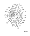
- FIG 9 is an overhead plan view of the pour connector.
- FIG. 10 is a vertical sectional view of the pour connector taken along line X-X of FIG. 9 .
- FIG. 11 is an explanatory view, which illustrates flows of a lubricant poured into a pour passage of the pour connector and discharged gases. As shown in FIGS.
- a pour port 105 of a cylinder head cover 103 of an engine 101 is upwardly obliquely opened.
- a seat portion 106 formed around the pour port 105 is inclined by an angle ⁇ 3 with respect to a horizontal line.
- the pour connector 110 is composed of a substantially cylindrically-shaped body portion 111 having a pour passage 140 therein, a lower end connecting portion 120 that is integrally formed in a lower end of the body portion 111 and that can be connected to the pour port 105 of the cylinder head cover 103 while a lower end opening of the pour passage 140 is aligned with the pour port 105, and a cap fitting portion 130 that is integrally formed in an upper end of the body portion 111 and that can be fitted with a cap (not shown) for openably closing an upper end opening of the pour passage 140.
- a lower surface of the lower end connecting portion 120 has the same inclination angle as the seat portion 106, so as to be inclined by the angle ⁇ 3 with respect to the horizontal line.
- a guide piece 150 is integrally formed in the body portion 111 so as to be positioned between an upper end and a lower end of the pour passage 140 of the body portion 111.
- the guide piece 150 protrudes from a portion of an inner circumferential wall surface 155 of the pour passage 140 toward the center thereof and has a guide surface 151 formed in an upper surface thereof which surface is directed to the center of the pour passage 140 and is downwardly inclined, thereby partially closing the pour passage 140.
- the guide piece 150 protrudes from a position of the inner circumferential wall surface 155 of the pour passage 140 over a range of a predetermined angle ⁇ 4 (e.g., an angle of approximately 180 to 220 degrees) as shown in FIG. 9 .
- a predetermined angle ⁇ 4 e.g., an angle of approximately 180 to 220 degrees
- the guide piece 150 that protrudes from the inner circumferential wall surface 155 of the pour passage 140 toward the center thereof may preferably be formed such that its projecting edge 153 does not extend beyond the center of the pour passage 140.
- the guide surface 151 formed in the upper surface of the guide piece 150 is defined by a portion of an inner surface of a cone.
- a drop guide surface 152 formed between a portion closer to the projecting edges of the guide surface 151 of the guide piece 150 and the projecting edge 153 is a drop guide surface 152 that is sharply inclined than the guide surface 151.
- the projection edge 153 of the drop guide surface 152 is shaped to a concave arc (an arc centered at the center of the pour passage 140) in a plan view.
- a gas guide portion 156 is formed in a portion of the pour passage 140 in which the guide piece 150 is formed.
- This gas guide portion 156 is defined by a lower surface 154 of the guide piece 150 and the inner circumferential wall surface 155 of the pour passage 140.
- the projection edge 153 of the guide piece 150 is positioned below its base portion on the inner circumferential wall surface 155 of the pour passage 140 by a distance corresponding to a dimension H in the gravitational direction, so that the lubricant (engine oil) poured into the pour passage 140 can flow toward the center while it is guided by the guide surface 151.
- the gas guide portion 156 is positioned above the projection edge 153 of the guide piece 150 in the gravitational direction, so that gases in the cylinder head cover 103 can be discharged from circumferential ends of the gas guide portion 156 upwardly, i.e., in a direction opposite to a pour direction of the lubricant.
- the lower end connecting portion 120 is formed with a lower tapered hole portion 144 and a lower end hole portion 145 that respectively constitute an outlet port 140b of the pour passage 140 of the body portion 111.
- a cap receiving portion 131 that constitutes an inlet port 140a of the pour passage 140 of the body portion 111.
- Female threads 132 are formed in an inner circumferential wall surface of the cap receiving portion 131, so that male threads formed in the cap (not shown) can be screwed therein.
- an upper tapered cylinder portion 143 formed between the cap fitting portion 130 and the body portion 111 is an upper tapered cylinder portion 143 having an upper tapered hole portion 142. This upper tapered hole portion is communicated with the cap receiving portion 131 at an upper end thereof and which is gradually reduced toward a lower end thereof and is communicated with the pour passage 140 at the lower end.
- a plurality of reinforcing ribs 112 that are circumferentially spaced at predetermined intervals and vertically extend from the upper tapered cylinder portion 143 to the lower end of the body portion 111.
- recesses 126 are formed in an outer circumferential side surface of the lower end connecting portion 120 in order to prevent formation of bending and shrinking due to uneven thickness during resin molding. Also, the recesses 126 may preferably maintain flatness of the lower surface of the lower end connecting portion 120.
- the lower surface of the lower end connecting portion 120 is formed with an annular groove 124. This annular groove circumferentially extends around the lower end opening of the pour passage 140 and is shaped to receive a seal member 125 (for example, an O-ring formed from elastic materials) therein.
- the pour connector 110 of the second embodiment is constructed as described above. Therefore, the second embodiment may substantially have the same functions and effects as the first embodiment. That is, in the second embodiment, when the lubricant is poured from the upper end opening of the inlet port 140a of the pour passage 140 of the pour connector 110, the lubricant can be smoothly poured and guided while it is restrained from interfering with the discharged gases from the cylinder head cover 103.
- the guide piece 150 protrudes from a position of the inner circumferential wall surface 155 of the pour passage 140 over the range of the predetermined angle ⁇ 4 (e.g., the angle of approximately 180 to 220 degrees) as shown in FIG. 9 . Therefore, the pour passage 140 may have an increased opening area at the portion in which the guide piece 150 exists. As a result, the lubricant can be poured in increased amounts per unit time.
- a lower surface of the cap fitting portion 130 has the same inclination angle as the seat portion 106 of the cylinder head cover 103, so as to be inclined by the angle ⁇ 3 with respect to the horizontal line.
- This structure is suitable for a case in which the pour port 5 disposed in a central portion of the seat portion 106 of the cylinder head cover 103 is upwardly obliquely opened. That is, when the pour port 105 of the cylinder head cover 103 is upwardly obliquely opened, the pour connector 110 can be attached thereto while the lower end connecting portion 120 thereof is inclined, so that the upper end opening of the inlet port 140a of the pour passage 140 can be directed upwardly. This may lead to an easy pouring operation of the lubricant.
- FIG. 12 is a front view of a pour structure of a cylinder head cover according to the third embodiment of the present invention.
- FIG. 13 is a vertical sectional view of the pour structure of the cylinder head cover.
- the cylinder head cover 3 and the body portion of the pour connector of the first embodiment are integrally formed as a unit. That is, the substantially cylindrically-shaped body portion 11 having the pour passage 40 therein is integrally formed (integrally molded) in an upper portion of the cylinder head cover 3. Because other structures of the third embodiment are the same as the first embodiment, elements that are the same in the first embodiment will be identified by the same reference numerals and a description of such elements may be omitted.
- the pour structure 210 of the third embodiment when the lubricant is poured from the upper end opening of the pour passage 40, almost all of the lubricant flows toward the center of the pour passage 40 while it is guided by the guide surfaces 51 of the guide pieces 50. Thereafter, the lubricant flows down from the edges of the guide pieces 50 and is then poured into the cylinder head cover 3.
- the gases (air) in the cylinder head cover 3 are discharged from the pour passage 40 by an amount corresponding to a pour amount of the lubricant. At this time, a flow of the discharged gases is directed in a direction opposite to a pour direction of the lubricant.
- the lubricant does not enter the gas guide portions 56 that are positioned above the edges of the guide pieces 50 in the gravitational direction, the discharged gases flows from the gas guide portions 56 through the base side edges of the guide pieces 50 and the circumferential wall surface of the pour passage 40 without interfering with the lubricant flowing down along the central portion of the pour passage 40, so as to be discharged to the upper end opening of the pour passage 40.
- the lubricant can be smoothly poured and guided while it is restrained from interfering with the discharged gases from the cylinder head cover 3.
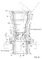
- FIG. 14 is a vertical sectional view of a pour structure of a cylinder head cover according to a fourth embodiment of the present invention.
- FIG. 15 is a side view of a proximal end guide member.
- FIG. 16 is a transverse sectional view of the proximal end guide member taken along line XVI-XVI of FIG. 15 .
- the pour connector 310 is composed of a connector main body 310a and a proximal end guide member 60.
- the connector main body 310a integrally includes the body portion 11, the lower end connecting portion 20 and the cap fitting portion 30 each of which has the same construction as the first embodiment and is integrally formed by injection molding of thermoplastic synthetic resinous materials.
- the proximal end guide member 60 is separated from the connector main body 310a and is integrally formed by injection molding of compatible thermoplastic synthetic resinous materials. That is, in the fourth embodiment, a coupling recess 27 having a diameter greater than the outlet port 40b ( FIG 5 ) of the first embodiment is formed in an inner circumference of a lower end portion of the lower end connecting portion 20 that constitutes the lower end opening (corresponding to the outlet port) of the pour passage 40 of the body portion 11.
- the proximal end guide member 60 that is capable of preventing the lubricant (liquid) from spattering is coupled to the coupling recess 27.
- the proximal end guide member 60 is formed into a bottomed cylindrical shape, so as to have a circumferential wall portion 61 and a bottom wall portion 62 that define an inner space 60a communicated with the lower end opening of the pour passage 40.
- the circumferential wall portion 61 has an outer diameter that is somewhat smaller than an inner diameter of the pour port 5 of the cylinder head cover 3, so as to be fitted into the pour port 5.
- formed in the circumferential wall portion 61 is an open hole 63 through which the inner space 60a is communicated with an interior of the cylinder head cover 3.
- the open hole 63 is formed in substantially a lower half portion of the circumferential wall portion 61 (in a portion between a vertical mid portion and a lower end portion) and is formed so as to have an opening width corresponding to approximately 1/4 to 1/3 of an entire circumference of the circumferential wall portion 61.
- a closure portion 64 and a flange 65 are integrally formed in an outer circumference of an upper end portion of the circumferential wall portion 61 of the proximal end guide member 60.
- the closure portion 64 has a diameter greater than the pour port 5 of the cylinder head cover 3 and is shaped to close the pour port 5.
- the flange 65 is positioned adjacent to an upper end of the closure portion 64 and has a diameter greater than the closure portion 64 and somewhat smaller than the coupling recess 27.
- the flange 65 of the proximal end guide member 60 is fitted into the coupling recess 27 of the lower end connecting portion 20.
- an upper surface of the flange 65 is integrally bonded to a bottom surface 28 of the coupling recess 27 via adhesives, high-frequency fusion-bonding, ultrasonic fusion-bonding or other such means, so as to be fixed thereto.
- a lower surface of the lower end connecting portion 20 and a lower surface of the closure portion 64 of the proximal end guide member 60 are shaped so as to flush with each other and to closely contact an upper end surface of the pour port 5 of the cylinder head cover 3 when the flange 65 of the proximal end guide member 60 are integrally connected to the coupling recess 27 of the lower end connecting portion 20 ( FIG. 14 ).
- annular groove 24a is defined by an inner circumferential surface of the coupling recess 27 of the lower end connecting portion 20, a lower surface of the flange 65 of the proximal end guide member 60 and an outer circumferential surface of the closure portion 64.
- the seal member e.g., an O-ring formed of an elastic material
- the pour connector 310 can be reliably sealed with respect to the pour port 5 of the cylinder head cover 3.
- the pour structure 310 of the fourth embodiment is constructed as described above. Therefore, in a condition in which the pour connector 310 is connected to the pour port 5 of the cylinder head cover 3 via the lower end connecting portion 20, when the lubricant is poured from the upper end opening of the pour passage 40, almost all of the lubricant flows toward the center of the pour passage 40 while it is guided by the guide surfaces 51 of the guide pieces 50. Thereafter, the lubricant flows down from the edges of the guide pieces 50. Thereafter, the lubricant flows through the lower end opening of the pour passage 40 into the inner space 60a of the proximal end guide member 60.
- the lubricant flows along the bottom wall portion 62 of the proximal end guide member 60 and is then poured into the cylinder head cover 3 via the open hole 63 of the circumferential wall portion 61.
- the gases (air) in the cylinder head cover 3 are introduced into the inner space 60a via the open hole 63 of the proximal end guide member 60 by an amount corresponding to a pour amount of the lubricant, and are then discharged from the pour passage 40 similar to the first embodiment.
- the lubricant can be smoothly poured and guided while it is restrained from interfering with the discharged gases from the cylinder head cover 3.
- the spattered lubricant in the engine (including the cylinder head cover 3) is spattered toward the pour connector 310, the spattered lubricant impinges against a lower surface of the bottom wall portion 62 and an outer circumferential surface of the circumferential wall portion 61 of the proximal end guide member 60, so as to be dropped. As a result, the spattered lubricant can be further effectively prevented from entering the pour passage 40 via the inner space 60a of the proximal end guide member 60.
- the spattered lubricant Even if a portion of the spattered lubricant is spattered toward the lower end opening of the pour passage 40 via the inner space 60a of the proximal end guide member 60 through the open hole 63 thereof, the spattered lubricant impinges against the lower sides of the guide pieces 50 in the pour passage 40, so as to be prevented from being spattered upwardly in the pour passage 40. That is, in the fourth embodiment, due to the proximal end guide member 60 disposed at the lower end opening of the pour passage 40 and the guide pieces 50 in the pour passage 40, the lubricant can be doubly prevented from spattering.
- the coupling recess 27 is formed in the inner circumference of the lower end portion of the lower end connecting portion 20.
- the flange 65 that is integrally bonded to the bottom surface of the coupling recess 27 is integrally formed in the outer circumference of the upper end portion of the proximal end guide member 60. Therefore, the upper surface of the flange 65 of the proximal end guide member 60 can be stably secured to the bottom surface 28 of the coupling recess 27 of the lower end connecting portion 20 via adhesives or fusion-bonding. That is, in the fourth embodiment, the connector main body 310a and the proximal end guide member 60 are respectively formed from the compatible thermoplastic synthetic resinous materials.
- the upper surface of the flange 65 of the proximal end guide member 60 can be reliably and firmly bonded and connected to the bottom surface 28 of the coupling recess 27 of the lower end connecting portion 20 of the connector main body 310a via adhesives, high-frequency fusion-bonding, ultrasonic fusion-bonding or other such means.
- the pour port 5 can be closed by the closure portion 64 that is formed in the outer circumference of the upper end portion of the circumferential wall portion 61 of the proximal end guide member 60 and has a diameter greater than the pour port 5 of the cylinder head cover 3. Therefore, the proximal end cover member 60 can be prevented from falling into the cylinder head cover 3.
- the annular groove 24a corresponding to the seal member 25 is defined by the inner circumferential surface of the coupling recess 27, the lower surface of the flange 65 of the proximal end guide member 60 and the outer circumferential surface of the closure portion 64.
- the seal member 25 can be easily fitted into and retained in the annular groove 24a. Therefore, the lubricant can be reliably prevented from leaking from the clearance between the lower end connecting portion 20 of the pour connector 10 and the cylinder head cover 3.
- the present invention is not limited to the embodiments described above.
- the pour port 5 (105) of the cylinder head cover 3 (103) is exemplified as the pour port of the liquid container
- the present invention can be carried out if the liquid container is a tank, a container or the like that is used to reserve or store a liquid such as water, oil, chemicals and medical solutions.
Landscapes
- Engineering & Computer Science (AREA)
- Mechanical Engineering (AREA)
- General Engineering & Computer Science (AREA)
- Chemical & Material Sciences (AREA)
- Sustainable Development (AREA)
- Sustainable Energy (AREA)
- Life Sciences & Earth Sciences (AREA)
- Combustion & Propulsion (AREA)
- Transportation (AREA)
- Lubrication Details And Ventilation Of Internal Combustion Engines (AREA)
- Cylinder Crankcases Of Internal Combustion Engines (AREA)
- Closures For Containers (AREA)
- Filling Or Discharging Of Gas Storage Vessels (AREA)
- Lubrication Of Internal Combustion Engines (AREA)
Abstract
Description
- The present invention relates to a pour connector that is connected to a pour port of a liquid container, e.g., a cylinder head cover of an engine, a tank and the like so as to pour a liquid into the liquid container, and a pour structure.
- Generally, the cylinder head cover of an engine is provided with a pour port for pouring a lubricant (engine oil) therethrough, and this pour port is constructed to be closed by an opening/closing cover (cap) that can be detachably screwed thereinto.
Further, a pour port structure for a cylinder head cover is known (see, for example, Patent Document 1). In this structure, in order to prevent the lubricant from spattering outward via the pour port, a protector is disposed inside of the cylinder head cover at a portion positioned below the pour port. One end portion of the protector is fixed to the portion by clamping, and a distal end portion (free end portion) thereof is provided with a guard piece arranged in a step-like pattern, which guard piece is directed in such a direction that crosses a direction of a pour passage of the lubricant.
Patent Document 1: Japanese Laid-Open Patent Publication No.07-293220 - When the lubricant is poured via the pour port of the cylinder head cover, gases (air) in the cylinder head cover is discharged via the pour port by an amount corresponding to a pour amount of the lubricant.
At this time, within the pour passage, a flow of the discharged gases is directed in a direction opposite to a pour direction of the lubricant. Further, because an area through which the discharged gases flow is identical to an area through which the lubricant is poured, a flow of the lubricant in a pour direction thereof is disturbed by the discharged gases and as a result, the lubricant cannot be poured smoothly. - In view of the above-mentioned problem, it is an object of the present invention to provide a pour connector of a liquid container in which when a liquid is poured via a pour port of a liquid container such as a cylinder head cover of an engine and a tank, the liquid can be smoothly poured and guided while it is avoided from interfering with the discharged gases, and a pour structure.
- In order to achieve the above-mentioned object, a pour connector of a liquid container of the present invention is directed to a pour connector that is connected to a pour port of a liquid container such as a cylinder head cover of an engine and a tank so as to pour a liquid into said liquid container, which includes a cylindrically-shaped body portion having a pour passage therein, a lower end connecting portion that is integrally formed in a lower end of said body portion and that can be connected to the pour port of said liquid container while a lower end opening of said pour passage is aligned with the pour port, and a cap fitting portion that is integrally formed in an upper end of said body portion and that can be fitted with a cap for openably closing an upper end opening of said pour passage. A guide piece is integrally formed in the body portion so as to be positioned between an upper end and a lower end of the pour passage of said body portion. The guide piece protrudes from a portion of an inner circumferential wall surface of said pour passage toward the center thereof and has a guide surface formed in an upper surface thereof which surface is directed to the center of said pour passage and is downwardly inclined, thereby partially closing said pour passage. A gas guide portion is formed in a portion of said pour passage in which said guide piece is formed. The gas guide portion is defined by a lower surface of said guide piece and the inner circumferential wall surface of said pour passage. When said pour connector is connected to the pour port of said liquid container to use the same, a projection edge of said guide piece is positioned below its base portion on the inner circumferential wall surface of said pour passage in the gravitational direction, so that the liquid poured into said pour passage can flow toward the center while it is guided by said guide surface, whereas said gas guide portion is positioned above the projection edge of said guide piece in the gravitational direction, so that gases in said container can be discharged from circumferential ends of said gas guide portion in a direction opposite to said pour direction.
- According to the structure described above, in a condition in which the pour connector is connected to the pour port of the liquid container via the lower end connecting portion, when the liquid is poured from the upper end opening of the pour passage of the pour connector, almost all of the liquid flows toward the center of the pour passage while it is guided by the guide surface of the guide piece and then flows down from the edge of the guide piece so as to be poured into the liquid container.
Conversely, when the liquid is poured into the liquid container, the gases (air) in the liquid container are discharged from the pour passage by an amount corresponding to a pour amount of the liquid.
At this time, a flow of the discharged gases is directed in a direction opposite to a pour direction of the liquid. However, since the liquid does not enter the gas guide portion that is positioned above the edge of the guide piece in the gravitational direction, the discharged gases flow from the gas guide portion through base side edges of the guide piece and the circumferential wall surface without interfering with the liquid flowing down along the central portion of the pour passage, so as to be discharged to the upper end opening of the pour passage.
Thus, when the liquid is poured from the upper end opening of the pour passage of the pour connector that is connected to the pour port of the liquid container, the liquid can be smoothly poured and guided while it is restrained from interfering with the discharged gases from the liquid container.
Further, in a condition in which the liquid container poured with the liquid is in use, for example, in a condition in which an engine is embodied as the liquid container and is operated while the pour connector is connected to the pour port of the cylinder head cover, when a lubricant as the liquid in a cylinder head and the cylinder head cover is spattered toward the lower end opening of the pour passage of the pour connector, the lubricant impinges against the lower side of the guide piece, so as to be prevented from being spattered upwardly in the pour passage.
Further, since the guide piece is integrally formed in the circumferential wall surface of the pour passage of the pour connector, it is possible to save time consuming work of separately forming the guide piece and attaching the same thereto. Also, it is not necessary to form a seat portion in the circumferential wall surface of the pour passage of the pour connector for attaching the separately formed guide piece thereto. - Further, the inner circumferential wall surface of the pour passage may preferably be formed into a tapered-shape that is gradually enlarged from a boundary defined along the base portion of the guide piece toward the upper end opening and toward the lower end opening. In such a structure, for example, after a cavity of a molding tool having upper and lower core molds corresponding to the pour passage is filled with synthetic resinous materials so as to integrally form the pour connector, the upper and lower core molds can be easily released from the pour passage of the pour connector.
- Further, the guide piece that protrudes from the inner circumferential wall surface of the pour passage toward the center thereof may preferably be formed such that the projecting edge does not extend beyond the center of said pour passage.
In this structure, in the portion of the pour passage in which the guide piece is formed, it is possible to sufficiently make a space through which the liquid flows down along the center of the pour passage and a space through which the discharged gases flow, and to effectively prevent interference of the liquid and the discharged gases. Thus, the liquid can be further smoothly poured. - Further, the guide piece may preferably protrudes from a single position of the inner circumferential wall surface of the pour passage.
In this structure, the pour passage may have an increased opening area at the portion in which the guide piece exists. As a result, the liquid can be poured in increased amounts at a time. - Further, the guide piece may preferably protrude from two positions of the inner circumferential wall surface of the pour passage which positions are spaced apart from each other in a circumferential direction thereof and are opposed to each other.
In this structure, the guide pieces are formed in both sides of the pour passage such that the liquid can be led down and guided toward the center. Therefore, it is possible to suitably avoid interference between the liquid and the discharged gases. Further, in a use condition of the liquid container in which the liquid is poured, the spattered liquid is more likely to impinge against the lower surfaces of the guide pieces. This may have an increased effects on spattering prevention of the liquid.
Further, because the guide pieces are opposed to each other, when the liquid pour connector is attached to the liquid container, it can be attached thereto without checking directions in which the guide pieces protrude. - Further, the guide surface formed in the upper surface of the guide piece may preferably be defined by a portion of an inner surface of a cone.
In this structure, the liquid poured into the pour passage can be suitably led down and guided toward the center by the guide surface of the guide piece that is defined by a portion of the inner surface of the cone. - Further, the projection edge of the guide piece may preferably be shaped to a concave arc.
In this structure, the liquid poured into the pour passage can be suitably led down from the projection edge of the guide piece that is shaped to the concave arc. In addition, it is possible to suitably avoid interference between the liquid and the discharged gases. - Further, attachment portions for attaching the pour connector to the liquid container may preferably be integrally formed in a plurality of portions of an outer circumference of the lower end connecting portion so as to be radially outwardly projected.
In this structure, the lower end connecting portion of the pour connector can be stably attached to the liquid container via a plurality of attachment portions. - Further, a lower surface of the lower end connecting portion may preferably be formed with an annular groove that circumferentially extends around the lower end opening of the pour passage and is shaped to receive a seal member therein.
In this structure, when the pour connector is attached to the liquid container while the seal member is fitted in the annular groove of the lower end connecting portion thereof, the lower end connecting portion of the pour connector can be sealed with respect to the liquid container, thereby preventing the liquid from leaking from a space between the lower end connecting portion of the pour connector and the liquid container. - Further, the pour passage may preferably be formed so as to have a center line that is formed by a straight line.
This structure is suitable for a case in which the pour port of the liquid container is opened upwardly. That is, when the pour port of the liquid container is opened upwardly, the pour connector can be perpendicularly attached thereto, so that the upper end opening of the pour passage can be directed upwardly. This may lead to an easy pouring operation of the liquid. - Further, the pour passage may preferably be formed such that a center line thereof is angled at a predetermined angle at a position corresponding to the base portion of the guide piece.
This structure is suitable for a case in which the pour port on the liquid container is upwardly obliquely opened. That is, when the pour port of the liquid container is upwardly obliquely opened, the pour connector can be attached thereto while the lower end connecting portion thereof is inclined, so that the upper end opening of the pour passage can be directed upwardly. This may lead to an easy pouring operation of the liquid. - Further, a recess may preferably be formed in an outer circumferential side surface of the lower end connecting portion.
In this structure, formation of shrinking during resin molding can be prevented by the recess of the outer circumferential side surface of the lower end connecting portion, thereby preventing distortion of the lower end connecting portion caused by the shrinking during the resin molding. - Further, a bottomed-cylindrical shaped proximal end guide member having an inner space communicated with the lower end opening of the pour passage may preferably be provided to an inner circumference of a lower end portion of the lower end connecting portion. Also, a circumferential wall portion of the proximal end guide member may preferably be formed with an open hole through which the inner space is communicated with an interior of the liquid container.
In this structure, in a condition in which the pour connector is connected to the pour port of the liquid container via the lower end connecting portion, when the liquid is poured from the upper end opening of the pour passage of the pour connector, almost all of the liquid flows toward the center of the pour passage while it is guided by the guide surface of the guide piece. Thereafter, the liquid flows down from the edge of the guide piece. Thereafter, the liquid flows through the lower end opening of the pour passage into the inner space of the proximal end guide member, and is then poured into the liquid container via the open hole of the proximal end guide member.
Conversely, when the liquid is poured into the liquid container, the gases (air) in the liquid container are introduced into the inner space via the open hole of the proximal end guide member by an amount corresponding to a pour amount of the liquid, and are then discharged from the pour passage.
In addition, in a condition in which the liquid container poured with the liquid is in use, for example, in a condition in which an engine is embodied as the liquid container and is operated while the pour connector is connected to the pour port of the cylinder head cover, when a lubricant as the liquid in a cylinder head and the cylinder head cover is spattered toward the pour connector, the spattered lubricant impinges against a lower surface of the bottom wall portion and an outer circumferential surface of the circumferential wall portion of the proximal end guide member, so as to be dropped. As a result, the spattered lubricant can be prevented from entering the pour passage via the inner space of the proximal end guide member.
Even if a portion of the spattered lubricant is spattered toward the lower end opening of the pour passage via the inner space of the proximal end guide member through the open hole thereof, the spattered lubricant impinges against the lower side of the guide piece in the pour passage, so as to be prevented from being spattered upwardly in the pour passage.
That is, due to the proximal end guide member disposed at the lower end opening of the pour passage and the guide piece in the pour passage, the lubricant can be doubly prevented from spattering. - Further, a coupling recess may preferably be formed in an inner circumference of a lower end portion of the lower end connecting portion. Also, a flange that is integrally bonded to a bottom surface of said coupling recess may preferably be formed in an outer circumference of an upper end portion of the proximal end guide member. In this structure, the flange formed in the outer circumference of the upper end portion of the proximal end guide member can be stably secured to the bottom surface of the coupling recess of the lower end connecting portion via adhesives or fusion-bonding.
For example, if a connector main body and the proximal end guide member are respectively formed from compatible thermoplastic synthetic resinous materials, the flange formed in the outer circumference of the upper end portion of the proximal end guide member can be reliably and firmly bonded and connected to the bottom surface of the coupling recess of the lower end connecting portion via adhesives, high-frequency fusion-bonding, ultrasonic fusion-bonding or other such means. - A pour structure of a cylinder head cover of the present invention is directed to a pour structure for pouring a lubricant into a cylinder head cover of an engine, which includes a cylindrically-shaped body portion integrally formed in an upper portion of the cylinder head cover and having a pour passage therein, and a cap fitting portion that is integrally formed in an upper end of said body portion and that can be fitted with a cap for openably closing an upper end opening of said pour passage. A guide piece is integrally formed in the body portion so as to be positioned between an upper end and a lower end of the pour passage of said body portion. The guide piece protrudes from a portion of an inner circumferential wall surface of said pour passage toward the center thereof and has a guide surface formed in an upper surface thereof which surface is directed to the center of said pour passage and is downwardly inclined, thereby partially closing said pour passage. A gas guide portion is formed in a portion of said pour passage in which said guide piece is formed. The gas guide portion is defined by a lower surface of said guide piece and the inner circumferential wall surface of said pour passage. A projection edge of said guide piece is positioned below its base portion on the inner circumferential wall surface of said pour passage in the gravitational direction, so that the lubricant poured into said pour passage can flow toward the center while it is guided by said guide surface, whereas said gas guide portion is positioned above the projection edge of said guide piece in the gravitational direction, so that gases in said cylinder head cover can be discharged from circumferential ends of said gas guide portion in a direction opposite to said pour direction.
- According to the structure described above, when the lubricant is poured from the upper end opening of the pour passage, almost all of the lubricant flows toward the center of the pour passage while it is guided by the guide surface of the guide piece and then flows down from the edge of the guide piece so as to be poured into the cylinder head cover.
When the lubricant is poured into the cylinder head cover, the gases (air) in the cylinder head cover are discharged from the pour passage by an amount corresponding to a pour amount of the lubricant.
At this time, a flow of the discharged gases is directed in a direction opposite to a pour direction of the lubricant. However, since the lubricant does not enter the gas guide portion that is positioned above the edge of the guide piece in the gravitational direction, the discharged gases flow from the gas guide portion through base side edges of the guide piece and the circumferential wall surface without interfering with the lubricant flowing down along the central portion of the pour passage, so as to be discharged to the upper end opening of the pour passage.
Thus, the lubricant can be smoothly poured and guided while it is restrained from interfering with the discharged gases from the cylinder head cover.
Further, when the lubricant in the cylinder head cover is spattered toward the lower end opening of the pour passage, the lubricant impinges against the lower side of the guide piece, so as to be prevented from being spattered upwardly in the pour passage.
Further, the substantially cylindrically-shaped body portion having the pour passage, the guide piece and the gas guide portion are integrally formed in the upper portion of the cylinder head cover. As a result, the number of components and the number of fabrication processes can be reduced. -
-
FIG 1 is a schematic perspective view of a pour connector according to a first embodiment of the present invention, which illustrates a condition in which it is connected to a pour port of a cylinder head cover of an engine. -
FIG. 2 is a front view of the pour connector in which a attachment portion thereof is partially cutaway. -
FIG. 3 is an overhead plan view of the pour connector. -
FIG. 4 is a bottom plan view of the pour connector. -
FIG 5 is a vertical sectional view of the pour connector taken along line V-V ofFIG. 3 . -
FIG. 6 is an explanatory view, which illustrates flows of a lubricant poured into a pour passage of the pour connector and discharged gases. -
FIG. 7 is a schematic perspective view of a pour connector according to a second embodiment of the present invention, which illustrates a condition in which it is connected to a pour port of a cylinder head cover of an engine. -
FIG. 8 is a front view of the pour connector. -
FIG. 9 is an overhead plan view of the pour connector. -
FIG. 10 is a vertical sectional view of the pour connector taken along line X-X ofFIG. 9 . -
FIG. 11 is an explanatory view, which illustrates flows of a lubricant poured into a pour passage of the pour connector and discharged gases. -
FIG. 12 is a front view of a pour structure of a cylinder head cover according to a third embodiment of the present invention. -
FIG. 13 is a vertical sectional view of the pour structure of the cylinder head cover. -
FIG. 14 is a vertical sectional view of a pour structure of a cylinder head cover according to a fourth embodiment of the present invention. -
FIG. 15 is a side view of a proximal end guide member. -
FIG. 16 is a transverse sectional view of the proximal end guide member taken along line XVI-XVI ofFIG. 15 . -
- 3, 103
- cylinder head cover (container)
- 5, 105
- pour port
- 10, 110, 210, 310
- pour connector
- 11, 111
- body portion
- 20, 120
- lower end connecting portion
- 21, 121
- attachment portion
- 24, 124
- annular groove
- 27
- coupling recess
- 28
- bottom surface
- 30, 130
- cap fitting portion
- 35, 135
- cap
- 40, 140
- pour passage
- 40a, 140a
- inlet port
- 40b, 140b
- outlet port
- 50, 150
- guide piece
- 51, 151
- guide surface
- 53, 153
- projection edge
- 55, 155
- inner circumferential wall surface
- 56, 156
- gas guide portion
- 60
- proximal end guide member
- 61
- circumferential wall portion
- 62
- bottom wall portion
- 63
- open hole
- 65
- flange
- Next, the best mode for carrying out the present invention will be described based upon embodiments.
- A first embodiment of the present invention will be described with reference to
FIGS. 1 to 6 .
FIG. 1 is a schematic perspective view of a pour connector according to the first embodiment of the present invention, which illustrates a condition in which it is connected to a pour port of a cylinder head cover of an engine.FIG. 2 is a front view of the pour connector in which a attachment portion thereof is partially cutaway.FIG. 3 is an overhead plan view of the pour connector.FIG. 4 is a bottom plan view of the pour connector.FIG. 5 is a vertical sectional view of the pour connector taken along line V-V ofFIG. 3 .FIG. 6 is an explanatory view, which illustrates flows of a lubricant poured into a pour passage of the pour connector and discharged gases.
As shown inFIGS. 1 and2 , in the first embodiment, exemplified is a pourconnector 10 that is connected to a pourport 5 of acylinder head cover 3 of an engine 1 as a pour port of a liquid container. The pourconnector 10 is integrally formed as a unit by injection molding of synthetic resinous materials. - As shown in
FIGS. 2 to 5 , the pourconnector 10 is composed of a substantially cylindrically-shapedbody portion 11 having a pourpassage 40 therein, a lowerend connecting portion 20 that is integrally formed in a lower end of thebody portion 11 and that can be connected to the pour port of the liquid container while a lower end opening of the pourpassage 40 is aligned with the pour port, and a capfitting portion 30 that is integrally formed in an upper end of thebody portion 11 and that can be fitted with acap 35 for openably closing an upper end opening of the pourpassage 40.
That is, in the first embodiment, as shown inFIG. 5 , the lowerend connecting portion 20 is formed with a lowertapered hole portion 44 and a lowerend hole portion 45 that respectively constitute anoutlet port 40b of the pourpassage 40 of thebody portion 11. Further, the lowertapered hole portion 44 is communicated with a lower end portion of the pourpassage 40 at an upper end thereof and has a tapered-shape that is gradually enlarged toward a lower end thereof. Also, the lowerend hole portion 45 is communicated with the lower end of the lowertapered hole portion 44. - As shown in
FIG. 5 , formed in the capfitting portion 30 is acap receiving portion 31 that constitutes aninlet port 40a of the pourpassage 40 of thebody portion 11.Female threads 32 are formed in an inner circumferential wall surface of thecap receiving portion 31, so thatmale threads 38 formed in an outer circumferential surface of aninsertion portion 37 of thecap 35 can be screwed therein. As shown by chain double-dashed lines inFIG. 2 , thecap 35 has an enlarged diametercap plate portion 36 and an reduceddiameter insertion portion 37 that integrally protrudes from the center of a lower surface of thecap plate portion 36. Themale threads 38 are formed in the outer circumferential surface of theinsertion portion 37. - As shown in
FIG 5 , formed between the capfitting portion 30 and thebody portion 11 is an uppertapered cylinder portion 43 having an uppertapered hole portion 42. The upper taperedportion 42 is communicated with thecap receiving portion 31 at an upper end thereof and is gradually reduced toward a lower end thereof and is communicated with the pourpassage 40 at the lower end.
Further, the pourpassage 40 having theinlet port 40a positioned at its upper portion and theoutlet port 40b positioned at its lower portion is perpendicularly oriented and has a center line that is formed by a straight line (vertical line). - As shown in
FIGS. 3 to 5 , guidepieces 50 are integrally formed in thebody portion 11 so as to be positioned between an upper end and a lower end of the pourpassage 40 of thebody portion 11. Theguide pieces 50 protrude from a portion of an innercircumferential wall surface 55 of the pourpassage 40 toward the center thereof and have guide surfaces 51 formed in upper surfaces thereof each of which surfaces is directed to the center of the pourpassage 40 and is downwardly inclined, thereby partially closing the pourpassage 40.
Further, theguide pieces 50 that protrude from the innercircumferential wall surface 55 of the pourpassage 40 toward the center thereof may preferably be formed such that their projectingedges 53 do not extend beyond the center of the pourpassage 40.
In the first embodiment, theguide pieces 50 protrude from two positions of the innercircumferential wall surface 55 of the pourpassage 40 which positions are spaced apart from each other in a circumferential direction thereof and are opposed to each other, and are paired with each other. Further, the guide surfaces 51 formed in the upper surfaces of a pair ofguide pieces 50 are defined by a portion of an inner surface of a common cone.
In the first embodiment, as shown inFIG 5 , an inclination angle θ 1 of the guide surfaces 51 of theguide pieces 50 with respect to the vertical line may preferably be determined at approximately 120 degrees.
Further, formed between portions closer to the projecting edges of the guide surfaces 51 of theguide pieces 50 and the projectingedges 53 are drop guide surfaces 52 that are sharply inclined than the guide surfaces 51. As shown inFIG. 3 , each of the projection edges 53 of the drop guide surfaces 52 is shaped to a concave arc (an arc centered at the center of the pour passage 40) in a plan view. - Further, as shown in
FIG. 5 ,gas guide portions 56 are formed in portions of the pourpassage 40 in which theguide pieces 50 are formed. Thesegas guide portions 56 are defined bylower surfaces 54 of theguide pieces 50 and the innercircumferential wall surface 55 of the pourpassage 40.
Further, as shown inFIG 6 , when the pourconnector 10 is connected to the pourport 5 of thecylinder head cover 3 to use the same, the projection edges 53 of theguide pieces 50 are positioned below their base portions adjacent to the innercircumferential wall surface 55 of the pourpassage 40 by a distance corresponding to a dimension G in the gravitational direction, so that the lubricant (engine oil) poured into the pourpassage 40 can flow toward the center while it is guided by the guide surfaces 51. Conversely, thegas guide portions 56 are positioned above the projection edges 53 of theguide pieces 50 in the gravitational direction, so that gases in thecylinder head cover 3 can be discharged from circumferential ends of thegas guide portions 56 upwardly, i.e., in a direction opposite to a pour direction of the lubricant. - Further, in the first embodiment, the inner
circumferential wall surface 55 of the pourpassage 40 is formed into a tapered-shape that is gradually enlarged from a boundary defined along the base portions of theguide pieces 50 toward the upper end opening (an upper end opening of theinlet port 40a) and toward the lower end opening (a lower end opening of theoutlet port 40b).
That is, as shown inFIG. 5 , an inner diameter dimension of thecap receiving portion 31 is referred to as a dimension A. An inner diameter dimension of the upper end of thebody portion 11 is referred to as a dimension B. An inner diameter dimension of a portion of thebody portion 11 corresponding to the base portions of theguide pieces 50 is referred to as a dimension C. A distance dimension between the projection edges 53 of theguide pieces 50 is referred to as a dimension D. An inner diameter dimension of the lower end of thebody portion 11 is referred to as a dimension E. An inner diameter dimension of the lowerend hole portion 45 of the lowerend connecting portion 20 is referred to as a dimension F. These dimensions are determined so as to have a following relation:
- Further, as shown in
FIGS. 2 to 4 ,attachment portions 21 for attaching the pourconnector 10 to thecylinder head cover 3 are integrally formed in a plurality of portions (inFIG. 3 , two positions spaced at 180 degrees) of an outer circumference of the lowerend connecting portion 20 so as to be radially outwardly projected.
Through-holes 23 are formed in therespective attachment portions 21. Also, closely fitted in the through-holes 23 aremetal collars 22 each having a through bore into which male threads of aattachment bolt 28 is inserted, so that excessive stress can be prevented from generating in theattachment portions 21.
Further, in the first embodiment, as shown inFIG 3 , a line L2 connecting the centers of the through-holes 23 is determined so as to be positioned at an angle of θ 2 with respect to a line L1 that is parallel to a front-back direction of a vehicle and passes through the center of the pourpassage 40. Also, the twoguide pieces 50 are symmetrically formed with respect to a line L3 that is orthogonal to the line L1 and passes through the center of the pourpassage 40. - Further, in the first embodiment, as shown in
FIGS. 2 to 4 , formed in outer circumferential surfaces of the uppertapered cylinder portion 43 and thebody portion 11 are a plurality of reinforcingribs 12 that are circumferentially spaced at predetermined intervals and vertically extend from the uppertapered cylinder portion 43 to the lower end of thebody portion 11, so that thebody portion 11 is strengthened.
Further, as shown inFIGS. 4 and5 , recesses 26 and 27 are formed in an outer circumferential side surface and a lower surface of the lowerend connecting portion 20 in order to prevent formation of deforming and shrinking due to uneven thickness during resin molding. Also, therecesses end connecting portion 20.
Further, as shown inFIG. 6 , the lower surface of the lowerend connecting portion 20 is formed with anannular groove 24. Thisannular groove 24 circumferentially extends around the lower end opening of the pourpassage 40 and is shaped to receive a seal member 25 (for example, an O-ring formed from elastic materials) therein. - The pour
connector 10 of the first embodiment is constructed as described above.
Therefore, as shown inFIGS. 1 and2 , the lowerend connecting portion 20 of the pourconnector 10 is disposed on aseat portion 6 that is formed around the pourport 5 of thecylinder head cover 3, and the through bores of themetal collars 22 of theattachment portions 21 of the lowerend connecting portion 20 are aligned with female threads formed in theseat portion 6. Thereafter, theattachment bolts 28 are screwed into the female threads of theseat portion 6 through thecollars 22 of theattachment portions 21, so that theoutlet port 40b of the pourpassage 40 of the pourconnector 10 is aligned with the pourport 5 of thecylinder head cover 3 and is connected thereto.
As described above, in a condition in which the pourconnector 10 is connected to the pourport 5 of thecylinder head cover 3, as shown inFIG. 6 , thecap 35 is removed from thecap receiving portion 31 of the pourconnector 10. Thereafter, the lubricant is poured from the upper end opening of theinlet port 40a of the pourpassage 40.
Thus, almost all of the lubricant flows toward the center of the pourpassage 40 while it is guided by the guide surfaces 51 formed in the upper surfaces of theguide pieces 50. Thereafter, the lubricant flows down from the projection edges 53 of the drop guide surfaces 52 and is then poured into the engine 1 through thecylinder head cover 3 so as to be stored in an oil pan positioned at a lower portion of the engine 1. - Conversely, when the lubricant is poured into the
cylinder head cover 3, the gases (air) in thecylinder head cover 3 are discharged from theinlet port 40a of the pourpassage 40 by an amount corresponding to a pour amount of the lubricant.
At this time, a flow of the discharged gases is directed in a direction opposite to a pour direction of the lubricant. However, since the lubricant does not enter thegas guide portions 56 that are positioned above the projection edges 53 of theguide pieces 50 in the gravitational direction, the discharged gases flow from thegas guide portions 56 through base side edges of theguide pieces 50 and the innercircumferential wall surface 55 of the pourpassage 40 without interfering with the lubricant flowing down along the central portion of the pourpassage 40, so as to be discharged to the exterior via theinlet port 40a of the pourpassage 40. - As described above, when the lubricant is poured from the upper end opening of the
inlet port 40a of the pourpassage 40 of the pourconnector 10, the lubricant can be smoothly poured and guided while it is restrained from interfering with the discharged gases from thecylinder head cover 3.
Further, in a condition in which the engine 1 poured with the lubricant is operated, when the lubricant in the engine 1 (including the cylinder head cover 3) is spattered toward theoutlet port 40b of the pourpassage 40 of the pourconnector 10, the lubricant impinges against thelower surfaces 54 of theguide pieces 50, so as to be prevented from being spattered upwardly in the pourpassage 40.
Further, since theguide pieces 50 are integrally formed in the innercircumferential wall surface 55 of the pourpassage 40 of the pourconnector 10, it is possible to save time consuming work of separately forming theguide pieces 50 and attaching the same thereto. Also, it is not necessary to form seat portions (attachment portions) in the pourconnector 10 for attaching the separately formedguide pieces 50 thereto. - Further, in the first embodiment, the inner
circumferential wall surface 55 of the pourpassage 40 is formed into a tapered-shape that is gradually enlarged from the boundary defined along the base portions of theguide pieces 50 toward the upper end opening of theinlet port 40a and toward the lower end opening of theoutlet port 40b.
That is, as shown inFIG. 5 , the respective dimensions are determined so as to have the relation "A > B > C > D, and F > E." Therefore, for example, after a cavity of a molding tool having upper and lower core molds corresponding to the pourpassage 40 is filled with the synthetic resinous materials so as to integrally form the pourconnector 10, the upper and lower core molds can be easily released from the pourpassage 40 of the pourconnector 10. - Further, in the first embodiment, the
guide pieces 50 that protrude from the innercircumferential wall surface 55 of the pourpassage 40 toward the center thereof are formed such that their projectingedges 53 do not extend beyond the center of said pourpassage 40. Therefore, in the portion of the pourpassage 40 in which theguide pieces 50 are formed, it is possible to sufficiently make a space through which the lubricant flows down along the center of the pourpassage 40 and a space through which the discharged gases flow, and to effectively prevent interference of the lubricant and the discharged gases. Thus, the lubricant can be further smoothly poured. - Further, in the first embodiment, the
guide pieces 50 protrude from the two positions which are spaced apart from each other in a circumferential direction of the innercircumferential wall surface 55 of the pourpassage 40 and are opposed to each other, so that the lubricant can be led down and guided from both sides of the pourpassage 40 toward the center by both of theguide pieces 50. Therefore, it is possible to suitably avoid interference between the lubricant and the discharged gases. Further, in a use condition, for example, in a condition in which the vehicle is moved, the spattered lubricant is more likely to impinge against thelower surfaces 54 of theguide pieces 50. This may have an increased effects on spattering prevention of the lubricant.
Further, because theguide pieces 50 are opposed to each other, when the pourconnector 10 is attached to the pourport 5 of thecylinder head cover 3, it can be attached thereto without checking directions in which theguide pieces 50 protrude. - Further, in the first embodiment, because the guide surfaces 51 formed in the upper surfaces of the
guide pieces 50 are defined by a portion of the inner surface of the cone, the lubricant poured into the pourpassage 40 can be suitably led down and guided toward the center by the guide surfaces 51 of theguide pieces 50 that are defined by a portion of the inner surface of the cone. - Further, in the first embodiment, as shown in
FIG. 3 , the projection edges 53 of theguide pieces 50 are shaped to the concave arc in plan view. Therefore, the lubricant poured into the pourpassage 40 can be suitably led down from the projection edges 53 of theguide pieces 50 that are shaped to the concave arc. In addition, it is possible to suitably avoid interference between the lubricant and the discharged gases. - Further, in the first embodiment, the
attachment portions 21 for attaching the pourport 5 of thecylinder head cover 3 are integrally formed in a plurality of portions of the outer circumference of the lowerend connecting portion 20 so as to be radially outwardly projected. Therefore, the lowerend connecting portion 20 of the pourconnector 10 can be stably attached to thecylinder head cover 3 via a plurality ofattachment portions 21. - Further, in the first embodiment, as shown in
FIG. 6 , the lower surface of the lowerend connecting portion 20 is formed with theannular groove 24. Thisannular groove 24 circumferentially extends around the lower end opening of the pourpassage 40 and is shaped to receive theseal member 25 therein. Therefore, when the pourconnector 10 is attached to thecylinder head cover 3 while theseal member 25 is fitted in theannular groove 24 of the lowerend connecting portion 20 thereof, the lowerend connecting portion 20 of the pourconnector 10 can be sealed with respect to thecylinder head cover 3, thereby preventing the lubricant from leaking from a space between the lowerend connecting portion 20 of the pourconnector 10 and thecylinder head cover 3. - Further, in the first embodiment, because the pour
passage 40 is formed so as to have a center line that is formed by a straight line, it is suitable for a case in which the pourport 5 of thecylinder head cover 3 is opened upwardly. That is, when the pourport 5 of thecylinder head cover 3 is opened upwardly, the pourconnector 10 can be perpendicularly attached thereto, so that the upper end opening of theinlet port 40a of the pourpassage 40 can be directed upwardly. This may lead to an easy pouring operation of the lubricant. - Further, in the first embodiment, as shown in
FIGS. 4 and5 , because therecesses 26 are formed in the outer circumferential side surface and the lower surface of the lowerend connecting portion 20, the formation of the shrinking during the resin molding can be prevented by therecesses 26 of the outer circumferential side surface of the lowerend connecting portion 20, thereby preventing distortion of the lowerend connecting portion 20 caused by the shrinking during the resin molding. - Next, a pour connector according to a second embodiment of the present invention will be described with reference to
FIGS. 7 to 11 .
FIG. 7 is a schematic perspective view of a pour connector according to the second embodiment of the present invention, which illustrates a condition in which it is connected to a pour port of a cylinder head cover of an engine.FIG 8 is a front view of the pour connector.FIG 9 is an overhead plan view of the pour connector.FIG. 10 is a vertical sectional view of the pour connector taken along line X-X ofFIG. 9 .FIG. 11 is an explanatory view, which illustrates flows of a lubricant poured into a pour passage of the pour connector and discharged gases.
As shown inFIGS. 7 and8 , in the second embodiment, a pourport 105 of acylinder head cover 103 of anengine 101 is upwardly obliquely opened. Also, aseat portion 106 formed around the pourport 105 is inclined by anangle θ 3 with respect to a horizontal line. - On the other hand, as shown in
FIGS. 7 to 10 , the pourconnector 110 is composed of a substantially cylindrically-shapedbody portion 111 having a pourpassage 140 therein, a lowerend connecting portion 120 that is integrally formed in a lower end of thebody portion 111 and that can be connected to the pourport 105 of thecylinder head cover 103 while a lower end opening of the pourpassage 140 is aligned with the pourport 105, and a capfitting portion 130 that is integrally formed in an upper end of thebody portion 111 and that can be fitted with a cap (not shown) for openably closing an upper end opening of the pourpassage 140.
Further, a lower surface of the lowerend connecting portion 120 has the same inclination angle as theseat portion 106, so as to be inclined by theangle θ 3 with respect to the horizontal line. - As shown in
FIGS. 9 and10 , aguide piece 150 is integrally formed in thebody portion 111 so as to be positioned between an upper end and a lower end of the pourpassage 140 of thebody portion 111. Theguide piece 150 protrudes from a portion of an innercircumferential wall surface 155 of the pourpassage 140 toward the center thereof and has aguide surface 151 formed in an upper surface thereof which surface is directed to the center of the pourpassage 140 and is downwardly inclined, thereby partially closing the pourpassage 140.
In the second embodiment, theguide piece 150 protrudes from a position of the innercircumferential wall surface 155 of the pourpassage 140 over a range of a predetermined angle θ 4 (e.g., an angle of approximately 180 to 220 degrees) as shown inFIG. 9 . Further, theguide piece 150 that protrudes from the innercircumferential wall surface 155 of the pourpassage 140 toward the center thereof may preferably be formed such that its projectingedge 153 does not extend beyond the center of the pourpassage 140.
Further, theguide surface 151 formed in the upper surface of theguide piece 150 is defined by a portion of an inner surface of a cone. Further, formed between a portion closer to the projecting edges of theguide surface 151 of theguide piece 150 and the projectingedge 153 is adrop guide surface 152 that is sharply inclined than theguide surface 151. As shown inFIG. 9 , theprojection edge 153 of thedrop guide surface 152 is shaped to a concave arc (an arc centered at the center of the pour passage 140) in a plan view. - Other structures of the second embodiment are the same as the first embodiment.
That is, as shown inFIG. 10 , agas guide portion 156 is formed in a portion of the pourpassage 140 in which theguide piece 150 is formed. Thisgas guide portion 156 is defined by alower surface 154 of theguide piece 150 and the innercircumferential wall surface 155 of the pourpassage 140. Further, when the pourconnector 110 is connected to the pourport 105 of thecylinder head cover 103 to use the same, theprojection edge 153 of theguide piece 150 is positioned below its base portion on the innercircumferential wall surface 155 of the pourpassage 140 by a distance corresponding to a dimension H in the gravitational direction, so that the lubricant (engine oil) poured into the pourpassage 140 can flow toward the center while it is guided by theguide surface 151. Conversely, thegas guide portion 156 is positioned above theprojection edge 153 of theguide piece 150 in the gravitational direction, so that gases in thecylinder head cover 103 can be discharged from circumferential ends of thegas guide portion 156 upwardly, i.e., in a direction opposite to a pour direction of the lubricant. - As shown in
FIG. 10 , the lowerend connecting portion 120 is formed with a lowertapered hole portion 144 and a lowerend hole portion 145 that respectively constitute anoutlet port 140b of the pourpassage 140 of thebody portion 111.
Further, formed in the capfitting portion 130 is acap receiving portion 131 that constitutes aninlet port 140a of the pourpassage 140 of thebody portion 111.Female threads 132 are formed in an inner circumferential wall surface of thecap receiving portion 131, so that male threads formed in the cap (not shown) can be screwed therein.
Moreover, formed between the capfitting portion 130 and thebody portion 111 is an uppertapered cylinder portion 143 having an uppertapered hole portion 142. This upper tapered hole portion is communicated with thecap receiving portion 131 at an upper end thereof and which is gradually reduced toward a lower end thereof and is communicated with the pourpassage 140 at the lower end. - Further, as shown in
FIGS. 9 and10 , formed in outer circumferential surfaces of the uppertapered cylinder portion 143 and thebody portion 111 are a plurality of reinforcingribs 112 that are circumferentially spaced at predetermined intervals and vertically extend from the uppertapered cylinder portion 143 to the lower end of thebody portion 111. Further, recesses 126 are formed in an outer circumferential side surface of the lowerend connecting portion 120 in order to prevent formation of bending and shrinking due to uneven thickness during resin molding. Also, therecesses 126 may preferably maintain flatness of the lower surface of the lowerend connecting portion 120.
Moreover, as shown inFIG 11 , the lower surface of the lowerend connecting portion 120 is formed with anannular groove 124. This annular groove circumferentially extends around the lower end opening of the pourpassage 140 and is shaped to receive a seal member 125 (for example, an O-ring formed from elastic materials) therein. - The pour
connector 110 of the second embodiment is constructed as described above. Therefore, the second embodiment may substantially have the same functions and effects as the first embodiment.
That is, in the second embodiment, when the lubricant is poured from the upper end opening of theinlet port 140a of the pourpassage 140 of the pourconnector 110, the lubricant can be smoothly poured and guided while it is restrained from interfering with the discharged gases from thecylinder head cover 103.
Further, in a condition in which theengine 101 containing the lubricant is operated, when the lubricant in a cylinder head and thecylinder head cover 103 is spattered toward theoutlet port 140b of the pourpassage 140 of the pourconnector 110, the lubricant impinges against thelower surface 154 of theguide piece 150, so as to be prevented from being spattered upwardly in the pourpassage 140. - In particular, in the second embodiment, the
guide piece 150 protrudes from a position of the innercircumferential wall surface 155 of the pourpassage 140 over the range of the predetermined angle θ 4 (e.g., the angle of approximately 180 to 220 degrees) as shown inFIG. 9 . Therefore, the pourpassage 140 may have an increased opening area at the portion in which theguide piece 150 exists. As a result, the lubricant can be poured in increased amounts per unit time.
Further, in the second embodiment, a lower surface of the capfitting portion 130 has the same inclination angle as theseat portion 106 of thecylinder head cover 103, so as to be inclined by theangle θ 3 with respect to the horizontal line. This structure is suitable for a case in which the pourport 5 disposed in a central portion of theseat portion 106 of thecylinder head cover 103 is upwardly obliquely opened. That is, when the pourport 105 of thecylinder head cover 103 is upwardly obliquely opened, the pourconnector 110 can be attached thereto while the lowerend connecting portion 120 thereof is inclined, so that the upper end opening of theinlet port 140a of the pourpassage 140 can be directed upwardly. This may lead to an easy pouring operation of the lubricant. Third Embodiment - Next, a pour
structure 210 according to a third embodiment of the present invention will be described with reference toFIGS. 12 and13 .
FIG. 12 is a front view of a pour structure of a cylinder head cover according to the third embodiment of the present invention.FIG. 13 is a vertical sectional view of the pour structure of the cylinder head cover.
As shown inFIGS. 12 and13 , in the third embodiment, thecylinder head cover 3 and the body portion of the pour connector of the first embodiment are integrally formed as a unit. That is, the substantially cylindrically-shapedbody portion 11 having the pourpassage 40 therein is integrally formed (integrally molded) in an upper portion of thecylinder head cover 3.
Because other structures of the third embodiment are the same as the first embodiment, elements that are the same in the first embodiment will be identified by the same reference numerals and a description of such elements may be omitted. - Therefore, in the pour
structure 210 of the third embodiment, when the lubricant is poured from the upper end opening of the pourpassage 40, almost all of the lubricant flows toward the center of the pourpassage 40 while it is guided by the guide surfaces 51 of theguide pieces 50. Thereafter, the lubricant flows down from the edges of theguide pieces 50 and is then poured into thecylinder head cover 3.
When the lubricant is poured into thecylinder head cover 3, the gases (air) in thecylinder head cover 3 are discharged from the pourpassage 40 by an amount corresponding to a pour amount of the lubricant.
At this time, a flow of the discharged gases is directed in a direction opposite to a pour direction of the lubricant. However, since the lubricant does not enter thegas guide portions 56 that are positioned above the edges of theguide pieces 50 in the gravitational direction, the discharged gases flows from thegas guide portions 56 through the base side edges of theguide pieces 50 and the circumferential wall surface of the pourpassage 40 without interfering with the lubricant flowing down along the central portion of the pourpassage 40, so as to be discharged to the upper end opening of the pourpassage 40.
Thus, the lubricant can be smoothly poured and guided while it is restrained from interfering with the discharged gases from thecylinder head cover 3.
Further, when the lubricant in thecylinder head cover 3 is spattered toward the lower end opening of the pourpassage 40, the lubricant impinges against lower sides of theguide pieces 50, so as to be prevented from being spattered upwardly in the pourpassage 40.
Further, the substantially cylindrically-shapedbody portion 11 having the pourpassage 40, theguide pieces 50 and thegas guide portions 56 are integrally formed in the upper portion of thecylinder head cover 3. As a result, the number of components and the number of fabrication processes can be reduced. Fourth Embodiment - Next, a pour
structure 310 according to a fourth embodiment of the present invention will be described with reference toFIGS. 14 to 16 .
FIG. 14 is a vertical sectional view of a pour structure of a cylinder head cover according to a fourth embodiment of the present invention.FIG. 15 is a side view of a proximal end guide member.FIG. 16 is a transverse sectional view of the proximal end guide member taken along line XVI-XVI ofFIG. 15 .
As shown inFIG 14 , in the fourth embodiment, the pourconnector 310 is composed of a connectormain body 310a and a proximalend guide member 60. The connectormain body 310a integrally includes thebody portion 11, the lowerend connecting portion 20 and the capfitting portion 30 each of which has the same construction as the first embodiment and is integrally formed by injection molding of thermoplastic synthetic resinous materials. The proximalend guide member 60 is separated from the connectormain body 310a and is integrally formed by injection molding of compatible thermoplastic synthetic resinous materials.
That is, in the fourth embodiment, acoupling recess 27 having a diameter greater than theoutlet port 40b (FIG 5 ) of the first embodiment is formed in an inner circumference of a lower end portion of the lowerend connecting portion 20 that constitutes the lower end opening (corresponding to the outlet port) of the pourpassage 40 of thebody portion 11. The proximalend guide member 60 that is capable of preventing the lubricant (liquid) from spattering is coupled to thecoupling recess 27. - As shown in
FIGS. 14 to 16 , the proximalend guide member 60 is formed into a bottomed cylindrical shape, so as to have acircumferential wall portion 61 and abottom wall portion 62 that define aninner space 60a communicated with the lower end opening of the pourpassage 40. Further, thecircumferential wall portion 61 has an outer diameter that is somewhat smaller than an inner diameter of the pourport 5 of thecylinder head cover 3, so as to be fitted into the pourport 5. Further, formed in thecircumferential wall portion 61 is anopen hole 63 through which theinner space 60a is communicated with an interior of thecylinder head cover 3.
In the fourth embodiment, as shown inFIGS. 15 and 16 , theopen hole 63 is formed in substantially a lower half portion of the circumferential wall portion 61 (in a portion between a vertical mid portion and a lower end portion) and is formed so as to have an opening width corresponding to approximately 1/4 to 1/3 of an entire circumference of thecircumferential wall portion 61. - Further, a
closure portion 64 and aflange 65 are integrally formed in an outer circumference of an upper end portion of thecircumferential wall portion 61 of the proximalend guide member 60. Theclosure portion 64 has a diameter greater than the pourport 5 of thecylinder head cover 3 and is shaped to close the pourport 5. Theflange 65 is positioned adjacent to an upper end of theclosure portion 64 and has a diameter greater than theclosure portion 64 and somewhat smaller than thecoupling recess 27.
Theflange 65 of the proximalend guide member 60 is fitted into thecoupling recess 27 of the lowerend connecting portion 20. Subsequently, an upper surface of theflange 65 is integrally bonded to abottom surface 28 of thecoupling recess 27 via adhesives, high-frequency fusion-bonding, ultrasonic fusion-bonding or other such means, so as to be fixed thereto.
Further, a lower surface of the lowerend connecting portion 20 and a lower surface of theclosure portion 64 of the proximalend guide member 60 are shaped so as to flush with each other and to closely contact an upper end surface of the pourport 5 of thecylinder head cover 3 when theflange 65 of the proximalend guide member 60 are integrally connected to thecoupling recess 27 of the lower end connecting portion 20 (FIG. 14 ). - Further, in the fourth embodiment, an
annular groove 24a is defined by an inner circumferential surface of thecoupling recess 27 of the lowerend connecting portion 20, a lower surface of theflange 65 of the proximalend guide member 60 and an outer circumferential surface of theclosure portion 64. Similar to the first embodiment, the seal member (e.g., an O-ring formed of an elastic material) 25 is fitted into thegroove 24a, so that the pourconnector 310 can be reliably sealed with respect to the pourport 5 of thecylinder head cover 3.
Because other structures of the fourth embodiment are the same as the first embodiment, elements that are the same in the first embodiment will be identified by the same reference numerals and a description of such elements may be omitted. - The pour
structure 310 of the fourth embodiment is constructed as described above.
Therefore, in a condition in which the pourconnector 310 is connected to the pourport 5 of thecylinder head cover 3 via the lowerend connecting portion 20, when the lubricant is poured from the upper end opening of the pourpassage 40, almost all of the lubricant flows toward the center of the pourpassage 40 while it is guided by the guide surfaces 51 of theguide pieces 50. Thereafter, the lubricant flows down from the edges of theguide pieces 50.
Thereafter, the lubricant flows through the lower end opening of the pourpassage 40 into theinner space 60a of the proximalend guide member 60. Further, the lubricant flows along thebottom wall portion 62 of the proximalend guide member 60 and is then poured into thecylinder head cover 3 via theopen hole 63 of thecircumferential wall portion 61.
Conversely, when the lubricant is poured into thecylinder head cover 3, the gases (air) in thecylinder head cover 3 are introduced into theinner space 60a via theopen hole 63 of the proximalend guide member 60 by an amount corresponding to a pour amount of the lubricant, and are then discharged from the pourpassage 40 similar to the first embodiment.
As described above, in the fourth embodiment, the lubricant can be smoothly poured and guided while it is restrained from interfering with the discharged gases from thecylinder head cover 3. - Further, when the lubricant in the engine (including the cylinder head cover 3) is spattered toward the pour
connector 310, the spattered lubricant impinges against a lower surface of thebottom wall portion 62 and an outer circumferential surface of thecircumferential wall portion 61 of the proximalend guide member 60, so as to be dropped. As a result, the spattered lubricant can be further effectively prevented from entering the pourpassage 40 via theinner space 60a of the proximalend guide member 60.
Even if a portion of the spattered lubricant is spattered toward the lower end opening of the pourpassage 40 via theinner space 60a of the proximalend guide member 60 through theopen hole 63 thereof, the spattered lubricant impinges against the lower sides of theguide pieces 50 in the pourpassage 40, so as to be prevented from being spattered upwardly in the pourpassage 40.
That is, in the fourth embodiment, due to the proximalend guide member 60 disposed at the lower end opening of the pourpassage 40 and theguide pieces 50 in the pourpassage 40, the lubricant can be doubly prevented from spattering. - Further, in the fourth embodiment, the
coupling recess 27 is formed in the inner circumference of the lower end portion of the lowerend connecting portion 20. In addition, theflange 65 that is integrally bonded to the bottom surface of thecoupling recess 27 is integrally formed in the outer circumference of the upper end portion of the proximalend guide member 60.
Therefore, the upper surface of theflange 65 of the proximalend guide member 60 can be stably secured to thebottom surface 28 of thecoupling recess 27 of the lowerend connecting portion 20 via adhesives or fusion-bonding.
That is, in the fourth embodiment, the connectormain body 310a and the proximalend guide member 60 are respectively formed from the compatible thermoplastic synthetic resinous materials. As a result, the upper surface of theflange 65 of the proximalend guide member 60 can be reliably and firmly bonded and connected to thebottom surface 28 of thecoupling recess 27 of the lowerend connecting portion 20 of the connectormain body 310a via adhesives, high-frequency fusion-bonding, ultrasonic fusion-bonding or other such means. - Further, in the fourth embodiment, it is possible to form female threads in the inner circumferential surface of the
coupling recess 27 of the lowerend connecting portion 20 and to form male threads threadably engageable with said female threads in an outer peripheral surface of theflange 65 of the proximalend guide member 60, thereby threadably fixing theflange 65 of the proximalend guide member 60 to thecoupling recess 27 of the lowerend connecting portion 20.
Also, in addition to the fixture means described above, it is also possible to clamp theflange 65 and theclosure portion 64 of the proximalend guide member 60 between thebottom surface 28 of thecoupling recess 27 and the upper end surface of the pourport 5 of thecylinder head cover 3, thereby fixing theflange 65 of the proximalend guide member 60 to thecoupling recess 27 of the lowerend connecting portion 20. - Further, if a fixed condition described above is released, the pour
port 5 can be closed by theclosure portion 64 that is formed in the outer circumference of the upper end portion of thecircumferential wall portion 61 of the proximalend guide member 60 and has a diameter greater than the pourport 5 of thecylinder head cover 3. Therefore, the proximalend cover member 60 can be prevented from falling into thecylinder head cover 3.
Further, in a portion corresponding to the lower surface of the lowerend connecting portion 20, theannular groove 24a corresponding to theseal member 25 is defined by the inner circumferential surface of thecoupling recess 27, the lower surface of theflange 65 of the proximalend guide member 60 and the outer circumferential surface of theclosure portion 64. In addition, theseal member 25 can be easily fitted into and retained in theannular groove 24a. Therefore, the lubricant can be reliably prevented from leaking from the clearance between the lowerend connecting portion 20 of the pourconnector 10 and thecylinder head cover 3. - Further, the present invention is not limited to the embodiments described above.
For example, in the present invention, although the pour port 5 (105) of the cylinder head cover 3 (103) is exemplified as the pour port of the liquid container, the present invention can be carried out if the liquid container is a tank, a container or the like that is used to reserve or store a liquid such as water, oil, chemicals and medical solutions.
Claims (15)
- A pour connector that is connected to a pour port of a liquid container such as a cylinder head cover of an engine and a tank so as to pour a liquid into said liquid container, comprising:a cylindrically-shaped body portion having a pour passage therein;a lower end connecting portion that is integrally formed in a lower end of said body portion and that can be connected to the pour port of said liquid container while a lower end opening of said pour passage is aligned with the pour port; anda cap fitting portion that is integrally formed in an upper end of said body portion and that can be fitted with a cap for openably closing an upper end opening of said pour passage,wherein a guide piece is integrally formed in the body portion so as to be positioned between an upper end and a lower end of the pour passage of said body portion, the guide piece protruding from a portion of an inner circumferential wall surface of said pour passage toward the center thereof and having a guide surface formed in an upper surface thereof which surface is directed to the center of said pour passage and is downwardly inclined, thereby partially closing said pour passage,wherein a gas guide portion is formed in a portion of said pour passage in which said guide piece is formed, the gas guide portion being defined by a lower surface of said guide piece and the inner circumferential wall surface of said pour passage, andwherein when said pour connector is connected to the pour port of said liquid container to use the same, a projection edge of said guide piece is positioned below its base portion on the inner circumferential wall surface of said pour passage in the gravitational direction, so that the liquid poured into said pour passage can flow toward the center while it is guided by said guide surface, whereas said gas guide portion is positioned above the projection edge of said guide piece in the gravitational direction, so that gases in said container can be discharged from circumferential ends of said gas guide portion in a direction opposite to said pour direction.
- The pour connector for a liquid container as defined in claim 1, wherein the inner circumferential wall surface of the pour passage is formed into a tapered-shape that is gradually enlarged from a boundary defined along the base portion of the guide piece toward the upper end opening and toward the lower end opening.
- The pour connector for a liquid container as defined in claim 1 or 2, wherein the guide piece that protrudes from the inner circumferential wall surface of the pour passage toward the center thereof is formed such that the projecting edge does not extend beyond the center of said pour passage.
- The pour connector for a liquid container as defined in any of claims 1 to 3, wherein the guide piece protrudes from a single position of the inner circumferential wall surface of the pour passage.
- The pour connector for a liquid container as defined in any of claims 1 to 3, wherein the guide piece protrudes from two positions of the inner circumferential wall surface of the pour passage which positions are spaced apart from each other in a circumferential direction thereof and are opposed to each other.
- The pour connector for a liquid container as defined in any of claims 1 to 5, wherein the guide surface formed in the upper surface of the guide piece is defined by a portion of an inner surface of a cone.
- The pour connector for a liquid container as defined in any of claims 1 to 6, wherein the projection edge of the guide piece is shaped to a concave arc.
- The pour connector for a liquid container as defined in any of claims 1 to 7, wherein attachment portions for attaching the pour connector to the liquid container are integrally formed in a plurality of portions of an outer circumference of the lower end connecting portion so as to be radially outwardly projected.
- The pour connector for a liquid container as defined in any of claims 1 to 8, wherein a lower surface of the lower end connecting portion is formed with an annular groove that circumferentially extends around the lower end opening of the pour passage and is shaped to receive a seal member therein.
- The pour connector for a liquid container as defined in any of claims 1 to 9, wherein the pour passage is formed so as to have a center line that is formed by a straight line.
- The pour connector for a liquid container as defined in any of claims 1 to 9, wherein the pour passage is formed such that a center line thereof is angled at a predetermined angle at a position corresponding to the base portion of the guide piece.
- The pour connector for a liquid container as defined in any of claims 1 to 11, wherein a recess is formed in an outer circumferential side surface of the lower end connecting portion.
- The pour connector for a liquid container as defined in any of claims 1 to 12, wherein a bottomed-cylindrical shaped proximal end guide member having an inner space communicated with the lower end opening of the pour passage is provided to an inner circumference of a lower end portion of the lower end connecting portion, and
wherein a circumferential wall portion of the proximal end guide member is formed with an open hole through which the inner space is communicated with an interior of the liquid container. - The pour connector for a liquid container as defined in claim 13, wherein a coupling recess is formed in an inner circumference of a lower end portion of the lower end connecting portion, and
wherein a flange that is integrally bonded to a bottom surface of said coupling recess is formed in an outer circumference of an upper end portion of the proximal end guide member. - A pour structure for pouring a lubricant into a cylinder head cover of an engine, comprising:a cylindrically-shaped body portion integrally formed in an upper portion of the cylinder head cover and having a pour passage therein; anda cap fitting portion that is integrally formed in an upper end of said body portion and that can be fitted with a cap for openably closing an upper end opening of said pour passage,wherein a guide piece is integrally formed in the body portion so as to be positioned between an upper end and a lower end of the pour passage of said body portion, the guide piece protruding from a portion of an inner circumferential wall surface of said pour passage toward the center thereof and having a guide surface formed in an upper surface thereof which surface is directed to the center of said pour passage and is downwardly inclined, thereby partially closing said pour passage,wherein a gas guide portion is formed in a portion of said pour passage in which said guide piece is formed, the gas guide portion being defined by a lower surface of said guide piece and the inner circumferential wall surface of said pour passage, andwherein a projection edge of said guide piece is positioned below its base portion on the inner circumferential wall surface of said pour passage in the gravitational direction, so that the lubricant poured into said pour passage can flow toward the center while it is guided by said guide surface, whereas said gas guide portion is positioned above the projection edge of said guide piece in the gravitational direction, so that gases in said cylinder head cover can be discharged from circumferential ends of said gas guide portion in a direction opposite to said pour direction.
Applications Claiming Priority (3)
| Application Number | Priority Date | Filing Date | Title |
|---|---|---|---|
| JP2006153352 | 2006-06-01 | ||
| JP2006264407A JP4499076B2 (en) | 2006-06-01 | 2006-09-28 | Injection connector and inlet structure of liquid container |
| PCT/JP2007/061088 WO2007139185A1 (en) | 2006-06-01 | 2007-05-31 | Injection connector and injection structure of liquid container |
Publications (3)
| Publication Number | Publication Date |
|---|---|
| EP2022952A1 true EP2022952A1 (en) | 2009-02-11 |
| EP2022952A4 EP2022952A4 (en) | 2011-07-20 |
| EP2022952B1 EP2022952B1 (en) | 2012-09-05 |
Family
ID=38778702
Family Applications (1)
| Application Number | Title | Priority Date | Filing Date |
|---|---|---|---|
| EP07767010A Not-in-force EP2022952B1 (en) | 2006-06-01 | 2007-05-31 | Injection connector and injection structure of liquid container |
Country Status (7)
| Country | Link |
|---|---|
| US (1) | US8127807B2 (en) |
| EP (1) | EP2022952B1 (en) |
| JP (1) | JP4499076B2 (en) |
| KR (1) | KR100994013B1 (en) |
| CN (1) | CN101346532B (en) |
| RU (1) | RU2406832C2 (en) |
| WO (1) | WO2007139185A1 (en) |
Families Citing this family (6)
| Publication number | Priority date | Publication date | Assignee | Title |
|---|---|---|---|---|
| CN104053599A (en) * | 2011-12-07 | 2014-09-17 | 托莱多成型及模具股份有限公司 | Filler neck for automotive fluid container |
| JP5998024B2 (en) * | 2012-11-28 | 2016-09-28 | 株式会社マーレ フィルターシステムズ | Cylinder head cover |
| KR101714229B1 (en) * | 2015-09-23 | 2017-03-08 | 현대자동차주식회사 | Urea filler apparatus |
| US10081241B2 (en) * | 2015-12-10 | 2018-09-25 | Curtis Alan Roys | Diesel fuel guard |
| JP6826932B2 (en) * | 2017-03-28 | 2021-02-10 | 株式会社コロナ | Neutralizer and combustion device with it |
| KR102083549B1 (en) * | 2019-03-19 | 2020-03-02 | 조아제약주식회사 | Vial to be sealed and filled with liquid |
Family Cites Families (28)
| Publication number | Priority date | Publication date | Assignee | Title |
|---|---|---|---|---|
| SU1288322A1 (en) * | 1985-09-23 | 1987-02-07 | Волжское объединение по производству легковых автомобилей | Fastening member of sound-insulating casing |
| US4703867A (en) * | 1986-06-02 | 1987-11-03 | International Technology, Inc. | Oil filler funnel and cap |
| JPS6336755A (en) | 1986-07-31 | 1988-02-17 | Nisshin Oil Mills Ltd:The | Preparation of processed liver food |
| JPS6336755U (en) * | 1986-08-26 | 1988-03-09 | ||
| JPS63188224A (en) | 1987-01-31 | 1988-08-03 | Toshiba Corp | Printer device |
| JPH0612986Y2 (en) * | 1987-05-25 | 1994-04-06 | トヨタ自動車株式会社 | Automotive fuel supply pipe |
| JPS6468232A (en) | 1987-09-10 | 1989-03-14 | Terumo Corp | Catheter tube |
| JPH0627774Y2 (en) * | 1987-09-25 | 1994-07-27 | ダイハツ工業株式会社 | Blow-by gas extraction device for internal combustion engine |
| JPH0168232U (en) * | 1987-10-22 | 1989-05-02 | ||
| JPH03114418U (en) * | 1990-03-12 | 1991-11-25 | ||
| US5111858A (en) * | 1990-12-24 | 1992-05-12 | Ford Motor Company | Interengageable plastic fuel flange and plastic filler tube |
| JPH07293220A (en) | 1994-04-28 | 1995-11-07 | Daihatsu Motor Co Ltd | Engine oil injection port structure |
| JP3578421B2 (en) * | 1995-03-03 | 2004-10-20 | 本田技研工業株式会社 | Filling pipe structure in fuel tank |
| JP3371719B2 (en) * | 1996-10-23 | 2003-01-27 | 日産自動車株式会社 | Fuel tank filler tube connection structure |
| JP3623074B2 (en) * | 1997-05-22 | 2005-02-23 | 光洋精工株式会社 | Oil tank |
| DE19903545C2 (en) | 1999-01-29 | 2001-04-05 | Alfmeier Praez Ag | Fuel tank |
| JP3899763B2 (en) * | 2000-01-17 | 2007-03-28 | スズキ株式会社 | Cylinder head cover structure |
| AT4235U1 (en) * | 2000-01-24 | 2001-04-25 | Tesma Motoren Getriebetechnik | ARRANGEMENT FOR CONNECTING TWO TUBES |
| JP4585143B2 (en) * | 2001-05-17 | 2010-11-24 | 本田技研工業株式会社 | Oil filler cap mounting structure |
| US6648033B2 (en) * | 2001-11-15 | 2003-11-18 | Martinrea Industries, Inc. | Fuel fill tube assembly |
| US6871680B2 (en) * | 2002-02-14 | 2005-03-29 | Midwest Can Company | Multi-flow pour spout and adapter |
| JP3821224B2 (en) * | 2002-03-15 | 2006-09-13 | 日産自動車株式会社 | Welding method of fuel enclosure and welding parts |
| CN2743546Y (en) * | 2004-04-14 | 2005-11-30 | 邓玉剑 | Motor cycle engine oil addition device |
| JP2005306108A (en) * | 2004-04-19 | 2005-11-04 | Sumitomo (Shi) Construction Machinery Manufacturing Co Ltd | Fuel tank of construction machine |
| RU2270106C1 (en) * | 2004-06-28 | 2006-02-20 | Общество с ограниченной ответственностью "Нижегородское производственное объединение "Волга" Всероссийского общества слепых" | Vehicle fuel tank filling device |
| JP3114418U (en) | 2005-07-05 | 2005-10-27 | 久雄 黒澤 | Funnel receptacle |
| DE102005037924B3 (en) * | 2005-08-11 | 2007-03-08 | Dräger Medical AG & Co. KG | Filling system for an anesthetic agent evaporator |
| US8201595B2 (en) * | 2008-09-30 | 2012-06-19 | Trippi Jr John | Pour spout assembly with winged stop structure |
-
2006
- 2006-09-28 JP JP2006264407A patent/JP4499076B2/en active Active
-
2007
- 2007-05-31 KR KR1020087004902A patent/KR100994013B1/en active Active
- 2007-05-31 EP EP07767010A patent/EP2022952B1/en not_active Not-in-force
- 2007-05-31 US US12/226,523 patent/US8127807B2/en active Active
- 2007-05-31 CN CN2007800009409A patent/CN101346532B/en not_active Expired - Fee Related
- 2007-05-31 WO PCT/JP2007/061088 patent/WO2007139185A1/en not_active Ceased
- 2007-05-31 RU RU2008152395/06A patent/RU2406832C2/en active
Also Published As
| Publication number | Publication date |
|---|---|
| CN101346532B (en) | 2010-09-08 |
| WO2007139185A1 (en) | 2007-12-06 |
| EP2022952A4 (en) | 2011-07-20 |
| US8127807B2 (en) | 2012-03-06 |
| CN101346532A (en) | 2009-01-14 |
| RU2406832C2 (en) | 2010-12-20 |
| US20090071570A1 (en) | 2009-03-19 |
| JP4499076B2 (en) | 2010-07-07 |
| EP2022952B1 (en) | 2012-09-05 |
| RU2008152395A (en) | 2010-07-20 |
| JP2008008280A (en) | 2008-01-17 |
| KR20080052567A (en) | 2008-06-11 |
| KR100994013B1 (en) | 2010-11-11 |
Similar Documents
| Publication | Publication Date | Title |
|---|---|---|
| EP2022952B1 (en) | Injection connector and injection structure of liquid container | |
| EP2003066A9 (en) | Coating container | |
| US20100122952A1 (en) | Filter cartridge centering device | |
| US10881994B2 (en) | Liquid filter assembly having a drain pin with a grip | |
| JP2013136263A (en) | Filler opening | |
| JP4895296B2 (en) | Filler neck | |
| US20050040130A1 (en) | Fluid container for facilitating dispensing of fluid therefrom and related methods | |
| US6568566B2 (en) | Container closure with horizontal and vertical seals | |
| JP2008008280A5 (en) | ||
| JP6086743B2 (en) | Refill container | |
| WO2021142228A1 (en) | Selective flow cohesive streaming caps | |
| US20170203650A1 (en) | Fuel inlet | |
| JP7672189B2 (en) | Squeeze container | |
| CN110234575A (en) | The close formula of liquid and anti-tamper bucket arrangement | |
| JP6866165B2 (en) | Drain | |
| KR102462161B1 (en) | System for draining Sewage Water | |
| KR100580638B1 (en) | Bottle cap assembly with double valve | |
| CN222982486U (en) | Liquid storage bottle | |
| US5749487A (en) | Device for preventing gush of fuel oil from the fuel tank | |
| KR200196149Y1 (en) | A water pail equipped with air passageway | |
| KR100701188B1 (en) | Immersion nozzle assembly with auto centering function | |
| JP4758152B2 (en) | Plug for adjusting flow rate | |
| EP3647224A1 (en) | Pourer for a container, in particular for a bottle | |
| JP2022138788A (en) | Liquid discharge tool and liquid supply device | |
| KR20200058797A (en) | Oil pan drain device for vehicle |
Legal Events
| Date | Code | Title | Description |
|---|---|---|---|
| PUAI | Public reference made under article 153(3) epc to a published international application that has entered the european phase |
Free format text: ORIGINAL CODE: 0009012 |
|
| 17P | Request for examination filed |
Effective date: 20081024 |
|
| AK | Designated contracting states |
Kind code of ref document: A1 Designated state(s): AT BE BG CH CY CZ DE DK EE ES FI FR GB GR HU IE IS IT LI LT LU LV MC MT NL PL PT RO SE SI SK TR |
|
| AX | Request for extension of the european patent |
Extension state: AL BA HR MK RS |
|
| A4 | Supplementary search report drawn up and despatched |
Effective date: 20110622 |
|
| RIC1 | Information provided on ipc code assigned before grant |
Ipc: B65B 39/04 20060101ALI20110616BHEP Ipc: F01M 11/04 20060101AFI20080222BHEP Ipc: B65D 25/20 20060101ALI20110616BHEP Ipc: B60K 15/035 20060101ALI20110616BHEP |
|
| GRAP | Despatch of communication of intention to grant a patent |
Free format text: ORIGINAL CODE: EPIDOSNIGR1 |
|
| DAX | Request for extension of the european patent (deleted) | ||
| GRAS | Grant fee paid |
Free format text: ORIGINAL CODE: EPIDOSNIGR3 |
|
| GRAA | (expected) grant |
Free format text: ORIGINAL CODE: 0009210 |
|
| AK | Designated contracting states |
Kind code of ref document: B1 Designated state(s): AT BE BG CH CY CZ DE DK EE ES FI FR GB GR HU IE IS IT LI LT LU LV MC MT NL PL PT RO SE SI SK TR |
|
| REG | Reference to a national code |
Ref country code: GB Ref legal event code: FG4D |
|
| REG | Reference to a national code |
Ref country code: CH Ref legal event code: EP |
|
| REG | Reference to a national code |
Ref country code: AT Ref legal event code: REF Ref document number: 574241 Country of ref document: AT Kind code of ref document: T Effective date: 20120915 |
|
| REG | Reference to a national code |
Ref country code: IE Ref legal event code: FG4D |
|
| REG | Reference to a national code |
Ref country code: DE Ref legal event code: R096 Ref document number: 602007025297 Country of ref document: DE Effective date: 20121025 |
|
| REG | Reference to a national code |
Ref country code: AT Ref legal event code: MK05 Ref document number: 574241 Country of ref document: AT Kind code of ref document: T Effective date: 20120905 |
|
| REG | Reference to a national code |
Ref country code: NL Ref legal event code: VDEP Effective date: 20120905 |
|
| PG25 | Lapsed in a contracting state [announced via postgrant information from national office to epo] |
Ref country code: FI Free format text: LAPSE BECAUSE OF FAILURE TO SUBMIT A TRANSLATION OF THE DESCRIPTION OR TO PAY THE FEE WITHIN THE PRESCRIBED TIME-LIMIT Effective date: 20120905 Ref country code: AT Free format text: LAPSE BECAUSE OF FAILURE TO SUBMIT A TRANSLATION OF THE DESCRIPTION OR TO PAY THE FEE WITHIN THE PRESCRIBED TIME-LIMIT Effective date: 20120905 Ref country code: CY Free format text: LAPSE BECAUSE OF FAILURE TO SUBMIT A TRANSLATION OF THE DESCRIPTION OR TO PAY THE FEE WITHIN THE PRESCRIBED TIME-LIMIT Effective date: 20120905 Ref country code: LT Free format text: LAPSE BECAUSE OF FAILURE TO SUBMIT A TRANSLATION OF THE DESCRIPTION OR TO PAY THE FEE WITHIN THE PRESCRIBED TIME-LIMIT Effective date: 20120905 |
|
| REG | Reference to a national code |
Ref country code: LT Ref legal event code: MG4D Effective date: 20120905 |
|
| RAP2 | Party data changed (patent owner data changed or rights of a patent transferred) |
Owner name: TOYOTA JIDOSHA KABUSHIKI KAISHA Owner name: TOKAI KOGYO CO., LTD. |
|
| PG25 | Lapsed in a contracting state [announced via postgrant information from national office to epo] |
Ref country code: GR Free format text: LAPSE BECAUSE OF FAILURE TO SUBMIT A TRANSLATION OF THE DESCRIPTION OR TO PAY THE FEE WITHIN THE PRESCRIBED TIME-LIMIT Effective date: 20121206 Ref country code: LV Free format text: LAPSE BECAUSE OF FAILURE TO SUBMIT A TRANSLATION OF THE DESCRIPTION OR TO PAY THE FEE WITHIN THE PRESCRIBED TIME-LIMIT Effective date: 20120905 Ref country code: SE Free format text: LAPSE BECAUSE OF FAILURE TO SUBMIT A TRANSLATION OF THE DESCRIPTION OR TO PAY THE FEE WITHIN THE PRESCRIBED TIME-LIMIT Effective date: 20120905 Ref country code: SI Free format text: LAPSE BECAUSE OF FAILURE TO SUBMIT A TRANSLATION OF THE DESCRIPTION OR TO PAY THE FEE WITHIN THE PRESCRIBED TIME-LIMIT Effective date: 20120905 |
|
| PG25 | Lapsed in a contracting state [announced via postgrant information from national office to epo] |
Ref country code: CZ Free format text: LAPSE BECAUSE OF FAILURE TO SUBMIT A TRANSLATION OF THE DESCRIPTION OR TO PAY THE FEE WITHIN THE PRESCRIBED TIME-LIMIT Effective date: 20120905 Ref country code: IS Free format text: LAPSE BECAUSE OF FAILURE TO SUBMIT A TRANSLATION OF THE DESCRIPTION OR TO PAY THE FEE WITHIN THE PRESCRIBED TIME-LIMIT Effective date: 20130105 Ref country code: RO Free format text: LAPSE BECAUSE OF FAILURE TO SUBMIT A TRANSLATION OF THE DESCRIPTION OR TO PAY THE FEE WITHIN THE PRESCRIBED TIME-LIMIT Effective date: 20120905 Ref country code: EE Free format text: LAPSE BECAUSE OF FAILURE TO SUBMIT A TRANSLATION OF THE DESCRIPTION OR TO PAY THE FEE WITHIN THE PRESCRIBED TIME-LIMIT Effective date: 20120905 Ref country code: BE Free format text: LAPSE BECAUSE OF FAILURE TO SUBMIT A TRANSLATION OF THE DESCRIPTION OR TO PAY THE FEE WITHIN THE PRESCRIBED TIME-LIMIT Effective date: 20120905 Ref country code: NL Free format text: LAPSE BECAUSE OF FAILURE TO SUBMIT A TRANSLATION OF THE DESCRIPTION OR TO PAY THE FEE WITHIN THE PRESCRIBED TIME-LIMIT Effective date: 20120905 Ref country code: ES Free format text: LAPSE BECAUSE OF FAILURE TO SUBMIT A TRANSLATION OF THE DESCRIPTION OR TO PAY THE FEE WITHIN THE PRESCRIBED TIME-LIMIT Effective date: 20121216 |
|
| PG25 | Lapsed in a contracting state [announced via postgrant information from national office to epo] |
Ref country code: SK Free format text: LAPSE BECAUSE OF FAILURE TO SUBMIT A TRANSLATION OF THE DESCRIPTION OR TO PAY THE FEE WITHIN THE PRESCRIBED TIME-LIMIT Effective date: 20120905 Ref country code: PT Free format text: LAPSE BECAUSE OF FAILURE TO SUBMIT A TRANSLATION OF THE DESCRIPTION OR TO PAY THE FEE WITHIN THE PRESCRIBED TIME-LIMIT Effective date: 20130107 Ref country code: PL Free format text: LAPSE BECAUSE OF FAILURE TO SUBMIT A TRANSLATION OF THE DESCRIPTION OR TO PAY THE FEE WITHIN THE PRESCRIBED TIME-LIMIT Effective date: 20120905 |
|
| PLBE | No opposition filed within time limit |
Free format text: ORIGINAL CODE: 0009261 |
|
| STAA | Information on the status of an ep patent application or granted ep patent |
Free format text: STATUS: NO OPPOSITION FILED WITHIN TIME LIMIT |
|
| PG25 | Lapsed in a contracting state [announced via postgrant information from national office to epo] |
Ref country code: BG Free format text: LAPSE BECAUSE OF FAILURE TO SUBMIT A TRANSLATION OF THE DESCRIPTION OR TO PAY THE FEE WITHIN THE PRESCRIBED TIME-LIMIT Effective date: 20121205 Ref country code: DK Free format text: LAPSE BECAUSE OF FAILURE TO SUBMIT A TRANSLATION OF THE DESCRIPTION OR TO PAY THE FEE WITHIN THE PRESCRIBED TIME-LIMIT Effective date: 20120905 |
|
| 26N | No opposition filed |
Effective date: 20130606 |
|
| REG | Reference to a national code |
Ref country code: DE Ref legal event code: R097 Ref document number: 602007025297 Country of ref document: DE Effective date: 20130606 |
|
| PG25 | Lapsed in a contracting state [announced via postgrant information from national office to epo] |
Ref country code: MC Free format text: LAPSE BECAUSE OF FAILURE TO SUBMIT A TRANSLATION OF THE DESCRIPTION OR TO PAY THE FEE WITHIN THE PRESCRIBED TIME-LIMIT Effective date: 20120905 |
|
| REG | Reference to a national code |
Ref country code: CH Ref legal event code: PL |
|
| PG25 | Lapsed in a contracting state [announced via postgrant information from national office to epo] |
Ref country code: CH Free format text: LAPSE BECAUSE OF NON-PAYMENT OF DUE FEES Effective date: 20130531 Ref country code: LI Free format text: LAPSE BECAUSE OF NON-PAYMENT OF DUE FEES Effective date: 20130531 |
|
| REG | Reference to a national code |
Ref country code: IE Ref legal event code: MM4A |
|
| PG25 | Lapsed in a contracting state [announced via postgrant information from national office to epo] |
Ref country code: IE Free format text: LAPSE BECAUSE OF NON-PAYMENT OF DUE FEES Effective date: 20130531 |
|
| PG25 | Lapsed in a contracting state [announced via postgrant information from national office to epo] |
Ref country code: MT Free format text: LAPSE BECAUSE OF FAILURE TO SUBMIT A TRANSLATION OF THE DESCRIPTION OR TO PAY THE FEE WITHIN THE PRESCRIBED TIME-LIMIT Effective date: 20120905 |
|
| PG25 | Lapsed in a contracting state [announced via postgrant information from national office to epo] |
Ref country code: TR Free format text: LAPSE BECAUSE OF FAILURE TO SUBMIT A TRANSLATION OF THE DESCRIPTION OR TO PAY THE FEE WITHIN THE PRESCRIBED TIME-LIMIT Effective date: 20120905 |
|
| PG25 | Lapsed in a contracting state [announced via postgrant information from national office to epo] |
Ref country code: LU Free format text: LAPSE BECAUSE OF NON-PAYMENT OF DUE FEES Effective date: 20130531 Ref country code: HU Free format text: LAPSE BECAUSE OF FAILURE TO SUBMIT A TRANSLATION OF THE DESCRIPTION OR TO PAY THE FEE WITHIN THE PRESCRIBED TIME-LIMIT; INVALID AB INITIO Effective date: 20070531 |
|
| REG | Reference to a national code |
Ref country code: DE Ref legal event code: R084 Ref document number: 602007025297 Country of ref document: DE |
|
| REG | Reference to a national code |
Ref country code: GB Ref legal event code: 746 Effective date: 20160222 |
|
| REG | Reference to a national code |
Ref country code: FR Ref legal event code: PLFP Year of fee payment: 10 |
|
| REG | Reference to a national code |
Ref country code: FR Ref legal event code: PLFP Year of fee payment: 11 |
|
| REG | Reference to a national code |
Ref country code: FR Ref legal event code: PLFP Year of fee payment: 12 |
|
| PGFP | Annual fee paid to national office [announced via postgrant information from national office to epo] |
Ref country code: DE Payment date: 20210505 Year of fee payment: 15 Ref country code: IT Payment date: 20210412 Year of fee payment: 15 Ref country code: FR Payment date: 20210412 Year of fee payment: 15 |
|
| PGFP | Annual fee paid to national office [announced via postgrant information from national office to epo] |
Ref country code: GB Payment date: 20210505 Year of fee payment: 15 |
|
| REG | Reference to a national code |
Ref country code: DE Ref legal event code: R119 Ref document number: 602007025297 Country of ref document: DE |
|
| GBPC | Gb: european patent ceased through non-payment of renewal fee |
Effective date: 20220531 |
|
| PG25 | Lapsed in a contracting state [announced via postgrant information from national office to epo] |
Ref country code: FR Free format text: LAPSE BECAUSE OF NON-PAYMENT OF DUE FEES Effective date: 20220531 |
|
| PG25 | Lapsed in a contracting state [announced via postgrant information from national office to epo] |
Ref country code: GB Free format text: LAPSE BECAUSE OF NON-PAYMENT OF DUE FEES Effective date: 20220531 Ref country code: DE Free format text: LAPSE BECAUSE OF NON-PAYMENT OF DUE FEES Effective date: 20221201 |
|
| PG25 | Lapsed in a contracting state [announced via postgrant information from national office to epo] |
Ref country code: IT Free format text: LAPSE BECAUSE OF NON-PAYMENT OF DUE FEES Effective date: 20220531 |