EP2022907B1 - Riding power trowel and method of manually operating the same - Google Patents
Riding power trowel and method of manually operating the same Download PDFInfo
- Publication number
- EP2022907B1 EP2022907B1 EP08013465.3A EP08013465A EP2022907B1 EP 2022907 B1 EP2022907 B1 EP 2022907B1 EP 08013465 A EP08013465 A EP 08013465A EP 2022907 B1 EP2022907 B1 EP 2022907B1
- Authority
- EP
- European Patent Office
- Prior art keywords
- handle
- steering
- rotor assembly
- trowel
- link
- Prior art date
- Legal status (The legal status is an assumption and is not a legal conclusion. Google has not performed a legal analysis and makes no representation as to the accuracy of the status listed.)
- Active
Links
Images





Classifications
-
- E—FIXED CONSTRUCTIONS
- E04—BUILDING
- E04F—FINISHING WORK ON BUILDINGS, e.g. STAIRS, FLOORS
- E04F21/00—Implements for finishing work on buildings
- E04F21/20—Implements for finishing work on buildings for laying flooring
- E04F21/24—Implements for finishing work on buildings for laying flooring of masses made in situ, e.g. smoothing tools
- E04F21/245—Rotary power trowels, i.e. helicopter trowels
- E04F21/247—Rotary power trowels, i.e. helicopter trowels used by an operator sitting on the trowel, i.e. ride-on power trowels
Definitions
- the invention relates generally to concrete finishing trowels and, more particularly, to a steering system for finishing trowels that support an operator during use, i.e. riding trowels.
- the powered trowels generally include one to three rotors that rotate relative to the concrete surface. Riding finishing trowels can finish large sections of concrete more rapidly and efficiently than manually pushed or guided hand-held or walk behind finishing trowels.
- the present invention is directed to riding finishing trowels.
- the invention relates to a concrete finishing trowel, such as a riding trowel, having rotor assemblies that can be tilted for a steering operation.
- Riding concrete finishing trowels of this type typically include a frame having a cage that generally encloses two, and sometimes three or more, rotor assemblies.
- Each rotor assembly includes a driven shaft and a plurality of trowel blades mounted on and extending radially outwardly from the bottom end of the driven shaft.
- the driven shafts of the rotor assemblies are driven by one or more engines mounted on the frame and typically linked to the driven shafts by gearboxes of the respective rotor assemblies.
- the weight of the finishing trowel is transmitted frictionally to the concrete surface by the rotating blades, thereby smoothing the concrete surface.
- the pitch of individual blades can altered relative to the driven shafts via operation of a lever and/or linkage system during use of the machine.
- Such a construction allows the operator to adjust blade pitch during operation of the power trowel.
- blade pitch adjustment alters the pressure applied to the surface being finished by the machine. This blade pitch adjustment permits the finishing characteristics of the machine to be adjusted. For instance, in an ideal finishing operation, the operator first performs an initial "floating" operation in which the blades are operated at low speeds (on the order of about 30 rpm) but at high torque.
- the concrete is allowed to cure for another 15 minutes to one-half hour, and the machine is operated at progressively increasing speeds and progressively increasing blade pitches up to the performance of a finishing or "burning" operation at the highest possible speed--preferably above about 150 rpm and up to about 200 rpm.
- the rotor assemblies of riding trowels also can be tilted relative to the vertical for steering purposes.
- the operator can utilize the frictional forces imposed on the blades by the concrete surface to propel the vehicle.
- the vehicle will travel in a direction perpendicular to the direction of tilt of the driven shaft.
- tilting the rotor assembly from side-to-side and fore-and-aft steers the vehicle in the forward/reverse and the left/right directions, respectively.
- the driven shafts of both rotor assemblies should be tiltable side-to-side for forward/reverse steering control, whereas only the driven shaft of one of the rotor assemblies needs to be tilted fore and aft for left/right steering control.
- Many steering assemblies are mechanically operated. These assemblies typically include two steering control handles mounted adjacent the operator's seat and accessible by the operator's left and right hands, respectively. Each lever is coupled, via a mechanical linkage assembly, to a pivotable gearbox of an associated rotor assembly. The operator steers the vehicle by tilting the levers fore-and-aft and side-to-side to tilt the gearboxes side-to-side and fore-and-aft, respectively.
- Steering assemblies of this type are disclosed, e.g., in U.S. Pat. No. 4,046,484 to Holz and U.S. Pat. No. 5,108,220 to Allen et al.
- Patent 6,368,016 and European Patent Application No. I 069 259 Others, such as Whiteman Industries. Inc., of Carson, California has introduced a hydraulically steered riding trowel under its tradename "HTS-Series.”
- This machine is hydrostatically driven via hydrostatic pumps which are powered by the machine's engine and which supply pressurized hydraulic fluid both to hydraulic motors of the rotor assemblies, and to hydraulic steering cylinders which tilt the driven shafts of the rotor assemblies.
- the steering assemblies are controlled by joysticks mounted on the operator's platform adjacent the operator's seat. These joysticks are easier to operate than traditional mechanical levers. The operator therefore does not experience the fatigue experienced by operators of traditional, mechanically steered machines.
- a hydrostatically steered concrete finishing trowel though superior in some respects to a mechanically steered machine, exhibits its own drawbacks and disadvantages.
- the hydrostatic pump, hydraulic motor, steering cylinders, and associated hydraulic devices render the machine very heavy. Accordingly, even with the blades set at their minimum pitch so as to distribute the machine's weight over a maximum area, the operator must let the concrete set longer than otherwise would be necessary before he or she can perform the initial, so-called "floating" finishing operation. This delay hinders a finishing operation because it leaves the operator with less time to finish the concrete.
- the complex hydraulic system required by hydrostatically steered machines is prone to leaks. Oil spills on fresh concrete are, of course, undesirable.
- hydrostatically steered machines are considerably more expensive than manually-steered machines due to the relatively large and expensive hydraulic motors, valves, etc.
- a steering system includes a steering system that is relatively simple, lightweight, and inexpensive.
- Another aspect of the invention is to provide a power concrete finishing trowel that meets the first principal aspect and that substantially eliminates or at least significantly reduces operator fatigue.
- Yet another aspect of the invention is to provide a power concrete finishing trowel that meets the first aspect and that does not require pressurized or otherwise contained fluids for its operation and, hence, exhibits reduced possibility of fluid spills when compared to systems requiring pressurized fluids for their operation.
- a steering system for a power trowel that includes a steering assist mechanism that imposes a preload on the steering linkage to reduce handle actuation forces required to move the handle to a particular position.
- the steering assist mechanism also reduces handle retention forces, required to maintain the handle in a particular position after moving the handle to that position, to less than about 89 Newton (20lbs) throughout the operating stroke of the handle. In fact, systems have been successfully demonstrated that reduce the maximum retention forces to less than 66.7 Newton (15lbs) and even to about 44.5 Newton (10lbs).
- a biasing link is engaged with the steering linkage and extends from a torsion bar between generally opposite ends of the torsion bar.
- a load link is connected to the torsion bar and imparts a preload upon the torsion bar such that the torsion bar carries a portion of the load associated with tilting the rotor assembly.
- Each rotor assembly includes a shaft constructed to support a number of blades.
- An engine drives the shaft of the rotor assemblies such that each of the blades rotates across a concrete surface.
- a steering linkage is operatively connected to the rotor assemblies to tilt the rotor assembly relative to the frame.
- First and second handles each of which is coupled to an associated rotor assembly, can be operated through an operating stroke ranging from a neutral position in which the shaft of the associated rotor extends vertically to a maximum stroke position in the which shaft of the associated rotor assembly is tilted a maximum possible amount.
- First and second steering assist mechanisms each. of which is coupled to an associated steering linkage, reduce the associated handle retention forces required to hold the associated handle to a particular position, after moving the handle to that position, to less than about 66.7 Newton (15lbs) throughout the stroke of the operating handle.
- a further aspect of the invention discloses a ride-on trowel steering system having a torsion bar, a load lever, a steering rod, and a transfer lever.
- the steering rod is supported by a frame of a trowel and is rotatable relative thereto.
- the load lever is connected to the torsion bar and the transfer lever extends from the torsion bar and is constructed to engage the steering rod.
- the steering system includes an interlock assembly disposed between the transfer lever and the steering rod for selectively isolating a load of the torsion bar from rotating the steering rod.
- the steering assist mechanism may reduce handle retention forces to less than about 66.7 Newton (15lbs) and even to no more than about 44.5 Newton (10lbs) throughout the operating stroke of the handle.
- the steering assist mechanism may comprise a torsion bar which, upon handle movement away from the neutral position, imposes a load on the handle that assists handle motion away from the neutral position.
- a biasing link may be engaged with the steering linkage and may extend from the torsion bar between generally opposite ends of the torsion bar.
- a load link may be connected to the torsion bar which imparts a preload on the torsion bar.
- the preload may be adjustable between approximately 222 Newton (50lbs) and approximately 336 Newton (750lbs) .
- the steering assist mechanism may include a spring that counteracts the effects of gravitation forces on handle motion away from the neutral position.
- Still another aspect of the invention resides in a method of manually steering a ride-on trowel with reduced operator effort than is required for previously known ride-on trowels.
- the method may comprise providing a power trowel having at least one rotor assembly including a rotatable shaft and a plurality of blades, the rotor assembly being tiltable to steer the power trowel, a handle that can be manipulated by an operator, and a steering linkage that connects the handle to the rotor assembly and that tilts the rotor assembly upon handle manipulation, steering the trowel by moving the handle through an operating stroke ranging from a neutral position in which the
- shaft of the rotor extends vertically to a maximum stroke position in the shaft of the rotor assembly is tilted a maximum possible amount; and during the steering step step, assisting steering by imposing a preload on the steering linkage, wherein the preload reduces handle retention forces, required to maintain the handle in a particular position after pivoting the handle to that position, to less than about 20 lbs throughout the stroke of the operating handle.
- the assisting step may comprise imposing a preload on the steering linkage via a twisted torsion bar.
- Fig. 1 shows a self-propelled riding concrete finishing trowel 20 equipped with a steering system 22 according to present invention.
- Steering system 22 steers machine 20 by tilting the driven shafts of the rotor assemblies 24, 26 of machine 20 without requiring the imposition of fatiguing actuating forces by the machine's operator.
- Steering system 22 includes one, and preferably two, control arms or handles 28, 30 that extend beyond a shroud or cage 32 of trowel 20. Handles 28, 30 are oriented with respect to trowel 20 to be manipulated by an operator positioned in a seat 34.
- Handles 28, 30 are operationally coupled to rotor assemblies 24, 26 such that manipulation of handles 28, 30 manipulates the position of rotor assembly 24, 26 relative to a frame 36 of trowel 20, respectively.
- at least one of handles 28, 30 is constructed to be movable in the fore and aft directions as well as side-to-side directions.
- the present invention is applicable to any powered concrete finishing trowel that is steered by tilting one or more rotor assemblies with respect to a frame of the trowel. It is conceivable that walk-behind trowels could be steered in this or a similar manner.
- concrete finishing trowel 20 in accordance with a preferred embodiment of the invention includes as its major components rigid metallic frame 36, an upper deck 38 mounted on frame 36, an operator's platform or pedestal 40 provided on the deck, and right and left rotor assemblies 24, 26, respectively, extending downwardly from deck 38 and supporting the finishing machine 20 on the surface to be finished.
- the rotor assemblies 24 and 26 rotate towards the operator, or counterclockwise and clockwise, respectively, to perform a finishing operation.
- Cage 32 is positioned at the outer perimeter of machine 20 and extends downwardly from frame 36 to the vicinity of the surface to be finished.
- the pedestal 40 is positioned generally longitudinally centrally on deck 38 at a rear portion thereof and supports operator's seat 34.
- a fuel tank 44 is disposed adjacent the left side of pedestal 40, and a water retardant tank 46 is disposed on the right side of pedestal 40.
- a lift cage assembly 48 is attached to the upper surface of the deck 38 beneath pedestal 40 and seat 34.
- each rotor assembly 24, 26 includes a gearbox 58, a driven shaft 60 extending downwardly from the gearbox, and a plurality of circumferentially-spaced blades 62 supported on the driven shaft 60 via radial support arms 64 and extending radially outwardly from the bottom end of the driven shaft 60 so as to rest on the concrete surface.
- Each gearbox 58 is mounted on the undersurface of the deck 38 so as to be tiltable relative to deck 38 and frame 36 for reasons detailed below.
- Each blade pitch adjustment assembly 70 includes a generally vertical post 72 and a crank 74 which is mounted on top of the post 72, and which can be rotated by an operator positioned in seat 34 to vary the pitch of the trowel blades 62.
- a thrust collar (not shown) cooperates with a yoke 78 that is movable to force the thrust collar 76 into a position pivoting trowel blades 62 about an axis extending perpendicular to the axis of the driven shaft 60.
- a tension cable 80 extends from the crank 74, through the post 72, and to the yoke 78 to interconnect the yoke 78 with the crank 74.
- Rotation of the crank 74 adjusts the yoke's angle to move the thrust collar 76 up or down thereby providing a desired degree of trowel blade pitch adjustment.
- the pitch of blades 62 is often varied as the material being finished sets and becomes more resistant to being worked by the blades.
- a power concrete finishing trowel having this type of blade pitch adjustment assembly is disclosed, e.g., in U.S. Pat. No. 2,887,934 to Whiteman .
- Both rotor assemblies 24 and 26, as well as other powered components of the finishing trowel 20, are driven by a power source such as internal combustion engine 42 mounted under operator's seat 34.
- the size of engine 42 will vary with the size of the machine 20 and the number of rotor assemblies powered by the engine.
- the illustrated two-rotor 1.219 meter (48 inches) machine typically will employ an engine of about 35 hp.
- Rotor assemblies 24 and 26 are connected to engine 42 and can be tilted for steering purposes via steering system 22 ( Figs 2-7 ).
- the machine 20 is steered by tilting a portion or all of each of the rotor assemblies 24 and 26 so that the rotation of the blades 62 generates horizontal forces that propel machine 20.
- the steering direction is generally perpendicular to the direction of rotor assembly tilt.
- side-to-side and fore-and-aft rotor assembly tilting cause machine 20 to move forward/reverse and left/right, respectively.
- the most expeditious way to effect the tilting required for steering control is by tilting the entire rotor assemblies 24 and 26, including the gearboxes 58.
- the discussion that follows therefore will describe a preferred embodiment in which the entire gearboxes 58 tilt, it being understood that the invention is equally applicable to systems in which other components of the rotor assemblies 24 and 26 are also tilted for steering control.
- the machine 20 is steered to move forward by tilting the gearboxes 58 laterally to increase the pressure on the inner blades of each rotor assembly 24, 26 and is steered to move backwards by tilting the gearboxes 58 laterally to increase the pressure on the outer blades of each rotor assembly 24, 26.
- Crab or side-to-side steering requires tilting of only one gearbox (the gearbox of the right rotor assembly 24 in the illustrated embodiment), with forward tilting of right rotor assembly 24 increasing the pressure on the front blades of the rotor assembly 24 to steer the machine 20 to the right.
- rearward tilting of rotor assembly 24 increases the pressure on the back blades of the rotor assembly 24 thereby steering machine 20 to the left.
- Steering system 22 tilts the gearboxes 58 of the right and left rotor assemblies 24, 26 in response to manipulation of handles 28, 30 by the operator.
- steering system 22 generally includes a left rotor steering linkage 82 and a right rotor steering linkage 84. As best shown in Fig. 2 , (except for the fact that the right steering linkage contains additional components enabling left/right steering) left and right rotor steering linkages 82, 84 are generally mirror images of one another.
- Each steering rod 86, 88 includes a first end 90 and a second end 92 that are rotationally coupled to frame 36 of machine 20.
- Bearing 94 supports each of the generally opposite ends of steering rods 86, 88 such that the steering rods can be rotated relative to frame 36.
- An arm 96 extends generally rearwardly from each steering rod 86, 88 such that rotation of the respective steering rod pivots arm 96 about an axis of the respective steering rod 86, 88.
- a link 98 is connected to each steering arm 96 at a location behind the steering rod 86, 88.
- Link 98 includes a first end 100 having a pivot 102 for pivotably connecting first end 100 of link 98 to steering arm 96.
- Another pivot 104 pivotably connects a second end 106 of link 98 to a rocker arm 108.
- link 98 includes an adjuster 110 for adjusting a length of link 98, thereby reducing play in steering system 22 and facilitating presets.
- a pivot 112 secures rocker arm 108 to frame 36 such that rocker arm 108 can be rotated about pivot 112.
- a pivot pin 114 connects another link 116 to an end of rocker arm 108 generally opposite link 98.
- Link 116 includes a journal 118 connected to a pivot lever assembly 120 associated with each gearbox 58.
- translation of handle 28 in fore and aft directions, indicated by arrow 122 imparts a rotational force, indicated by arrow 124, upon steering rod 88.
- Rotation 124 pivots arm 96 about axis 126 of steering rod 88.
- Such motion translates link 98 generally vertically, as indicated by arrow 128.
- the motion of link 98 is translated through rocker arm 108 such that, when link 98 is raised or lowered, rocker arm 108 rotates about pivot 112 to lower or raise pivot link 116.
- the upper end of link 116 is pivotally connected to an outer end of a laterally extending rod 117.
- the opposite ends of the rod 117 are journalled in pillow block bearings 119 attached to the upper surface of the gearbox 58.
- a central portion of the rod 117 is welded or otherwise affixed to a longitudinally extending rod 121 having opposite ends journalled in pillow block bearings 123.
- the pillow block bearings 123 are bolted on the underside of the frame.
- steering system 22 additionally includes a crab or lateral steering linkage 200.
- Lateral steering linkage 200 extends to only one of rotor assemblies 24, 26 and is constructed to rotate, indicated by arrow 202 ( Fig. 6 ), one of rotor assemblies 24, 26 about an axis 204 that is generally aligned with a longitudinal axis of machine 20.
- a construction results in blades 62 imparting a lateral, crab, or side-to-side force to machine 20 upon lateral or side-to-side motion of handles 28, 30 relative to frame 36.
- lateral steering linkage 200 includes a gear box link 206 and a handle link 208.
- Gear box link 206 extends between one of the handles 28 or 30 and the respective rotor assembly 24 or 26. As only one gear box is tiltable about an axis generally aligned with a longitudinal axis of machine 20, a handle link 208 secures handles 28, 30 such that lateral motion of machine 20 can be accomplished with lateral translation of either handle 28 or handle 30.
- handle link 208 connects the operation of handles 28, 30 for lateral motion
- handle link 208 pivots relative to both handle 28 and handle 30 such that each handle 28, 30 can be moved fore and aft independent of the other handle.
- Such a construction allows either of handles 28, 30 to control lateral motion of machine 20 and each handle 28, 30 to control the forward and rearward direction of travel tilting of the rotor assembly 24, 26.
- the forces required to provide the desired gear box tilting can be considerable.
- steering system 22 includes an assistance system 140 associated with each handle 28, 30.
- Each assistance system 140 is constructed to overcome at least a portion of the load associated with tilting gearboxes 58.
- Each assistance system 140 includes a biasing device that is operationally connected to a respective steering rod 86, 88.
- the biasing device comprises a torsion bar 142.
- an outer end 144 of torsion bar 142 passes through an opening 146 formed in frame 36 and loosely secures a position of torsion bar 142 relative to frame 36.
- An upper end anchor bar 148 is rigidly secured to outer end 144 of torsion bar 142 proximate opening 146.
- Anchor bar 148 includes a clamp 152 that secures the orientation of anchor bar 148 relative to torsion bar 142.
- Anchor bar 148 includes an adjuster 154 positioned proximate an opposite, lower end 156 of the anchor bar 148.
- Adjuster 154 includes a threaded rod 158 that engages anchor bar 148 and frame 36 such that the position of anchor bar 148 relative to frame 36 can be adjusted.
- the position of adjuster 154 and anchor bar 148 determines the preloading of torsion bar 142.
- Another, inboard end 160 of torsion bar 142 is loosely supported by a saddle 162 that is attached to frame 36. This construction allows torsion bar 142 to move independent of frame 36 and provides for variable loading of torsion bar 142 such that the variable load is selectively communicated to handles 28, 30.
- a rigid lever 164 is rigidly attached to torsion bar 142 generally between ends 144, 160.
- the first end 166 of rigid lever 164 is secured to torsion bar 142 such that rigid lever 164 does not rotate independent of torsion bar 142.
- a link assembly 168, 170 connects the font end of anchor link 164 to the shaft 86, 88.
- Upper link 168 comprises a clevis fixed to the steering rod 86 or 88 at an upper end end.
- Lower link 170 comprises a turnbuckle pivotally attached to the bottom of the upper link 168 at its upper end and to the lever 164 at its lower end.
- Rotation of steering rod 86 or 88 causes the upper link 168 to swing, resulting in over-center motion of the lower link 170 about its upper end with the assistance of the preload imposed in the torsion bar 142.
- Such a construction selectively communicates the preload of torsion bar 142 to the respective handle 28, 30 of steering system 22 to assist in overcoming the forces experienced at handles 28, 30 due to the gravitational loading of rotor assemblies 24, 26 during tilting of the rotor assemblies.
- twisting the torsion bar 142 through pivoting of the anchor bar 148 imparts a preload on the lever 164 that assists the operator in overcoming a portion of the force otherwise associated with tilting rotor assemblies 24, 26 to effectuate steering of machine 20.
- Figs. 5 and 7 show the various positions of handles 28, 30. For clarity, only the position of handle 28 is varied. As shown in Fig. 7 , when handles 28, 30 are oriented in the neutral position, as indicated by arrow 180, fixed link 168 and adjustable link 170 are oriented in an under center position with respect to an axis of steering rod 86, 88. Such an orientation isolates handles 28, 30 from the bias of torsion bar 142 when handles 28, 30 are oriented in neutral position 180.
- torsion bar 142 is communicated to steering rod 86, 88 for both forward and rearward translation of handles 28, 30, thereby assisting in both forward and rearward steering of machine 20 and rotor assemblies 24, 26, respectively. That is, assistance system 140 assists in overcoming the load associated with tilting rotor assemblies 24, 26 for both forward and backward travel of machine 20.
- the same preload resists return of the handles 28, 30 to their neutral position, but not enough to overcome gravity. Hence, the preload cushions return of the handles 28 and 30 to their neutral positions.
- Adjuster 154 and anchor bar 148 are also constructed to provide variable loading of torsion bar 142. Such a construction allows steering system 22 to be quickly and efficiently adapted to any of a number of machines and a number of machine configurations. Adjuster 154 also allows assistance system 140 to be uniquely configured to an individual operator's preferences. That is, assistance system 140 can be configured to allow as much of the resistance to tilting of the rotor to be communicated to handles 28, 30 as an operator desires. Understandably, it is envisioned that steering assistance system 140 support most, if not all, of the load commonly communicated to handles 28, 30 through steering rods 86, 88 during a rotor tilting operation. Accordingly, it is envisioned that assistance system 140 be configured to support anywhere from 50 to 800 or more lbs. Understandably these values are only dependent on the amount of resistance an operator desires to overcome and the total amount of resistance generated by the tilting operation. It is envisioned that assistance system 140 and torsion bar 142 could be configured to provide any of a number of steering assistance values.
- a steering assistance system 220 includes a steering rod 222 that is rotationally connected to a steering handle 224.
- An arm 226 extends from steering rod 222 such that rotation of rod 222 rotates arm 226 about an axis 227 of rod 222.
- a link 228 is coupled between a rocker arm 230 and arm 226.
- Rocker arm 230 is constructed to pivot about a pivot pin 232 attached to a frame of the machine.
- Rocker arm 230 is connected to a pivot lever assembly 234 such that movement of rocker arm 230 manipulates a gearbox 236 generally similar to the operation of rocker arm 108.
- a biasing lever or torsion bar 238 includes a first end 240 that is attached to a frame of the machine and another end 242 having an arm 244 extending therefrom.
- a link 246 connects arm 244 and arm 226 of steering rod 222.
- Link 246 is adjustable to define the relative degree of rotation or loading, indicated by arrow 248, of torsion bar 238.
- Link 246 is generally aligned under center of axis 227 of steering rod 222 such that manipulation of handle 224 in either a forward or rearward direction allows communication of the load of torsion bar 238 to steering rod 222.
- either of torsion bars 142, 238 be provided in the form of a torsion spring or other member configured to retain rotational energy.
- Fig. 9 shows another alternate embodiment of a steering assistance system 260 according to the present invention.
- Assistance system 260 includes a first link 262 secured to steering rod 222 and another link 264 pivotably secured to frame 36.
- Each link 262, 264 includes a first arm 266, 268 interconnected by a rod 270.
- a second arm 272, 274 of each link 262, 264 engages a biasing link or compression spring 276.
- Arm 266 includes a number of holes 278 constructed to engage link 270 such that a preloading of compression spring 276 is manipulated by manipulation of the connection of link 270 and arm 266.
- Arms 272, 274 are generally aligned with the axis of steering rod 222 when handle 224 is located in a neutral position. Rotation of handle 224 in either a forward or rearward direction upsets the over center orientation of compression spring 276 and steering arm 222 thereby allowing the communication of the preload of compression spring 276 to steering rod 222. Accordingly, steering assistance system 260 also assists an operator in overcoming the forces associated with tilting either of rotor assemblies 24, 26.
- Fig. 10 shows a further embodiment of a steering assistance system 280 according to the present invention.
- Handle 224 is coupled to steering rod 222 and connected to pivot lever assembly 234 and rotor assemblies 24, 26 generally similar to systems 220, 260.
- Arm 226 extends from steering rod 222 and is connected to rocker arm 230 via link 228.
- Assistance system 280 includes a link 282 constructed to rotate about a pivot 284 having a position that is fixed relative to rocker arm 230.
- a biasing link or tension spring 286 extends between link 282 and a fixed position 288.
- An adjustable connection link 290 extends between arm 226 and link 282. Link 290 engages link 282 generally between tension spring 286 and pivot 284.
- Link 290 is generally oriented over center of steering rod 222 such that manipulation of handle 224 in either a forward or rearward direction communicates the load of tension spring 286 to steering rod 222 in the direction of rotation of the steering rod.
- Adjustable link 290 allows assistance system 280 to also be configured to provide any of a variety of preload conditions to tension spring 286 such that the user can quickly and efficiently configure the assistance system to provide the desired level of steering assistance.
- Each steering assistance system 140, 220, 260, and 280 provides a power trowel steering assistance system that assists in operator in overcoming the resistance associated with translating the steering handles to tilt to the rotator assemblies.
- the steering assistance systems assist the operator in performing both forward and rearward translation of each of the steering handles of the machine. Furthermore, referring to Fig. 11 . it has been determined that very few power trowel steer assist systems provide a relatively uniform and substantial assistance to overcoming the anti-tilt forces of the rotor assemblies over a majority of the range of motion of the handles of such devices.
- Fig. 11 depicts handle force (Newton) over handle travel (centimeters) for different sytems (300: Handle Force CRT 48-35L Assist; 302: Handle Force Allen 40-27; 304: Handle Force CRT 48 - 33V; 306: Handle Force HHN48 32TVD NO/A; 308: Handle Force CRT 48-35L: 310: Handle Force HHN 48-34TVD)
- Fig. 11 shows graphically that a riding trowel equipped with a steering assistance system according to the first preferred embodiment of the present invention, indicated by trend 300, requires the least amount of operator effort through approximately 25, 4 cm (ten inches) of handle travel.
- the Allen Engineering system achieves these low actuation forces by utilizing a specially designed linkage with high mechanical advantage.
- the Allen Engineering system lacks a steering assist mechanism that stores potential energy and releases it to assist in steering, the forces required
- the inventive steering assist system uses released potential energy to assist in steering, the forces required to maintain the handle in a particular position after achieving that position are relatively low, as will be discussed below in conjunction with Fig. 12 .
- the Whiteman system requires more effort than the Wacker unassisted system at strokes beyond about 24.13 cm (9.5 inches ).
- This break point 312 in the Whiteman actuation force curve 310 is also reflected in a break point 318 in the curve 316 of retired retention forces at a particular handle position as depicted in Fig. 12 .
- curve 314 representing retention forces for the above-referenced trowel constructed in accordance with the first preferred embodiment of the invention
- the required retention forces for the inventive trowel are less than those required for the Whiteman steering assisted trowel over about the last 7.62 cm (3 inches) or 25% of handle stroke.
- the maximum retention force required for the inventive trowel described above are about 44.5 Newton (10 lbs).
- the inventive system reduces operator effort to impose and maintain steering forces through the operating stroke of the steering levers.
Landscapes
- Engineering & Computer Science (AREA)
- Architecture (AREA)
- Civil Engineering (AREA)
- Structural Engineering (AREA)
- Road Paving Machines (AREA)
- On-Site Construction Work That Accompanies The Preparation And Application Of Concrete (AREA)
- Steering Controls (AREA)
Description
- The invention relates generally to concrete finishing trowels and, more particularly, to a steering system for finishing trowels that support an operator during use, i.e. riding trowels.
- A variety of machines are available for smoothing or otherwise finishing wet concrete. These machines range from simple hand trowels, to walk-behind trowels, to self-propelled riding trowels. Regardless of the mode of operation of such trowels, the powered trowels generally include one to three rotors that rotate relative to the concrete surface. Riding finishing trowels can finish large sections of concrete more rapidly and efficiently than manually pushed or guided hand-held or walk behind finishing trowels. The present invention is directed to riding finishing trowels.
- More particularly, the invention relates to a concrete finishing trowel, such as a riding trowel, having rotor assemblies that can be tilted for a steering operation. Riding concrete finishing trowels of this type typically include a frame having a cage that generally encloses two, and sometimes three or more, rotor assemblies. Each rotor assembly includes a driven shaft and a plurality of trowel blades mounted on and extending radially outwardly from the bottom end of the driven shaft. The driven shafts of the rotor assemblies are driven by one or more engines mounted on the frame and typically linked to the driven shafts by gearboxes of the respective rotor assemblies.
- The weight of the finishing trowel, including the operator, is transmitted frictionally to the concrete surface by the rotating blades, thereby smoothing the concrete surface. The pitch of individual blades can altered relative to the driven shafts via operation of a lever and/or linkage system during use of the machine. Such a construction allows the operator to adjust blade pitch during operation of the power trowel. As commonly understood, blade pitch adjustment alters the pressure applied to the surface being finished by the machine. This blade pitch adjustment permits the finishing characteristics of the machine to be adjusted. For instance, in an ideal finishing operation, the operator first performs an initial "floating" operation in which the blades are operated at low speeds (on the order of about 30 rpm) but at high torque. Then, the concrete is allowed to cure for another 15 minutes to one-half hour, and the machine is operated at progressively increasing speeds and progressively increasing blade pitches up to the performance of a finishing or "burning" operation at the highest possible speed--preferably above about 150 rpm and up to about 200 rpm.
- The rotor assemblies of riding trowels also can be tilted relative to the vertical for steering purposes. By tilting the rotor assemblies, the operator can utilize the frictional forces imposed on the blades by the concrete surface to propel the vehicle. Generally, the vehicle will travel in a direction perpendicular to the direction of tilt of the driven shaft. Specifically, tilting the rotor assembly from side-to-side and fore-and-aft steers the vehicle in the forward/reverse and the left/right directions, respectively. It is also commonly understood that, in the case of a riding trowel having two rotor assemblies, the driven shafts of both rotor assemblies should be tiltable side-to-side for forward/reverse steering control, whereas only the driven shaft of one of the rotor assemblies needs to be tilted fore and aft for left/right steering control.
- Many steering assemblies are mechanically operated. These assemblies typically include two steering control handles mounted adjacent the operator's seat and accessible by the operator's left and right hands, respectively. Each lever is coupled, via a mechanical linkage assembly, to a pivotable gearbox of an associated rotor assembly. The operator steers the vehicle by tilting the levers fore-and-aft and side-to-side to tilt the gearboxes side-to-side and fore-and-aft, respectively. Steering assemblies of this type are disclosed, e.g., in
U.S. Pat. No. 4,046,484 to Holz andU.S. Pat. No. 5,108,220 to Allen et al. - Mechanically operated steering control assemblies of the type disclosed in the Holz and Allen et al. patents are somewhat difficult to operate because they require the imposition of a significant physical force by the operator both to move the handles to a particular position and to retain them in that position. The typical steering control handle requires approximately 89-133 Newton (20-40 pounds of force) to operate in either its fore-and-aft direction or its side-to-side direction. Most operators experience fatigue when exerting these forces, particularly when one considers that the operator must exert these forces continuously or nearly continuously for several hours at a time with little or no rest. Operator fatigue is particularly problematic with respect to side-to-side motions, which, due to the ergonomics of the machines, are considerably more difficult for operators to impose than fore-and-aft motions.
- Proposals have been made to replace the traditional mechanically operated steering control assemblies of a concrete finishing machine with power-actuated assemblies. For instance, the present applicant also offers a concrete finishing trowel having an electronically actuated steering assembly as disclosed in U.S.
- Patent
6,368,016 and European Patent Application No.I 069 259 - A hydrostatically steered concrete finishing trowel, though superior in some respects to a mechanically steered machine, exhibits its own drawbacks and disadvantages. For instance, the hydrostatic pump, hydraulic motor, steering cylinders, and associated hydraulic devices render the machine very heavy. Accordingly, even with the blades set at their minimum pitch so as to distribute the machine's weight over a maximum area, the operator must let the concrete set longer than otherwise would be necessary before he or she can perform the initial, so-called "floating" finishing operation. This delay hinders a finishing operation because it leaves the operator with less time to finish the concrete. In addition, the complex hydraulic system required by hydrostatically steered machines is prone to leaks. Oil spills on fresh concrete are, of course, undesirable. Finally, hydrostatically steered machines are considerably more expensive than manually-steered machines due to the relatively large and expensive hydraulic motors, valves, etc.
- Accordingly, there is a need for a ride-on concrete finishing trowel steering system that does not unnecessarily increase the weight of the machine and yet requires less steering effort than previously-known manually steered machines. It is further desired to provide a ride-on trowel steering system that can be implemented into a number of machine configurations as well as one that is relatively simple to operate, inexpensive to produce, and simple to maintain.
- The present invention provides a power concrete finishing trowel that overcomes one or more of the above-mentioned drawbacks. A steering system according to one aspect of the invention includes a steering system that is relatively simple, lightweight, and inexpensive.
- Another aspect of the invention is to provide a power concrete finishing trowel that meets the first principal aspect and that substantially eliminates or at least significantly reduces operator fatigue.
- Yet another aspect of the invention is to provide a power concrete finishing trowel that meets the first aspect and that does not require pressurized or otherwise contained fluids for its operation and, hence, exhibits reduced possibility of fluid spills when compared to systems requiring pressurized fluids for their operation.
- One or more of these aspects are achieved by a steering system for a power trowel that includes a steering assist mechanism that imposes a preload on the steering linkage to reduce handle actuation forces required to move the handle to a particular position. The steering assist mechanism also reduces handle retention forces, required to maintain the handle in a particular position after moving the handle to that position, to less than about 89 Newton (20lbs) throughout the operating stroke of the handle. In fact, systems have been successfully demonstrated that reduce the maximum retention forces to less than 66.7 Newton (15lbs) and even to about 44.5 Newton (10lbs). In one embodiment, a biasing link is engaged with the steering linkage and extends from a torsion bar between generally opposite ends of the torsion bar. A load link is connected to the torsion bar and imparts a preload upon the torsion bar such that the torsion bar carries a portion of the load associated with tilting the rotor assembly.
- Another aspect of the invention relates to a concrete finishing trowel having first and second rotor assemblies attached to a frame. Each rotor assembly includes a shaft constructed to support a number of blades. An engine drives the shaft of the rotor assemblies such that each of the blades rotates across a concrete surface. A steering linkage is operatively connected to the rotor assemblies to tilt the rotor assembly relative to the frame. First and second handles, each of which is coupled to an associated rotor assembly, can be operated through an operating stroke ranging from a neutral position in which the shaft of the associated rotor extends vertically to a maximum stroke position in the which shaft of the associated rotor assembly is tilted a maximum possible amount. First and second steering assist mechanisms, each. of which is coupled to an associated steering linkage, reduce the associated handle retention forces required to hold the associated handle to a particular position, after moving the handle to that position, to less than about 66.7 Newton (15lbs) throughout the stroke of the operating handle.
- A further aspect of the invention discloses a ride-on trowel steering system having a torsion bar, a load lever, a steering rod, and a transfer lever. The steering rod is supported by a frame of a trowel and is rotatable relative thereto. The load lever is connected to the torsion bar and the transfer lever extends from the torsion bar and is constructed to engage the steering rod. The steering system includes an interlock assembly disposed between the transfer lever and the steering rod for selectively isolating a load of the torsion bar from rotating the steering rod.
- The steering assist mechanism may reduce handle retention forces to less than about 66.7 Newton (15lbs) and even to no more than about 44.5 Newton (10lbs) throughout the operating stroke of the handle.
- The steering assist mechanism may comprise a torsion bar which, upon handle movement away from the neutral position, imposes a load on the handle that assists handle motion away from the neutral position.
- Further, a biasing link may be engaged with the steering linkage and may extend from the torsion bar between generally opposite ends of the torsion bar. A load link may be connected to the torsion bar which imparts a preload on the torsion bar. The preload may be adjustable between approximately 222 Newton (50lbs) and approximately 336 Newton (750lbs) .
- The steering assist mechanism may include a spring that counteracts the effects of gravitation forces on handle motion away from the neutral position.
- Still another aspect of the invention resides in a method of manually steering a ride-on trowel with reduced operator effort than is required for previously known ride-on trowels.
- The method may comprise providing a power trowel having at least one rotor assembly including a rotatable shaft and a plurality of blades, the rotor assembly being tiltable to steer the power trowel, a handle that can be manipulated by an operator, and a steering linkage that connects the handle to the rotor assembly and that tilts the rotor assembly upon handle manipulation, steering the trowel by moving the handle through an operating stroke ranging from a neutral position in which the
- shaft of the rotor extends vertically to a maximum stroke position in the shaft of the rotor assembly is tilted a maximum possible amount; and during the steering step step, assisting steering by imposing a preload on the steering linkage, wherein the preload reduces handle retention forces, required to maintain the handle in a particular position after pivoting the handle to that position, to less than about 20 lbs throughout the stroke of the operating handle.
- The assisting step may comprise imposing a preload on the steering linkage via a twisted torsion bar.
- Preferred exemplary embodiments of the invention are illustrated in the accompanying drawings in which like reference numerals represent like parts throughout, and in which:
-
Fig. 1 is a perspective view of a riding power trowel equipped with the present invention; -
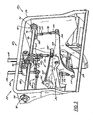
Fig. 2 is a front elevational view of the power trowel shown inFig. 1 with a center portion of a cage of the trowel being shown as cut away to expose more a steering assembly of the trowel; -
Fig. 3 is front perspective view of the steering assembly shown inFig. 2 ; -
Fig. 4 is a side perspective view of the steering assembly shown inFig. 3 ; -
Fig. 5 is a sectional view of the steering system along line 5-5 shown inFig. 4 ; -
Fig. 6 is a schematic representation of the steering assembly shown inFig. 3 ; -
Fig. 7 is a side elevational view of the steering assembly shown inFig. 3 ; -
Fig. 8 schematically illustrates another embodiment of a steering assembly for a riding power trowel according to the present invention; -
Fig. 9 schematically illustrates yet another embodiment of a steering assembly for a riding power trowel according to the present invention; -
Fig. 10 schematically illustrates a further embodiment of a steering assembly for a riding power trowel according to the present invention; -
Fig. 11 is a graphical representation comparing the operation of the steering assemblies shown inFigures 2-7 and9 to other known steering assemblies; and -
Fig. 12 is a graphical representation comparing holding forces required of the steering assembly shown inFig. 2-7 to those required for a prior known assisted steering system. -
Fig. 1 shows a self-propelled ridingconcrete finishing trowel 20 equipped with asteering system 22 according to present invention.Steering system 22steers machine 20 by tilting the driven shafts of therotor assemblies machine 20 without requiring the imposition of fatiguing actuating forces by the machine's operator.Steering system 22 includes one, and preferably two, control arms or handles 28, 30 that extend beyond a shroud orcage 32 oftrowel 20.Handles trowel 20 to be manipulated by an operator positioned in a seat 34. -
Handles rotor assemblies handles rotor assembly frame 36 oftrowel 20, respectively. In the typical case in which the machine is laterally steered by pivoting a gearbox of at least one rotor assembly about two axes, at least one ofhandles - Referring to
Figs. 1-7 , and initially toFig. 1 in particular,concrete finishing trowel 20 in accordance with a preferred embodiment of the invention includes as its major components rigidmetallic frame 36, an upper deck 38 mounted onframe 36, an operator's platform or pedestal 40 provided on the deck, and right and leftrotor assemblies machine 20 on the surface to be finished. Therotor assemblies Cage 32 is positioned at the outer perimeter ofmachine 20 and extends downwardly fromframe 36 to the vicinity of the surface to be finished. The pedestal 40 is positioned generally longitudinally centrally on deck 38 at a rear portion thereof and supports operator's seat 34. Afuel tank 44 is disposed adjacent the left side of pedestal 40, and awater retardant tank 46 is disposed on the right side of pedestal 40. Alift cage assembly 48, best seen inFig 1 , is attached to the upper surface of the deck 38 beneath pedestal 40 and seat 34. - Referring to
Figs. 1 ,3 , and6 , eachrotor assembly gearbox 58, a drivenshaft 60 extending downwardly from the gearbox, and a plurality of circumferentially-spacedblades 62 supported on the drivenshaft 60 via radial support arms 64 and extending radially outwardly from the bottom end of the drivenshaft 60 so as to rest on the concrete surface. Eachgearbox 58 is mounted on the undersurface of the deck 38 so as to be tiltable relative to deck 38 andframe 36 for reasons detailed below. - The pitch of the
blades 62 of each of the right and leftrotor assemblies pitch adjustment assembly 70. Each bladepitch adjustment assembly 70 includes a generally vertical post 72 and a crank 74 which is mounted on top of the post 72, and which can be rotated by an operator positioned in seat 34 to vary the pitch of thetrowel blades 62. In the typical arrangement, a thrust collar (not shown) cooperates with ayoke 78 that is movable to force thethrust collar 76 into a position pivotingtrowel blades 62 about an axis extending perpendicular to the axis of the drivenshaft 60. A tension cable 80 extends from the crank 74, through the post 72, and to theyoke 78 to interconnect theyoke 78 with the crank 74. Rotation of the crank 74 adjusts the yoke's angle to move thethrust collar 76 up or down thereby providing a desired degree of trowel blade pitch adjustment. The pitch ofblades 62 is often varied as the material being finished sets and becomes more resistant to being worked by the blades. A power concrete finishing trowel having this type of blade pitch adjustment assembly is disclosed, e.g., inU.S. Pat. No. 2,887,934 to Whiteman . - Both
rotor assemblies trowel 20, are driven by a power source such as internal combustion engine 42 mounted under operator's seat 34. The size of engine 42 will vary with the size of themachine 20 and the number of rotor assemblies powered by the engine. The illustrated two-rotor 1.219 meter (48 inches) machine typically will employ an engine of about 35 hp.Rotor assemblies Figs 2-7 ). - As is typical of riding concrete finishing trowels of this type, the
machine 20 is steered by tilting a portion or all of each of therotor assemblies blades 62 generates horizontal forces that propelmachine 20. The steering direction is generally perpendicular to the direction of rotor assembly tilt. Hence, side-to-side and fore-and-aft rotor assembly tiltingcause machine 20 to move forward/reverse and left/right, respectively. The most expeditious way to effect the tilting required for steering control is by tilting theentire rotor assemblies gearboxes 58. The discussion that follows therefore will describe a preferred embodiment in which theentire gearboxes 58 tilt, it being understood that the invention is equally applicable to systems in which other components of therotor assemblies - More specifically, the
machine 20 is steered to move forward by tilting thegearboxes 58 laterally to increase the pressure on the inner blades of eachrotor assembly gearboxes 58 laterally to increase the pressure on the outer blades of eachrotor assembly right rotor assembly 24 in the illustrated embodiment), with forward tilting ofright rotor assembly 24 increasing the pressure on the front blades of therotor assembly 24 to steer themachine 20 to the right. Similarly, rearward tilting ofrotor assembly 24 increases the pressure on the back blades of therotor assembly 24 thereby steeringmachine 20 to the left. -
Steering system 22 tilts thegearboxes 58 of the right and leftrotor assemblies handles Figs. 2-4 ,steering system 22 generally includes a leftrotor steering linkage 82 and a rightrotor steering linkage 84. As best shown inFig. 2 , (except for the fact that the right steering linkage contains additional components enabling left/right steering) left and rightrotor steering linkages rod first end 90 and asecond end 92 that are rotationally coupled to frame 36 ofmachine 20.Bearing 94 supports each of the generally opposite ends of steeringrods arm 96 extends generally rearwardly from each steeringrod arm 96 about an axis of therespective steering rod - A
link 98 is connected to eachsteering arm 96 at a location behind the steeringrod Link 98 includes afirst end 100 having a pivot 102 for pivotably connectingfirst end 100 oflink 98 tosteering arm 96. Anotherpivot 104 pivotably connects asecond end 106 oflink 98 to arocker arm 108. Preferably, link 98 includes anadjuster 110 for adjusting a length oflink 98, thereby reducing play in steeringsystem 22 and facilitating presets. As best shown inFigs. 3 and6 , apivot 112 securesrocker arm 108 to frame 36 such thatrocker arm 108 can be rotated aboutpivot 112. Apivot pin 114 connects anotherlink 116 to an end ofrocker arm 108 generallyopposite link 98.Link 116 includes ajournal 118 connected to apivot lever assembly 120 associated with eachgearbox 58. As shown inFig. 6 , translation ofhandle 28 in fore and aft directions, indicated byarrow 122, imparts a rotational force, indicated byarrow 124, upon steeringrod 88.Rotation 124 pivotsarm 96 about axis 126 of steeringrod 88. Such motion translateslink 98 generally vertically, as indicated by arrow 128. The motion oflink 98 is translated throughrocker arm 108 such that, whenlink 98 is raised or lowered,rocker arm 108 rotates aboutpivot 112 to lower or raisepivot link 116. - The upper end of
link 116 is pivotally connected to an outer end of a laterally extending rod 117. The opposite ends of the rod 117 are journalled inpillow block bearings 119 attached to the upper surface of thegearbox 58. A central portion of the rod 117 is welded or otherwise affixed to alongitudinally extending rod 121 having opposite ends journalled inpillow block bearings 123. Thepillow block bearings 123 are bolted on the underside of the frame. - With this arrangement, translation of
link 116 along the direction indicated byarrow 130tilts gearbox 58 about alongitudinal axis 132 ofpivot lever assembly 120. Accordingly, forward translation ofhandle 28tilts gearbox 58 in the direction indicated by arrow 134 such thatblades 62 contact the material being finished so as to move the machine in a forward direction. In a similar manner, rearward translation ofhandle 28tilts gearbox 58 in the direction indicated byarrow 136 such thatblades 62 to contact the material being finished so as to move the machine in a rearward direction. Theshaft 121 rotates inpillow block bearings 123 to accommodate this motion. - Referring to
Figs. 3 ,5 , and6 ,steering system 22 additionally includes a crab orlateral steering linkage 200.Lateral steering linkage 200 extends to only one ofrotor assemblies Fig. 6 ), one ofrotor assemblies axis 204 that is generally aligned with a longitudinal axis ofmachine 20. Such a construction results inblades 62 imparting a lateral, crab, or side-to-side force tomachine 20 upon lateral or side-to-side motion ofhandles Fig. 3 ,lateral steering linkage 200 includes a gear box link 206 and a handle link 208. Gear box link 206 extends between one of thehandles respective rotor assembly machine 20, a handle link 208 secureshandles machine 20 can be accomplished with lateral translation of either handle 28 or handle 30. - Although handle link 208 connects the operation of
handles handles machine 20 and each handle 28, 30 to control the forward and rearward direction of travel tilting of therotor assembly - Referring to
Figs. 2-4 ,steering system 22 includes anassistance system 140 associated with eachhandle assistance system 140 is constructed to overcome at least a portion of the load associated with tiltinggearboxes 58. Eachassistance system 140 includes a biasing device that is operationally connected to arespective steering rod Figs 1-6 , the biasing device comprises atorsion bar 142. As best shown inFig. 4 , an outer end 144 oftorsion bar 142 passes through anopening 146 formed inframe 36 and loosely secures a position oftorsion bar 142 relative to frame 36. An upperend anchor bar 148 is rigidly secured to outer end 144 oftorsion bar 142proximate opening 146. An upper end 150 ofanchor bar 148 includes aclamp 152 that secures the orientation ofanchor bar 148 relative totorsion bar 142.Anchor bar 148 includes anadjuster 154 positioned proximate an opposite, lower end 156 of theanchor bar 148.Adjuster 154 includes a threaded rod 158 that engagesanchor bar 148 andframe 36 such that the position ofanchor bar 148 relative to frame 36 can be adjusted. The position ofadjuster 154 andanchor bar 148 determines the preloading oftorsion bar 142. Another, inboard end 160 oftorsion bar 142 is loosely supported by asaddle 162 that is attached to frame 36. This construction allowstorsion bar 142 to move independent offrame 36 and provides for variable loading oftorsion bar 142 such that the variable load is selectively communicated tohandles - A
rigid lever 164 is rigidly attached totorsion bar 142 generally between ends 144, 160. The first end 166 ofrigid lever 164 is secured totorsion bar 142 such thatrigid lever 164 does not rotate independent oftorsion bar 142. As best seen inFig. 3 ,alink assembly shaft Upper link 168 comprises a clevis fixed to the steeringrod Lower link 170 comprises a turnbuckle pivotally attached to the bottom of theupper link 168 at its upper end and to thelever 164 at its lower end. Rotation of steeringrod upper link 168 to swing, resulting in over-center motion of thelower link 170 about its upper end with the assistance of the preload imposed in thetorsion bar 142. Such a construction selectively communicates the preload oftorsion bar 142 to therespective handle steering system 22 to assist in overcoming the forces experienced athandles rotor assemblies torsion bar 142 through pivoting of theanchor bar 148 imparts a preload on thelever 164 that assists the operator in overcoming a portion of the force otherwise associated with tiltingrotor assemblies machine 20. -
Figs. 5 and7 show the various positions ofhandles handle 28 is varied. As shown inFig. 7 , when handles 28, 30 are oriented in the neutral position, as indicated byarrow 180, fixedlink 168 andadjustable link 170 are oriented in an under center position with respect to an axis of steeringrod torsion bar 142 when handles 28, 30 are oriented inneutral position 180. Translation ofhandles arrow 182, translates fixedlink 168 rearward ofneutral position 180 such that the bias or pre-load oftorsion bar 142, indicated by arrow 184, is communicated fromtorsion bar 142 to steeringrod rigid lever 164 and fixed andadjustable links handle 28 toward a rearward position, indicated byarrow 186, translates fixedlink 168 forward ofneutral position 180. Such an orientation also translates the pre-load 184 oftorsion bar 142 to steeringrod torsion bar 142 is communicated to steeringrod handles machine 20 androtor assemblies assistance system 140 assists in overcoming the load associated with tiltingrotor assemblies machine 20. The same preload resists return of thehandles handles -
Adjuster 154 andanchor bar 148 are also constructed to provide variable loading oftorsion bar 142. Such a construction allows steeringsystem 22 to be quickly and efficiently adapted to any of a number of machines and a number of machine configurations.Adjuster 154 also allowsassistance system 140 to be uniquely configured to an individual operator's preferences. That is,assistance system 140 can be configured to allow as much of the resistance to tilting of the rotor to be communicated tohandles steering assistance system 140 support most, if not all, of the load commonly communicated tohandles steering rods assistance system 140 be configured to support anywhere from 50 to 800 or more lbs. Understandably these values are only dependent on the amount of resistance an operator desires to overcome and the total amount of resistance generated by the tilting operation. It is envisioned thatassistance system 140 andtorsion bar 142 could be configured to provide any of a number of steering assistance values. -
Figs. 8-10 show simplified representations of alternate embodiments of steering assistance systems for use with ride-ontrowels 20 according to the present invention. As shown inFig. 8 , asteering assistance system 220 according to another embodiment of the invention includes asteering rod 222 that is rotationally connected to asteering handle 224. Anarm 226 extends from steeringrod 222 such that rotation ofrod 222 rotatesarm 226 about anaxis 227 ofrod 222. Alink 228 is coupled between arocker arm 230 andarm 226.Rocker arm 230 is constructed to pivot about apivot pin 232 attached to a frame of the machine.Rocker arm 230 is connected to apivot lever assembly 234 such that movement ofrocker arm 230 manipulates agearbox 236 generally similar to the operation ofrocker arm 108. A biasing lever or torsion bar 238 includes afirst end 240 that is attached to a frame of the machine and anotherend 242 having anarm 244 extending therefrom. Alink 246 connectsarm 244 andarm 226 of steeringrod 222.Link 246 is adjustable to define the relative degree of rotation or loading, indicated byarrow 248, of torsion bar 238.Link 246 is generally aligned under center ofaxis 227 of steeringrod 222 such that manipulation ofhandle 224 in either a forward or rearward direction allows communication of the load of torsion bar 238 to steeringrod 222. Additionally, it is appreciated that either oftorsion bars 142, 238 be provided in the form of a torsion spring or other member configured to retain rotational energy. -
Fig. 9 shows another alternate embodiment of a steering assistance system 260 according to the present invention. The connection between the steeringrod 222 and pivot lever assembly is substantially similar to that already described with respect tosteering assistance systems first link 262 secured to steeringrod 222 and anotherlink 264 pivotably secured to frame 36. Eachlink first arm 266, 268 interconnected by arod 270. Asecond arm link compression spring 276. Arm 266 includes a number ofholes 278 constructed to engage link 270 such that a preloading ofcompression spring 276 is manipulated by manipulation of the connection oflink 270 and arm 266.Arms rod 222 whenhandle 224 is located in a neutral position. Rotation ofhandle 224 in either a forward or rearward direction upsets the over center orientation ofcompression spring 276 andsteering arm 222 thereby allowing the communication of the preload ofcompression spring 276 to steeringrod 222. Accordingly, steering assistance system 260 also assists an operator in overcoming the forces associated with tilting either ofrotor assemblies -
Fig. 10 shows a further embodiment of asteering assistance system 280 according to the present invention. Handle 224 is coupled to steeringrod 222 and connected to pivotlever assembly 234 androtor assemblies systems 220, 260.Arm 226 extends from steeringrod 222 and is connected torocker arm 230 vialink 228.Assistance system 280 includes alink 282 constructed to rotate about apivot 284 having a position that is fixed relative torocker arm 230. A biasing link ortension spring 286 extends betweenlink 282 and afixed position 288. An adjustable connection link 290 extends betweenarm 226 and link 282. Link 290 engages link 282 generally betweentension spring 286 andpivot 284. Link 290 is generally oriented over center of steeringrod 222 such that manipulation ofhandle 224 in either a forward or rearward direction communicates the load oftension spring 286 to steeringrod 222 in the direction of rotation of the steering rod. Adjustable link 290 allowsassistance system 280 to also be configured to provide any of a variety of preload conditions totension spring 286 such that the user can quickly and efficiently configure the assistance system to provide the desired level of steering assistance. - Each
steering assistance system Fig. 11 . it has been determined that very few power trowel steer assist systems provide a relatively uniform and substantial assistance to overcoming the anti-tilt forces of the rotor assemblies over a majority of the range of motion of the handles of such devices. -
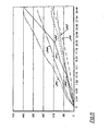
Fig. 11 depicts handle force (Newton) over handle travel (centimeters) for different sytems (300: Handle Force CRT 48-35L Assist; 302: Handle Force Allen 40-27; 304: Handle Force CRT 48 - 33V; 306: Handle Force HHN48 32TVD NO/A; 308: Handle Force CRT 48-35L: 310: Handle Force HHN 48-34TVD) -
Fig. 11 shows graphically that a riding trowel equipped with a steering assistance system according to the first preferred embodiment of the present invention, indicated bytrend 300, requires the least amount of operator effort through approximately 25, 4 cm (ten inches) of handle travel. A riding trowel equipped with a steering assistance system according to the second preferred embodiment of the present invention, indicated bytrends 304, required similarly low operator efforts through the full range of handle stroke. These efforts are commensurate with those required for operation of a manually steered trowel manufactured by Allen Engineering, as depicted bycurve 302. The Allen Engineering system achieves these low actuation forces by utilizing a specially designed linkage with high mechanical advantage. However, because the Allen Engineering system lacks a steering assist mechanism that stores potential energy and releases it to assist in steering, the forces required - to hold the steering handles in a particular position after moving to that position are commensurate with those required to move the handle to that position. However, because the inventive steering assist system uses released potential energy to assist in steering, the forces required to maintain the handle in a particular position after achieving that position are relatively low, as will be discussed below in conjunction with
Fig. 12 . - The required operator effort of both inventive systems referenced above is much less than is required to operate a prior art trowel that is manufactured by Wacker Corporation and that has a steering system that is quite similar to those described herein but for the inventive steering assist mechanism. Compare
curves curve 306. - The operator effort required for both respective inventive systems referenced above is also comparable or less than a prior art assisted steering system marketed by Whiteman and described in
U.S. Patent No. 5,899,631 through about the first 20.32 cm (8 inches) of handle stroke, as represented by a comparison ofrespective curves break point 318 in thecurve 316 of retired retention forces at a particular handle position as depicted inFig. 12 . As can be seen bycurve 314 representing retention forces for the above-referenced trowel constructed in accordance with the first preferred embodiment of the invention, the required retention forces for the inventive trowel are less than those required for the Whiteman steering assisted trowel over about the last 7.62 cm (3 inches) or 25% of handle stroke. The maximum retention force required for the inventive trowel described above are about 44.5 Newton (10 lbs). This is dramatically less than the approximately 155 Newton (35 lbs) maximum retention force required of the Whiteman assisted steering system and substantially less than is required in all known unassisted systems in which the retention forces are commensurate with the actuating forces. This differential is very significant because, on large surfaces, an operator may have to hold the handles in a particular position for a relatively long period of time to propel the machine forward at a desired, constant speed, resulting in operator fatigue. - Hence, the inventive system reduces operator effort to impose and maintain steering forces through the operating stroke of the steering levers.
- It is appreciated that many changes and modifications could be made to the invention without departing from the spirit thereof. Some of these changes, such as its applicability to riding concrete finishing trowels having other than two rotors and even to other self-propelled powered finishing trowels, are discussed above. Other changes will become apparent from the appended claims. It is intended that all such changes and/or modifications be incorporated in the appending claims.
Claims (9)
- A riding power trowel (20), the trowel (20) having at least one rotor assembly (24, 26) including a rotatable shaft (60) and a plurality of blades (62), the rotor assembly (24, 26) being tiltable to steer the power trowel (20), the power trowel (20) having a steering system (22) comprising:at least one handle (28, 30) that can be manipulated by an operator, the handle (28, 30) having an operating stroke ranging from a neutral position (180) in which the shaft (60) of the rotor assembly (24, 26) extends at least substantially vertically to a maximum stroke position (182, 186) in which the shaft (60) of the rotor assembly (24, 26) is tilted a maximum possible amount;a steering linkage (82, 84) that connects the at least one handle (28, 30) to a rotor assembly (24, 26) and that tilts the rotor assembly (24, 26) upon handle (28, 30) manipulation;a steering assist mechanism (140, 220) is provided that imposes a preload on the steering linkage (82, 84) to reduce handle actuation forces required to move the handle (28, 20) to a particular position, and characterized in that the steering assist mechanism (140, 220) reduces handle retention forces, required to maintain the handle (28, 30) in a particular position after moving the handle to that position, to less than about 89 Newton (20 lbs) throughout the operating stroke of the handle.
- The riding power trowel (20) as recited in claim 1, wherein the steering assist mechanism (140, 220) comprises a torsion bar (238) which, upon handle movement away from the neutral position (180), imposes a load on the handle (28, 30) that assists handle motion away from the neutral position (180).
- The riding power trowel (20) as recited in claim 2, further comprising a biasing link (276) engaged with the steering linkage (84, 86) and extending from the torsion bar (238) between generally opposite ends of the torsion bar (238); and
a load link (98, 170) that is connected to the torsion bar (238) and that imparts a preload on the torsion bar (238). - The riding power trowel (20) of claim 3, further comprising an adjuster (110) that engages the load link (98, 170) and that can be operated to adjust an amount of the preload.
- The riding power trowel (20) of claim 3, wherein the steering linkage (82, 84) further comprises a link assembly (168, 170) connected to the at least one handle (28, 30) and the biasing link (276), the link assembly (168, 170) aligning a load of the biasing link (276) with an axis of rotation of the steering link (82, 84) to isolate the at least one handle (28, 30) from the preload when the at least one handle (28, 30) is in the neutral position (180) thereof.
- The riding power trowel (20) of claim 1, further comprising a frame (36) that supports
a first (24) and a second rotor assembly (26) extend downwardly from the frame (36), each rotor assembly (24, 26) having a shaft (60) that supports a plurality of blades (62), and wherein each rotor assembly (24, 26) is tiltable relative to the frame (36) to steer the trowel (20);
an engine (42) that drives the shafts (60) of the rotor assemblies (24, 26) to translate the blades (62) across a concrete material,
first and second handles (28, 30), each of which is coupled to an associated rotor assembly (24, 26), each of the handles (28, 30) having an operating stroke ranging from a neutral position in which the shaft (60) of the associated rotor extends at least generally vertically to a maximum stroke position in the which shaft (60) of the associated rotor assembly (24, 26) is tilted a maximum possible amount;
first and second steering linkages (82, 84), each of which connects an associated handle (28, 30) to an associated rotor assembly (24, 26) to tilt the associated rotor assembly (24, 26) relative to the frame (36),
first and second steering assist mechanisms (140), each of which is coupled to an associated steering linkage (82, 84) and which reduces handle retention forces required to hold the associated handle (28, 30) to a particular position, after moving the handle (28, 30) to that position, to less than about 89 Newton (20 Ibs) throughout the stroke of the operating handle, and
wherein each rotor assembly (24, 26) includes a steering assist mechanism (140, 220) that comprises a torsion bar (238) and a lever (164) that is rigidly connected to the torsion bar (238) and extends between the torsion bar (238) and the steering linkage (82, 84). - The riding power trowel (20) of claim 6, wherein only one of the first and second rotor assemblies (24, 26) is tiltable about more than one axis.
- The riding power trowel (20) of claim 6 further comprising a seat (34) positioned generally between the rotor assemblies (24, 26) for supporting an operator.
- A method of manually steering a riding power trowel (20) comprising:providing a riding power trowel (20) having at least one rotor assembly (24, 26) including a rotatable shaft (60) and a plurality of blades (62), the rotor assembly (24, 26) being tiltable to steer the power trowel (20), a handle (28, 30) that can be manipulated by an operator, and a steering linkage (82, 84) that connects the handle (28, 30) to the rotor assembly (24, 26) and that tilts the rotor assembly (24, 26) upon handle manipulation,steering the trowel by moving the handle (28, 30) through an operating stroke ranging from a neutral position (180) in which the shaft of the rotor assembly (24, 26) extends vertically to a maximum stroke position (182, 186) in which the shaft (60) of the rotor assembly (24, 26) is tilted a maximum possible amount; characterized in thatduring the steering step, assisting steering is performed by imposing a preload on the steering linkage (82, 84), wherein the preload reduces handle retention forces, required to maintain the handle (28, 30) in a particular position after pivoting the handle to that position, to less than about 89 Newton (20 lbs) throughout the operating stroke of the operating handle (28, 30).
Applications Claiming Priority (1)
| Application Number | Priority Date | Filing Date | Title |
|---|---|---|---|
| US11/782,844 US7775740B2 (en) | 2007-07-25 | 2007-07-25 | Concrete trowel steering system |
Publications (3)
| Publication Number | Publication Date |
|---|---|
| EP2022907A2 EP2022907A2 (en) | 2009-02-11 |
| EP2022907A3 EP2022907A3 (en) | 2009-07-22 |
| EP2022907B1 true EP2022907B1 (en) | 2013-07-17 |
Family
ID=39832728
Family Applications (1)
| Application Number | Title | Priority Date | Filing Date |
|---|---|---|---|
| EP08013465.3A Active EP2022907B1 (en) | 2007-07-25 | 2008-07-25 | Riding power trowel and method of manually operating the same |
Country Status (7)
| Country | Link |
|---|---|
| US (1) | US7775740B2 (en) |
| EP (1) | EP2022907B1 (en) |
| JP (1) | JP5495521B2 (en) |
| CN (1) | CN101357486B (en) |
| AU (1) | AU2008203303B2 (en) |
| BR (1) | BRPI0804450A2 (en) |
| CA (1) | CA2638272C (en) |
Families Citing this family (15)
| Publication number | Priority date | Publication date | Assignee | Title |
|---|---|---|---|---|
| US8132983B2 (en) * | 2008-01-18 | 2012-03-13 | Wacker Neuson Production Americas Llc | Riding concrete trowel with stabilizers |
| USD618256S1 (en) * | 2009-01-29 | 2010-06-22 | Larry Jake Chapple | Frame member for ride-on power trowel |
| USD602961S1 (en) * | 2009-01-29 | 2009-10-27 | Multiquip, Inc. | Ride-on power trowel |
| USD615561S1 (en) * | 2009-01-29 | 2010-05-11 | Larry Jake Chapple | Mid section for ride-on machine |
| US20110033235A1 (en) * | 2009-02-03 | 2011-02-10 | Bartell Morrison | Concrete finishing trowel with speed control |
| US8132984B2 (en) | 2009-04-01 | 2012-03-13 | Wacker Neuson Production Americas Llc | Multiple preset concrete trowel steering system |
| US8414219B2 (en) | 2010-12-22 | 2013-04-09 | Wacker Neuson Production Americas Llc | Concrete trowel transport system |
| US8388264B2 (en) | 2010-12-22 | 2013-03-05 | Wacker Neuson Production Americas Llc | Method and apparatus for controlling engine speed of a self-propelled power trowel during high load conditions |
| US9068300B2 (en) | 2013-09-30 | 2015-06-30 | Allen Engineering Corporation | Riding trowel with CVT clutch module |
| US9068301B2 (en) * | 2013-10-01 | 2015-06-30 | Allen Engineering Corporation | Single to dual stick trowel and steering conversion |
| US10961724B2 (en) * | 2016-12-20 | 2021-03-30 | 2544-9455 Quebec Inc. | Powered concrete finishing apparatus having annular working surface |
| CN111778810B (en) * | 2020-06-23 | 2022-04-01 | 苏州东振路桥工程有限公司 | Mixing method of hot-mixed asphalt mixture |
| SE547045C2 (en) * | 2020-12-18 | 2025-04-08 | Husqvarna Ab | Concrete surface processing machines, systems, and methods for processing concrete surfaces |
| US12442202B2 (en) | 2021-02-24 | 2025-10-14 | Milwaukee Electric Tool Corporation | Concrete trowel |
| WO2022192499A1 (en) * | 2021-03-11 | 2022-09-15 | Milwaukee Electric Tool Corporation | Concrete trowel |
Family Cites Families (9)
| Publication number | Priority date | Publication date | Assignee | Title |
|---|---|---|---|---|
| US2887934A (en) | 1956-04-06 | 1959-05-26 | Marvin E Whiteman | Cement finishing machine |
| US4046484A (en) * | 1976-11-15 | 1977-09-06 | Orville H. Holz, Jr. | Spaced-rotor ride-type surface working machine with single-stick control of all movements |
| US5108220A (en) * | 1990-07-13 | 1992-04-28 | Allen Engineering Corporation | Light weight, fast steering riding trowel |
| US5480258A (en) * | 1993-12-30 | 1996-01-02 | Allen Engineering, Inc. | Variable width, twin engine riding trowel |
| US5899631A (en) * | 1998-03-19 | 1999-05-04 | Whiteman Industries, Inc. | Assisted steering linkage for a riding power trowel |
| US6250844B1 (en) * | 1999-07-13 | 2001-06-26 | Wacker Corporation | Concrete finishing trowel with improved rotor assembly drive system |
| US6368016B1 (en) * | 1999-07-13 | 2002-04-09 | Wacker Corporation | Concrete finishing trowel having an electronically actuated steering assembly |
| US6974277B2 (en) * | 2003-11-07 | 2005-12-13 | Wacker Corporation | Dynamically balanced walk behind trowel |
| US7065837B2 (en) * | 2003-11-07 | 2006-06-27 | Wacker Corporation | Guide handle for a manually steered machine |
-
2007
- 2007-07-25 US US11/782,844 patent/US7775740B2/en active Active
-
2008
- 2008-07-24 BR BRPI0804450-3A patent/BRPI0804450A2/en not_active IP Right Cessation
- 2008-07-24 CA CA2638272A patent/CA2638272C/en active Active
- 2008-07-24 AU AU2008203303A patent/AU2008203303B2/en not_active Ceased
- 2008-07-25 CN CN2008101686287A patent/CN101357486B/en not_active Expired - Fee Related
- 2008-07-25 JP JP2008191645A patent/JP5495521B2/en not_active Expired - Fee Related
- 2008-07-25 EP EP08013465.3A patent/EP2022907B1/en active Active
Also Published As
| Publication number | Publication date |
|---|---|
| EP2022907A3 (en) | 2009-07-22 |
| US7775740B2 (en) | 2010-08-17 |
| CN101357486A (en) | 2009-02-04 |
| BRPI0804450A2 (en) | 2010-03-30 |
| JP5495521B2 (en) | 2014-05-21 |
| US20090028642A1 (en) | 2009-01-29 |
| CA2638272C (en) | 2015-11-24 |
| EP2022907A2 (en) | 2009-02-11 |
| AU2008203303B2 (en) | 2014-10-09 |
| CA2638272A1 (en) | 2009-01-25 |
| CN101357486B (en) | 2013-05-08 |
| JP2009062806A (en) | 2009-03-26 |
| AU2008203303A1 (en) | 2009-02-12 |
Similar Documents
| Publication | Publication Date | Title |
|---|---|---|
| US7775740B2 (en) | Concrete trowel steering system | |
| EP1069259B1 (en) | Concrete finishing trowel having an electronically actuated steering assembly | |
| US6089786A (en) | Dual rotor riding trowel with proportional electro-hydraulic steering | |
| EP2002703B1 (en) | Neutral adjustment mechanism | |
| EP2236697B1 (en) | A rotary trowel having a steering system with multiple preset steering modes | |
| US6053660A (en) | Hydraulically controlled twin rotor riding trowel | |
| US6250844B1 (en) | Concrete finishing trowel with improved rotor assembly drive system | |
| US5816740A (en) | Hydraulically controlled steering for power trowel | |
| EP2025831A2 (en) | Concrete trowel transport system | |
| US7467677B2 (en) | Control mechanism for zero turning radius mower | |
| JP2001073313A5 (en) | ||
| US8132983B2 (en) | Riding concrete trowel with stabilizers | |
| US20110033235A1 (en) | Concrete finishing trowel with speed control | |
| HK1128742A (en) | Concrete trowel steering system | |
| HK1148797A (en) | A rotary trowel having a steering system with multiple preset steering modes | |
| HK1132774A (en) | Riding concrete trowel with stabilizer |
Legal Events
| Date | Code | Title | Description |
|---|---|---|---|
| PUAI | Public reference made under article 153(3) epc to a published international application that has entered the european phase |
Free format text: ORIGINAL CODE: 0009012 |
|
| AK | Designated contracting states |
Kind code of ref document: A2 Designated state(s): AT BE BG CH CY CZ DE DK EE ES FI FR GB GR HR HU IE IS IT LI LT LU LV MC MT NL NO PL PT RO SE SI SK TR |
|
| AX | Request for extension of the european patent |
Extension state: AL BA MK RS |
|
| PUAL | Search report despatched |
Free format text: ORIGINAL CODE: 0009013 |
|
| AK | Designated contracting states |
Kind code of ref document: A3 Designated state(s): AT BE BG CH CY CZ DE DK EE ES FI FR GB GR HR HU IE IS IT LI LT LU LV MC MT NL NO PL PT RO SE SI SK TR |
|
| AX | Request for extension of the european patent |
Extension state: AL BA MK RS |
|
| REG | Reference to a national code |
Ref country code: HK Ref legal event code: DE Ref document number: 1128742 Country of ref document: HK |
|
| 17P | Request for examination filed |
Effective date: 20100114 |
|
| AKX | Designation fees paid |
Designated state(s): AT BE BG CH CY CZ DE DK EE ES FI FR GB GR HR HU IE IS IT LI LT LU LV MC MT NL NO PL PT RO SE SI SK TR |
|
| 17Q | First examination report despatched |
Effective date: 20110224 |
|
| RAP1 | Party data changed (applicant data changed or rights of an application transferred) |
Owner name: WACKER NEUSON CORPORATION |
|
| RAP1 | Party data changed (applicant data changed or rights of an application transferred) |
Owner name: WACKER NEUSON PRODUCTION AMERICAS LLC |
|
| GRAP | Despatch of communication of intention to grant a patent |
Free format text: ORIGINAL CODE: EPIDOSNIGR1 |
|
| RIC1 | Information provided on ipc code assigned before grant |
Ipc: E04F 21/24 20060101AFI20130123BHEP |
|
| GRAS | Grant fee paid |
Free format text: ORIGINAL CODE: EPIDOSNIGR3 |
|
| GRAA | (expected) grant |
Free format text: ORIGINAL CODE: 0009210 |
|
| AK | Designated contracting states |
Kind code of ref document: B1 Designated state(s): AT BE BG CH CY CZ DE DK EE ES FI FR GB GR HR HU IE IS IT LI LT LU LV MC MT NL NO PL PT RO SE SI SK TR |
|
| REG | Reference to a national code |
Ref country code: GB Ref legal event code: FG4D |
|
| REG | Reference to a national code |
Ref country code: CH Ref legal event code: EP |
|
| REG | Reference to a national code |
Ref country code: IE Ref legal event code: FG4D |
|
| REG | Reference to a national code |
Ref country code: AT Ref legal event code: REF Ref document number: 622342 Country of ref document: AT Kind code of ref document: T Effective date: 20130815 |
|
| REG | Reference to a national code |
Ref country code: DE Ref legal event code: R096 Ref document number: 602008026001 Country of ref document: DE Effective date: 20130912 |
|
| REG | Reference to a national code |
Ref country code: SE Ref legal event code: TRGR |
|
| REG | Reference to a national code |
Ref country code: AT Ref legal event code: MK05 Ref document number: 622342 Country of ref document: AT Kind code of ref document: T Effective date: 20130717 |
|
| REG | Reference to a national code |
Ref country code: NL Ref legal event code: VDEP Effective date: 20130717 |
|
| REG | Reference to a national code |
Ref country code: LT Ref legal event code: MG4D |
|
| PG25 | Lapsed in a contracting state [announced via postgrant information from national office to epo] |
Ref country code: NO Free format text: LAPSE BECAUSE OF FAILURE TO SUBMIT A TRANSLATION OF THE DESCRIPTION OR TO PAY THE FEE WITHIN THE PRESCRIBED TIME-LIMIT Effective date: 20131017 Ref country code: BE Free format text: LAPSE BECAUSE OF FAILURE TO SUBMIT A TRANSLATION OF THE DESCRIPTION OR TO PAY THE FEE WITHIN THE PRESCRIBED TIME-LIMIT Effective date: 20130717 Ref country code: AT Free format text: LAPSE BECAUSE OF FAILURE TO SUBMIT A TRANSLATION OF THE DESCRIPTION OR TO PAY THE FEE WITHIN THE PRESCRIBED TIME-LIMIT Effective date: 20130717 Ref country code: CY Free format text: LAPSE BECAUSE OF FAILURE TO SUBMIT A TRANSLATION OF THE DESCRIPTION OR TO PAY THE FEE WITHIN THE PRESCRIBED TIME-LIMIT Effective date: 20130724 Ref country code: HR Free format text: LAPSE BECAUSE OF FAILURE TO SUBMIT A TRANSLATION OF THE DESCRIPTION OR TO PAY THE FEE WITHIN THE PRESCRIBED TIME-LIMIT Effective date: 20130717 Ref country code: LT Free format text: LAPSE BECAUSE OF FAILURE TO SUBMIT A TRANSLATION OF THE DESCRIPTION OR TO PAY THE FEE WITHIN THE PRESCRIBED TIME-LIMIT Effective date: 20130717 Ref country code: IS Free format text: LAPSE BECAUSE OF FAILURE TO SUBMIT A TRANSLATION OF THE DESCRIPTION OR TO PAY THE FEE WITHIN THE PRESCRIBED TIME-LIMIT Effective date: 20131117 Ref country code: PT Free format text: LAPSE BECAUSE OF FAILURE TO SUBMIT A TRANSLATION OF THE DESCRIPTION OR TO PAY THE FEE WITHIN THE PRESCRIBED TIME-LIMIT Effective date: 20131118 |
|
| PG25 | Lapsed in a contracting state [announced via postgrant information from national office to epo] |
Ref country code: ES Free format text: LAPSE BECAUSE OF FAILURE TO SUBMIT A TRANSLATION OF THE DESCRIPTION OR TO PAY THE FEE WITHIN THE PRESCRIBED TIME-LIMIT Effective date: 20131028 Ref country code: NL Free format text: LAPSE BECAUSE OF FAILURE TO SUBMIT A TRANSLATION OF THE DESCRIPTION OR TO PAY THE FEE WITHIN THE PRESCRIBED TIME-LIMIT Effective date: 20130717 Ref country code: GR Free format text: LAPSE BECAUSE OF FAILURE TO SUBMIT A TRANSLATION OF THE DESCRIPTION OR TO PAY THE FEE WITHIN THE PRESCRIBED TIME-LIMIT Effective date: 20131018 Ref country code: FI Free format text: LAPSE BECAUSE OF FAILURE TO SUBMIT A TRANSLATION OF THE DESCRIPTION OR TO PAY THE FEE WITHIN THE PRESCRIBED TIME-LIMIT Effective date: 20130717 Ref country code: SI Free format text: LAPSE BECAUSE OF FAILURE TO SUBMIT A TRANSLATION OF THE DESCRIPTION OR TO PAY THE FEE WITHIN THE PRESCRIBED TIME-LIMIT Effective date: 20130717 Ref country code: LV Free format text: LAPSE BECAUSE OF FAILURE TO SUBMIT A TRANSLATION OF THE DESCRIPTION OR TO PAY THE FEE WITHIN THE PRESCRIBED TIME-LIMIT Effective date: 20130717 Ref country code: PL Free format text: LAPSE BECAUSE OF FAILURE TO SUBMIT A TRANSLATION OF THE DESCRIPTION OR TO PAY THE FEE WITHIN THE PRESCRIBED TIME-LIMIT Effective date: 20130717 |
|
| REG | Reference to a national code |
Ref country code: CH Ref legal event code: PL |
|
| PG25 | Lapsed in a contracting state [announced via postgrant information from national office to epo] |
Ref country code: CY Free format text: LAPSE BECAUSE OF FAILURE TO SUBMIT A TRANSLATION OF THE DESCRIPTION OR TO PAY THE FEE WITHIN THE PRESCRIBED TIME-LIMIT Effective date: 20130717 |
|
| REG | Reference to a national code |
Ref country code: IE Ref legal event code: MM4A |
|
| PG25 | Lapsed in a contracting state [announced via postgrant information from national office to epo] |
Ref country code: MC Free format text: LAPSE BECAUSE OF FAILURE TO SUBMIT A TRANSLATION OF THE DESCRIPTION OR TO PAY THE FEE WITHIN THE PRESCRIBED TIME-LIMIT Effective date: 20130717 Ref country code: SK Free format text: LAPSE BECAUSE OF FAILURE TO SUBMIT A TRANSLATION OF THE DESCRIPTION OR TO PAY THE FEE WITHIN THE PRESCRIBED TIME-LIMIT Effective date: 20130717 Ref country code: CH Free format text: LAPSE BECAUSE OF NON-PAYMENT OF DUE FEES Effective date: 20130731 Ref country code: LI Free format text: LAPSE BECAUSE OF NON-PAYMENT OF DUE FEES Effective date: 20130731 Ref country code: RO Free format text: LAPSE BECAUSE OF FAILURE TO SUBMIT A TRANSLATION OF THE DESCRIPTION OR TO PAY THE FEE WITHIN THE PRESCRIBED TIME-LIMIT Effective date: 20130717 Ref country code: DK Free format text: LAPSE BECAUSE OF FAILURE TO SUBMIT A TRANSLATION OF THE DESCRIPTION OR TO PAY THE FEE WITHIN THE PRESCRIBED TIME-LIMIT Effective date: 20130717 Ref country code: CZ Free format text: LAPSE BECAUSE OF FAILURE TO SUBMIT A TRANSLATION OF THE DESCRIPTION OR TO PAY THE FEE WITHIN THE PRESCRIBED TIME-LIMIT Effective date: 20130717 Ref country code: EE Free format text: LAPSE BECAUSE OF FAILURE TO SUBMIT A TRANSLATION OF THE DESCRIPTION OR TO PAY THE FEE WITHIN THE PRESCRIBED TIME-LIMIT Effective date: 20130717 |
|
| PLBE | No opposition filed within time limit |
Free format text: ORIGINAL CODE: 0009261 |
|
| STAA | Information on the status of an ep patent application or granted ep patent |
Free format text: STATUS: NO OPPOSITION FILED WITHIN TIME LIMIT |
|
| PG25 | Lapsed in a contracting state [announced via postgrant information from national office to epo] |
Ref country code: IT Free format text: LAPSE BECAUSE OF FAILURE TO SUBMIT A TRANSLATION OF THE DESCRIPTION OR TO PAY THE FEE WITHIN THE PRESCRIBED TIME-LIMIT Effective date: 20130717 |
|
| REG | Reference to a national code |
Ref country code: FR Ref legal event code: ST Effective date: 20140509 |
|
| 26N | No opposition filed |
Effective date: 20140422 |
|
| PG25 | Lapsed in a contracting state [announced via postgrant information from national office to epo] |
Ref country code: IE Free format text: LAPSE BECAUSE OF NON-PAYMENT OF DUE FEES Effective date: 20130725 |
|
| REG | Reference to a national code |
Ref country code: DE Ref legal event code: R097 Ref document number: 602008026001 Country of ref document: DE Effective date: 20140422 |
|
| PG25 | Lapsed in a contracting state [announced via postgrant information from national office to epo] |
Ref country code: FR Free format text: LAPSE BECAUSE OF NON-PAYMENT OF DUE FEES Effective date: 20130917 |
|
| PG25 | Lapsed in a contracting state [announced via postgrant information from national office to epo] |
Ref country code: TR Free format text: LAPSE BECAUSE OF FAILURE TO SUBMIT A TRANSLATION OF THE DESCRIPTION OR TO PAY THE FEE WITHIN THE PRESCRIBED TIME-LIMIT Effective date: 20130717 Ref country code: MT Free format text: LAPSE BECAUSE OF FAILURE TO SUBMIT A TRANSLATION OF THE DESCRIPTION OR TO PAY THE FEE WITHIN THE PRESCRIBED TIME-LIMIT Effective date: 20130717 |
|
| PG25 | Lapsed in a contracting state [announced via postgrant information from national office to epo] |
Ref country code: HU Free format text: LAPSE BECAUSE OF FAILURE TO SUBMIT A TRANSLATION OF THE DESCRIPTION OR TO PAY THE FEE WITHIN THE PRESCRIBED TIME-LIMIT; INVALID AB INITIO Effective date: 20080725 Ref country code: BG Free format text: LAPSE BECAUSE OF FAILURE TO SUBMIT A TRANSLATION OF THE DESCRIPTION OR TO PAY THE FEE WITHIN THE PRESCRIBED TIME-LIMIT Effective date: 20130717 Ref country code: LU Free format text: LAPSE BECAUSE OF NON-PAYMENT OF DUE FEES Effective date: 20130725 |
|
| REG | Reference to a national code |
Ref country code: HK Ref legal event code: WD Ref document number: 1128742 Country of ref document: HK |
|
| REG | Reference to a national code |
Ref country code: DE Ref legal event code: R082 Ref document number: 602008026001 Country of ref document: DE Ref country code: DE Ref legal event code: R081 Ref document number: 602008026001 Country of ref document: DE Owner name: HUSQVARNA AB, SE Free format text: FORMER OWNER: WACKER NEUSON PRODUCTION AMERICAS LLC, MENOMONEE FALLS, WIS., US |
|
| REG | Reference to a national code |
Ref country code: GB Ref legal event code: 732E Free format text: REGISTERED BETWEEN 20200924 AND 20200930 |
|
| REG | Reference to a national code |
Ref country code: GB Ref legal event code: 732E Free format text: REGISTERED BETWEEN 20201001 AND 20201007 |
|
| P01 | Opt-out of the competence of the unified patent court (upc) registered |
Effective date: 20230419 |
|
| PGFP | Annual fee paid to national office [announced via postgrant information from national office to epo] |
Ref country code: GB Payment date: 20250604 Year of fee payment: 18 |
|
| PGFP | Annual fee paid to national office [announced via postgrant information from national office to epo] |
Ref country code: SE Payment date: 20250602 Year of fee payment: 18 |
|
| PGFP | Annual fee paid to national office [announced via postgrant information from national office to epo] |
Ref country code: DE Payment date: 20250603 Year of fee payment: 18 |