EP2022513B1 - Silent thoracic drainage device - Google Patents
Silent thoracic drainage device Download PDFInfo
- Publication number
- EP2022513B1 EP2022513B1 EP08160455A EP08160455A EP2022513B1 EP 2022513 B1 EP2022513 B1 EP 2022513B1 EP 08160455 A EP08160455 A EP 08160455A EP 08160455 A EP08160455 A EP 08160455A EP 2022513 B1 EP2022513 B1 EP 2022513B1
- Authority
- EP
- European Patent Office
- Prior art keywords
- partition
- bubbling
- chamber
- atmospheric air
- duct
- Prior art date
- Legal status (The legal status is an assumption and is not a legal conclusion. Google has not performed a legal analysis and makes no representation as to the accuracy of the status listed.)
- Active
Links
Images


Classifications
-
- A—HUMAN NECESSITIES
- A61—MEDICAL OR VETERINARY SCIENCE; HYGIENE
- A61M—DEVICES FOR INTRODUCING MEDIA INTO, OR ONTO, THE BODY; DEVICES FOR TRANSDUCING BODY MEDIA OR FOR TAKING MEDIA FROM THE BODY; DEVICES FOR PRODUCING OR ENDING SLEEP OR STUPOR
- A61M1/00—Suction or pumping devices for medical purposes; Devices for carrying-off, for treatment of, or for carrying-over, body-liquids; Drainage systems
- A61M1/60—Containers for suction drainage, adapted to be used with an external suction source
- A61M1/61—Two- or three-bottle systems for underwater drainage, e.g. for chest cavity drainage
-
- A—HUMAN NECESSITIES
- A61—MEDICAL OR VETERINARY SCIENCE; HYGIENE
- A61M—DEVICES FOR INTRODUCING MEDIA INTO, OR ONTO, THE BODY; DEVICES FOR TRANSDUCING BODY MEDIA OR FOR TAKING MEDIA FROM THE BODY; DEVICES FOR PRODUCING OR ENDING SLEEP OR STUPOR
- A61M2205/00—General characteristics of the apparatus
- A61M2205/42—Reducing noise
Definitions
- the invention relates to a thoracic drainage device.
- Devices are known, such as for example disclosed in US-A-4 772 277 , which are designed to be connected to the thoracic cavity of a patient after surgery, or a trauma, by means of a tube which conveys to the device exuded liquids and air losses that exit from such cavity, by way of the suction determined by the partial vacuum created within the device proper, or by gravity; these devices are indeed known as thoracic drainage devices.
- Known devices are divided into three interconnected contiguous chambers, the first of which is the chamber for collecting the exuded liquids that originate, together with the air losses, from the patient and are intended to accumulate on the bottom of such chamber.
- the second chamber is known as sealing chamber; it acts as a one-way valve, since it is capable of receiving the air losses that arrive from the first chamber, preventing their return, and is provided at the bottom with a device for measuring the air losses.
- the third chamber is the chamber for adjusting the vacuum that occurs in the two preceding chambers as a consequence of connection to a source: its presence is necessary in order to ensure constancy of the value of the partial vacuum that is present in said chambers, in view of the fact that the suction source to which they are connected, constituted normally by a vacuum line of a general system, is subject to fluctuations.
- Known devices are not free from disadvantageous drawbacks, and it is therefore the aim of the present invention to provide a thoracic drainage device which has improved characteristics from a functional standpoint and from a constructive standpoint.
- a thoracic drainage device characterized in that it comprises the features according to the appended claims.
- the reference numeral 1 generally designates a device, which comprises a first collection chamber 100, delimited by walls 2 and 3 and divided into three interconnected subchambers by partitions 4 and 5; the first collection chamber is designed to be connected by means of a tube 6 to the thoracic cavity of a patient, so as to receive the air losses along the arrow A and the exuded liquids along the arrow B in order to collect the latter at the bottom.
- a second chamber 200 delimited by the wall 3 and by the wall formed by portions 7a, 7b, 7c, is designed to be connected by means of a connector 8 to a suction source and is connected by means of a connecting duct 9 to the first chamber 100, so that the same degree of vacuum that determines the suction of the exuded liquids and of the air losses occurs therein.
- the air losses While, as mentioned, the exuded liquids are collected on the bottom of the first chamber 100, the air losses, following the arrows C and D, pass through the duct 9 and reach the second chamber 200, where they are directed by a partition 10, along the arrow E, toward the bottom in order to penetrate along the arrow F into a measurement device provided thereat, which is generally designated by the reference numeral 11 and is described in detail hereinafter; in output from the device 11 along the arrows G and H, which illustrate the crossing of a tap 12 comprised within the device, the air losses arrive along the arrow I at the connector 8 in order to be evacuated.
- a third chamber 300 is delimited by the wall formed by the portions 7a, 7b, 7c and by a wall 13, and the adjustment of the vacuum that occurs in the two previously described chambers occurs therein in a known manner.
- a water column 14 which is typically 20 centimeters high and through which atmospheric air is made to pass by bubbling and penetrates along the arrow L at the bottom formed by a perforated bubbling partition 15, being conveyed thereto by a duct 16 formed by a partition 17 after entering the device through a plug 18 along the arrow M, to be then evacuated along the arrow N through the connector 8.
- a wall 1a of the device is provided with transparent regions 1b for viewing the content of the several chambers described above, a detailed description will follow with respect to the third chamber.
- a particular shaping has been provided for the duct 16, which conveys atmospheric air to the bubbling partition 15 provided monolithically with the structure of the device, by shaping the end portion of the bottom wall of the duct so as to form an inclined plane 20, thereby determining access of the atmospheric air to the bubbling partition 15 at the transverse side 15a thereof, which is much longer than the front side 15b.
- the sound waves in output have been subdivided by providing the plug 18 with four holes 18a, 18b, 18c, 18d.
- the third chamber 300 of the device is provided with means which are capable of preventing the passage of water, due to intense bubbling of the atmospheric air in the water column 14, through a port 21 which connects the third chamber to the second chamber 200 and to the connector 8 of the suction source.
- a base 14a of the device at the column 14 has been arranged so as to be coplanar with respect to the base of a support 22 of the device, thus obtaining the maximum spacing of the free surface of the column 14 from the port 21 without causing unwanted increases in the overall vertical space occupation of the device.
- phase separator which comprises a baffle 23a and a separator 23b;
- the two-phase stream determined by bubbling which comprises water, represented by the black arrow, and atmospheric air, represented by the white arrow, enters through a port 24 the duct which is delimited by the two partitions and ends with a double opening: through a port 25a, the water descends toward the underlying column 14, separating from the current of atmospheric air that passes through a port 25b and immediately reaches, in a perfectly dry condition, the output port 21.
- the device 11 for measuring the air losses of the patient, which is present at the base of the second sealing chamber, is now described.
- Device 11 comprises a bell 26, which has a passage port 26a at the lower end and is provided with the tap 12; at the base of the bell there is water, which in the normal operating conditions shown in Figure 2 , with the tap 12 open and therefore such as to allow the passage of the air losses along the arrows G, H, maintains its free surface at a constant level 27.
- the tap 12 In order to measure the air losses, the tap 12 is closed, and so the air losses accumulate below the bell 26, gradually expelling the water through the port 26a, progressively providing situations of the type shown in Figure 4 .
- a plane 28 that lies at the base of the bell has been given such an inclination as to make the region that directly faces the port 26a the lowest one.
- the duct 9 for connection between the first chamber 100 and the second chamber 200 of the device is formed monolithically with the structure of the device, following the same design concept that provided monolithically also the bubbling partition 15 and substantially seeks to obtain the entire device with a single mold.
- the plate 29 is provided with two regions 29a, 29b, which have different colorings and are designed to be selectively visible in the two extreme positions: thus, in the position of Figure 8 , the region 29b is visible, and in the position of Figure 9 the region 29a is visible.
- Figure 10 shows a further embodiment of the device according to the invention related to the phase separator described with reference to Figure 2 ; with respect to the previously described embodiment, the only variation consists in that the separation partition, i.e., the partition that in such embodiment was indicated by the reference numeral 23b, is provided here in the form of a cradle 30, which is connected to the wall 7c and has a port 30a for discharging the water, all the rest remaining unchanged.
- the separation partition i.e., the partition that in such embodiment was indicated by the reference numeral 23b
- Figure 11 shows another embodiment of the device according to the invention, which relates to the bubbling partition and to the methods for feeding atmospheric air thereto which are described with reference to Figure 3 .
- the bottom wall of the duct 16 that conveys the atmospheric air to a perforated bubbling partition 31 is flat and extends until it touches at 16a the bottom of the device, and thus the access of the air to the partition 31 occurs by means of a front side 31a; in this solution, the partition 31 has a differentiated calibration of the holes with a diameter which increases progressively as one moves away from the side 31a.
Landscapes
- Health & Medical Sciences (AREA)
- Heart & Thoracic Surgery (AREA)
- Biomedical Technology (AREA)
- Vascular Medicine (AREA)
- Engineering & Computer Science (AREA)
- Anesthesiology (AREA)
- Pulmonology (AREA)
- Hematology (AREA)
- Life Sciences & Earth Sciences (AREA)
- Animal Behavior & Ethology (AREA)
- General Health & Medical Sciences (AREA)
- Public Health (AREA)
- Veterinary Medicine (AREA)
- External Artificial Organs (AREA)
- Percussion Or Vibration Massage (AREA)
Abstract
Description
- The invention relates to a thoracic drainage device.
- Devices are known, such as for example disclosed in
US-A-4 772 277 , which are designed to be connected to the thoracic cavity of a patient after surgery, or a trauma, by means of a tube which conveys to the device exuded liquids and air losses that exit from such cavity, by way of the suction determined by the partial vacuum created within the device proper, or by gravity; these devices are indeed known as thoracic drainage devices. - Known devices are divided into three interconnected contiguous chambers, the first of which is the chamber for collecting the exuded liquids that originate, together with the air losses, from the patient and are intended to accumulate on the bottom of such chamber.
- The second chamber is known as sealing chamber; it acts as a one-way valve, since it is capable of receiving the air losses that arrive from the first chamber, preventing their return, and is provided at the bottom with a device for measuring the air losses.
- Finally, the third chamber is the chamber for adjusting the vacuum that occurs in the two preceding chambers as a consequence of connection to a source: its presence is necessary in order to ensure constancy of the value of the partial vacuum that is present in said chambers, in view of the fact that the suction source to which they are connected, constituted normally by a vacuum line of a general system, is subject to fluctuations.
- Known devices are not free from disadvantageous drawbacks, and it is therefore the aim of the present invention to provide a thoracic drainage device which has improved characteristics from a functional standpoint and from a constructive standpoint.
- This aim is achieved by a thoracic drainage device, characterized in that it comprises the features according to the appended claims.
- Further characteristics and advantages of the present invention will become better apparent from the description of some preferred but not exclusive embodiments of the device according to the present invention, illustrated by way of non-limiting example in the accompanying drawings, wherein:
-
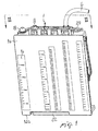
Figure 1 is a perspective view of the device according to the invention; -
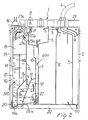
Figure 2 is a sectional view, taken along the line II-II ofFigure 1 ; -
Figure 3 is a view of a detail of the device according to the invention; -
Figures 4 and 5 are views of a detail ofFigure 2 in different functional conditions; -
Figures 6 and 7 are views of two details of the device according to the invention; -
Figures 8 and 9 are views of the detail ofFigure 7 in two different functional conditions; -
Figures 10 and 11 are views of two details according to further embodiments. - With reference to
Figures 1 to 9 , thereference numeral 1 generally designates a device, which comprises afirst collection chamber 100, delimited bywalls 2 and 3 and divided into three interconnected subchambers bypartitions 4 and 5; the first collection chamber is designed to be connected by means of a tube 6 to the thoracic cavity of a patient, so as to receive the air losses along the arrow A and the exuded liquids along the arrow B in order to collect the latter at the bottom. - A
second chamber 200, delimited by thewall 3 and by the wall formed byportions connector 8 to a suction source and is connected by means of a connectingduct 9 to thefirst chamber 100, so that the same degree of vacuum that determines the suction of the exuded liquids and of the air losses occurs therein. - While, as mentioned, the exuded liquids are collected on the bottom of the
first chamber 100, the air losses, following the arrows C and D, pass through theduct 9 and reach thesecond chamber 200, where they are directed by apartition 10, along the arrow E, toward the bottom in order to penetrate along the arrow F into a measurement device provided thereat, which is generally designated by thereference numeral 11 and is described in detail hereinafter; in output from thedevice 11 along the arrows G and H, which illustrate the crossing of atap 12 comprised within the device, the air losses arrive along the arrow I at theconnector 8 in order to be evacuated. - A
third chamber 300 is delimited by the wall formed by theportions wall 13, and the adjustment of the vacuum that occurs in the two previously described chambers occurs therein in a known manner. - In the third chamber there is in fact a
water column 14, which is typically 20 centimeters high and through which atmospheric air is made to pass by bubbling and penetrates along the arrow L at the bottom formed by a perforatedbubbling partition 15, being conveyed thereto by aduct 16 formed by apartition 17 after entering the device through aplug 18 along the arrow M, to be then evacuated along the arrow N through theconnector 8. - Since atmospheric pressure is present at the base of the
water column 14, in a portion ofspace 19 at the top there is necessarily a partial vacuum whose value is equal to the height of the column, and is therefore typically equal to 20 centimeters of water column, and such partial vacuum, shared by the two previously described chambers, is absolutely constant. - Since a
wall 1a of the device is provided with transparent regions 1b for viewing the content of the several chambers described above, a detailed description will follow with respect to the third chamber. - In order to reduce the noisiness of the device, as shown in
Figure 3 , a particular shaping has been provided for theduct 16, which conveys atmospheric air to thebubbling partition 15 provided monolithically with the structure of the device, by shaping the end portion of the bottom wall of the duct so as to form aninclined plane 20, thereby determining access of the atmospheric air to thebubbling partition 15 at thetransverse side 15a thereof, which is much longer than the front side 15b. - One thus obtains an optimum subdivision of the atmospheric air in passing through the holes of the
partition 15, with the formation of bubbles of minimum size and thus such as to ensure a good reduction of noisiness, which is directly proportional to the size of the bubbles. - Again with the goal of reducing the noisiness of the device, the sound waves in output have been subdivided by providing the
plug 18 with fourholes third chamber 300 of the device is provided with means which are capable of preventing the passage of water, due to intense bubbling of the atmospheric air in thewater column 14, through aport 21 which connects the third chamber to thesecond chamber 200 and to theconnector 8 of the suction source. From this standpoint, abase 14a of the device at thecolumn 14 has been arranged so as to be coplanar with respect to the base of asupport 22 of the device, thus obtaining the maximum spacing of the free surface of thecolumn 14 from theport 21 without causing unwanted increases in the overall vertical space occupation of the device. - For the same purpose, at the top of the portion of
space 19 there is a phase separator, which comprises abaffle 23a and aseparator 23b; the two-phase stream determined by bubbling, which comprises water, represented by the black arrow, and atmospheric air, represented by the white arrow, enters through aport 24 the duct which is delimited by the two partitions and ends with a double opening: through a port 25a, the water descends toward theunderlying column 14, separating from the current of atmospheric air that passes through aport 25b and immediately reaches, in a perfectly dry condition, theoutput port 21. - The presence of a
partition 14b makes the described separator particularly effective. - The
device 11 for measuring the air losses of the patient, which is present at the base of the second sealing chamber, is now described. -
Device 11 comprises abell 26, which has apassage port 26a at the lower end and is provided with thetap 12; at the base of the bell there is water, which in the normal operating conditions shown inFigure 2 , with thetap 12 open and therefore such as to allow the passage of the air losses along the arrows G, H, maintains its free surface at aconstant level 27. - In order to measure the air losses, the
tap 12 is closed, and so the air losses accumulate below thebell 26, gradually expelling the water through theport 26a, progressively providing situations of the type shown inFigure 4 . - The measurement of the quantity of the losses is deduced from the time taken by the air losses to completely empty the bell of water, reaching the situation of
Figure 5 , and the importance for the operator of identifying the precise instant of the end of the emptying of the water from the bell is immediately evident. - For this purpose, a
plane 28 that lies at the base of the bell has been given such an inclination as to make the region that directly faces theport 26a the lowest one. - Considering in particular
Figure 6 , it is seen that theduct 9 for connection between thefirst chamber 100 and thesecond chamber 200 of the device is formed monolithically with the structure of the device, following the same design concept that provided monolithically also thebubbling partition 15 and substantially seeks to obtain the entire device with a single mold. - Finally attention is focused on a
tube clamping plate 29, which is operated by the operator to obtain different functional conditions between the two extreme positions which are visible respectively inFigures 8 and 9 . - In order to provide an indication which is immediately perceivable without any possibility of doubt regarding the assumed position, the
plate 29 is provided with tworegions Figure 8 , theregion 29b is visible, and in the position ofFigure 9 theregion 29a is visible. -
Figure 10 shows a further embodiment of the device according to the invention related to the phase separator described with reference toFigure 2 ; with respect to the previously described embodiment, the only variation consists in that the separation partition, i.e., the partition that in such embodiment was indicated by thereference numeral 23b, is provided here in the form of acradle 30, which is connected to thewall 7c and has aport 30a for discharging the water, all the rest remaining unchanged. -
Figure 11 shows another embodiment of the device according to the invention, which relates to the bubbling partition and to the methods for feeding atmospheric air thereto which are described with reference toFigure 3 . - In this case, the bottom wall of the
duct 16 that conveys the atmospheric air to a perforatedbubbling partition 31 is flat and extends until it touches at 16a the bottom of the device, and thus the access of the air to thepartition 31 occurs by means of afront side 31a; in this solution, thepartition 31 has a differentiated calibration of the holes with a diameter which increases progressively as one moves away from theside 31a. - The described invention is susceptible of numerous other modifications and variations, all of which are within the scope of the appended claims; all the details may further be replaced with other technically equivalent elements.
- Where technical features mentioned in any claim are followed by reference signs, those reference signs have been included for the sole purpose of increasing the intelligibility of the claims and accordingly such reference signs do not have any limiting effect on the interpretation of each element identified by way of example by such reference signs.
Claims (10)
- A thoracic drainage device (1), comprising, in a monolithic structure, three interconnected contiguous chambers (100,200,300), which are adapted to be placed in partial vacuum by being connected to a source of suction which is capable of creating, within the device, a condition of vacuum which conveys away from the patient the exuded liquids and the air losses, said chambers comprising: a first chamber (100) for collecting the exuded liquids, which is adapted to be connected by means of a tube (6) to the thoracic cavity of a patient, so as to receive said exuded liquids and the air losses that exit from said cavity, a second sealing chamber (200), provided at the bottom with a device (11) for measuring said air losses, a third chamber (300) for adjusting the vacuum that occurs within the two preceding chambers (100,200), comprising a column of water (14) through which atmospheric air is made to pass which enters at the bottom formed by a perforated bubbling partition (15;31) and is conveyed thereat by a duct (16) after entering through an appropriately provided perforated plug (18) in order to be evacuated through a connector (8) which is designed to be connected to the source of suction, said bubbling partition (15;31) comprising a front side (15b;31a), and a transverse side (15a) that is arranged adjacent said duct (16) for conveying atmospheric air to said bubbling partition (15;31), the device (1) further comprising, within said monolithic structure, means adapted to reduce noisiness, which comprise a shape of the end of the duct (16) for conveying atmospheric air to said bubbling partition (15;31) that lies proximate to the bubbling partition (15;31), the shape of the end of the atmospheric air conveyance duct (16) comprising:an inclined plane (20) arranged at the rear of the bottom wall of the atmospheric air conveyance duct (16) such that the transverse side (15a) of said bubbling partition (15), at which access of the atmospheric air to said bubbling partition (15) is allowed, is longer than the front side (15b) of said bubbling partition (15), and the holes of the bubbling partition all having the same dimensions; orthe bottom wall (16a) of the duct (16) for conveying the atmospheric air to the bubbling partition (31) is extended in a flat shape to the bottom of the device, so as to allow access of the atmospheric air to said bubbling partition (31) at the front side (31a) thereof, a differentiated calibration of the holes of the bubbling partition (31), with a diameter which increases progressively as one moves away from said front side (3 1a), being provided.
- The device (1) according to claim 1, characterized in that the bubbling partition (15;31) is provided monolithically with the structure of said device.
- The device (1) according to one or more of the preceding claims, characterized in that at the top of the third chamber (300) there is, in said monolithic structure, a separator (23a,23b,24,25a,25b) for the two phases constituted by water and atmospheric air which are mixed together in the stream that exits as a consequence of bubbling from the free surface of the water column (14) that is present in said third chamber (300), with consequent fall of the water onto said column (14) and exit of the atmospheric air from said chamber (300) toward the suction source.
- The device (1) according to claim 3, characterized in that the separator of the two phases constituted by water and atmospheric air comprises, at the top, a baffle (23a) which is adapted to delimit, with an underlying partition (23b), a duct (24) which receives, at the inlet, the stream that comprises said phases mixed together, and has a double outlet port (25a,25b), one of said ports (25a) being adapted to make the water fall back toward the underlying column (14), while the other port (25b) is adapted to send the atmospheric air toward the suction source.
- The device (1) according to one or more of the preceding claims, characterized in that the perforated plug (18) for the inflow of the atmospheric air is provided with more than two holes (18a-d).
- The device (1) according to one or more of the preceding claims, characterized in that the base (14a) of said device, at the column of water (14) that is present in the third chamber (300), is arranged coplanar with the base of the support (22) of said device.
- The device (1) according to one or more of the preceding claims, characterized in that the base plane (28) of a bell (26) comprised within the device (11) for measuring air losses has such an inclination as to make the region that faces directly a port (26a) provided at the lower end of said bell (26) the lowest region.
- The device (1) according to one or more of the preceding claims, characterized in that a duct (9) for connection between the first chamber (100) and the second chamber (200) is provided monolithically with the structure of said device.
- The device (1) according to one or more of the preceding claims, comprising a tube clamping plate (29) which is adapted to be actuated by an operator between two extreme positions, which correspond to different functional features, characterized in that said plate (29) has two regions (29a,29b) with different colors which are designed to be visible selectively in said extreme positions.
- The device (1) according to one or more of the preceding claims, characterized in that a single monolithic structure comprises all the parts which do not move with respect to each other and are potentially uniform in terms of material.
Applications Claiming Priority (1)
| Application Number | Priority Date | Filing Date | Title |
|---|---|---|---|
| IT001648A ITMI20071648A1 (en) | 2007-08-08 | 2007-08-08 | THORACIC DRAINAGE DEVICE. |
Publications (3)
| Publication Number | Publication Date |
|---|---|
| EP2022513A2 EP2022513A2 (en) | 2009-02-11 |
| EP2022513A3 EP2022513A3 (en) | 2009-02-25 |
| EP2022513B1 true EP2022513B1 (en) | 2011-04-20 |
Family
ID=40010921
Family Applications (1)
| Application Number | Title | Priority Date | Filing Date |
|---|---|---|---|
| EP08160455A Active EP2022513B1 (en) | 2007-08-08 | 2008-07-15 | Silent thoracic drainage device |
Country Status (4)
| Country | Link |
|---|---|
| EP (1) | EP2022513B1 (en) |
| AT (1) | ATE506087T1 (en) |
| DE (1) | DE602008006308D1 (en) |
| IT (1) | ITMI20071648A1 (en) |
Families Citing this family (1)
| Publication number | Priority date | Publication date | Assignee | Title |
|---|---|---|---|---|
| ITMI20071649A1 (en) * | 2007-08-08 | 2009-02-09 | Eurosets Srl | THORACIC DRAINAGE DEVICE. |
Family Cites Families (4)
| Publication number | Priority date | Publication date | Assignee | Title |
|---|---|---|---|---|
| US3683913A (en) * | 1970-10-05 | 1972-08-15 | Deknatel Inc | Underwater drainage apparatus with air flow meters |
| US4988342A (en) * | 1987-03-02 | 1991-01-29 | Atrium Medical Corporation | Improved fluid recovery system |
| US4772277A (en) * | 1987-08-20 | 1988-09-20 | Vanderbilt University | Chest cavity evacuation apparatus with resettable air volume meter |
| ITMI20062291A1 (en) * | 2006-11-28 | 2008-05-29 | Eurosets Srl | DISPLAY AND MEASUREMENT DEVICE FOR AIR LOSSES IN THE THORACIC DRAINAGE APPLIANCE. |
-
2007
- 2007-08-08 IT IT001648A patent/ITMI20071648A1/en unknown
-
2008
- 2008-07-15 AT AT08160455T patent/ATE506087T1/en not_active IP Right Cessation
- 2008-07-15 DE DE602008006308T patent/DE602008006308D1/en active Active
- 2008-07-15 EP EP08160455A patent/EP2022513B1/en active Active
Also Published As
| Publication number | Publication date |
|---|---|
| ATE506087T1 (en) | 2011-05-15 |
| ITMI20071648A1 (en) | 2009-02-09 |
| DE602008006308D1 (en) | 2011-06-01 |
| EP2022513A2 (en) | 2009-02-11 |
| EP2022513A3 (en) | 2009-02-25 |
Similar Documents
| Publication | Publication Date | Title |
|---|---|---|
| US11185802B2 (en) | Apparatus, system and methods to divide flow | |
| US10398249B2 (en) | Cooking device with a steam-generating element | |
| ES2761399T3 (en) | Cooktop with steam extractor | |
| KR102305968B1 (en) | Inserts for down ventilation | |
| WO2009045589A4 (en) | Dialysis systems having air separation chambers with internal structures to enhance air removal | |
| CN107440484B (en) | Steam cooking accessory for heating and/or cooking food contained in a container with steam | |
| SE523331C2 (en) | Fuel tank | |
| US6056886A (en) | Water level and flow control device and skimmer box provided with this device | |
| EP2022514A2 (en) | Thoracic drainage device | |
| EP2022513A2 (en) | Silent thoracic drainage device | |
| EP0411488A1 (en) | Blood container for medical apparatus | |
| JP6647296B2 (en) | Air lift pump device and fluid container and tea brewing machine having the same | |
| AU2005209640B2 (en) | Dust-collecting apparatus and method for a vacuum cleaner | |
| CN109603315A (en) | A kind of vacuum system automatic draining device | |
| FI127472B (en) | Device to measure dewatering at various objects in a paper machine wet end, and method for carrying out this | |
| US2265650A (en) | Duplex pumping apparatus | |
| US6053039A (en) | Apparatus for the measurement of liquid flow | |
| EP2080530B1 (en) | Chest drainage device | |
| EP0961088B1 (en) | A low-velocity supply air terminal device | |
| BE1016650A3 (en) | IMPROVED DEVICE FOR DIVIDING AND / OR DRAINING VENTILATION AIR IN A BUILDING. | |
| CN220174989U (en) | A condiment measuring device | |
| EP4308860B1 (en) | Hot water heating device | |
| US7357860B1 (en) | Skimmer system | |
| EP4296584A1 (en) | Fan coil unit | |
| JP6358883B2 (en) | Cooker |
Legal Events
| Date | Code | Title | Description |
|---|---|---|---|
| PUAI | Public reference made under article 153(3) epc to a published international application that has entered the european phase |
Free format text: ORIGINAL CODE: 0009012 |
|
| PUAL | Search report despatched |
Free format text: ORIGINAL CODE: 0009013 |
|
| AK | Designated contracting states |
Kind code of ref document: A2 Designated state(s): AT BE BG CH CY CZ DE DK EE ES FI FR GB GR HR HU IE IS IT LI LT LU LV MC MT NL NO PL PT RO SE SI SK TR |
|
| AX | Request for extension of the european patent |
Extension state: AL BA MK RS |
|
| AK | Designated contracting states |
Kind code of ref document: A3 Designated state(s): AT BE BG CH CY CZ DE DK EE ES FI FR GB GR HR HU IE IS IT LI LT LU LV MC MT NL NO PL PT RO SE SI SK TR |
|
| AX | Request for extension of the european patent |
Extension state: AL BA MK RS |
|
| 17P | Request for examination filed |
Effective date: 20090728 |
|
| 17Q | First examination report despatched |
Effective date: 20090828 |
|
| AKX | Designation fees paid |
Designated state(s): AT BE BG CH CY CZ DE DK EE ES FI FR GB GR HR HU IE IS IT LI LT LU LV MC MT NL NO PL PT RO SE SI SK TR |
|
| GRAP | Despatch of communication of intention to grant a patent |
Free format text: ORIGINAL CODE: EPIDOSNIGR1 |
|
| GRAS | Grant fee paid |
Free format text: ORIGINAL CODE: EPIDOSNIGR3 |
|
| GRAA | (expected) grant |
Free format text: ORIGINAL CODE: 0009210 |
|
| AK | Designated contracting states |
Kind code of ref document: B1 Designated state(s): AT BE BG CH CY CZ DE DK EE ES FI FR GB GR HR HU IE IS IT LI LT LU LV MC MT NL NO PL PT RO SE SI SK TR |
|
| REG | Reference to a national code |
Ref country code: GB Ref legal event code: FG4D |
|
| REG | Reference to a national code |
Ref country code: CH Ref legal event code: EP |
|
| REG | Reference to a national code |
Ref country code: IE Ref legal event code: FG4D |
|
| REF | Corresponds to: |
Ref document number: 602008006308 Country of ref document: DE Date of ref document: 20110601 Kind code of ref document: P |
|
| REG | Reference to a national code |
Ref country code: DE Ref legal event code: R096 Ref document number: 602008006308 Country of ref document: DE Effective date: 20110601 |
|
| REG | Reference to a national code |
Ref country code: NL Ref legal event code: VDEP Effective date: 20110420 |
|
| LTIE | Lt: invalidation of european patent or patent extension |
Effective date: 20110420 |
|
| PG25 | Lapsed in a contracting state [announced via postgrant information from national office to epo] |
Ref country code: HR Free format text: LAPSE BECAUSE OF FAILURE TO SUBMIT A TRANSLATION OF THE DESCRIPTION OR TO PAY THE FEE WITHIN THE PRESCRIBED TIME-LIMIT Effective date: 20110420 Ref country code: NO Free format text: LAPSE BECAUSE OF FAILURE TO SUBMIT A TRANSLATION OF THE DESCRIPTION OR TO PAY THE FEE WITHIN THE PRESCRIBED TIME-LIMIT Effective date: 20110720 Ref country code: LT Free format text: LAPSE BECAUSE OF FAILURE TO SUBMIT A TRANSLATION OF THE DESCRIPTION OR TO PAY THE FEE WITHIN THE PRESCRIBED TIME-LIMIT Effective date: 20110420 Ref country code: PT Free format text: LAPSE BECAUSE OF FAILURE TO SUBMIT A TRANSLATION OF THE DESCRIPTION OR TO PAY THE FEE WITHIN THE PRESCRIBED TIME-LIMIT Effective date: 20110822 Ref country code: SE Free format text: LAPSE BECAUSE OF FAILURE TO SUBMIT A TRANSLATION OF THE DESCRIPTION OR TO PAY THE FEE WITHIN THE PRESCRIBED TIME-LIMIT Effective date: 20110420 |
|
| PG25 | Lapsed in a contracting state [announced via postgrant information from national office to epo] |
Ref country code: ES Free format text: LAPSE BECAUSE OF FAILURE TO SUBMIT A TRANSLATION OF THE DESCRIPTION OR TO PAY THE FEE WITHIN THE PRESCRIBED TIME-LIMIT Effective date: 20110731 Ref country code: SI Free format text: LAPSE BECAUSE OF FAILURE TO SUBMIT A TRANSLATION OF THE DESCRIPTION OR TO PAY THE FEE WITHIN THE PRESCRIBED TIME-LIMIT Effective date: 20110420 Ref country code: GR Free format text: LAPSE BECAUSE OF FAILURE TO SUBMIT A TRANSLATION OF THE DESCRIPTION OR TO PAY THE FEE WITHIN THE PRESCRIBED TIME-LIMIT Effective date: 20110721 Ref country code: IS Free format text: LAPSE BECAUSE OF FAILURE TO SUBMIT A TRANSLATION OF THE DESCRIPTION OR TO PAY THE FEE WITHIN THE PRESCRIBED TIME-LIMIT Effective date: 20110820 Ref country code: AT Free format text: LAPSE BECAUSE OF FAILURE TO SUBMIT A TRANSLATION OF THE DESCRIPTION OR TO PAY THE FEE WITHIN THE PRESCRIBED TIME-LIMIT Effective date: 20110420 Ref country code: BE Free format text: LAPSE BECAUSE OF FAILURE TO SUBMIT A TRANSLATION OF THE DESCRIPTION OR TO PAY THE FEE WITHIN THE PRESCRIBED TIME-LIMIT Effective date: 20110420 Ref country code: FI Free format text: LAPSE BECAUSE OF FAILURE TO SUBMIT A TRANSLATION OF THE DESCRIPTION OR TO PAY THE FEE WITHIN THE PRESCRIBED TIME-LIMIT Effective date: 20110420 Ref country code: LV Free format text: LAPSE BECAUSE OF FAILURE TO SUBMIT A TRANSLATION OF THE DESCRIPTION OR TO PAY THE FEE WITHIN THE PRESCRIBED TIME-LIMIT Effective date: 20110420 Ref country code: CY Free format text: LAPSE BECAUSE OF FAILURE TO SUBMIT A TRANSLATION OF THE DESCRIPTION OR TO PAY THE FEE WITHIN THE PRESCRIBED TIME-LIMIT Effective date: 20110420 |
|
| PG25 | Lapsed in a contracting state [announced via postgrant information from national office to epo] |
Ref country code: MT Free format text: LAPSE BECAUSE OF FAILURE TO SUBMIT A TRANSLATION OF THE DESCRIPTION OR TO PAY THE FEE WITHIN THE PRESCRIBED TIME-LIMIT Effective date: 20110420 Ref country code: NL Free format text: LAPSE BECAUSE OF FAILURE TO SUBMIT A TRANSLATION OF THE DESCRIPTION OR TO PAY THE FEE WITHIN THE PRESCRIBED TIME-LIMIT Effective date: 20110420 |
|
| PG25 | Lapsed in a contracting state [announced via postgrant information from national office to epo] |
Ref country code: EE Free format text: LAPSE BECAUSE OF FAILURE TO SUBMIT A TRANSLATION OF THE DESCRIPTION OR TO PAY THE FEE WITHIN THE PRESCRIBED TIME-LIMIT Effective date: 20110420 Ref country code: CZ Free format text: LAPSE BECAUSE OF FAILURE TO SUBMIT A TRANSLATION OF THE DESCRIPTION OR TO PAY THE FEE WITHIN THE PRESCRIBED TIME-LIMIT Effective date: 20110420 |
|
| PLBE | No opposition filed within time limit |
Free format text: ORIGINAL CODE: 0009261 |
|
| STAA | Information on the status of an ep patent application or granted ep patent |
Free format text: STATUS: NO OPPOSITION FILED WITHIN TIME LIMIT |
|
| PG25 | Lapsed in a contracting state [announced via postgrant information from national office to epo] |
Ref country code: SK Free format text: LAPSE BECAUSE OF FAILURE TO SUBMIT A TRANSLATION OF THE DESCRIPTION OR TO PAY THE FEE WITHIN THE PRESCRIBED TIME-LIMIT Effective date: 20110420 Ref country code: MC Free format text: LAPSE BECAUSE OF NON-PAYMENT OF DUE FEES Effective date: 20110731 Ref country code: PL Free format text: LAPSE BECAUSE OF FAILURE TO SUBMIT A TRANSLATION OF THE DESCRIPTION OR TO PAY THE FEE WITHIN THE PRESCRIBED TIME-LIMIT Effective date: 20110420 Ref country code: RO Free format text: LAPSE BECAUSE OF FAILURE TO SUBMIT A TRANSLATION OF THE DESCRIPTION OR TO PAY THE FEE WITHIN THE PRESCRIBED TIME-LIMIT Effective date: 20110420 Ref country code: DK Free format text: LAPSE BECAUSE OF FAILURE TO SUBMIT A TRANSLATION OF THE DESCRIPTION OR TO PAY THE FEE WITHIN THE PRESCRIBED TIME-LIMIT Effective date: 20110420 |
|
| 26N | No opposition filed |
Effective date: 20120123 |
|
| REG | Reference to a national code |
Ref country code: IE Ref legal event code: MM4A |
|
| REG | Reference to a national code |
Ref country code: DE Ref legal event code: R097 Ref document number: 602008006308 Country of ref document: DE Effective date: 20120123 |
|
| PG25 | Lapsed in a contracting state [announced via postgrant information from national office to epo] |
Ref country code: IE Free format text: LAPSE BECAUSE OF NON-PAYMENT OF DUE FEES Effective date: 20110715 |
|
| REG | Reference to a national code |
Ref country code: CH Ref legal event code: PL |
|
| PG25 | Lapsed in a contracting state [announced via postgrant information from national office to epo] |
Ref country code: CH Free format text: LAPSE BECAUSE OF NON-PAYMENT OF DUE FEES Effective date: 20120731 Ref country code: LI Free format text: LAPSE BECAUSE OF NON-PAYMENT OF DUE FEES Effective date: 20120731 |
|
| PG25 | Lapsed in a contracting state [announced via postgrant information from national office to epo] |
Ref country code: LU Free format text: LAPSE BECAUSE OF NON-PAYMENT OF DUE FEES Effective date: 20110715 |
|
| PG25 | Lapsed in a contracting state [announced via postgrant information from national office to epo] |
Ref country code: BG Free format text: LAPSE BECAUSE OF FAILURE TO SUBMIT A TRANSLATION OF THE DESCRIPTION OR TO PAY THE FEE WITHIN THE PRESCRIBED TIME-LIMIT Effective date: 20110720 |
|
| PG25 | Lapsed in a contracting state [announced via postgrant information from national office to epo] |
Ref country code: TR Free format text: LAPSE BECAUSE OF FAILURE TO SUBMIT A TRANSLATION OF THE DESCRIPTION OR TO PAY THE FEE WITHIN THE PRESCRIBED TIME-LIMIT Effective date: 20110420 |
|
| PG25 | Lapsed in a contracting state [announced via postgrant information from national office to epo] |
Ref country code: HU Free format text: LAPSE BECAUSE OF FAILURE TO SUBMIT A TRANSLATION OF THE DESCRIPTION OR TO PAY THE FEE WITHIN THE PRESCRIBED TIME-LIMIT Effective date: 20110420 |
|
| REG | Reference to a national code |
Ref country code: DE Ref legal event code: R082 Ref document number: 602008006308 Country of ref document: DE Representative=s name: SCHAUMBURG & PARTNER PATENTANWAELTE GBR, DE Ref country code: DE Ref legal event code: R082 Ref document number: 602008006308 Country of ref document: DE Representative=s name: SCHAUMBURG UND PARTNER PATENTANWAELTE MBB, DE |
|
| REG | Reference to a national code |
Ref country code: FR Ref legal event code: PLFP Year of fee payment: 9 |
|
| PGFP | Annual fee paid to national office [announced via postgrant information from national office to epo] |
Ref country code: GB Payment date: 20160727 Year of fee payment: 9 |
|
| REG | Reference to a national code |
Ref country code: FR Ref legal event code: PLFP Year of fee payment: 10 |
|
| PGFP | Annual fee paid to national office [announced via postgrant information from national office to epo] |
Ref country code: AT Payment date: 20170525 Year of fee payment: 19 |
|
| GBPC | Gb: european patent ceased through non-payment of renewal fee |
Effective date: 20170715 |
|
| PG25 | Lapsed in a contracting state [announced via postgrant information from national office to epo] |
Ref country code: GB Free format text: LAPSE BECAUSE OF NON-PAYMENT OF DUE FEES Effective date: 20170715 |
|
| PG25 | Lapsed in a contracting state [announced via postgrant information from national office to epo] |
Ref country code: FR Free format text: LAPSE BECAUSE OF NON-PAYMENT OF DUE FEES Effective date: 20180731 |
|
| REG | Reference to a national code |
Ref country code: DE Ref legal event code: R119 Ref document number: 602008006308 Country of ref document: DE |
|
| PG25 | Lapsed in a contracting state [announced via postgrant information from national office to epo] |
Ref country code: DE Free format text: LAPSE BECAUSE OF NON-PAYMENT OF DUE FEES Effective date: 20200201 |
|
| P01 | Opt-out of the competence of the unified patent court (upc) registered |
Effective date: 20230527 |
|
| PGFP | Annual fee paid to national office [announced via postgrant information from national office to epo] |
Ref country code: IT Payment date: 20250722 Year of fee payment: 18 |