EP2020949B1 - Orthodontic bracket with rotary ligating cover - Google Patents
Orthodontic bracket with rotary ligating cover Download PDFInfo
- Publication number
- EP2020949B1 EP2020949B1 EP07776538.6A EP07776538A EP2020949B1 EP 2020949 B1 EP2020949 B1 EP 2020949B1 EP 07776538 A EP07776538 A EP 07776538A EP 2020949 B1 EP2020949 B1 EP 2020949B1
- Authority
- EP
- European Patent Office
- Prior art keywords
- bracket
- ligating cover
- rotary ligating
- cover
- rotary
- Prior art date
- Legal status (The legal status is an assumption and is not a legal conclusion. Google has not performed a legal analysis and makes no representation as to the accuracy of the status listed.)
- Active
Links
Images


Classifications
-
- A—HUMAN NECESSITIES
- A61—MEDICAL OR VETERINARY SCIENCE; HYGIENE
- A61C—DENTISTRY; APPARATUS OR METHODS FOR ORAL OR DENTAL HYGIENE
- A61C7/00—Orthodontics, i.e. obtaining or maintaining the desired position of teeth, e.g. by straightening, evening, regulating, separating, or by correcting malocclusions
- A61C7/12—Brackets; Arch wires; Combinations thereof; Accessories therefor
- A61C7/14—Brackets; Fixing brackets to teeth
-
- A—HUMAN NECESSITIES
- A61—MEDICAL OR VETERINARY SCIENCE; HYGIENE
- A61C—DENTISTRY; APPARATUS OR METHODS FOR ORAL OR DENTAL HYGIENE
- A61C7/00—Orthodontics, i.e. obtaining or maintaining the desired position of teeth, e.g. by straightening, evening, regulating, separating, or by correcting malocclusions
- A61C7/12—Brackets; Arch wires; Combinations thereof; Accessories therefor
- A61C7/28—Securing arch wire to bracket
- A61C7/285—Locking by rotation
-
- A—HUMAN NECESSITIES
- A61—MEDICAL OR VETERINARY SCIENCE; HYGIENE
- A61C—DENTISTRY; APPARATUS OR METHODS FOR ORAL OR DENTAL HYGIENE
- A61C7/00—Orthodontics, i.e. obtaining or maintaining the desired position of teeth, e.g. by straightening, evening, regulating, separating, or by correcting malocclusions
- A61C7/12—Brackets; Arch wires; Combinations thereof; Accessories therefor
-
- A—HUMAN NECESSITIES
- A61—MEDICAL OR VETERINARY SCIENCE; HYGIENE
- A61C—DENTISTRY; APPARATUS OR METHODS FOR ORAL OR DENTAL HYGIENE
- A61C7/00—Orthodontics, i.e. obtaining or maintaining the desired position of teeth, e.g. by straightening, evening, regulating, separating, or by correcting malocclusions
- A61C7/12—Brackets; Arch wires; Combinations thereof; Accessories therefor
- A61C7/14—Brackets; Fixing brackets to teeth
- A61C7/16—Brackets; Fixing brackets to teeth specially adapted to be cemented to teeth
Definitions
- This disclosure relates to self-locking or ligatureless orthodontic brackets. More particularly, this disclosure relates to self-ligating orthodontic brackets each having a rotary ligating cover for retaining an archwire therein.
- Orthodontic treatment generally comprises dental work to correct irregularities of the teeth or of the relation of the teeth to surrounding anatomy.
- the irregularities may involve malocclusions with varying degrees of severity.
- Class 1 malocclusions for example, involve spacing irregularities such as excessive crowding or diastema (a gap between two adjacent teeth).
- Class 2 malocclusions involve overbite conditions where the upper anterior teeth project labially over the lower anterior teeth.
- Class 3 malocclusions in contrast, involve underbite conditions where the upper anterior teeth close within the lingual side of the lower anterior teeth.
- treatment typically involves installation of braces or mechanical aids for repositioning the teeth into correct orthodontic alignment.
- Braces generally include orthodontic brackets configured for attachment to the labial or lingual surfaces of the teeth or for attachment to metallic bands secured around the teeth.
- the brackets typically include archwire slots within which a flexible yet resilient archwire may be engaged.
- Each bracket is typically bonded to the tooth surface so that the bracket's archwire slot is oriented for engagement with the archwire.
- Various techniques are used for orienting the brackets.
- an edgewise appliance comprises braces whereby each bracket is oriented and bonded to the tooth so that the archwire slot is perpendicular to the long axis of the root of the tooth.
- a straight-wire appliance includes braces whereby each bracket is oriented and bonded to the tooth so that the archwire slot is parallel to the occlusal plane (the plane of the biting surfaces of the teeth).
- the archwire is typically a curved metallic wire having a rectangular or circular cross section that is bent or twisted prior to engagement with the brackets.
- the memory or restoring force exerted by the archwire upon the brackets serves to move the teeth into the desired alignment.
- the orthodontist periodically adjusts the shape of the archwire (as well as the configuration of other attachments such as elastic bands and so forth) to achieve the correct orthodontic alignment.
- Most brackets in current use incorporate tie wings or extensions that project upwardly and downwardly in a gingival-occlusal orientation and require the use of ligatures or ligating modules to hold the archwire within the archwire slots.
- the ligatures or ligating modules are typically donut-shaped elastomeric rings or wires that are stretched around or twisted around the tie wings.
- ligatures or ligating modules presents a number of inherent disadvantages, some of which are mentioned herein.
- the small size of the ligatures or ligating modules requires substantial time for installation of the archwire. Because the orthodontist will typically make numerous adjustments to the archwire throughout orthodontic treatment, the orthodontist will likely remove and replace the ligatures or ligating modules numerous times. Hygiene is another problem since the use of ligatures or ligating modules increases the areas where food particles may be trapped. Further, with movement due to chewing or other activities, the ligatures or ligating modules may become detached altogether, allowing the archwire to disengage from the archwire slots.
- Ligatures or ligating modules also present other limitations in terms of the forces exerted upon the brackets.
- the labial or outward force that may be applied to a tooth having a bracket bonded to its labial surface is limited to the strength of the ligature or ligating module in the labial direction.
- the force that may be applied in the lingual direction is not so constrained (because the force is applied against the bracket structure rather than the ligature or ligation module).
- bracket systems generally rely on active ligation using elastomeric or wire ligatures wrapped about the tie wings of the bracket to hold the archwire into the archwire slot.
- the two areas that hold the archwire most securely are the mesial and distal ends of the bracket where the elastomeric or wire ligatures make contact with the archwire, binding the archwire. This binding creates friction during orthodontic tooth movement and consequently increases the forces needed for leveling and sliding tooth movement during treatment.
- US6,168,428 discloses a pre-engaging orthodontic bracket including a body having a lingual surface for attachment to a tooth, a pair of laterally spaced gingival tie wings and a pair or laterally spaced occlusal tie wings.
- the gingival and occlusal tie wings project from a labial surface of the body.
- An archwire slot extends mesiodistally across the body and between the gingival and occlusal tie wings at opposed mesio and distal sides of the body to accommodate an archwire.
- a shutter is movable between an open position in which placement and removal of an archwire is facilitated, and a closed position in which placement and removal of an archwire is inhibited.
- a locking mechanism locks the shutter in the closed position.
- one aspect of the present invention provides a self-ligating orthondontic bracket having: a mounting base for attachment to a tooth surface; a pair of tie wings extending from said base and defining an archwire slot between said tie wings, said archwire slot being sized for receiving an orthodontic archwire; a rotary ligating cover selectively rotatable between an open position permitting access to said archwire slot and a closed position covering said archwire slot, said rotary ligating cover being rotatable about an axis that is perpendicular to said tooth surface; and one or more locking mechanisms comprising cooperatively engaging features located on said cover and said base for holding said rotary ligating cover in a closed position, characterised in that said one or more locking mechanisms comprise one or more locking tabs formed upon one of said rotary ligating cover and said base, said one or more locking tabs aligned in coplanar relation to said rotary ligating cover and cooperatively mating with cutout portions in the other of said rotary ligating cover and said base.
- FIG. 1 illustrates an isometric view of a self-ligating orthodontic bracket 100 according to one embodiment of the invention.
- the self-ligating orthodontic bracket 100 includes a mounting base 105 for attachment to a tooth surface, an archwire slot 110 formed upon the mounting base 105 and sized for receiving an orthodontic archwire (not shown), and a rotary ligating cover 115 (shown in a closed position) for retaining an orthodontic archwire within the archwire slot 110 .
- the rotary ligating cover 115 comprises a plate (as shown) that rotates about an axial member such as a retaining pin 120 positioned in an eccentric manner, i.e.
- the rotary ligating cover 115 preferably includes one or more coplanar resilient retention features (or locking mechanisms) 125 for holding the rotary ligating cover 115 in a closed position thereby retaining an orthodontic archwire within the archwire slot 110 .
- the one or more coplanar resilient retention features 125 comprise resilient portions of the rotary ligating cover 115 suitably formed to allow coplanar deflection and subsequent locking of one or more protruding surfaces of the rotary ligating cover 115 with one or more corresponding indentations 130 .
- the resilient retention features 125 have been designed to deflect inward, toward the axis of the retaining pin 120 , for lockable engagement between one or more protruding surfaces (or locking tabs) of the rotary ligating cover 115 and one or more cooperatively mating indentations 130. In this configuration, the resilient retention features 125 deflect and engage with the mating indentations 130 in directions coplanar with the rotary ligating cover 115 .
- the self-ligating orthodontic bracket 100 includes one or more orthodontic tool features such as an outer surface feature 145 of the rotary ligating cover 115.
- the outer surface feature 145 may be a protruding ridge (as shown), a recessed groove (not shown), a circular recessed area, or any of a number of suitable shapes and configurations that improve the ease of use of the bracket 100 .
- an orthodontic tool such as an explorer or scaler is used with the outer surface feature 145 to rotatably open or close the rotary ligating cover 115 to expose or cover, respectively, the archwire slot 110 .
- pliers or another orthodontic tool may be used with the outer surface feature 145 (perhaps along with one side of the bracket 100 ) to close the rotary ligating cover 115 .
- the outer surface feature 145 alone or in combination with the retaining pin 120 and other visual aspects of the bracket 100 , preferably provides a centerline for the bracket 100 useful to aid the orthodontist in the placement of the bracket 100 upon the patient's tooth.
- the self-ligating orthodontic bracket 100 preferably includes rounded edges and chamfered archwire slot ends 150 to improve comfort for the patient wearing the orthodontic appliance.
- the rotary ligating cover 115, the exterior pan head shape of the retaining pin 120 , and other features which define the outer surfaces of the bracket 100 opposite the mounting base 105 preferably comprise smooth and rounded shapes to improve patient comfort and minimize the overall side profile or outward dimension of the bracket 100 from the bonding surface of the mounting base 105 .
- the outer surfaces of the one or more indentations 130 and the neighboring edges 160 therebetween are coplanar and flush with the outer surfaces of the rotary ligating cover 115 and, in particular, with the outer surfaces of the one or more resilient retention features 125 and the neighboring or adjacent outer surfaces therebetween.
- FIG. 2 illustrates an exploded isometric view of a self-ligating orthodontic bracket 200 having a bracket base 205 , rotary ligating cover 210 , and retaining pin 215, according to one embodiment of the invention.
- the rotary ligating cover 210 is rotatably fastened to the bracket base 205 using retaining pin 215 inserted through a hole 220 in the rotating cover 210 and journalled into a corresponding hole 225 in a tie wing 230 formed on one side of the archwire slot 235 .
- the outward surface 240 of the bracket 205 opposite the tooth mounting surface 245 and upon which the rotary ligating cover 210 may be rotated when fastened to the bracket 205 , preferably encompasses substantially all of the outward facing surface area of the tie wing 230 , and an axis of rotation 250 of the rotary ligating cover 210 extends through the outward surface 240 .
- a coplanar portion 255 of the opposing tie wing 260 on the other side of the archwire slot 235 receives the bottom surface of the rotary ligating cover 210 so that the rotary ligating cover 210 , when in a closed position, covers substantially the full length of the archwire slot 235 .
- the outward surface 240 incorporates concentric circular recesses 265 and 270 for limiting rotation of the rotary ligating cover 210 due to asymmetries of the bracket 200 .
- the rotary ligating cover 210 need not be symmetrical about its centerline, the centerline formed by the through hole 220 and (as shown) the outer surface feature 275 .
- circular recess 265 is used in combination with engagement of locking tabs 280 with cooperatively mating cutout portions or indentations 285 to establish a closed position for the rotary ligating cover 210 when the rotary ligating cover 210 is rotated in a clockwise direction about the axis of rotation 250 as viewed from the outward surface of the bracket 200 looking toward the tooth mounting surface 245 .
- the rotary ligating cover 210 may incorporate a protruding nub on its lower surface that tracks within the concentric circular recesses 265 and 270 .
- the rotary ligating cover 210 is closed to cover the archwire slot 235 by turning the rotary ligating cover 210 in a clockwise direction until the looking tabs 280 engage with the cooperatively mating indentations 285 formed upon the tie wing 260 and the protruding nub (not shown) reaches the end of (or just beyond the end of) the circular recess 265 .
- the rotary ligating cover 210 is opened to expose the archwire slot 235 by turning the rotary ligating cover 210 in a counterclockwise direction whereby the protruding nub moves first within the circular recess 265 and then the circular recess 270 until the archwire slot 235 is fully exposed.
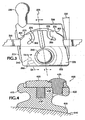
- FIG. 3 illustrates an exemplary frontal view of a self-ligating orthodontic bracket 300 engaged with an archwire 310 .
- the bracket 300 may be mounted to the labial (front) surface of a tooth as part of a typical bracket system. Or, alternatively, the bracket 300 may be mounted on the lingual (back) of a tooth surface as part of a lingual or "hidden" bracket system.
- the frontal profile of the bracket 300 is designed for use on particular tooth surfaces.
- the bracket 300 is designed to have a particular rhomboid or parallelogram profile for bonding to a particular tooth, such as one of the upper or lower centrals, laterals, cuspids, bicuspids, molars, and so on.
- the archwire 310 is retained within the self-ligating bracket 300 so that the archwire 310 runs in a mesial-distal orientation, parallel to the occlusal surface (the cutting or incisal edge) of a tooth.
- Other orientations may be used with the bracket 300 .
- this orientation is typical of a straight-wire (or Roth) appliance whereby crown angulation and crown inclination are engineered into the bracket 300 thereby allowing use of an archwire that is "straight" or parallel to the cutting edge of each tooth (when the teeth are positioned in correct orthodontic alignment).
- Crown angulation is generally the mesial-distal to gingival-occlusal orientation of the tooth and is affected by the mesial-distal orientation of the archwire slot (or slot tip). Crown inclination is generally the labial-lingual to gingival-occlusal orientation of the tooth and is affected by the rotational orientation of the archwire slot (or slot torque) along the mesial-distal (or archwire) axis.
- the bracket 300 shown in FIG. 3 has an engineered slot tip 320 , which is the angular offset between the centerline 325 of the bracket 300 and a line perpendicular to a mesial-distal line that is parallel with the archwire 310.
- the bracket 300 is bonded to a tooth surface so that the centerline 325 of the bracket 300 is aligned with the gingival-occlusal axis (or long axis) of the tooth's clinical crown.
- a straight-wire appliance typically includes individually engineered brackets with each bracket having the desired crown inclination (slot torque) and crown angulation (slot tip) for a particular tooth
- a standard edgewise appliance typically includes brackets having a rectangular profile and an orientation such that the centerline of the bracket is aligned along the gingival-occlusal axis (or long axis) of the clinical crown and perpendicular with the archwire slot.
- the brackets in a standard edgewise appliance have archwire slots that are not parallel to the incisal edges of the teeth (when the teeth are positioned in correct orthodontic alignment). Instead, the archwire is angled, bent, and twisted to define the desired position of the teeth.
- brackets are fabricated for a particular patient by prescription.
- the brackets are engineered to include the appropriate slot torque and slot tip for each individual tooth for the particular patient.
- specifically engineered brackets are fabricated for the upper left central, the upper left lateral, the upper left cuspid, and so forth moving distally toward the upper left molars (using Palmer's notation for designating individual teeth).
- Each bracket typically incorporates a particular slot torque and slot tip as well as other features as may be needed.
- the bracket for the upper left cuspid includes a slot tip 320 of, perhaps, 9° and include a ball hook 330 for use with elastics or other features of the orthodontic appliance.
- the mounting base 315 of the bracket 300 is sized to fit a particular tooth surface.
- the mounting base 315 may be wider at the incisal end of the tooth to match the shape of the tooth surface.
- the bracket 300 is bonded to the surface of a tooth, or, alternatively, to a band assembly which is attached to the tooth.
- the bracket 300 is oriented so that the rotary ligating cover 335 pivots about an axial member 340 positioned on the tie wing on the side of the archwire slot closest to the incisal end of the tooth surface (and opposite the gingival end).
- the bracket may be oppositely oriented so that the rotary ligating cover 335 pivots about an axial member 340 positioned on the on the gingival side of the archwire slot.
- the rotary ligating cover 335 follows the overall rhomboid or parallelogram shape of the bracket 300 and is not symmetrical about its centerline 325 .
- a protruding nub or rotation stop 345 may be formed upon the underside of the rotary ligating cover 335 designed to track within concentric circular recesses 350 and 355 when the rotary ligating cover 335 pivots about the axial member 340 .
- the rotation stop 345 slides into and follows the first circular recess 350 , and, with further rotation, follows freely within the second circular recess 355 .
- the rotation stop 345 follows freely within the second circular recess 355 and then follows within the first circular recess 350 until sliding up to and slightly beyond the end of the first circular recess 350 .
- the resilient retention features (or mechanisms) 360 deflect inward, toward the axial member 340 until locking tabs 365 engage with cooperatively mating cutout portions (or indentations) 370 .
- the resilient retention features 360 resemble coplanar fingers within the rotary ligating cover 335 , whereby relief channels 375 permit flexing of at least portions of the resilient retention features 360 adjacent to the locking tabs 365 .
- the orientation of concentric circular recesses 350 and 355 , and associated rotation stop 345 may be reversed such that the rotary ligating cover 335 is opened in a clockwise direction of rotation and closed in a counterclockwise direction of rotation.
- the positions of the locking tabs 365 and corresponding indentations 370 may be reversed, according to one embodiment, yet still provide the intended function.
- the bracket 300 includes one or more locking tabs (such as locking tabs 365 ) aligned in coplanar relation to the rotary ligating cover 335 and cooperatively mating with cutout portions in the rotary ligating cover.
- the one or more locking tabs are formed upon the bracket base, and the cooperatively mating cutout portions, to which the locking tabs engage when the ligating cover is In a closed position, may be formed upon the rotary ligating cover.
- FIG. 4 illustrates a sectional view (such as through centerline 325 in FIG. 3 ) of a self-ligating orthodontic bracket 400 with a rotary ligating cover 405 in a dosed position, according to one embodiment.
- the bracket 400 includes a mounting base 410 and a pair of tie wings 415 and 420 formed thereon and extending outward, away from the mounting base 410 , and defining an archwire slot 425 therebetween.
- the archwire slot 425 is sized for receiving an orthodontic archwire 430
- the rotary ligating cover 405 is selectively rotatable between a closed position (as shown) for securably retaining the archwire 430 within the archwire slot 425 and an open position (not shown) for permitting access to the archwire slot 420.
- the rotary ligating cover 405 rotates about an axial member such as a retaining pin 435 positioned on one side of the bracket 400 such as on one of the tie wings 420.
- the retaining pin 435 shown incorporates a pan head extending over the outward surface of the rotary ligating cover 405 and a lower portion journalled or fastenably attached into a receiving hole or recess area in the tie wing 420.
- the retaining pin 435 is dimensioned with a smaller diameter that is inserted into the receiving hole in the tie wing 420 and a larger diameter about which the rotary ligating cover 405 may slidably rotate.
- the smaller diameter permits a press-fit operation for retaining the rotary ligating cover 405 to the bracket 400 whereby the smaller diameter of the retaining pin (or dowel) 435 is forcibly pressed into the receiving hole in the tie wing 420 .
- a retaining pin having a single diameter may be used, perhaps with precision fastening equipment to ensure that the retaining pin is able to rotate freely about the retaining pin.
- the pair of tie wings (as shown, 415 and 420 ) generally extend transverse to the archwire slot 425 with one tie wing ( i.e. , 415 ) extending from the archwire slot 425 in a gingival direction and the other ( i.e ., 420 ) extending from the archwire slot 425 in an occlusal direction.
- the tie wings 415 and 420 provide additional utility and flexibility for the orthodontist in applications where the use of standard elastomeric ligatures or other attachments requiring tie wings is desired.
- the use of standard elastomeric ligatures creates friction between the archwire and the elastomeric ligature.
- the friction, or active engagement, with the archwire 430 allows for additional forces to be applied to a tooth surface 440 bonded to the bracket 400 .
- active engagement with the archwire 430 is used to urge tooth movement along the mesial-distal (or archwire) axis (to increase or decrease spacing between adjacent teeth).
- Active engagement with the archwire 430 may also be used to increase the forces applied to change crown angulation (affected by slot tip) and crown inclination (affected by slot torque).
- the self-ligating bracket 400 relies on passive engagement with the archwire 430 .
- the archwire 430 With passive engagement, the archwire 430 is not forcibly restrained within the archwire slot 425 and is instead allowed to move within the archwire slot 425 .
- Such brackets may comprise a passive or so-called frictionless bracket system and do not require traditional ligatures or ligating modules. In such systems, the archwire 430 is free to slide within the archwire slot 425 along the mesial-distal axis.
- crown inclination is generally the labial-lingual to gingival-occlusal orientation of the tooth and is affected by the rotational orientation of the archwire slot 430 along the mesial-distal axis.
- An axial (or sectional) view of the bracket 400 along the mesial-distal axis is shown in FIG. 4 .
- the archwire slot 425 is shown angled (or rotated) slightly such that the labial-lingual sides of the archwire slot 425 (which are normal to the rotary ligating cover 405 ) are not perpendicular (or not normal) to the tooth surface 440 .
- This is a typical rotational orientation for the archwire slot used in a straight-wire appliance where slot torque is engineered into the bracket.
- a standard edgewise appliance typically includes an archwire slot with sides perpendicular to the mounting surface of the tooth.
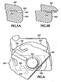
- FIGs. 5A-5B sectional views are illustrated showing the rotary ligating cover 335 upon a bracket base 315 (or a tie wing 500 thereon) in closed and partially open positions, according to various embodiments of the invention.
- FIG. 5A depicts the sectional view indicated in FIG. 3 and shows the rotary ligating cover 335 in a closed position with the rotation stop 345 slightly beyond the end of the circular recess 350 .
- the slight separation 505 between the rotary ligating cover 335 and the mating surface of the tie wing 500 provides additional retention forces for holding the rotary ligating cover 335 in a closed position.
- the frictional forces between the rotation stop 345 and the outward surface of the tie wing 500 and the frictional forces involving the axial member (not shown) retaining the rotary ligating cover 335 provide additional retention forces beyond the retention forces provided by engagement of other locking features associated with the rotary ligating cover 335 , such as, for example, coplanar locking tabs along the edge surface of the ligating cover 335 .
- FIG. 5A Another embodiment involves a sectional view as in FIG. 5A , having the rotary ligating cover 335 in a closed position with the rotation stop 345 formed upon the lower surface of the ligating cover 335 and positioned outside of or beyond the end of the circular recess 350 .
- the rotation stop 345 may be seated within a cooperatively mating cutout portion (not shown) of the outward surface of the tie wing 500 and, thereby, holding the rotary ligating cover 335 in a closed position.
- FIG. 5B depicts the sectional view with the rotary ligating cover 335 in a partially open position with the rotation stop 345 shown tracking within the circular recess 350 .
- the rotary ligating cover 335 has been partially opened (in a counterclockwise direction) whereby the rotation stop 345 has dropped into the circular recess 350 .
- the rotation stop 345 leaves the circular recess 350 , as illustrated in FIG. 6 .
- Also shown in FIG. 6 are the relative positions of locking tabs 365 and their cooperatively mating cutout portions (or indentations) 370, according to one embodiment.
- the locking tabs 365 become unseated from their corresponding indentations 370 allowing the rotary ligating cover 335 to rotate more freely.
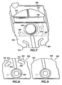
- FIG. 7 illustrates a top view of a self-ligating orthodontic bracket, according to one embodiment, as in FIG. 6 , except that the rotary ligating cover 335 is in an open position, exposing the archwire slot 700 formed upon the bracket base 315 .
- the rotary ligating cover 335 has been rotated in a counterclockwise direction until the archwire slot 700 is fully exposed.
- the rotation stop 345 has tracked within the circular recess 355 .
- the rotation stop 345 moves up against an end in the circular recess 355 (not shown) for stopping the counterclockwise rotation of the rotary ligating cover 335 when the archwire slot 700 becomes fully exposed.
- FIG. 8 illustrates a top view of a rotary ligating cover 800 according to an alternate embodiment of the invention.
- the rotary ligating cover 800 incorporates relief areas 805 cut out behind the locking tabs 810 leaving resilient retention features 815 that deflect inward, in directions coplanar with the rotary ligating cover and toward the axial member 820 about which the rotary ligating cover is able to pivot
- the resilient retention features 815 deflect inward in directions perpendicular with the pivot axis of the axial member 815 , allowing the locking tabs 810 to engage with cooperatively mating cut out portions or indentations (not shown) in the bracket base.
- FIG. 9 illustrates a top view of a rotary ligating cover 900 according to another alternate embodiment of the invention.
- the rotary ligating cover 900 incorporates one or more locking tabs 905 which engage with cooperatively mating cutout portions or indentations (not shown) in the bracket base when the rotary ligating cover 900 is rotated into a dosed position.
- the one or more locking tabs 905 are preferably aligned in coplanar relation to rotary ligating cover 900 as shown, cooperatively mate with cutout portions in the bracket base (not shown), and are capable of exerting retention forces in a direction coplanar with the rotary ligating cover and, thereby, holding the rotary ligating cover in a closed position.
- FIG. 10 illustrates a sectional view of a self-ligating orthodontic bracket 1000 (along its centerline as in FIG. 4 ) with a rotary ligating cover 1005 in a closed position, according to an alternate embodiment of the invention.
- bracket 1000 comprises a mounting base 1010 for mounting the bracket 1000 upon a tooth surface 1040 and a pair of tie wings 1015 and 1020 formed upon the mounting base 1010, extending outward therefrom and defining an archwire slot 1025 therebetween.
- the rotary ligating cover 1005 is rotatably fastened upon one of the tie wings 1020 and is capable of rotatably and securely closing over the archwire slot 1025 and an archwire 1030 therein.
- the rotary ligating cover 1005 is rotatably fastened using a retaining pin 1035 that fits into a bushing 1045 formed upon the tie wing 1020 .
- the retaining pin 1035 may be any fastener with a pan head or similar head structure capable of retaining the rotary ligating cover 1005 by overlapping the outward surface of the bushing 1045 and a portion of the outward surface of the rotary ligating cover 1005 extending outward from the bushing 1045 .
- the retaining pin 1035 includes one or more axial ribs 1050 for improving interference fit and retention forces of the retaining pin 1035 within the bushing 1045 and hole or recess extending below the bushing 1045 toward the bracket mounting base 1010 .
- FIG. 11 illustrates a sectional view of a self-ligating orthodontic bracket 1100 (along its centerline as in FIG. 4 ) with a rotary ligating cover 1105 in a closed position, according to another alternate embodiment of the invention.
- bracket 1100 comprises a mounting base 1110 for mounting the bracket 1100 upon a tooth surface 1140 and a pair of tie wings 1115 and 1120 formed upon the mounting base 1110 , extending outward therefrom and defining an archwire slot 1125 therebetween.
- the rotary ligating cover 1105 is rotatably fastened upon one of the tie wings 1120 and is capable of rotatably and securely closing over the archwire slot 1125 and an archwire 1130 therein.
- FIG. 11 shows the sectional view prior to the coining operation. During the coining operation, some of the material comprising the stud 1135 is displaced inward, toward the bracket mounting base 1110, and radially outward from the stud 1135 to overlap an annular portion 1145 of the outward surface of the rotary ligating cover 1005 immediately adjacent to the stud 1135.
- a recess such as a conical recess 1150 is formed upon the outward facing surface of the stud 1135 (as shown).
- other scribe lines or recess areas may be included as may be needed depending upon the particular coining process and materials chosen for the bracket 1100 .
- the self-ligating orthodontic bracket described herein comprises any of a wide variety of materials suitable for use in an orthodontic appliance. Such materials have commonly included plastics, ceramics, stainless steel, titanium, or other metal alloys.
- the bracket preferably comprises a biocompatible material with corrosion resistive properties, and the bracket preferably comprises materials which are formed into the structures shown yet maintain suitable strength characteristics for retaining commonly used orthodontic archwires or other components of an orthodontic appliance.
- Nickel is the most common metal associated with contact dermatitis in orthodontics. Recent figures suggest that perhaps 10% of patients are sensitive to nickel. Nevertheless, nickel-containing metal alloys, such as nickel-titanium and stainless steel, are widely used in orthodontic appliances. Nickel-titanium alloys have nickel contents above 50% and potentially release enough nickel in the oral environment to elicit manifestations of an allergic reaction. Stainless steel has a much lower nickel content, perhaps around 8%, and, because the nickel is bound in a crystal lattice within stainless steel, the nickel is less available to react. Consequently, stainless steel orthodontic components are less likely to cause nickel hypersensitivity.
- nickel-containing metal alloys such as nickel-titanium and stainless steel
- the self-ligating orthodontic bracket described herein preferably comprises a nickel-free material.
- the bracket comprises a nickel-free cobalt-chromium alloy.
- the bracket may be cast, machined, injection molded and so on. Injection molding of plastics may be used as may be ceramic injection molding (CIM) or metal injection molding (MIM) depending upon the materials chosen.
- CIM ceramic injection molding
- MIM metal injection molding
- the bracket may comprise a molded base coupled with a molded rotary ligating cover that is coined to hold the cover to the bracket, or the bracket may comprise a molded base coupled with a molded ligating cover fastened to the bracket using a separate axial member press-fit onto the bracket.
- the bracket may comprise the assembly of a formed bracket body and a formed rotary ligating cover, the rotary ligating cover retained upon a tie wing of the bracket body following a coining operation whereby a stud protruding from the bracket body is mushroomed or coined to retain the rotary ligating cover thereon.
- a ball hook, or other components, may be welded to the bracket assembly or formed as part of the bracket body ( i.e ., as part of the molded bracket body).
Landscapes
- Health & Medical Sciences (AREA)
- Oral & Maxillofacial Surgery (AREA)
- Dentistry (AREA)
- Epidemiology (AREA)
- Life Sciences & Earth Sciences (AREA)
- Animal Behavior & Ethology (AREA)
- General Health & Medical Sciences (AREA)
- Public Health (AREA)
- Veterinary Medicine (AREA)
- Dental Tools And Instruments Or Auxiliary Dental Instruments (AREA)
Description
- This disclosure relates to self-locking or ligatureless orthodontic brackets. More particularly, this disclosure relates to self-ligating orthodontic brackets each having a rotary ligating cover for retaining an archwire therein.
- Orthodontic treatment generally comprises dental work to correct irregularities of the teeth or of the relation of the teeth to surrounding anatomy. The irregularities may involve malocclusions with varying degrees of severity. Class 1 malocclusions, for example, involve spacing irregularities such as excessive crowding or diastema (a gap between two adjacent teeth). Class 2 malocclusions involve overbite conditions where the upper anterior teeth project labially over the lower anterior teeth. Class 3 malocclusions, in contrast, involve underbite conditions where the upper anterior teeth close within the lingual side of the lower anterior teeth. For these and other observed irregularities, treatment typically involves installation of braces or mechanical aids for repositioning the teeth into correct orthodontic alignment.
- Braces generally include orthodontic brackets configured for attachment to the labial or lingual surfaces of the teeth or for attachment to metallic bands secured around the teeth. The brackets typically include archwire slots within which a flexible yet resilient archwire may be engaged. Each bracket is typically bonded to the tooth surface so that the bracket's archwire slot is oriented for engagement with the archwire. Various techniques are used for orienting the brackets. For example, an edgewise appliance comprises braces whereby each bracket is oriented and bonded to the tooth so that the archwire slot is perpendicular to the long axis of the root of the tooth. Alternatively, a straight-wire appliance includes braces whereby each bracket is oriented and bonded to the tooth so that the archwire slot is parallel to the occlusal plane (the plane of the biting surfaces of the teeth).
- The archwire is typically a curved metallic wire having a rectangular or circular cross section that is bent or twisted prior to engagement with the brackets. The memory or restoring force exerted by the archwire upon the brackets serves to move the teeth into the desired alignment. Throughout the duration of orthodontic treatment, the orthodontist periodically adjusts the shape of the archwire (as well as the configuration of other attachments such as elastic bands and so forth) to achieve the correct orthodontic alignment. Most brackets in current use incorporate tie wings or extensions that project upwardly and downwardly in a gingival-occlusal orientation and require the use of ligatures or ligating modules to hold the archwire within the archwire slots. The ligatures or ligating modules are typically donut-shaped elastomeric rings or wires that are stretched around or twisted around the tie wings.
- The use of such ligatures or ligating modules presents a number of inherent disadvantages, some of which are mentioned herein. The small size of the ligatures or ligating modules requires substantial time for installation of the archwire. Because the orthodontist will typically make numerous adjustments to the archwire throughout orthodontic treatment, the orthodontist will likely remove and replace the ligatures or ligating modules numerous times. Hygiene is another problem since the use of ligatures or ligating modules increases the areas where food particles may be trapped. Further, with movement due to chewing or other activities, the ligatures or ligating modules may become detached altogether, allowing the archwire to disengage from the archwire slots.
- Ligatures or ligating modules also present other limitations in terms of the forces exerted upon the brackets. For example, the labial or outward force that may be applied to a tooth having a bracket bonded to its labial surface is limited to the strength of the ligature or ligating module in the labial direction. On the same tooth, the force that may be applied in the lingual direction is not so constrained (because the force is applied against the bracket structure rather than the ligature or ligation module).
- Traditional bracket systems generally rely on active ligation using elastomeric or wire ligatures wrapped about the tie wings of the bracket to hold the archwire into the archwire slot. The two areas that hold the archwire most securely are the mesial and distal ends of the bracket where the elastomeric or wire ligatures make contact with the archwire, binding the archwire. This binding creates friction during orthodontic tooth movement and consequently increases the forces needed for leveling and sliding tooth movement during treatment.
- By contrast, passive self-ligating (or so-called frictionless) bracket systems, or bracket systems that do not require traditional ligatures or ligating modules, have been developed which rely on a principle that forces employed to reposition teeth should not overwhelm the supporting periodontium and facial musculature. Forces applied should instead be minimized to a level just large enough to stimulate cellular activity and, thus, tooth movement without unnecessarily disturbing the vascular supply to the periodontium.
- Several self-locking or self-ligating (ligatureless) orthodontic brackets have been designed. However, most of those have complex designs, incorporating features requiring prohibitively expensive machining operations or comprising multiple separate parts, which in turn increases the number of failure modes for such brackets. Other designs have been rejected in the marketplace due to poor quality or poor design, a lack of available features, difficulty of use, or other factors.
-
US6,168,428 discloses a pre-engaging orthodontic bracket including a body having a lingual surface for attachment to a tooth, a pair of laterally spaced gingival tie wings and a pair or laterally spaced occlusal tie wings. The gingival and occlusal tie wings project from a labial surface of the body. An archwire slot extends mesiodistally across the body and between the gingival and occlusal tie wings at opposed mesio and distal sides of the body to accommodate an archwire. A shutter is movable between an open position in which placement and removal of an archwire is facilitated, and a closed position in which placement and removal of an archwire is inhibited. A locking mechanism locks the shutter in the closed position. - What is needed, therefore, is an orthodontic bracket that incorporates a self-ligating capability and that offers a different style of bracket than those available today.
- Accordingly, one aspect of the present invention provides a self-ligating orthondontic bracket having: a mounting base for attachment to a tooth surface; a pair of tie wings extending from said base and defining an archwire slot between said tie wings, said archwire slot being sized for receiving an orthodontic archwire; a rotary ligating cover selectively rotatable between an open position permitting access to said archwire slot and a closed position covering said archwire slot, said rotary ligating cover being rotatable about an axis that is perpendicular to said tooth surface; and one or more locking mechanisms comprising cooperatively engaging features located on said cover and said base for holding said rotary ligating cover in a closed position, characterised in that said one or more locking mechanisms comprise one or more locking tabs formed upon one of said rotary ligating cover and said base, said one or more locking tabs aligned in coplanar relation to said rotary ligating cover and cooperatively mating with cutout portions in the other of said rotary ligating cover and said base.
- The foregoing and other objectives, features, and advantages of the invention will be more readily understood upon consideration of the following detailed description of the invention taken in conjunction with the accompanying drawings.
- For a more complete understanding of the present invention, the drawings herein illustrate examples of the invention. The drawings, however, do not limit the scope of the invention. Similar references in the drawings indicate similar elements.
-
FIG. 1 illustrates an isometric view of a self-ligating orthodontic bracket according to one embodiment of the invention. -
FIG. 2 illustrates an exploded isometric view of a self-ligating orthodontic bracket having a bracket base, rotary ligating cover, and retaining pin, according to one embodiment of the invention. -
FIG. 3 illustrates an exemplary frontal view of a self-ligating orthodontic bracket engaged with an archwire. -
FIG. 4 illustrates a sectional view of a self-ligating orthodontic bracket with a rotary ligating cover in a closed position, according to one embodiment of the invention. -
FIGs. 5A-5B illustrate sectional views of a rotary ligating cover upon a bracket base in closed and partially open positions, according to various embodiments of the invention. -
FIG. 6 illustrates a top view of a self-ligating orthodontic bracket with a rotary ligating cover in a partially open position, according to one embodiment of the invention. -
FIG. 7 illustrates a top view of a self-ligating orthodontic bracket with a rotary ligating cover in an open position, exposing an archwire slot within a bracket base, according to one embodiment of the invention. -
FIG. 8 illustrates a top view of a rotary ligating cover according to an alternate embodiment of the invention. -
FIG. 9 illustrates a top view of a rotary ligating cover according to another alternate embodiment of the invention. -
FIG. 10 illustrates a sectional view of a self-ligating orthodontic bracket with a rotary ligating cover in a closed position, according to an alternate embodiment of the invention. -
FIG. 11 illustrates a sectional view of a self-ligating orthodontic bracket with a rotary ligating cover in a closed position, according to another alternate embodiment of the invention. - Turning now to the several drawings,
FIG. 1 illustrates an isometric view of a self-ligatingorthodontic bracket 100 according to one embodiment of the invention. The self-ligatingorthodontic bracket 100 includes amounting base 105 for attachment to a tooth surface, anarchwire slot 110 formed upon themounting base 105 and sized for receiving an orthodontic archwire (not shown), and a rotary ligating cover 115 (shown in a closed position) for retaining an orthodontic archwire within thearchwire slot 110. As will be discussed in greater detail below, therotary ligating cover 115, comprises a plate (as shown) that rotates about an axial member such as aretaining pin 120 positioned in an eccentric manner, i.e., the pivot point positioned on one side of thebracket 100, and having a pivot axis oriented perpendicular to thearchwire slot 110 and substantially normal to the tooth surface and mountingbase 105 bonded thereon. Therotary ligating cover 115 preferably includes one or more coplanar resilient retention features (or locking mechanisms) 125 for holding therotary ligating cover 115 in a closed position thereby retaining an orthodontic archwire within thearchwire slot 110. - As shown in
FIG. 1 , the one or more coplanar resilient retention features 125 comprise resilient portions of therotary ligating cover 115 suitably formed to allow coplanar deflection and subsequent locking of one or more protruding surfaces of therotary ligating cover 115 with one or morecorresponding indentations 130. Here, the resilient retention features 125 have been designed to deflect inward, toward the axis of the retainingpin 120, for lockable engagement between one or more protruding surfaces (or locking tabs) of therotary ligating cover 115 and one or more cooperativelymating indentations 130. In this configuration, the resilient retention features 125 deflect and engage with themating indentations 130 in directions coplanar with therotary ligating cover 115. Consequently, forces exerted normal to the rotary ligating cover 115 (i.e., forces in a labial-lingual direction) as may arise due to movement of an archwire retained within thearchwire slot 110, are not likely to affect the retention of the archwire within thearchwire slot 110. Thus, the self-ligatingorthodontic bracket 100 more securely retains an archwire than other bracket designs. - Also shown in
FIG. 1 , the self-ligatingorthodontic bracket 100 includes one or more orthodontic tool features such as anouter surface feature 145 of therotary ligating cover 115. Theouter surface feature 145 may be a protruding ridge (as shown), a recessed groove (not shown), a circular recessed area, or any of a number of suitable shapes and configurations that improve the ease of use of thebracket 100. For instance, an orthodontic tool such as an explorer or scaler is used with theouter surface feature 145 to rotatably open or close therotary ligating cover 115 to expose or cover, respectively, thearchwire slot 110. Likewise, pliers or another orthodontic tool may be used with the outer surface feature 145 (perhaps along with one side of the bracket 100) to close therotary ligating cover 115. Further, theouter surface feature 145, alone or in combination with the retainingpin 120 and other visual aspects of thebracket 100, preferably provides a centerline for thebracket 100 useful to aid the orthodontist in the placement of thebracket 100 upon the patient's tooth. - The self-ligating
orthodontic bracket 100 preferably includes rounded edges and chamfered archwire slot ends 150 to improve comfort for the patient wearing the orthodontic appliance. As shown and as will be depicted in many of the illustrations herein, therotary ligating cover 115, the exterior pan head shape of the retainingpin 120, and other features which define the outer surfaces of thebracket 100 opposite the mountingbase 105, preferably comprise smooth and rounded shapes to improve patient comfort and minimize the overall side profile or outward dimension of thebracket 100 from the bonding surface of the mountingbase 105. Preferably, the outer surfaces of the one ormore indentations 130 and the neighboringedges 160 therebetween are coplanar and flush with the outer surfaces of therotary ligating cover 115 and, in particular, with the outer surfaces of the one or more resilient retention features 125 and the neighboring or adjacent outer surfaces therebetween. -
FIG. 2 illustrates an exploded isometric view of a self-ligatingorthodontic bracket 200 having abracket base 205,rotary ligating cover 210, and retainingpin 215, according to one embodiment of the invention. As shown, therotary ligating cover 210 is rotatably fastened to thebracket base 205 using retainingpin 215 inserted through ahole 220 in therotating cover 210 and journalled into acorresponding hole 225 in atie wing 230 formed on one side of thearchwire slot 235. Theoutward surface 240 of thebracket 205, opposite thetooth mounting surface 245 and upon which therotary ligating cover 210 may be rotated when fastened to thebracket 205, preferably encompasses substantially all of the outward facing surface area of thetie wing 230, and an axis ofrotation 250 of therotary ligating cover 210 extends through theoutward surface 240. Acoplanar portion 255 of the opposingtie wing 260 on the other side of thearchwire slot 235 receives the bottom surface of therotary ligating cover 210 so that therotary ligating cover 210, when in a closed position, covers substantially the full length of thearchwire slot 235. - As will be described in further detail, the
outward surface 240 incorporates concentriccircular recesses rotary ligating cover 210 due to asymmetries of thebracket 200. For example, forbrackets 200 having a rhomboid or parallelogram overall shape as viewed from the outward surface of the bracket looking toward the tooth mounting surface 245 (or a frontal view), therotary ligating cover 210 need not be symmetrical about its centerline, the centerline formed by the throughhole 220 and (as shown) theouter surface feature 275. For such an asymmetricalrotary ligating cover 210,circular recess 265 is used in combination with engagement of lockingtabs 280 with cooperatively mating cutout portions orindentations 285 to establish a closed position for therotary ligating cover 210 when therotary ligating cover 210 is rotated in a clockwise direction about the axis ofrotation 250 as viewed from the outward surface of thebracket 200 looking toward thetooth mounting surface 245. As will be shown in successive views, therotary ligating cover 210 may incorporate a protruding nub on its lower surface that tracks within the concentriccircular recesses - In the embodiment shown in
FIG. 2 , therotary ligating cover 210 is closed to cover thearchwire slot 235 by turning therotary ligating cover 210 in a clockwise direction until the lookingtabs 280 engage with the cooperativelymating indentations 285 formed upon thetie wing 260 and the protruding nub (not shown) reaches the end of (or just beyond the end of) thecircular recess 265. Therotary ligating cover 210 is opened to expose thearchwire slot 235 by turning therotary ligating cover 210 in a counterclockwise direction whereby the protruding nub moves first within thecircular recess 265 and then thecircular recess 270 until thearchwire slot 235 is fully exposed. - Next,
FIG. 3 illustrates an exemplary frontal view of a self-ligatingorthodontic bracket 300 engaged with anarchwire 310. Thebracket 300 may be mounted to the labial (front) surface of a tooth as part of a typical bracket system. Or, alternatively, thebracket 300 may be mounted on the lingual (back) of a tooth surface as part of a lingual or "hidden" bracket system. As will be discussed further, the frontal profile of thebracket 300 is designed for use on particular tooth surfaces. For example, thebracket 300 is designed to have a particular rhomboid or parallelogram profile for bonding to a particular tooth, such as one of the upper or lower centrals, laterals, cuspids, bicuspids, molars, and so on. - The
archwire 310 is retained within the self-ligatingbracket 300 so that the archwire 310 runs in a mesial-distal orientation, parallel to the occlusal surface (the cutting or incisal edge) of a tooth. Other orientations may be used with thebracket 300. However, this orientation is typical of a straight-wire (or Roth) appliance whereby crown angulation and crown inclination are engineered into thebracket 300 thereby allowing use of an archwire that is "straight" or parallel to the cutting edge of each tooth (when the teeth are positioned in correct orthodontic alignment). Crown angulation is generally the mesial-distal to gingival-occlusal orientation of the tooth and is affected by the mesial-distal orientation of the archwire slot (or slot tip). Crown inclination is generally the labial-lingual to gingival-occlusal orientation of the tooth and is affected by the rotational orientation of the archwire slot (or slot torque) along the mesial-distal (or archwire) axis. - The
bracket 300 shown inFIG. 3 has an engineeredslot tip 320, which is the angular offset between thecenterline 325 of thebracket 300 and a line perpendicular to a mesial-distal line that is parallel with thearchwire 310. In orthodontic practice, thebracket 300 is bonded to a tooth surface so that thecenterline 325 of thebracket 300 is aligned with the gingival-occlusal axis (or long axis) of the tooth's clinical crown. - Whereas a straight-wire appliance typically includes individually engineered brackets with each bracket having the desired crown inclination (slot torque) and crown angulation (slot tip) for a particular tooth, other techniques may be used which require different orientations. For example, a standard edgewise appliance typically includes brackets having a rectangular profile and an orientation such that the centerline of the bracket is aligned along the gingival-occlusal axis (or long axis) of the clinical crown and perpendicular with the archwire slot. Typically, the brackets in a standard edgewise appliance have archwire slots that are not parallel to the incisal edges of the teeth (when the teeth are positioned in correct orthodontic alignment). Instead, the archwire is angled, bent, and twisted to define the desired position of the teeth.
- As commonly practiced in orthodontic treatment, brackets are fabricated for a particular patient by prescription. The brackets are engineered to include the appropriate slot torque and slot tip for each individual tooth for the particular patient. For example, specifically engineered brackets are fabricated for the upper left central, the upper left lateral, the upper left cuspid, and so forth moving distally toward the upper left molars (using Palmer's notation for designating individual teeth). Each bracket typically incorporates a particular slot torque and slot tip as well as other features as may be needed. For instance, the bracket for the upper left cuspid includes a
slot tip 320 of, perhaps, 9° and include aball hook 330 for use with elastics or other features of the orthodontic appliance. - Still referring to
FIG. 3 , the mountingbase 315 of thebracket 300 is sized to fit a particular tooth surface. For example, the mountingbase 315 may be wider at the incisal end of the tooth to match the shape of the tooth surface. Thebracket 300 is bonded to the surface of a tooth, or, alternatively, to a band assembly which is attached to the tooth. Thebracket 300 is oriented so that therotary ligating cover 335 pivots about anaxial member 340 positioned on the tie wing on the side of the archwire slot closest to the incisal end of the tooth surface (and opposite the gingival end). However, the bracket may be oppositely oriented so that therotary ligating cover 335 pivots about anaxial member 340 positioned on the on the gingival side of the archwire slot. - For the
particular bracket 300 shown inFIG. 3 , therotary ligating cover 335 follows the overall rhomboid or parallelogram shape of thebracket 300 and is not symmetrical about itscenterline 325. A protruding nub or rotation stop 345 may be formed upon the underside of therotary ligating cover 335 designed to track within concentriccircular recesses rotary ligating cover 335 pivots about theaxial member 340. For example, as therotary ligating cover 335 is rotated in a counterclockwise direction from the dosed position shown, the rotation stop 345 slides into and follows the firstcircular recess 350, and, with further rotation, follows freely within the secondcircular recess 355. Likewise, as therotary ligating cover 335 is rotated in a clockwise (or closing) direction, the rotation stop 345 follows freely within the secondcircular recess 355 and then follows within the firstcircular recess 350 until sliding up to and slightly beyond the end of the firstcircular recess 350. - As the
rotary ligating cover 335 rotates in a clockwise direction about theaxial member 340, the resilient retention features (or mechanisms) 360 deflect inward, toward theaxial member 340 until lockingtabs 365 engage with cooperatively mating cutout portions (or indentations) 370. In the embodiment shown, the resilient retention features 360 resemble coplanar fingers within therotary ligating cover 335, wherebyrelief channels 375 permit flexing of at least portions of the resilient retention features 360 adjacent to the lockingtabs 365. - As will be appreciated, in one embodiment the orientation of concentric
circular recesses rotary ligating cover 335 is opened in a clockwise direction of rotation and closed in a counterclockwise direction of rotation. Likewise, the positions of the lockingtabs 365 andcorresponding indentations 370 may be reversed, according to one embodiment, yet still provide the intended function. Thebracket 300 includes one or more locking tabs (such as locking tabs 365) aligned in coplanar relation to therotary ligating cover 335 and cooperatively mating with cutout portions in the rotary ligating cover. In other words, the one or more locking tabs are formed upon the bracket base, and the cooperatively mating cutout portions, to which the locking tabs engage when the ligating cover is In a closed position, may be formed upon the rotary ligating cover. - Next,
FIG. 4 illustrates a sectional view (such as throughcenterline 325 inFIG. 3 ) of a self-ligatingorthodontic bracket 400 with arotary ligating cover 405 in a dosed position, according to one embodiment. Thebracket 400 includes a mountingbase 410 and a pair oftie wings base 410, and defining anarchwire slot 425 therebetween. Thearchwire slot 425 is sized for receiving anorthodontic archwire 430, and therotary ligating cover 405 is selectively rotatable between a closed position (as shown) for securably retaining thearchwire 430 within thearchwire slot 425 and an open position (not shown) for permitting access to thearchwire slot 420. Therotary ligating cover 405 rotates about an axial member such as a retainingpin 435 positioned on one side of thebracket 400 such as on one of thetie wings 420. The retainingpin 435 shown incorporates a pan head extending over the outward surface of therotary ligating cover 405 and a lower portion journalled or fastenably attached into a receiving hole or recess area in thetie wing 420. As shown, the retainingpin 435 is dimensioned with a smaller diameter that is inserted into the receiving hole in thetie wing 420 and a larger diameter about which therotary ligating cover 405 may slidably rotate. The smaller diameter, according to one embodiment, permits a press-fit operation for retaining therotary ligating cover 405 to thebracket 400 whereby the smaller diameter of the retaining pin (or dowel) 435 is forcibly pressed into the receiving hole in thetie wing 420. However, other configurations may be used. For example, a retaining pin having a single diameter may be used, perhaps with precision fastening equipment to ensure that the retaining pin is able to rotate freely about the retaining pin. - The pair of tie wings (as shown, 415 and 420) generally extend transverse to the
archwire slot 425 with one tie wing (i.e., 415) extending from thearchwire slot 425 in a gingival direction and the other (i.e., 420) extending from thearchwire slot 425 in an occlusal direction. Thetie wings archwire 430 allows for additional forces to be applied to atooth surface 440 bonded to thebracket 400. For example, active engagement with thearchwire 430 is used to urge tooth movement along the mesial-distal (or archwire) axis (to increase or decrease spacing between adjacent teeth). Active engagement with thearchwire 430 may also be used to increase the forces applied to change crown angulation (affected by slot tip) and crown inclination (affected by slot torque). - In contrast, the self-ligating
bracket 400 relies on passive engagement with thearchwire 430. With passive engagement, thearchwire 430 is not forcibly restrained within thearchwire slot 425 and is instead allowed to move within thearchwire slot 425. Such brackets may comprise a passive or so-called frictionless bracket system and do not require traditional ligatures or ligating modules. In such systems, thearchwire 430 is free to slide within thearchwire slot 425 along the mesial-distal axis. - As previously discussed, crown inclination is generally the labial-lingual to gingival-occlusal orientation of the tooth and is affected by the rotational orientation of the
archwire slot 430 along the mesial-distal axis. An axial (or sectional) view of thebracket 400 along the mesial-distal axis is shown inFIG. 4 . Here, thearchwire slot 425 is shown angled (or rotated) slightly such that the labial-lingual sides of the archwire slot 425 (which are normal to the rotary ligating cover 405) are not perpendicular (or not normal) to thetooth surface 440. This is a typical rotational orientation for the archwire slot used in a straight-wire appliance where slot torque is engineered into the bracket. A standard edgewise appliance, in contrast, typically includes an archwire slot with sides perpendicular to the mounting surface of the tooth. - Turning now to
FIGs. 5A-5B , sectional views are illustrated showing therotary ligating cover 335 upon a bracket base 315 (or atie wing 500 thereon) in closed and partially open positions, according to various embodiments of the invention.FIG. 5A depicts the sectional view indicated inFIG. 3 and shows therotary ligating cover 335 in a closed position with the rotation stop 345 slightly beyond the end of thecircular recess 350. Theslight separation 505 between therotary ligating cover 335 and the mating surface of thetie wing 500 provides additional retention forces for holding therotary ligating cover 335 in a closed position. For example, the frictional forces between the rotation stop 345 and the outward surface of thetie wing 500 and the frictional forces involving the axial member (not shown) retaining therotary ligating cover 335 provide additional retention forces beyond the retention forces provided by engagement of other locking features associated with therotary ligating cover 335, such as, for example, coplanar locking tabs along the edge surface of theligating cover 335. - Another embodiment involves a sectional view as in
FIG. 5A , having therotary ligating cover 335 in a closed position with the rotation stop 345 formed upon the lower surface of theligating cover 335 and positioned outside of or beyond the end of thecircular recess 350. However, the rotation stop 345 may be seated within a cooperatively mating cutout portion (not shown) of the outward surface of thetie wing 500 and, thereby, holding therotary ligating cover 335 in a closed position. -
FIG. 5B depicts the sectional view with therotary ligating cover 335 in a partially open position with the rotation stop 345 shown tracking within thecircular recess 350. Here, therotary ligating cover 335 has been partially opened (in a counterclockwise direction) whereby the rotation stop 345 has dropped into thecircular recess 350. - As the
rotary ligating cover 335 is opened further (still rotating in a counterclockwise direction), the rotation stop 345, in one embodiment, leaves thecircular recess 350, as illustrated inFIG. 6 . Also shown inFIG. 6 are the relative positions of lockingtabs 365 and their cooperatively mating cutout portions (or indentations) 370, according to one embodiment. As therotary ligating cover 335 opens, pivoting about theaxial member 340, the lockingtabs 365 become unseated from their correspondingindentations 370 allowing therotary ligating cover 335 to rotate more freely. -
FIG. 7 illustrates a top view of a self-ligating orthodontic bracket, according to one embodiment, as inFIG. 6 , except that therotary ligating cover 335 is in an open position, exposing thearchwire slot 700 formed upon thebracket base 315. Here, therotary ligating cover 335 has been rotated in a counterclockwise direction until thearchwire slot 700 is fully exposed. Through this portion of rotation, the rotation stop 345 has tracked within thecircular recess 355. In one embodiment, the rotation stop 345 moves up against an end in the circular recess 355 (not shown) for stopping the counterclockwise rotation of therotary ligating cover 335 when thearchwire slot 700 becomes fully exposed. - As will be appreciated, variations of the self-ligating orthodontic bracket described herein may be apparent. For example,
FIG. 8 illustrates a top view of arotary ligating cover 800 according to an alternate embodiment of the invention. Therotary ligating cover 800 incorporatesrelief areas 805 cut out behind the lockingtabs 810 leaving resilient retention features 815 that deflect inward, in directions coplanar with the rotary ligating cover and toward theaxial member 820 about which the rotary ligating cover is able to pivot For example, as therotary ligating cover 800 rotates into a closed position, the resilient retention features 815 deflect inward in directions perpendicular with the pivot axis of theaxial member 815, allowing the lockingtabs 810 to engage with cooperatively mating cut out portions or indentations (not shown) in the bracket base. -
FIG. 9 illustrates a top view of arotary ligating cover 900 according to another alternate embodiment of the invention. Therotary ligating cover 900 incorporates one ormore locking tabs 905 which engage with cooperatively mating cutout portions or indentations (not shown) in the bracket base when therotary ligating cover 900 is rotated into a dosed position. The one ormore locking tabs 905 are preferably aligned in coplanar relation torotary ligating cover 900 as shown, cooperatively mate with cutout portions in the bracket base (not shown), and are capable of exerting retention forces in a direction coplanar with the rotary ligating cover and, thereby, holding the rotary ligating cover in a closed position. -
FIG. 10 illustrates a sectional view of a self-ligating orthodontic bracket 1000 (along its centerline as inFIG. 4 ) with arotary ligating cover 1005 in a closed position, according to an alternate embodiment of the invention. Similar with the bracket shown inFIG. 4 ,bracket 1000 comprises a mountingbase 1010 for mounting thebracket 1000 upon atooth surface 1040 and a pair oftie wings base 1010, extending outward therefrom and defining anarchwire slot 1025 therebetween. Therotary ligating cover 1005 is rotatably fastened upon one of thetie wings 1020 and is capable of rotatably and securely closing over thearchwire slot 1025 and anarchwire 1030 therein. However, therotary ligating cover 1005 is rotatably fastened using aretaining pin 1035 that fits into abushing 1045 formed upon thetie wing 1020. The retainingpin 1035 may be any fastener with a pan head or similar head structure capable of retaining therotary ligating cover 1005 by overlapping the outward surface of thebushing 1045 and a portion of the outward surface of therotary ligating cover 1005 extending outward from thebushing 1045. In one embodiment, the retainingpin 1035 includes one or moreaxial ribs 1050 for improving interference fit and retention forces of theretaining pin 1035 within thebushing 1045 and hole or recess extending below thebushing 1045 toward thebracket mounting base 1010. -
FIG. 11 illustrates a sectional view of a self-ligating orthodontic bracket 1100 (along its centerline as inFIG. 4 ) with arotary ligating cover 1105 in a closed position, according to another alternate embodiment of the invention. Similar with the bracket shown inFIG. 4 ,bracket 1100 comprises a mountingbase 1110 for mounting thebracket 1100 upon atooth surface 1140 and a pair oftie wings base 1110, extending outward therefrom and defining anarchwire slot 1125 therebetween. Therotary ligating cover 1105 is rotatably fastened upon one of thetie wings 1120 and is capable of rotatably and securely closing over thearchwire slot 1125 and anarchwire 1130 therein. However, therotary ligating cover 1105 is rotatably fastened about astud 1135 formed upon thetie wing 1120 and coined (or mushroomed) to retain therotary ligating cover 1105.FIG. 11 shows the sectional view prior to the coining operation. During the coining operation, some of the material comprising thestud 1135 is displaced inward, toward thebracket mounting base 1110, and radially outward from thestud 1135 to overlap anannular portion 1145 of the outward surface of therotary ligating cover 1005 immediately adjacent to thestud 1135. To facilitate the coining operation and to improve the repeatability and consistency of the overlap of theannular portion 1145 of therotary ligating cover 1105, a recess such as aconical recess 1150 is formed upon the outward facing surface of the stud 1135 (as shown). Likewise, other scribe lines or recess areas may be included as may be needed depending upon the particular coining process and materials chosen for thebracket 1100. - The self-ligating orthodontic bracket described herein comprises any of a wide variety of materials suitable for use in an orthodontic appliance. Such materials have commonly included plastics, ceramics, stainless steel, titanium, or other metal alloys. The bracket preferably comprises a biocompatible material with corrosion resistive properties, and the bracket preferably comprises materials which are formed into the structures shown yet maintain suitable strength characteristics for retaining commonly used orthodontic archwires or other components of an orthodontic appliance.
- Nickel is the most common metal associated with contact dermatitis in orthodontics. Recent figures suggest that perhaps 10% of patients are sensitive to nickel. Nevertheless, nickel-containing metal alloys, such as nickel-titanium and stainless steel, are widely used in orthodontic appliances. Nickel-titanium alloys have nickel contents above 50% and potentially release enough nickel in the oral environment to elicit manifestations of an allergic reaction. Stainless steel has a much lower nickel content, perhaps around 8%, and, because the nickel is bound in a crystal lattice within stainless steel, the nickel is less available to react. Consequently, stainless steel orthodontic components are less likely to cause nickel hypersensitivity.
- However, because of the remaining uncertainty regarding a particular patient's sensitivity to nickel, it is desirable to provide nickel-free orthodontic brackets to avoid nickel hypersensitivity altogether. Therefore, the self-ligating orthodontic bracket described herein preferably comprises a nickel-free material. In one embodiment, the bracket comprises a nickel-free cobalt-chromium alloy.
- Several methods are used to manufacture the self-ligating orthodontic bracket described herein. For example, the bracket may be cast, machined, injection molded and so on. Injection molding of plastics may be used as may be ceramic injection molding (CIM) or metal injection molding (MIM) depending upon the materials chosen. The bracket may comprise a molded base coupled with a molded rotary ligating cover that is coined to hold the cover to the bracket, or the bracket may comprise a molded base coupled with a molded ligating cover fastened to the bracket using a separate axial member press-fit onto the bracket. For instance, the bracket may comprise the assembly of a formed bracket body and a formed rotary ligating cover, the rotary ligating cover retained upon a tie wing of the bracket body following a coining operation whereby a stud protruding from the bracket body is mushroomed or coined to retain the rotary ligating cover thereon. A ball hook, or other components, may be welded to the bracket assembly or formed as part of the bracket body (i.e., as part of the molded bracket body).
Claims (10)
- A self-ligating orthodontic bracket (100) having:a mounting base (105) for attachment to a tooth surface;a pair of tie wings (230, 260) extending from said base (105) and defining an archwire slot (110) between said tie wings (230, 260), said archwire slot (110) being sized for receiving an orthodontic archwire (430);a rotary ligating cover (115) selectively rotatable between an open position permitting access to said archwire slot (110) and a closed position covering said archwire slot (110), said rotary ligating cover (115) being rotatable about an axis (215) that is perpendicular to said tooth surface; andone or more locking mechanisms (345, 350, 355; 365, 370) comprising cooperatively engaging features located on said cover (115) and said base (110) for holding said rotary ligating cover (115) in a closed position,characterised in that said one or more locking mechanisms (345, 350, 355; 365,370) comprise one or more locking tabs (365) formed upon one of said rotary ligating cover (115) and said base (105), said one or more locking tabs (365) aligned in coplanar relation to said rotary ligating cover (115) and cooperatively mating with cutout portions (370) in the other of said rotary ligating cover (115) and said base (105).
- The bracket of claim 1, further comprising at least one resilient retention mechanism (360, 375) adjacent to said one or more locking tabs (365) and aligned in coplanar relation to said rotary ligating cover (115), said at least one resilient retention mechanism (360, 375) capable of exerting retention forces in a direction coplanar with said rotary ligating cover (115).
- The bracket of claim 2, wherein said at least one resilient retention mechanism (360, 375) includes one or more relief channels (375) permitting flexing of at least portions of said resilient retention mechanism (360, 375) adjacent to said one or more locking tabs (365).
- The bracket of any of claims 1 to 3, wherein said one or more locking mechanisms comprise one or more rotational stops (345) formed upon one of a lower surface of said rotary ligating cover (115) and an outward surface of said base (105), said one or more rotational stops (345) cooperatively mating with cutout portions (350,355) in the other of said lower surface of said rotary ligating cover (115) and said outward surface of said base (105).
- The bracket of claim 4, wherein said bracket (100) further comprises one or more concentric circular recesses (350, 355) formed upon one of said lower surface of said rotary ligating cover (115) and said outward surface of said base (105) within which said one or more rotational stops (345) track when said rotary ligating cover (115) is rotated, said one or more concentric circular recesses (350, 355) defining an opening direction and a closing direction of said rotary ligating cover (115).
- The bracket of any of claims 1 to 5 wherein said rotary ligating cover (115) comprises a plate eccentrically rotatably mounted on an axial member (215) journalled into a first one of said tie wings (230).
- The bracket of claim 6, wherein rotary ligating cover (115) is rotatably closable over said archwire slot (110) and cooperatively mating with outward surfaces in a second one of said tie wings (260).
- The bracket of any of claims 6 or 7, wherein said axial member (215) comprises a retaining pin (215) for rotatably fastening said rotary ligating cover (115) to a hole (250) in said first one of said tie wings (230) sized for receiving said retaining pin (215).
- The bracket of any of claims 6 or 7, wherein said axial member comprises a retaining pin (1035) for rotatably fastening said rotary ligating cover (1005) to a hole within a bushing (1045) formed upon said first one of said tie wings (1020), said hole sized for receiving said retaining pin (1035).
- The bracket of any of claims 6 or 7, wherein said axial member comprises a stud (1135) formed upon said first one of said tie wings (1120) and coined to rotatably fasten said rotary ligating cover (1105) to said first one of said tie wings (1120).
Applications Claiming Priority (2)
| Application Number | Priority Date | Filing Date | Title |
|---|---|---|---|
| US11/417,685 US7585171B2 (en) | 2006-05-04 | 2006-05-04 | Orthodontic bracket with rotary ligating cover |
| PCT/US2007/010501 WO2007130378A2 (en) | 2006-05-04 | 2007-04-30 | Orthodontic bracket with rotary ligating cover |
Publications (3)
| Publication Number | Publication Date |
|---|---|
| EP2020949A2 EP2020949A2 (en) | 2009-02-11 |
| EP2020949A4 EP2020949A4 (en) | 2012-05-02 |
| EP2020949B1 true EP2020949B1 (en) | 2013-07-03 |
Family
ID=38661573
Family Applications (1)
| Application Number | Title | Priority Date | Filing Date |
|---|---|---|---|
| EP07776538.6A Active EP2020949B1 (en) | 2006-05-04 | 2007-04-30 | Orthodontic bracket with rotary ligating cover |
Country Status (7)
| Country | Link |
|---|---|
| US (2) | US7585171B2 (en) |
| EP (1) | EP2020949B1 (en) |
| JP (2) | JP2009535160A (en) |
| KR (1) | KR101307190B1 (en) |
| AU (1) | AU2007248695B2 (en) |
| CA (1) | CA2651425C (en) |
| WO (1) | WO2007130378A2 (en) |
Families Citing this family (58)
| Publication number | Priority date | Publication date | Assignee | Title |
|---|---|---|---|---|
| JP2501891Y2 (en) | 1990-01-31 | 1996-06-19 | 株式会社島津製作所 | Pyrolysis device |
| US7695277B1 (en) | 2004-10-28 | 2010-04-13 | Rmo, Inc. | Orthodontic bracket with frangible cover mechanism |
| US20090155734A1 (en) * | 2006-04-19 | 2009-06-18 | Damon Dwight H | Orthodontic bracket |
| US7704072B2 (en) | 2006-04-19 | 2010-04-27 | Ormco Corporation | Orthodontic bracket |
| US9554875B2 (en) | 2006-09-07 | 2017-01-31 | Rmo, Inc. | Method for producing a customized orthodontic appliance |
| US8979528B2 (en) | 2006-09-07 | 2015-03-17 | Rmo, Inc. | Customized orthodontic appliance method and system |
| WO2008031060A2 (en) | 2006-09-07 | 2008-03-13 | Rmo, Inc. | Reduced-friction buccal tube and method of use |
| US20100151401A1 (en) * | 2006-10-10 | 2010-06-17 | Ormco Corporation | Orthodontic implant cap and orthodontic treatment assembly including same |
| BRPI0813295B8 (en) * | 2007-06-28 | 2021-06-22 | Ormco Corp | orthodontic bracket |
| US8469704B2 (en) * | 2007-06-28 | 2013-06-25 | Ormco Corporation | Self-ligating orthodontic bracket and devices for deploying same |
| WO2010107567A1 (en) | 2009-03-16 | 2010-09-23 | Rmo, Inc. | Orthodontic bracket having an archwire channel and archwire retaining mechanism |
| US11219507B2 (en) | 2009-03-16 | 2022-01-11 | Orthoamerica Holdings, Llc | Customized orthodontic appliance and method |
| US8235714B2 (en) * | 2009-08-12 | 2012-08-07 | World Class Technology Corporation | Convertible buccal tube orthodontic bracket |
| US20110081622A1 (en) * | 2009-10-05 | 2011-04-07 | Cameron Mashouf | Self-ligating bracket with universal application |
| US8162660B2 (en) | 2009-11-20 | 2012-04-24 | Robert T Rudman | Rotating clip orthodontic bracket |
| US8287274B2 (en) * | 2010-05-25 | 2012-10-16 | World Class Technology Corporation | Tool for orthodontic appliance |
| US8371846B2 (en) | 2010-06-03 | 2013-02-12 | Mohannad Kishi | Self-adjustable, self-ligating orthodontic bracket |
| US9345558B2 (en) | 2010-09-03 | 2016-05-24 | Ormco Corporation | Self-ligating orthodontic bracket and method of making same |
| US9615897B2 (en) | 2010-09-10 | 2017-04-11 | Ormco Corporation | Self-ligating orthodontic bracket |
| US8113828B1 (en) * | 2010-09-14 | 2012-02-14 | Greenfield Raphael L | Orthodontic bracket |
| US8465279B2 (en) | 2010-09-14 | 2013-06-18 | World Class Technology Corporation | Orthodontic bracket |
| JP2014507173A (en) | 2010-12-08 | 2014-03-27 | ストライト インダストリーズ エルティディ | Gripping device for orthodontics |
| BR112013020242A2 (en) | 2011-02-11 | 2016-10-18 | Orthoarm Inc | orthodontic support |
| CA2835409C (en) * | 2011-05-12 | 2019-05-14 | Rmo, Inc. | Orthodontic appliance with encoded information formed in the base |
| US20120315593A1 (en) * | 2011-06-13 | 2012-12-13 | Asociacion Metropolitana Para La Educacion | Adjustable orthodontic bracket |
| US8696352B2 (en) | 2011-09-15 | 2014-04-15 | Lanfried Ortho Technology, Llc | Intra-oral appliance and methods of using same |
| US9744000B2 (en) | 2011-09-15 | 2017-08-29 | Lanfried Ortho Technology, Llc | Intra-oral appliance and methods of using same |
| USD847349S1 (en) | 2011-09-22 | 2019-04-30 | Rmo, Inc. | Orthodontic lock with flange |
| EP2644150B1 (en) | 2012-03-28 | 2019-01-23 | Orthoarm, Inc. | Active self-ligating bracket |
| US9585733B2 (en) | 2012-03-28 | 2017-03-07 | Orthoarm, Inc. | Orthodontic bracket with angled, curved shutter |
| US8992214B2 (en) | 2012-11-13 | 2015-03-31 | Mem Dental Technology Co., Ltd. | Orthodontic self-ligating brackets |
| US9089386B2 (en) * | 2012-11-16 | 2015-07-28 | World Class Technology Corporation | Self-ligating bracket with sliding cover |
| USD726318S1 (en) | 2013-01-17 | 2015-04-07 | Rmo, Inc. | Dental instrument for a self-ligating orthodontic clip |
| JP6391681B2 (en) | 2013-06-14 | 2018-09-19 | オルムコ コーポレイション | Self-ligating orthodontic bracket with rotatable closure member |
| US9486299B2 (en) | 2013-09-20 | 2016-11-08 | Brandon Owen | Bracket system |
| USD721811S1 (en) | 2013-10-29 | 2015-01-27 | Rmo, Inc. | Orthodontic bracket |
| US9943383B2 (en) * | 2014-12-19 | 2018-04-17 | Ormco Corporation | Biased pivoting slide orthodontic bracket |
| US10182885B2 (en) | 2015-10-29 | 2019-01-22 | Mem Dental Technology Co., Ltd | Self-ligating bracket |
| US10085824B2 (en) | 2015-10-30 | 2018-10-02 | Ortho Organizers, Inc. | Self ligating orthodontic bracket |
| US11116607B2 (en) * | 2015-12-21 | 2021-09-14 | Premier Orthodontic Designs Lllp | Archwire for use with a passive ligating orthodontic bracket system |
| US10327868B2 (en) | 2016-09-16 | 2019-06-25 | Ortho Organizers, Inc. | Self ligating orthodontic bracket with coplanar spring |
| US11612457B2 (en) | 2017-03-22 | 2023-03-28 | World Class Technology Corporation | Adjustable hook for orthodontic brackets |
| AU2018240124C1 (en) * | 2017-03-22 | 2023-08-17 | World Class Technology Corporation | Adjustable hook for orthodontic brackets |
| US10575928B2 (en) | 2017-09-21 | 2020-03-03 | Brandon Owen | Orthodontic bracket retention anchor |
| KR101881863B1 (en) | 2017-10-28 | 2018-07-25 | 주식회사 바이오세텍 | Switching tool for self ligation bracket for dental treatment |
| CN107874850B (en) * | 2017-10-31 | 2024-06-14 | 陈建文 | Self-locking bracket for orthodontics |
| US11331165B2 (en) | 2018-03-27 | 2022-05-17 | Klowen Braces, Inc. | Orthodontic treatment system |
| MX2021013328A (en) | 2019-05-02 | 2022-01-24 | Brius Tech Inc | DENTAL DEVICES AND ASSOCIATED MANUFACTURING METHODS. |
| KR20220003587A (en) * | 2019-05-02 | 2022-01-10 | 브리우스 테크놀로지스 인코퍼레이티드 | orthodontic appliance |
| CN112274279B (en) * | 2019-07-13 | 2022-02-11 | 广州创启医疗科技有限公司 | An orthodontic self-locking bracket |
| KR102255897B1 (en) * | 2019-09-17 | 2021-05-25 | 채훈 | Tip master bracket |
| KR102160387B1 (en) | 2020-08-26 | 2020-09-25 | 김덕수 | Self ligation orthodontic bracket assembly with |
| US12144700B2 (en) | 2020-11-05 | 2024-11-19 | Brius Technologies, Inc. | Dental appliances and associated systems and methods |
| CN116723808A (en) * | 2020-12-23 | 2023-09-08 | 3M创新有限公司 | Indirect bonding device and method of use |
| KR102237979B1 (en) * | 2021-02-05 | 2021-04-07 | 김덕수 | Self-ligating orthodontic bracket assembly with interchangeable wire seating block |
| US11490995B2 (en) | 2021-03-25 | 2022-11-08 | Brius Technologies, Inc. | Orthodontic treatment and associated devices, systems, and methods |
| KR102455440B1 (en) | 2021-11-16 | 2022-10-18 | 주식회사 지앤드아이 | rotation roller type self-ligating orthodontic bracket assembly with interchangeable wire seating block |
| CN116211503B (en) * | 2021-12-06 | 2025-07-25 | 广州欧欧医疗科技有限责任公司 | Orthodontic appliance and orthodontic system |
Family Cites Families (67)
| Publication number | Priority date | Publication date | Assignee | Title |
|---|---|---|---|---|
| US2011575A (en) | 1933-01-28 | 1935-08-20 | James W Ford | Orthodontic appliance |
| US2549528A (en) | 1949-08-12 | 1951-04-17 | Baker & Co Inc | Orthodontic device |
| US3578744A (en) | 1969-09-12 | 1971-05-18 | Alexo Corp | Method and apparatus for orthodontic treatment |
| CH613110A5 (en) * | 1976-05-20 | 1979-09-14 | Foerster Bernhard Fa | |
| US4077126A (en) | 1976-07-06 | 1978-03-07 | Pletcher Erwin Carroll | Orthodontic bracket |
| CH619611A5 (en) * | 1977-01-17 | 1980-10-15 | Foerster Bernhard Fa | |
| US4103423A (en) | 1977-03-04 | 1978-08-01 | Kessel Stanley P | Orthodontic bracket |
| DE2919640C2 (en) * | 1979-05-16 | 1982-08-19 | Bernhard Förster GmbH, 7530 Pforzheim | Clamping and holding devices for orthodontic purposes |
| US4371337A (en) | 1981-05-20 | 1983-02-01 | Pletcher Erwin Carroll | Orthodontic bracket |
| US4419078A (en) | 1981-05-20 | 1983-12-06 | Pletcher Erwin Carroll | Orthodontic bracket |
| US4491825A (en) * | 1981-06-09 | 1985-01-01 | Analog Devices, Incorporated | High resolution digital-to-analog converter |
| US4559012A (en) | 1984-12-06 | 1985-12-17 | Pletcher Erwin Carroll | Orthodontic bracket |
| JPS61103111U (en) | 1984-12-13 | 1986-07-01 | ||
| US4634662A (en) | 1986-02-03 | 1987-01-06 | Farel Rosenberg | Orthodontic bracket having archwire seating and locking mechanism |
| US4712999A (en) | 1986-09-10 | 1987-12-15 | Farel Rosenberg | Convertible, self-ligating, archwire positioning orthodontic bracket |
| US4698017A (en) | 1986-12-10 | 1987-10-06 | Hanson Gustaf H | Orthodontic brackets |
| US5037297A (en) | 1987-09-15 | 1991-08-06 | Lerner Harry K | Orthodontic bracket and lock pin |
| US4941825A (en) | 1987-09-15 | 1990-07-17 | Harry Lerner | Orthodontic bracket and lock pin |
| JPH03176043A (en) * | 1989-12-05 | 1991-07-31 | Hajime Suyama | Bracket for rectification of dental arch |
| US5123838A (en) | 1990-12-13 | 1992-06-23 | Cannon James L | Orthodontic bracket |
| US5248257A (en) * | 1990-12-13 | 1993-09-28 | Cannon James L | Orthodontic bracket system |
| US5094614A (en) * | 1991-03-08 | 1992-03-10 | Wildman Alexander J | Miniature self-locking labial bracket |
| US5322435A (en) * | 1992-07-23 | 1994-06-21 | Pletcher Erwin Carroll | Orthodontic bracket |
| US5630715A (en) * | 1993-01-21 | 1997-05-20 | Voudouris; John C. | Orthodontic bracket with an engagement mechanism for retaining an archwire |
| US5275557A (en) | 1993-04-08 | 1994-01-04 | Damon Dwight H | Self-locking orthodontic bracket |
| US5466151A (en) * | 1993-04-08 | 1995-11-14 | Damon Family Limited Partnership | Spring-locked orthodontic bracket |
| US5429500A (en) * | 1993-04-08 | 1995-07-04 | Damon Family Limited Partnership | Self-locking orthodontic bracket |
| US5913680A (en) | 1994-03-07 | 1999-06-22 | Voudouris; John C. | Orthodontic bracket |
| US5474445A (en) * | 1994-03-07 | 1995-12-12 | John Voudouris | Self-engaging twin edge-wise orthodontic bracket with pivotal latch |
| US5474446A (en) * | 1994-07-06 | 1995-12-12 | Wildman; Alexander J. | Miniature self-locking labial bracket with cam-release closure member |
| US5700145A (en) * | 1995-06-05 | 1997-12-23 | Wildman; Alexander J. | Lingual bracket with hinged camming closure and releasable lock |
| US5738513A (en) * | 1995-11-09 | 1998-04-14 | Hermann; Lawrence | Archwire locking device for orthodontic bracket |
| US5685711A (en) * | 1995-12-06 | 1997-11-11 | Hanson; G. Herbert | Self-ligating orthodontic brackets |
| US5782631A (en) * | 1996-12-11 | 1998-07-21 | Kesling; Christopher K. | Orthodontic appliance |
| GB9720725D0 (en) * | 1997-09-30 | 1997-11-26 | Fawcett John N | Sprockets for roller chain drives |
| US6168428B1 (en) * | 1997-11-12 | 2001-01-02 | John C. Voudouris | Orthodontic bracket |
| EP1063936B1 (en) | 1998-02-17 | 2004-05-19 | Damon Family Limited Partnership | Self-ligating orthodontic bracket |
| US6071118A (en) * | 1998-02-17 | 2000-06-06 | Damon Family Limited Partnership | Self-ligating orthodontic bracket |
| DE19812184A1 (en) | 1998-03-19 | 1999-09-23 | Norbert Abels | Orthodontic fixture element with base and holder |
| US6071119A (en) * | 1998-12-22 | 2000-06-06 | 3M Innovative Properties Company | Dual mode self-ligating orthodontic bracket |
| JP3059430B1 (en) * | 1999-01-28 | 2000-07-04 | 均 篠倉 | Orthodontic appliance |
| US6193508B1 (en) * | 1999-03-25 | 2001-02-27 | 3M Innovative Properties Company | Self-ligating orthodontic bracket with enhanced rotation control |
| US6247923B1 (en) * | 2000-05-24 | 2001-06-19 | Nikhil Shankarlal Vashi | Self-locking orthodontic bracket |
| US6394798B1 (en) * | 2000-08-31 | 2002-05-28 | Ortho Organizers | Unitary metal injection molded orthodontic bracket |
| US6632088B2 (en) * | 2001-04-25 | 2003-10-14 | Orthoarm, Inc. | Powered orthodontic bracket |
| US6554612B2 (en) * | 2001-06-25 | 2003-04-29 | 3M Innovative Properties Company | Orthodontic bracket with recessed attachment and method for making the same |
| JP4411573B2 (en) * | 2001-08-24 | 2010-02-10 | トミー株式会社 | Orthodontic bracket |
| US6932597B2 (en) * | 2001-09-12 | 2005-08-23 | Norbert Abels | Self-ligating orthodontic brackets including a metal ligation cover hingedly connected to a bracket base |
| US6726474B2 (en) * | 2002-07-19 | 2004-04-27 | William A. Spencer | Removable self-ligating module for orthodontic brackets |
| US7419375B2 (en) * | 2002-08-19 | 2008-09-02 | Ormco Corporation | Aesthetic self-ligating orthodontic bracket |
| AU2003282122A1 (en) | 2002-11-26 | 2004-06-18 | Luis Carriere Lluch | Improvements to orthodontic supports applicable to teeth |
| US7621743B2 (en) * | 2002-11-26 | 2009-11-24 | Orthodontic Research And Development, S.L. | Orthodontic bracket |
| JP4233949B2 (en) * | 2002-12-09 | 2009-03-04 | トミー株式会社 | Orthodontic bracket and grip release tool |
| US6866505B2 (en) * | 2003-05-14 | 2005-03-15 | Self-engaging orthodontic bracket | |
| US6964565B2 (en) * | 2004-02-19 | 2005-11-15 | Norbert Abels | Two-part orthodontic bracket |
| US7234935B2 (en) * | 2004-04-29 | 2007-06-26 | Norbert Abels | Orthodontic bracket system comprising multiple brackets having multiple aligned slots |
| US7063530B2 (en) * | 2004-04-30 | 2006-06-20 | Norbert Abels | Self-ligating orthodontic brackets comprising a filled and fiber-reinforced polymeric material |
| US7063529B2 (en) | 2004-04-30 | 2006-06-20 | Norbert Abels | Self-ligating orthodontic brackets comprising a fiber-reinforced polymeric material |
| US7033170B2 (en) * | 2004-05-11 | 2006-04-25 | Mark Andrew Cordato | Orthodontic bracket and clip |
| US7677887B2 (en) * | 2004-07-02 | 2010-03-16 | Nicholson James A | Shape memory self-ligating orthodontic brackets |
| US7175428B2 (en) * | 2004-07-02 | 2007-02-13 | Nicholson James A | Shape memory self-ligating orthodontic brackets |
| US20060024634A1 (en) * | 2004-07-28 | 2006-02-02 | 3M Innovative Properties Company | Self-ligating orthodontic appliance with clip |
| US7252505B2 (en) * | 2004-07-28 | 2007-08-07 | 3M Innovative Properties Company | Self-ligating orthodontic appliance with post for connection to a latch |
| DE102004056167A1 (en) * | 2004-11-18 | 2006-06-01 | Bernhard Förster Gmbh | Self-ligating bracket for orthodontics |
| US7267545B2 (en) * | 2005-01-11 | 2007-09-11 | Ormco Corporation | Self-ligating orthodontic bracket |
| US20060263737A1 (en) * | 2005-05-20 | 2006-11-23 | Ormco Corporation | Orthodontic brackets and appliances and methods of making and using orthodontic brackets |
| US20070243497A1 (en) * | 2006-04-18 | 2007-10-18 | Ceramic Sciences Incorporated | Orthodontic bracket assembly |
-
2006
- 2006-05-04 US US11/417,685 patent/US7585171B2/en active Active
-
2007
- 2007-04-30 AU AU2007248695A patent/AU2007248695B2/en active Active
- 2007-04-30 JP JP2009509651A patent/JP2009535160A/en active Pending
- 2007-04-30 EP EP07776538.6A patent/EP2020949B1/en active Active
- 2007-04-30 CA CA2651425A patent/CA2651425C/en active Active
- 2007-04-30 KR KR1020087029245A patent/KR101307190B1/en active Active
- 2007-04-30 WO PCT/US2007/010501 patent/WO2007130378A2/en not_active Ceased
-
2009
- 2009-02-23 US US12/390,884 patent/US7878802B2/en not_active Expired - Lifetime
-
2012
- 2012-11-06 JP JP2012244708A patent/JP5432356B2/en active Active
Also Published As
| Publication number | Publication date |
|---|---|
| US20090162807A1 (en) | 2009-06-25 |
| JP5432356B2 (en) | 2014-03-05 |
| US20070259301A1 (en) | 2007-11-08 |
| EP2020949A2 (en) | 2009-02-11 |
| KR101307190B1 (en) | 2013-09-11 |
| CA2651425C (en) | 2011-04-26 |
| WO2007130378A3 (en) | 2008-06-05 |
| AU2007248695B2 (en) | 2012-04-26 |
| AU2007248695A1 (en) | 2007-11-15 |
| JP2013048920A (en) | 2013-03-14 |
| US7878802B2 (en) | 2011-02-01 |
| AU2007248695A2 (en) | 2009-04-09 |
| WO2007130378A2 (en) | 2007-11-15 |
| JP2009535160A (en) | 2009-10-01 |
| HK1126644A1 (en) | 2009-09-11 |
| CA2651425A1 (en) | 2007-11-15 |
| EP2020949A4 (en) | 2012-05-02 |
| US7585171B2 (en) | 2009-09-08 |
| KR20090010224A (en) | 2009-01-29 |
Similar Documents
| Publication | Publication Date | Title |
|---|---|---|
| CA2651425C (en) | Orthodontic bracket with rotary ligating cover | |
| US7780443B2 (en) | Self-ligating bracket with rotary cover | |
| CA2547433C (en) | Improved orthodontic bracket | |
| US12048609B2 (en) | Self-ligating orthodontic bracket | |
| US6168428B1 (en) | Orthodontic bracket | |
| US6506049B2 (en) | Orthodontic brackets and convertible buccal tubes | |
| EP2002798B1 (en) | Orthodontic devices for use with arch wires | |
| US8113828B1 (en) | Orthodontic bracket | |
| US20060269889A1 (en) | Orthodontic bracket | |
| CN108430381B (en) | Self-locking bracket | |
| EP3745993B1 (en) | Ceramic self-ligating bracket with high labial pull strength | |
| HK1126644B (en) | Orthodontic bracket with rotary ligating cover | |
| HK1141432B (en) | Self-ligating bracket with rotary cover |
Legal Events
| Date | Code | Title | Description |
|---|---|---|---|
| PUAI | Public reference made under article 153(3) epc to a published international application that has entered the european phase |
Free format text: ORIGINAL CODE: 0009012 |
|
| 17P | Request for examination filed |
Effective date: 20081204 |
|
| AK | Designated contracting states |
Kind code of ref document: A2 Designated state(s): AT BE BG CH CY CZ DE DK EE ES FI FR GB GR HU IE IS IT LI LT LU LV MC MT NL PL PT RO SE SI SK TR |
|
| AX | Request for extension of the european patent |
Extension state: AL BA HR MK RS |
|
| RAP1 | Party data changed (applicant data changed or rights of an application transferred) |
Owner name: WORLD CLASS TECHNOLOGY CORPORATION |
|
| DAX | Request for extension of the european patent (deleted) | ||
| REG | Reference to a national code |
Ref country code: HK Ref legal event code: DE Ref document number: 1126644 Country of ref document: HK |
|
| REG | Reference to a national code |
Ref country code: DE Ref legal event code: R079 Ref document number: 602007031417 Country of ref document: DE Free format text: PREVIOUS MAIN CLASS: A61C0003000000 Ipc: A61C0007280000 |
|
| A4 | Supplementary search report drawn up and despatched |
Effective date: 20120330 |
|
| RIC1 | Information provided on ipc code assigned before grant |
Ipc: A61C 7/28 20060101AFI20120326BHEP |
|
| GRAP | Despatch of communication of intention to grant a patent |
Free format text: ORIGINAL CODE: EPIDOSNIGR1 |
|
| GRAS | Grant fee paid |
Free format text: ORIGINAL CODE: EPIDOSNIGR3 |
|
| GRAA | (expected) grant |
Free format text: ORIGINAL CODE: 0009210 |
|
| AK | Designated contracting states |
Kind code of ref document: B1 Designated state(s): AT BE BG CH CY CZ DE DK EE ES FI FR GB GR HU IE IS IT LI LT LU LV MC MT NL PL PT RO SE SI SK TR |
|
| REG | Reference to a national code |
Ref country code: GB Ref legal event code: FG4D |
|
| REG | Reference to a national code |
Ref country code: CH Ref legal event code: EP Ref country code: AT Ref legal event code: REF Ref document number: 619261 Country of ref document: AT Kind code of ref document: T Effective date: 20130715 |
|
| REG | Reference to a national code |
Ref country code: IE Ref legal event code: FG4D |
|
| REG | Reference to a national code |
Ref country code: DE Ref legal event code: R096 Ref document number: 602007031417 Country of ref document: DE Effective date: 20130829 |
|
| PG25 | Lapsed in a contracting state [announced via postgrant information from national office to epo] |
Ref country code: SI Free format text: LAPSE BECAUSE OF FAILURE TO SUBMIT A TRANSLATION OF THE DESCRIPTION OR TO PAY THE FEE WITHIN THE PRESCRIBED TIME-LIMIT Effective date: 20130703 |
|
| REG | Reference to a national code |
Ref country code: AT Ref legal event code: MK05 Ref document number: 619261 Country of ref document: AT Kind code of ref document: T Effective date: 20130703 |
|
| REG | Reference to a national code |
Ref country code: NL Ref legal event code: VDEP Effective date: 20130703 |
|
| REG | Reference to a national code |
Ref country code: LT Ref legal event code: MG4D |
|
| PG25 | Lapsed in a contracting state [announced via postgrant information from national office to epo] |
Ref country code: PT Free format text: LAPSE BECAUSE OF FAILURE TO SUBMIT A TRANSLATION OF THE DESCRIPTION OR TO PAY THE FEE WITHIN THE PRESCRIBED TIME-LIMIT Effective date: 20131104 Ref country code: IS Free format text: LAPSE BECAUSE OF FAILURE TO SUBMIT A TRANSLATION OF THE DESCRIPTION OR TO PAY THE FEE WITHIN THE PRESCRIBED TIME-LIMIT Effective date: 20131103 Ref country code: LT Free format text: LAPSE BECAUSE OF FAILURE TO SUBMIT A TRANSLATION OF THE DESCRIPTION OR TO PAY THE FEE WITHIN THE PRESCRIBED TIME-LIMIT Effective date: 20130703 Ref country code: SE Free format text: LAPSE BECAUSE OF FAILURE TO SUBMIT A TRANSLATION OF THE DESCRIPTION OR TO PAY THE FEE WITHIN THE PRESCRIBED TIME-LIMIT Effective date: 20130703 Ref country code: BE Free format text: LAPSE BECAUSE OF FAILURE TO SUBMIT A TRANSLATION OF THE DESCRIPTION OR TO PAY THE FEE WITHIN THE PRESCRIBED TIME-LIMIT Effective date: 20130703 Ref country code: AT Free format text: LAPSE BECAUSE OF FAILURE TO SUBMIT A TRANSLATION OF THE DESCRIPTION OR TO PAY THE FEE WITHIN THE PRESCRIBED TIME-LIMIT Effective date: 20130703 Ref country code: CY Free format text: LAPSE BECAUSE OF FAILURE TO SUBMIT A TRANSLATION OF THE DESCRIPTION OR TO PAY THE FEE WITHIN THE PRESCRIBED TIME-LIMIT Effective date: 20130724 |
|
| PG25 | Lapsed in a contracting state [announced via postgrant information from national office to epo] |
Ref country code: FI Free format text: LAPSE BECAUSE OF FAILURE TO SUBMIT A TRANSLATION OF THE DESCRIPTION OR TO PAY THE FEE WITHIN THE PRESCRIBED TIME-LIMIT Effective date: 20130703 Ref country code: GR Free format text: LAPSE BECAUSE OF FAILURE TO SUBMIT A TRANSLATION OF THE DESCRIPTION OR TO PAY THE FEE WITHIN THE PRESCRIBED TIME-LIMIT Effective date: 20131004 Ref country code: PL Free format text: LAPSE BECAUSE OF FAILURE TO SUBMIT A TRANSLATION OF THE DESCRIPTION OR TO PAY THE FEE WITHIN THE PRESCRIBED TIME-LIMIT Effective date: 20130703 Ref country code: LV Free format text: LAPSE BECAUSE OF FAILURE TO SUBMIT A TRANSLATION OF THE DESCRIPTION OR TO PAY THE FEE WITHIN THE PRESCRIBED TIME-LIMIT Effective date: 20130703 Ref country code: ES Free format text: LAPSE BECAUSE OF FAILURE TO SUBMIT A TRANSLATION OF THE DESCRIPTION OR TO PAY THE FEE WITHIN THE PRESCRIBED TIME-LIMIT Effective date: 20131014 Ref country code: NL Free format text: LAPSE BECAUSE OF FAILURE TO SUBMIT A TRANSLATION OF THE DESCRIPTION OR TO PAY THE FEE WITHIN THE PRESCRIBED TIME-LIMIT Effective date: 20130703 |
|
| REG | Reference to a national code |
Ref country code: HK Ref legal event code: GR Ref document number: 1126644 Country of ref document: HK |
|
| PG25 | Lapsed in a contracting state [announced via postgrant information from national office to epo] |
Ref country code: CY Free format text: LAPSE BECAUSE OF FAILURE TO SUBMIT A TRANSLATION OF THE DESCRIPTION OR TO PAY THE FEE WITHIN THE PRESCRIBED TIME-LIMIT Effective date: 20130703 |
|
| PG25 | Lapsed in a contracting state [announced via postgrant information from national office to epo] |
Ref country code: SK Free format text: LAPSE BECAUSE OF FAILURE TO SUBMIT A TRANSLATION OF THE DESCRIPTION OR TO PAY THE FEE WITHIN THE PRESCRIBED TIME-LIMIT Effective date: 20130703 Ref country code: RO Free format text: LAPSE BECAUSE OF FAILURE TO SUBMIT A TRANSLATION OF THE DESCRIPTION OR TO PAY THE FEE WITHIN THE PRESCRIBED TIME-LIMIT Effective date: 20130703 Ref country code: DK Free format text: LAPSE BECAUSE OF FAILURE TO SUBMIT A TRANSLATION OF THE DESCRIPTION OR TO PAY THE FEE WITHIN THE PRESCRIBED TIME-LIMIT Effective date: 20130703 Ref country code: EE Free format text: LAPSE BECAUSE OF FAILURE TO SUBMIT A TRANSLATION OF THE DESCRIPTION OR TO PAY THE FEE WITHIN THE PRESCRIBED TIME-LIMIT Effective date: 20130703 Ref country code: CZ Free format text: LAPSE BECAUSE OF FAILURE TO SUBMIT A TRANSLATION OF THE DESCRIPTION OR TO PAY THE FEE WITHIN THE PRESCRIBED TIME-LIMIT Effective date: 20130703 |
|
| PLBE | No opposition filed within time limit |
Free format text: ORIGINAL CODE: 0009261 |
|
| STAA | Information on the status of an ep patent application or granted ep patent |
Free format text: STATUS: NO OPPOSITION FILED WITHIN TIME LIMIT |
|
| REG | Reference to a national code |
Ref country code: CH Ref legal event code: NV Representative=s name: ISLER AND PEDRAZZINI AG, CH |
|
| PG25 | Lapsed in a contracting state [announced via postgrant information from national office to epo] |
Ref country code: IT Free format text: LAPSE BECAUSE OF FAILURE TO SUBMIT A TRANSLATION OF THE DESCRIPTION OR TO PAY THE FEE WITHIN THE PRESCRIBED TIME-LIMIT Effective date: 20130703 |
|
| 26N | No opposition filed |
Effective date: 20140404 |
|
| REG | Reference to a national code |
Ref country code: DE Ref legal event code: R097 Ref document number: 602007031417 Country of ref document: DE Effective date: 20140404 |
|
| PG25 | Lapsed in a contracting state [announced via postgrant information from national office to epo] |
Ref country code: MT Free format text: LAPSE BECAUSE OF FAILURE TO SUBMIT A TRANSLATION OF THE DESCRIPTION OR TO PAY THE FEE WITHIN THE PRESCRIBED TIME-LIMIT Effective date: 20130703 |
|
| REG | Reference to a national code |
Ref country code: FR Ref legal event code: PLFP Year of fee payment: 10 |
|
| PG25 | Lapsed in a contracting state [announced via postgrant information from national office to epo] |
Ref country code: BG Free format text: LAPSE BECAUSE OF FAILURE TO SUBMIT A TRANSLATION OF THE DESCRIPTION OR TO PAY THE FEE WITHIN THE PRESCRIBED TIME-LIMIT Effective date: 20130703 |
|
| PG25 | Lapsed in a contracting state [announced via postgrant information from national office to epo] |
Ref country code: TR Free format text: LAPSE BECAUSE OF FAILURE TO SUBMIT A TRANSLATION OF THE DESCRIPTION OR TO PAY THE FEE WITHIN THE PRESCRIBED TIME-LIMIT Effective date: 20130703 Ref country code: HU Free format text: LAPSE BECAUSE OF FAILURE TO SUBMIT A TRANSLATION OF THE DESCRIPTION OR TO PAY THE FEE WITHIN THE PRESCRIBED TIME-LIMIT; INVALID AB INITIO Effective date: 20070430 |
|
| REG | Reference to a national code |
Ref country code: FR Ref legal event code: PLFP Year of fee payment: 11 |
|
| PGFP | Annual fee paid to national office [announced via postgrant information from national office to epo] |
Ref country code: CH Payment date: 20170427 Year of fee payment: 11 Ref country code: MC Payment date: 20170421 Year of fee payment: 11 |
|
| PGFP | Annual fee paid to national office [announced via postgrant information from national office to epo] |
Ref country code: LU Payment date: 20170426 Year of fee payment: 11 |
|
| REG | Reference to a national code |
Ref country code: FR Ref legal event code: PLFP Year of fee payment: 12 |
|
| PG25 | Lapsed in a contracting state [announced via postgrant information from national office to epo] |
Ref country code: MC Free format text: LAPSE BECAUSE OF NON-PAYMENT OF DUE FEES Effective date: 20180430 |
|
| REG | Reference to a national code |
Ref country code: CH Ref legal event code: PL |
|
| PG25 | Lapsed in a contracting state [announced via postgrant information from national office to epo] |
Ref country code: LU Free format text: LAPSE BECAUSE OF NON-PAYMENT OF DUE FEES Effective date: 20180430 |
|
| PG25 | Lapsed in a contracting state [announced via postgrant information from national office to epo] |
Ref country code: CH Free format text: LAPSE BECAUSE OF NON-PAYMENT OF DUE FEES Effective date: 20180430 Ref country code: LI Free format text: LAPSE BECAUSE OF NON-PAYMENT OF DUE FEES Effective date: 20180430 |
|
| PGFP | Annual fee paid to national office [announced via postgrant information from national office to epo] |
Ref country code: GB Payment date: 20260310 Year of fee payment: 20 |
|
| PGFP | Annual fee paid to national office [announced via postgrant information from national office to epo] |
Ref country code: IE Payment date: 20260310 Year of fee payment: 20 |
|
| PGFP | Annual fee paid to national office [announced via postgrant information from national office to epo] |
Ref country code: FR Payment date: 20260309 Year of fee payment: 20 |
|
| PGFP | Annual fee paid to national office [announced via postgrant information from national office to epo] |
Ref country code: DE Payment date: 20260305 Year of fee payment: 20 |