EP2020774A1 - Method and device for utilizing an object in a communication network, management system and communication system compris-ing such device - Google Patents
Method and device for utilizing an object in a communication network, management system and communication system compris-ing such device Download PDFInfo
- Publication number
- EP2020774A1 EP2020774A1 EP07014921A EP07014921A EP2020774A1 EP 2020774 A1 EP2020774 A1 EP 2020774A1 EP 07014921 A EP07014921 A EP 07014921A EP 07014921 A EP07014921 A EP 07014921A EP 2020774 A1 EP2020774 A1 EP 2020774A1
- Authority
- EP
- European Patent Office
- Prior art keywords
- management system
- network
- ring structure
- rpr
- ring
- Prior art date
- Legal status (The legal status is an assumption and is not a legal conclusion. Google has not performed a legal analysis and makes no representation as to the accuracy of the status listed.)
- Withdrawn
Links
- 238000004891 communication Methods 0.000 title claims abstract description 23
- 238000000034 method Methods 0.000 title claims abstract description 19
- 238000012545 processing Methods 0.000 description 3
- 238000013459 approach Methods 0.000 description 2
- 230000005540 biological transmission Effects 0.000 description 1
- 238000004364 calculation method Methods 0.000 description 1
- 239000003795 chemical substances by application Substances 0.000 description 1
- 238000013461 design Methods 0.000 description 1
- 239000000835 fiber Substances 0.000 description 1
- RGNPBRKPHBKNKX-UHFFFAOYSA-N hexaflumuron Chemical compound C1=C(Cl)C(OC(F)(F)C(F)F)=C(Cl)C=C1NC(=O)NC(=O)C1=C(F)C=CC=C1F RGNPBRKPHBKNKX-UHFFFAOYSA-N 0.000 description 1
- 238000012423 maintenance Methods 0.000 description 1
- 238000013507 mapping Methods 0.000 description 1
- 238000011084 recovery Methods 0.000 description 1
Images
Classifications
-
- H—ELECTRICITY
- H04—ELECTRIC COMMUNICATION TECHNIQUE
- H04L—TRANSMISSION OF DIGITAL INFORMATION, e.g. TELEGRAPHIC COMMUNICATION
- H04L41/00—Arrangements for maintenance, administration or management of data switching networks, e.g. of packet switching networks
- H04L41/02—Standardisation; Integration
- H04L41/0233—Object-oriented techniques, for representation of network management data, e.g. common object request broker architecture [CORBA]
-
- H—ELECTRICITY
- H04—ELECTRIC COMMUNICATION TECHNIQUE
- H04L—TRANSMISSION OF DIGITAL INFORMATION, e.g. TELEGRAPHIC COMMUNICATION
- H04L45/00—Routing or path finding of packets in data switching networks
- H04L45/48—Routing tree calculation
-
- H—ELECTRICITY
- H04—ELECTRIC COMMUNICATION TECHNIQUE
- H04L—TRANSMISSION OF DIGITAL INFORMATION, e.g. TELEGRAPHIC COMMUNICATION
- H04L12/00—Data switching networks
- H04L12/28—Data switching networks characterised by path configuration, e.g. LAN [Local Area Networks] or WAN [Wide Area Networks]
- H04L12/42—Loop networks
-
- H—ELECTRICITY
- H04—ELECTRIC COMMUNICATION TECHNIQUE
- H04L—TRANSMISSION OF DIGITAL INFORMATION, e.g. TELEGRAPHIC COMMUNICATION
- H04L41/00—Arrangements for maintenance, administration or management of data switching networks, e.g. of packet switching networks
- H04L41/12—Discovery or management of network topologies
- H04L41/122—Discovery or management of network topologies of virtualised topologies, e.g. software-defined networks [SDN] or network function virtualisation [NFV]
Definitions
- the invention relates to a method and to a device for utilizing an object in a communication network, to a management system comprising a functionality of the method and to a communication system comprising the device.
- Telecommunications Management Network is a protocol model defined by ITU-T for managing open systems in a communications network (see, e.g., [1]).
- TMN provides a framework for enabling interconnectivity and communication across heterogeneous operations system and telecommunication networks.
- TMN defines a set of interface points for elements which perform the actual communications processing (such as a call processing switch) to be accessed by elements, such as management workstations, to monitor and control them.
- the standard interface allows elements from different manufacturers to be incorporated into a network under a single management control.
- TMN may utilize CMIP (Common Management Information Protocol) for communication between Operations Systems and network elements or Mediation devices when it uses Q3 interface.
- CMIP Common Management Information Protocol
- TMN is in particular set forth in ITU-T Recommendation series M.3000, and is based on the OSI management specifications in ITU-T Recommendation series X.700.
- the TMN framework in particular identifies four logical layers of network management:
- a Network Element may further provide so-called agent services, mapping the physical aspects of the equipment into the TMN framework.
- Ethernet services In transport networks it is a requirement that Ethernet services shall be provisioned by the TMN system end-to-end (similar to SDH networks). To be able to support the required end-to-end (e2e) service provisioning, the TMN system must be able to calculate a spanning tree through the network for identification of a route.
- a route is defined by Virtual LAN (VLAN) assignments to network elements' ports that are traversed by the route.
- VLAN Virtual LAN
- a virtual LAN commonly known as a vLAN or as a VLAN, as described in [2] is a method of creating independent logical networks within a physical network.
- VLANs can coexist within such a network. This helps in reducing the broadcast domain and aids in network administration by separating logical segments of a LAN (like company departments) that should not exchange data using a LAN (they still can exchange data by routing).
- a VLAN may comprise a network of computers that behave as if connected to the same link layer network - even though they may actually be physically connected to different segments of a LAN.
- Network administrators can configure VLANs through software rather than hardware, which makes them extremely flexible.
- One of the biggest advantages of VLANs emerges when physically moving a computer to another location: it can stay on the same VLAN without the need for any hardware reconfiguration.
- RPR Resilient Packet Ring
- IEEE 802.17 is a standard designed for the optimized transport of data traffic over fiber rings. Its design is to provide the resilience found in SONET/SDH networks (50ms protection) but instead of setting up circuit oriented connections, providing a packet based transmission. This is to increase the reliability and the efficiency of Ethernet and IP services.
- RPRs Resilient Packet Rings
- the problem to be solved is in particular to integrate an RPR structure into an end-to-end provisioning of Ethernet services, in particular for a TMN system.
- Such utilizing of the object may in particular comprise integrating, processing and/or managing of the object. Said utilization may be performed by a management system, in particular by a network management system.
- the ring structure corresponds to and/or comprises a resilient packet ring (RPR).
- RPR resilient packet ring
- the resilient packet ring comprises several network elements that are arranged in a ring topology.
- the resilient packet ring may be a ring topology that enables automatic unblocking in case of a link failure.
- the resilient packet ring may be considered a self-organizing structure.
- the ring structure is automatically identified by a management system.
- the ring structure is automatically identified by the management system after data relating to network elements of the communication network are uploaded to the management system.
- the management system upon receipt of the data of the network elements, the management system is able to identify the ring structure, in particular a resilient packet ring.
- management system creates a resilient packet ring domain and utilizes the ring structure as a bridge.
- the ring structure in particular the resilient packet ring, is treated as a single object by the management system.
- a spanning tree algorithm is run throughout the communication network treating the ring structure, in particular the resilient packet ring, as a single object.
- the management system may be utilized for configuration of the components of the communication network.
- a device comprising a processor unit that is equipped / arranged such that the method as described herein is executable on said processor unit.
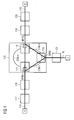
- a resilient packet ring RPR 110 comprising three RPR nodes 111, 112 and 113, each containing an RPR card RPRC.
- a feeder path 114 is connected to RPR node 111
- a feeder path 115 is connected to RPR node 112
- a feeder path 116 is connected to RPR node 113.
- Each feeder path (also referred to as “feeder line”) may traverse one or more network elements (NEs) 117 to 121.
- a network operator may want to create an Ethernet service connecting service endpoints A, B and C by using RPR.
- RPR allows transporting Ethernet frames with low or high priority and supports resiliency with fast recovery times.
- RPR is a transparent service, e.g. STP PBDUs (Spanning Tree Protocol, Protocol Bridge Data Unit) can be transmitted transparently.
- STP PBDUs Spanning Tree Protocol, Protocol Bridge Data Unit
- Fig.1 shows a scenario where an Ethernet Virtual Connection (EVC) has its endpoints at Ethernet ports that are connected via point-to-point Ethernet paths to Ethernet client ports of the RPR 110. These "internal" client ports are connected via an RPR service.
- EMC Ethernet Virtual Connection
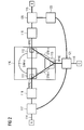
- RPRs can be part of a meshed Ethernet network as shown in Fig.2 .
- the network elements 117 and 121 are connected with each other and the network elements 121 and 120 are connected via a network element 122.
- the resilient packet ring RPR has also to be considered for the route calculation based on a Spanning Tree Protocol (STP, or Multiple Spanning Tree Protocol (MSTP), Rapid Spanning Tree Protocol (RSTP), etc. - various kinds of spanning tree protocols are referred to as "xSTP”), to identify the active route between the end-points of an Ethernet service.
- STP Spanning Tree Protocol
- MSTP Multiple Spanning Tree Protocol
- RSTP Rapid Spanning Tree Protocol
- xSTP various kinds of spanning tree protocols
- Telecommunications Management Network (TMN) system may in particular define an additional, in particular virtual, object for the resilient packet ring RPR,110, also referred to as "RPR Domain”.
- the resilient packet ring RPR 110 can be automatically identified by the TMN system after data of the network elements (NE) 117 to 122 is uploaded. Then, the TMN system creates a new RPR domain object and handles it as a special kind of bridge. Hence, the resilient packet ring RPR 110 in Fig.1 and Fig.2 shows such a particular bridge.
- the RPR domain identified comprises one RPR card per network element 111, 112 and 113, i.e. the RPR domain is associated only with a portion of the NE's resources (and not with the complete network element).
- One network element may have several RPR cards equipped; in such case, this particular network element may be part of several RPR domains.
- the RPR domain object simulates a virtual bridge distributed over several network elements, i.e. network elements 111 to 113 according to the example.
- network elements i.e. network elements 111 to 113 according to the example.
- the WAN ports of the RPR i.e. the ring ports, are not considered.
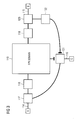
- the RPR domain object resolves logical connections terminating at one of its physical ports. Hence, the RPR domain concept allows the spanning tree to be calculated (and presented to the user) as shown in Fig.3 .
- the network elements 117, 121, 122 and 120 are switches, the resilient packet ring RPR corresponds to the RPR domain 110 and a spanning tree algorithm treats the RPR domain 110 as a single network element.
- the spanning tree algorithm provides the structure according to Fig.3 wherein the connection between the RPR domain 110 and the switch 121 and the connection between the switch 121 and the switch 122 are blocked.
- an unambiguous path connects the endpoints A, B and C of Fig.3 : Path (via) A ⁇ B A ⁇ 117 ⁇ 118 ⁇ 110 ⁇ 119 ⁇ 120 ⁇ B A ⁇ C A ⁇ 117 ⁇ 121 ⁇ C B ⁇ C B ⁇ 120 ⁇ 119 ⁇ 110 ⁇ 118 ⁇ 117 ⁇ 121 ⁇ C
- RPR Domain an additional "RPR Domain” object that in particular simulates a distributed bridge.
- RPR Domain an additional "RPR Domain” object that in particular simulates a distributed bridge.
- Such object is preferably utilized in a TMN system.
Landscapes
- Engineering & Computer Science (AREA)
- Computer Networks & Wireless Communication (AREA)
- Signal Processing (AREA)
- Small-Scale Networks (AREA)
Abstract
A method and a device are provided for utilizing an object in a communication network, the method comprising the following steps of (i) identify a ring structure (110) within the communication network; (ii) assign the ring structure to the object; and (iii) utilize the object comprising said ring structure. Furthermore, a management system and a communication system are provided accordingly.
Description
- The invention relates to a method and to a device for utilizing an object in a communication network, to a management system comprising a functionality of the method and to a communication system comprising the device.
- A Telecommunications Management Network (TMN) is a protocol model defined by ITU-T for managing open systems in a communications network (see, e.g., [1]). TMN provides a framework for enabling interconnectivity and communication across heterogeneous operations system and telecommunication networks. Hence, TMN defines a set of interface points for elements which perform the actual communications processing (such as a call processing switch) to be accessed by elements, such as management workstations, to monitor and control them. The standard interface allows elements from different manufacturers to be incorporated into a network under a single management control. TMN may utilize CMIP (Common Management Information Protocol) for communication between Operations Systems and network elements or Mediation devices when it uses Q3 interface.
- TMN is in particular set forth in ITU-T Recommendation series M.3000, and is based on the OSI management specifications in ITU-T Recommendation series X.700.
- The TMN framework in particular identifies four logical layers of network management:
- Business Management - performs functions related to business aspects, analyzes trends and quality issues, for example, or to provide a basis for billing and other financial reports.
- Service Management - performs functions for the handling of services in the network: definition, administration and charging of services.
- Network Management - performs functions for distribution of network resources: configuration, control and supervision of the network.
- Element Management - contains functions for the handling of individual network elements. This includes alarm management, handling of information, backup, logging, and maintenance of hardware and software.
- A Network Element may further provide so-called agent services, mapping the physical aspects of the equipment into the TMN framework.
- In transport networks it is a requirement that Ethernet services shall be provisioned by the TMN system end-to-end (similar to SDH networks). To be able to support the required end-to-end (e2e) service provisioning, the TMN system must be able to calculate a spanning tree through the network for identification of a route. A route is defined by Virtual LAN (VLAN) assignments to network elements' ports that are traversed by the route.
- A virtual LAN, commonly known as a vLAN or as a VLAN, as described in [2] is a method of creating independent logical networks within a physical network. Several VLANs can coexist within such a network. This helps in reducing the broadcast domain and aids in network administration by separating logical segments of a LAN (like company departments) that should not exchange data using a LAN (they still can exchange data by routing).
- A VLAN may comprise a network of computers that behave as if connected to the same link layer network - even though they may actually be physically connected to different segments of a LAN. Network administrators can configure VLANs through software rather than hardware, which makes them extremely flexible. One of the biggest advantages of VLANs emerges when physically moving a computer to another location: it can stay on the same VLAN without the need for any hardware reconfiguration.
- According to [3], Resilient Packet Ring (RPR), also known as IEEE 802.17, is a standard designed for the optimized transport of data traffic over fiber rings. Its design is to provide the resilience found in SONET/SDH networks (50ms protection) but instead of setting up circuit oriented connections, providing a packet based transmission. This is to increase the reliability and the efficiency of Ethernet and IP services.
- Within the transport network Resilient Packet Rings (RPRs) can be used.
- The problem to be solved is in particular to integrate an RPR structure into an end-to-end provisioning of Ethernet services, in particular for a TMN system.
- This problem is solved according to the features of the independent claims. Further embodiments result from the depending claims.
- In order to overcome this problem, a method for utilizing an object in a communication network is provided comprising the following steps:
- identify a ring structure within the communication network;
- assign the ring structure to the object;
- utilize the object comprising said ring structure.
- Such utilizing of the object may in particular comprise integrating, processing and/or managing of the object. Said utilization may be performed by a management system, in particular by a network management system.
- In an embodiment, the ring structure corresponds to and/or comprises a resilient packet ring (RPR).
- In another embodiment, the resilient packet ring comprises several network elements that are arranged in a ring topology.
- The resilient packet ring may be a ring topology that enables automatic unblocking in case of a link failure. Insofar, the resilient packet ring may be considered a self-organizing structure.
- In a further embodiment, the ring structure is automatically identified by a management system.
- In a next embodiment, the ring structure is automatically identified by the management system after data relating to network elements of the communication network are uploaded to the management system.
- Hence, upon receipt of the data of the network elements, the management system is able to identify the ring structure, in particular a resilient packet ring.
- It is also an embodiment that the management system creates a resilient packet ring domain and utilizes the ring structure as a bridge.
- Pursuant to another embodiment, the ring structure, in particular the resilient packet ring, is treated as a single object by the management system.
- According to an embodiment, a spanning tree algorithm is run throughout the communication network treating the ring structure, in particular the resilient packet ring, as a single object.
- The problem stated supra is also solved by a management system comprising the functionality of the method as described herein.
- According to another embodiment, the management system may be utilized for configuration of the components of the communication network.
- The problem stated supra is also solved by a device comprising a processor unit that is equipped / arranged such that the method as described herein is executable on said processor unit.
- Further, the problem stated above is solved by a communication system comprising the device as described herein.
- Embodiments of the invention are shown and illustrated in the following figures:
- Fig.1
- shows a resilient packet ring RPR in combination with further network elements;
- Fig.2
- shows a meshed network structure based on the structure depicted in
Fig.1 identifying the resilient packet ring as a RPR domain by a TMN system; - Fig.3
- shows how a spanning tree can be set up for the network structure of
Fig.2 , wherein the resilient packet ring RPR is handled as an object, e.g., a bridge. - In
Fig.1 , a resilientpacket ring RPR 110 is shown comprising threeRPR nodes - Furthermore, a
feeder path 114 is connected toRPR node 111, afeeder path 115 is connected toRPR node 112 and afeeder path 116 is connected toRPR node 113. Each feeder path (also referred to as "feeder line") may traverse one or more network elements (NEs) 117 to 121. - A network operator may want to create an Ethernet service connecting service endpoints A, B and C by using RPR. RPR allows transporting Ethernet frames with low or high priority and supports resiliency with fast recovery times.
- For the perspective of the Ethernet protocol, RPR is a transparent service, e.g. STP PBDUs (Spanning Tree Protocol, Protocol Bridge Data Unit) can be transmitted transparently.
-
Fig.1 shows a scenario where an Ethernet Virtual Connection (EVC) has its endpoints at Ethernet ports that are connected via point-to-point Ethernet paths to Ethernet client ports of theRPR 110. These "internal" client ports are connected via an RPR service. - In addition, RPRs can be part of a meshed Ethernet network as shown in
Fig.2 . - In addition to
Fig.1 , thenetwork elements network elements network element 122. - Therefore, the resilient packet ring RPR has also to be considered for the route calculation based on a Spanning Tree Protocol (STP, or Multiple Spanning Tree Protocol (MSTP), Rapid Spanning Tree Protocol (RSTP), etc. - various kinds of spanning tree protocols are referred to as "xSTP"), to identify the active route between the end-points of an Ethernet service.
- The Telecommunications Management Network (TMN) system may in particular define an additional, in particular virtual, object for the resilient packet ring RPR,110, also referred to as "RPR Domain".
- The resilient
packet ring RPR 110 can be automatically identified by the TMN system after data of the network elements (NE) 117 to 122 is uploaded. Then, the TMN system creates a new RPR domain object and handles it as a special kind of bridge. Hence, the resilientpacket ring RPR 110 inFig.1 andFig.2 shows such a particular bridge. - The RPR domain identified comprises one RPR card per
network element - The RPR domain object simulates a virtual bridge distributed over several network elements, i.e.
network elements 111 to 113 according to the example. For the determination of a spanning tree (via, e.g., xSTP), the WAN ports of the RPR, i.e. the ring ports, are not considered. - The RPR domain object resolves logical connections terminating at one of its physical ports. Hence, the RPR domain concept allows the spanning tree to be calculated (and presented to the user) as shown in
Fig.3 . - In
Fig.3 thenetwork elements RPR domain 110 and a spanning tree algorithm treats theRPR domain 110 as a single network element. - In order to avoid any loops within the network elements, the spanning tree algorithm provides the structure according to
Fig.3 wherein the connection between theRPR domain 110 and theswitch 121 and the connection between theswitch 121 and theswitch 122 are blocked. - Hence, an unambiguous path connects the endpoints A, B and C of
Fig.3 :Path (via) A ⇔ B A ⇔ 117 ⇔ 118 ⇔ 110 ⇔ 119 ⇔ 120 ⇔ B A ⇔ C A ⇔ 117 ⇔ 121 ⇔ C B ⇔ C B ⇔ 120 ⇔ 119 ⇔ 110 ⇔ 118 ⇔ 117 ⇔ 121 ⇔ C - The approach presented herein allows to define an additional "RPR Domain" object that in particular simulates a distributed bridge. Such object is preferably utilized in a TMN system.
- Further advantages of this approach are as follows:
- a. It is possible to integrate a resilient packet ring into an end-to-end service provisioning for Ethernet services in a TMN system. A time consuming manual configuration of the service in the network is no longer required as such configuration is supported by the TMN system. This leads to a significant reduction of operating expenditures (OPEX).
- b. The TMN system is able to calculate the spanning tree (according to a spanning tree protocol like xSTP, i.e. MSTP, RSTP, etc.) based route for meshed networks. There is no effort for the user any more required to ensure loop free network topologies. This results in a reduction of operating expenditures (OPEX) as well as to a reduction of capital expenditures (CAPEX).
- c. The TMN system is able to present a distributed RPR as one object in the graphical presentation of the xSTP to the user. In case a failure requires an analysis of the network, this can be performed in a more efficient way thereby leading to a significant reduction of operating expenditures (OPEX).
-
- [1]
- Wikipedia:
http://en.wikipedia.org/wiki/Telecommunications_Manag ement_Network - [2]
- Wikipedia: http://en.wikipedia.org/wiki/Vlan
- [3]
- Wikipedia:
http://en.wikipedia.org/wiki/Resilient_Packet_Ring
Claims (12)
- A method for utilizing an object in a communication network comprising the following steps:- identify a ring structure within the communication network;- assign the ring structure to the object;- utilize the object comprising said ring structure.
- The method according to claim 1, wherein the ring structure corresponds to and/or comprises a resilient packet ring (RPR).
- The method according to any of the preceding claims,
wherein the resilient packet ring comprises several network elements arranged in a ring topology. - The method according to any of the preceding claims,
wherein the ring structure is automatically identified by a management system. - The method according to claim 4, wherein the ring structure is automatically identified by the management system after data relating to network elements of the communication network are uploaded to the management system.
- The method according to claim 5, wherein the management system creates a resilient packet ring domain and utilizes the ring structure as a bridge.
- The method according to any of the preceding claims,
wherein the ring structure is treated as a single object by the management system. - The method according to any of the preceding claims,
wherein a spanning tree algorithm is run throughout the communication network treating the ring structure as a single object. - A management system comprising a functionality according to the method according to any of the preceding claims.
- The management system according to claim 9 utilized for configuration of the components of the communication network.
- A device comprising a processor unit that is arranged such that the method according of any of the claims 1 to 8 is executable on said processor unit.
- Communication system comprising the device according to claim 11.
Priority Applications (1)
| Application Number | Priority Date | Filing Date | Title |
|---|---|---|---|
| EP07014921A EP2020774A1 (en) | 2007-07-30 | 2007-07-30 | Method and device for utilizing an object in a communication network, management system and communication system compris-ing such device |
Applications Claiming Priority (1)
| Application Number | Priority Date | Filing Date | Title |
|---|---|---|---|
| EP07014921A EP2020774A1 (en) | 2007-07-30 | 2007-07-30 | Method and device for utilizing an object in a communication network, management system and communication system compris-ing such device |
Publications (1)
| Publication Number | Publication Date |
|---|---|
| EP2020774A1 true EP2020774A1 (en) | 2009-02-04 |
Family
ID=38754513
Family Applications (1)
| Application Number | Title | Priority Date | Filing Date |
|---|---|---|---|
| EP07014921A Withdrawn EP2020774A1 (en) | 2007-07-30 | 2007-07-30 | Method and device for utilizing an object in a communication network, management system and communication system compris-ing such device |
Country Status (1)
| Country | Link |
|---|---|
| EP (1) | EP2020774A1 (en) |
Cited By (1)
| Publication number | Priority date | Publication date | Assignee | Title |
|---|---|---|---|---|
| EP2688249A1 (en) * | 2012-07-20 | 2014-01-22 | Siemens Aktiengesellschaft | Method for message transmission in a redundant industrial communication network and communication device for a redundant industrial communication network |
Citations (3)
| Publication number | Priority date | Publication date | Assignee | Title |
|---|---|---|---|---|
| US6483812B1 (en) * | 1999-01-06 | 2002-11-19 | International Business Machines Corporation | Token ring network topology discovery and display |
| US20030046390A1 (en) * | 2000-05-05 | 2003-03-06 | Scott Ball | Systems and methods for construction multi-layer topological models of computer networks |
| US7170851B1 (en) * | 2001-07-26 | 2007-01-30 | Ciena Corporation | Systems and methods for automatic topology provisioning for SONET networks |
-
2007
- 2007-07-30 EP EP07014921A patent/EP2020774A1/en not_active Withdrawn
Patent Citations (3)
| Publication number | Priority date | Publication date | Assignee | Title |
|---|---|---|---|---|
| US6483812B1 (en) * | 1999-01-06 | 2002-11-19 | International Business Machines Corporation | Token ring network topology discovery and display |
| US20030046390A1 (en) * | 2000-05-05 | 2003-03-06 | Scott Ball | Systems and methods for construction multi-layer topological models of computer networks |
| US7170851B1 (en) * | 2001-07-26 | 2007-01-30 | Ciena Corporation | Systems and methods for automatic topology provisioning for SONET networks |
Non-Patent Citations (1)
| Title |
|---|
| DAVIK F ET AL: "IEEE 802.17 resilient packet ring tutorial", IEEE COMMUNICATIONS MAGAZINE, IEEE SERVICE CENTER, PISCATAWAY, US, vol. 42, no. 3, March 2004 (2004-03-01), pages 112 - 118, XP011108920, ISSN: 0163-6804 * |
Cited By (3)
| Publication number | Priority date | Publication date | Assignee | Title |
|---|---|---|---|---|
| EP2688249A1 (en) * | 2012-07-20 | 2014-01-22 | Siemens Aktiengesellschaft | Method for message transmission in a redundant industrial communication network and communication device for a redundant industrial communication network |
| CN103581164A (en) * | 2012-07-20 | 2014-02-12 | 西门子公司 | Method for transmitting messages in redundantly operable industrial communication network and communication device for redundantly operable industrial communication network |
| CN103581164B (en) * | 2012-07-20 | 2018-04-13 | 西门子公司 | For can carry out in the industrial communication network of redundant operation the method for message transmission and for can redundant operation industrial communication network communication equipment |
Similar Documents
| Publication | Publication Date | Title |
|---|---|---|
| US10425153B2 (en) | Generalized service protection systems and methods | |
| US10044606B2 (en) | Continuity check systems and methods using hardware native down maintenance end points to emulate hardware up maintenance end points | |
| EP2416533B1 (en) | Virtualized shared protection capacity | |
| US7991872B2 (en) | Vertical integration of network management for ethernet and the optical transport | |
| US10158500B2 (en) | G.8032 prioritized ring switching systems and methods | |
| US20160156540A1 (en) | Systems and methods for dynamic operations, administration, and management | |
| US10091023B2 (en) | Systems and methods to detect and recover from a loop in an Ethernet ring protected network | |
| US9098434B2 (en) | Load balancing systems and methods of MAC learning in multi-slot architectures | |
| US9503338B2 (en) | Systems and methods to detect and propagate UNI operational speed mismatch in ethernet services | |
| US9847914B2 (en) | Method and system for site interconnection over a transport network | |
| US10862706B2 (en) | Detection of node isolation in subtended ethernet ring topologies | |
| US10171358B2 (en) | Port congestion resiliency in a multi-card and multi-switch link aggregation group | |
| US8787396B2 (en) | Centralized control and management planes for different independent switching domains | |
| US20140314087A1 (en) | Architecture for an access network system management protocol control under heterogeneous network management environment | |
| US9742518B2 (en) | Flexible interconnection of scalable systems integrated using optical networks for datacenters | |
| Ryoo et al. | Ethernet ring protection for carrier ethernet networks | |
| CN115086218A (en) | Message processing method, network equipment and controller | |
| CN113037540A (en) | Communication method, device and storage medium | |
| US20140153442A1 (en) | Method, Device, and System for Packet Processing | |
| KR101664436B1 (en) | Transport Software-Defined Network controller of inter-operation between multivendor packet transport networks based on Ethernet and method thereof | |
| US9794146B2 (en) | Methods and systems for a monitoring device to execute commands on an attached switch | |
| EP3817293A1 (en) | Bulk discovery of devices behind a network address translation device | |
| US20140241204A1 (en) | Transit services in ethernet rings with protection | |
| EP3229414B1 (en) | Method and system for transmitting management information | |
| CN114338366A (en) | Data center fault alarm signal positioning method and system |
Legal Events
| Date | Code | Title | Description |
|---|---|---|---|
| PUAI | Public reference made under article 153(3) epc to a published international application that has entered the european phase |
Free format text: ORIGINAL CODE: 0009012 |
|
| AK | Designated contracting states |
Kind code of ref document: A1 Designated state(s): AT BE BG CH CY CZ DE DK EE ES FI FR GB GR HU IE IS IT LI LT LU LV MC MT NL PL PT RO SE SI SK TR |
|
| AX | Request for extension of the european patent |
Extension state: AL BA HR MK RS |
|
| AKX | Designation fees paid | ||
| STAA | Information on the status of an ep patent application or granted ep patent |
Free format text: STATUS: THE APPLICATION IS DEEMED TO BE WITHDRAWN |
|
| 18D | Application deemed to be withdrawn |
Effective date: 20090805 |
|
| REG | Reference to a national code |
Ref country code: DE Ref legal event code: 8566 |