EP2020695A2 - Pouch type battery pack - Google Patents
Pouch type battery pack Download PDFInfo
- Publication number
- EP2020695A2 EP2020695A2 EP20080159700 EP08159700A EP2020695A2 EP 2020695 A2 EP2020695 A2 EP 2020695A2 EP 20080159700 EP20080159700 EP 20080159700 EP 08159700 A EP08159700 A EP 08159700A EP 2020695 A2 EP2020695 A2 EP 2020695A2
- Authority
- EP
- European Patent Office
- Prior art keywords
- pouch
- battery pack
- battery
- heat radiation
- edge
- Prior art date
- Legal status (The legal status is an assumption and is not a legal conclusion. Google has not performed a legal analysis and makes no representation as to the accuracy of the status listed.)
- Withdrawn
Links
Images



Classifications
-
- H—ELECTRICITY
- H01—ELECTRIC ELEMENTS
- H01M—PROCESSES OR MEANS, e.g. BATTERIES, FOR THE DIRECT CONVERSION OF CHEMICAL ENERGY INTO ELECTRICAL ENERGY
- H01M10/00—Secondary cells; Manufacture thereof
- H01M10/04—Construction or manufacture in general
- H01M10/0413—Large-sized flat cells or batteries for motive or stationary systems with plate-like electrodes
-
- H—ELECTRICITY
- H01—ELECTRIC ELEMENTS
- H01M—PROCESSES OR MEANS, e.g. BATTERIES, FOR THE DIRECT CONVERSION OF CHEMICAL ENERGY INTO ELECTRICAL ENERGY
- H01M10/00—Secondary cells; Manufacture thereof
- H01M10/60—Heating or cooling; Temperature control
- H01M10/61—Types of temperature control
- H01M10/613—Cooling or keeping cold
-
- H—ELECTRICITY
- H01—ELECTRIC ELEMENTS
- H01M—PROCESSES OR MEANS, e.g. BATTERIES, FOR THE DIRECT CONVERSION OF CHEMICAL ENERGY INTO ELECTRICAL ENERGY
- H01M10/00—Secondary cells; Manufacture thereof
- H01M10/04—Construction or manufacture in general
- H01M10/0431—Cells with wound or folded electrodes
-
- H—ELECTRICITY
- H01—ELECTRIC ELEMENTS
- H01M—PROCESSES OR MEANS, e.g. BATTERIES, FOR THE DIRECT CONVERSION OF CHEMICAL ENERGY INTO ELECTRICAL ENERGY
- H01M10/00—Secondary cells; Manufacture thereof
- H01M10/60—Heating or cooling; Temperature control
- H01M10/64—Heating or cooling; Temperature control characterised by the shape of the cells
- H01M10/647—Prismatic or flat cells, e.g. pouch cells
-
- H—ELECTRICITY
- H01—ELECTRIC ELEMENTS
- H01M—PROCESSES OR MEANS, e.g. BATTERIES, FOR THE DIRECT CONVERSION OF CHEMICAL ENERGY INTO ELECTRICAL ENERGY
- H01M10/00—Secondary cells; Manufacture thereof
- H01M10/60—Heating or cooling; Temperature control
- H01M10/65—Means for temperature control structurally associated with the cells
- H01M10/655—Solid structures for heat exchange or heat conduction
- H01M10/6554—Rods or plates
- H01M10/6555—Rods or plates arranged between the cells
-
- H—ELECTRICITY
- H01—ELECTRIC ELEMENTS
- H01M—PROCESSES OR MEANS, e.g. BATTERIES, FOR THE DIRECT CONVERSION OF CHEMICAL ENERGY INTO ELECTRICAL ENERGY
- H01M10/00—Secondary cells; Manufacture thereof
- H01M10/60—Heating or cooling; Temperature control
- H01M10/65—Means for temperature control structurally associated with the cells
- H01M10/655—Solid structures for heat exchange or heat conduction
- H01M10/6556—Solid parts with flow channel passages or pipes for heat exchange
- H01M10/6557—Solid parts with flow channel passages or pipes for heat exchange arranged between the cells
-
- H—ELECTRICITY
- H01—ELECTRIC ELEMENTS
- H01M—PROCESSES OR MEANS, e.g. BATTERIES, FOR THE DIRECT CONVERSION OF CHEMICAL ENERGY INTO ELECTRICAL ENERGY
- H01M10/00—Secondary cells; Manufacture thereof
- H01M10/60—Heating or cooling; Temperature control
- H01M10/65—Means for temperature control structurally associated with the cells
- H01M10/656—Means for temperature control structurally associated with the cells characterised by the type of heat-exchange fluid
- H01M10/6561—Gases
-
- H—ELECTRICITY
- H01—ELECTRIC ELEMENTS
- H01M—PROCESSES OR MEANS, e.g. BATTERIES, FOR THE DIRECT CONVERSION OF CHEMICAL ENERGY INTO ELECTRICAL ENERGY
- H01M50/00—Constructional details or processes of manufacture of the non-active parts of electrochemical cells other than fuel cells, e.g. hybrid cells
- H01M50/10—Primary casings; Jackets or wrappings
- H01M50/102—Primary casings; Jackets or wrappings characterised by their shape or physical structure
- H01M50/105—Pouches or flexible bags
-
- Y—GENERAL TAGGING OF NEW TECHNOLOGICAL DEVELOPMENTS; GENERAL TAGGING OF CROSS-SECTIONAL TECHNOLOGIES SPANNING OVER SEVERAL SECTIONS OF THE IPC; TECHNICAL SUBJECTS COVERED BY FORMER USPC CROSS-REFERENCE ART COLLECTIONS [XRACs] AND DIGESTS
- Y02—TECHNOLOGIES OR APPLICATIONS FOR MITIGATION OR ADAPTATION AGAINST CLIMATE CHANGE
- Y02E—REDUCTION OF GREENHOUSE GAS [GHG] EMISSIONS, RELATED TO ENERGY GENERATION, TRANSMISSION OR DISTRIBUTION
- Y02E60/00—Enabling technologies; Technologies with a potential or indirect contribution to GHG emissions mitigation
- Y02E60/10—Energy storage using batteries
-
- Y—GENERAL TAGGING OF NEW TECHNOLOGICAL DEVELOPMENTS; GENERAL TAGGING OF CROSS-SECTIONAL TECHNOLOGIES SPANNING OVER SEVERAL SECTIONS OF THE IPC; TECHNICAL SUBJECTS COVERED BY FORMER USPC CROSS-REFERENCE ART COLLECTIONS [XRACs] AND DIGESTS
- Y02—TECHNOLOGIES OR APPLICATIONS FOR MITIGATION OR ADAPTATION AGAINST CLIMATE CHANGE
- Y02P—CLIMATE CHANGE MITIGATION TECHNOLOGIES IN THE PRODUCTION OR PROCESSING OF GOODS
- Y02P70/00—Climate change mitigation technologies in the production process for final industrial or consumer products
- Y02P70/50—Manufacturing or production processes characterised by the final manufactured product
Definitions
- aspects of the present invention relate to a pouch type battery pack, and more particularly, to a pouch type battery pack suitable for forming a battery pack of a pouch battery.
- a rechargeable battery is classified as a cylindrical, angular or pouch type battery according to an appearance of a case receiving an electrode assembly.
- the pouch type battery includes an electrode assembly and a pouch case surrounding and sealing the electrode assembly.
- the electrode assembly is formed by interposing a separator between cathode and anode plates, and stacking or winding the separator and the plates altogether. Electrode tabs are respectively welded to the cathode and anode plates. The electrode tabs are assembled to project outside the pouch case when the electrode assembly is received in the pouch case.
- the pouch case includes a case body and a case cover.
- the case body has a space that receives the electrode assembly and the case cover is extended from one end of the case body and covers the case body.
- the case body and the case cover are combined with each other by sealing the case cover to a flange formed at a side part of the case body.
- one protection circuit is connected to one pouch battery.
- one protection circuit is included per two or more batteries.
- the pouch batteries are stacked in a vertical direction and fixed by being bonded by a double coated tape interposed therebetween.
- the conventional pouch type battery pack in which the plurality of batteries are stacked and bonded face-to-face with each other, has various problems. For example, when defects of the battery pack not caused from the battery itself are checked, the battery is separated from the pack. In this time, there is a problem that the pouch is damaged by the double coated tape and thus the battery cannot be reused. Particularly, when the battery of the battery pack has a high capacity, the loss in cost becomes large.
- the batteries of the conventional battery pack are stacked while being attached face to face with each other.
- high temperature heat generated from one battery is transferred to adjacent batteries without shielding, thereby increasing the temperature of the battery.
- aspects of the present invention provide a pouch type battery pack that prevents a bare cell from being damaged when a battery is separated from the battery pack in which a plurality of pouch batteries are bonded.
- aspects of the present invention also provide a pouch type battery pack that improves a heat radiation performance under a condition that a plurality of pouch batteries are laminated or stacked.
- a pouch type battery pack including: a first pouch battery; and a second pouch battery adjacent to the first pouch battery, wherein the first and the second pouch batteries are combined by bonding their edges to each other.
- the edges of the two pouch batteries may be bonded to each other by adhesion.
- the pouch battery may further include: a lower case that includes a rectangular bottom surface and an internal space formed by side surfaces formed along four edges of the bottom surface, such that at least three of the side surfaces include flanges projecting outwardly away and in parallel with the bottom surface; and an upper case formed in a shape of rectangular sheet, an edge of the upper case being sealed to the flange of the lower case, wherein combining surfaces may be formed at sealing portions of the lower and upper cases on each of the pouch batteries so as to adhere while contacting each other.
- Each combining surface may be formed by an externally exposed surface of the flange of the lower case where a periphery of the upper case is not sealed.
- the edges of the two pouch batteries may be bonded to each other by an adhesion member.
- Ends of the edges of the two pouch batteries may contact each other at a contact portion, and the adhesion member may be attached to the contact portion so as to bond the two pouch batteries.
- the adhesion member may be interposed between the edges of the two pouch batteries so as to bond the two pouch batteries.
- the two pouch batteries may be stacked while contacting each other face-to-face.
- a heat radiation member may be provided between the stacked pouch batteries.
- the heat radiation member may be formed in a shape of a plate and have an area equal to or less than that of a contact surface with the pouch battery.
- a plurality of radiation holes may be formed so as to pass through the heat radiation member.
- the heat radiation member may include a plurality of radiation grooves formed on a surface that contacts the pouch battery.
- the heat radiation member may include a hollow formed therein so as to have a rectangular parallelepiped shape whose upper and lower ends are open.
- a plurality of barrier plates may be provided in the hollow of the heat radiation member.
- the pouch type battery pack may further include a wrapping sheet that includes a side edge that is bonded to a bonding portion of the two pouch batteries.
- the wrapping sheet may be formed so as to have a length that surrounds the two stacked pouch batteries.
- a pouch type battery pack including: an upper case having a sheet shape; a first electrode assembly provided on a surface of the upper case; and a second electrode assembly provided on the surface of the upper case and adjacent to the first electrode assembly.
- the pouch type battery pack may further include: a lower case that has an internal space formed in a rectangular parallelepiped shape for each of the electrode assemblies, at least three side surfaces of four side surfaces of the internal space including flanges extended outwardly from their upper ends, wherein the upper case is sealed with the flanges of the lower case so as to close up the internal space.
- An upper end of the remaining one side surface of the internal space of the lower case may be formed integrally with the upper case.
- a border portion of the upper case between the electrode assemblies may be folded so as to form two stacked electrode assemblies.
- a heat radiation member may be provided between the two assemblies.
- a pouch type battery pack including: a first pouch battery; a second pouch battery stacked above the first pouch battery; and a heat radiation member to radiate heat produced by the first pouch battery and/or the second pouch battery, the heat radiation member provided between the stacked pouch batteries.
- a heat radiation member to radiate heat produced by the first pouch battery and/or the second pouch battery, the heat radiation member provided between the stacked pouch batteries.
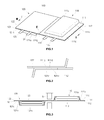
- FIG. 1 is a perspective view illustrating a pouch type battery pack 100 according to an embodiment of the present invention
- FIG. 2 is a magnification view of portion II of FIG. 1
- FIG. 3 is a sectional view taken along the III-III line of FIG. 1 .
- one edge of a first adjacent pouch battery 110 of at least two pouch batteries is bonded to one edge of a second pouch battery 120 by adhesion.
- a construction of the pouch type battery pack 100 includes two pouch batteries 110 and 120, it is understood that aspects of the present invention are not limited thereto. That is, aspects of the present invention may be applied to a pouch type battery pack 100 with any number of pouch batteries.
- Each pouch battery 110 and 120 includes an electrode assembly 113 and 123 in a pouch forming a case.
- Each pouch includes a lower case 111 and 121 and an upper case 112 and 122 to seal the lower case 111 and 121.
- the lower cases 111 and 121 have internal spaces of a roughly rectangular parallelepiped shape where the electrode assemblies 113 and 123 are received.
- the internal spaces are formed by rectangular bottom surfaces 111 a and 121 a and four side surfaces 111 b and 121 b vertically formed along four edges of the bottom surfaces 111a and 121 a.
- Flanges 111c and 121c are provided outwardly at upper ends (i.e., the end closest to the upper cases 112 and 122) of at least three side surfaces 111 b and 121 b of the four side surfaces 111 b and 121 b, and extend parallel to the bottom surfaces 111 a and 121 a.
- the upper cases 112 and 122 are formed in a rectangular sheet shape. Three of the four edges of the upper cases 112 and 122 are sealed with the flanges 111 c and 121 c of the lower cases 111 and 121 so as to close the internal spaces of the lower cases 111 and 121.
- the electrode assemblies 113 and 123 are received inside each lower case 111 and 121, and then the lower cases 111 and 121 are sealed by the upper cases 112 and 122 with a pair of electrode tabs (114, 115, 124 and 125) that project to an outside of the cases 111, 112, 121, and 122, thereby constructing a pouch battery.
- the first pouch battery 110 and the second pouch battery 120 are reversed relative to each other. Furthermore, one edge of the first pouch battery 110 is bonded to one edge of the second pouch battery 120 by adhesion.
- the first and second pouch batteries 110 and 120 with bonded edges are connected to each other in parallel.
- the two pouch batteries 110 and 120 may also be bonded at other edges (except for an edge where an electrode tab 114, 115,124, or 125 protrudes), or only at a left or a right long edge.
- One edge of the first pouch battery 110 is provided to be shorter than a flange 111 c of the lower case 111 that a length of a periphery of the upper case 112 is sealed to.
- the one edge of the first pouch battery 110 that is bonded is the flange 111 c of the lower case 111.
- the flange 111 c of the lower case 111 is not sealed to the upper case 112 and, accordingly, a combining surface 111d exposed to the outside is formed at the flange 111 c.
- one edge of the second pouch battery 120 facing the one edge of the first pouch battery 110 is provided to be shorter than a flange 121 c of the lower case 121 that a length of a periphery of the upper case 122 is sealed to.
- the one edge of the second pouch battery 120 that is bonded is the flange 121 c of the lower case 121.
- the flange 121 c of the lower case 121 is not sealed to the upper case 122 and, accordingly, a combining surface 121d exposed to the outside is formed at the flange 121 c.
- a mark "B" indicates a sealing block.
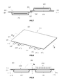
- FIG. 4 is a sectional view illustrating a construction of the pouch battery further including a wrapping sheet according to an embodiment of the present invention.
- a wrapping sheet 130 is further bonded to the bonding portion of the first pouch battery 110 and second pouch battery 120.
- One edge 130a of the wrapping sheet 130 is adhered to the combination of the flange 111 c of the first pouch battery 110 and the flange 121 c of the second pouch battery 120.
- the one edge 130a of the wrapping sheet 130 is adhered to a lower surface of the flange 121 c of the second pouch battery 120.
- the wrapping sheet 130 is provided with a length that can surround the outside of the first pouch battery 110 and second pouch battery 120.
- FIG. 5 is a perspective view illustrating a pouch type battery pack 200 according to another embodiment of the present invention
- FIG. 6 is a sectional view taken along the VI-VI line of FIG. 5 .
- one edge of a first adjacent pouch battery 210 of at least two pouch batteries is bonded to one edge of a second pouch battery 220 by an adhesive member 230.
- the two pouch batteries 210 and 220 illustrated in FIGs. 5 and 6 have the same general shape and structure as the above embodiment described with reference to FIGs. 1 to 3 , and thus, a detailed explanation will be omitted here.
- a separate combining surface is not formed on one edge of a pouch battery 210 and 220, as opposed to the pouch type battery pack 100 described with reference to FIGs. 1 to 3 above.
- Edges 215 and 225 of the two pouch batteries 210 and 220 are respectively contacted to a flange of a lower case 211 and 221 and a periphery of an upper case 212 and 222 with the same length and sealed.
- the lower cases 211 and 221 provide a space for electrode assemblies 213 and 223 of the pouch batteries 210 and 220.
- the two pouch batteries 210 and 220 are arranged so as to allow the edge 215 of the first pouch battery 210 and the edge 225 of the second pouch battery 220 to contact each other. Specifically, an upper surface of one edge 215 or 225 and a lower surface of the other edge 225 or 215 are respectively attached by the adhesive member 230 (such as a bonding tape). Thus, the edge 215 of the first pouch battery 210 and the edge 225 of the second pouch battery 220 are bonded to each other and the two pouch batteries 210 and 220 are connected in parallel.
- the adhesive member 230 such as a bonding tape
- FIG. 7 is a sectional view illustrating a modification example of the pouch type battery pack according to another embodiment of the present invention.
- two pouch batteries 210 and 220 are arranged such that the edge 215 of the first pouch battery 210 and the edge 225 of the second pouch battery 220 overlap.
- An adhesive member 240 (such as a double coated tape) is interposed between the edge 215 of the first pouch battery 210 and the edge 225 of the second pouch battery 220. Specifically, the two edges 215 and 225 are bonded to each other by the adhesive member 240 so as to connect the two pouch batteries 210 and 220 with each other in parallel.
- FIG. 8 is a perspective view illustrating a pouch type battery pack 300 according to still another embodiment of the present invention and FIG. 9 is a sectional view taken along the IX-IX line of FIG. 8 .
- the pouch type battery pack 300 is constructed by forming one or more internal spaces 311 a and 311 b that receive at least two electrode assemblies 313 and 313' in one pouch battery 310.
- the pouch type battery pack 300 has the same construction as a pouch type battery pack in which at least two pouch batteries are integrally formed.
- the internal spaces 311 a and 311 b are formed in a lower case 311 of the pouch battery 310.
- the internal spaces 311a and 311 b have a volume corresponding to the size of the respective electrode assemblies 313 and 313'.
- the internal spaces 311 a and 311b are formed to correspond to the shape of the respective electrode assemblies 313 and 313' (for example, in roughly rectangular parallelepiped shapes).
- outwardly extended flanges 311 c and 311 d are provided at upper ends of three side surfaces of the internal spaces 311 a and 311 b.
- An upper case 312 is formed in a sheet shape.
- a peripheral part of the upper case 312 is sealed to the flanges 311 c and 311 d of the lower case 311 so as to close up the internal spaces 311 a and 311 b.
- An upper end of the remaining one side surface (i.e., the side surface from which no flange protrudes) of the each internal space 311 a and 311 b is formed integrally with the upper case 312.
- Electrode tabs (314, 315, 314' and 315') of the electrode assemblies 313 and 313' are respectively projected to an outside of the lower case 311.
- a virtual line Z-Z' indicates a state that first and second pouch battery regions 310A and 310B are formed in a pouch battery.
- a structure of a pouch type battery pack 300 including two stacked pouch batteries is formed by folding the second pouch battery region 310B in a direction of an arrow mark to the first pouch battery region 310A about the virtual line Z-Z'.
- FIG. 10 is a perspective view illustrating a state that two pouch batteries are stacked, their edges being bonded to each other by adhesion, according to an embodiment of the present invention.
- the two pouch batteries 110 and 120 are stacked in a vertical direction by folding a second pouch battery region 120 above a first pouch battery region 110. Furthermore, edges of the first and second pouch batteries 110 and 120 are bonded to each other by adhesion so as to be connected with each other in parallel.
- a core pack is constructed by connecting electrode tabs 114 and 115 of the first pouch battery 110 and electrode tabs 124 and 125 of the second pouch battery 120 with a protection circuit 140. Accordingly, assembling of the battery pack 100 is completed by assembling other accessories in a state where the two pouch batteries 110 and 120 are not separated from each other.
- FIG. 11 is a sectional view illustrating a heat radiation structure for improving a heat radiation performance of two pouch batteries 110 and 120 stacked according to an embodiment of the present invention.
- a pouch type battery pack 100 includes a first pouch battery 110, a second pouch battery 120 stacked on the first pouch battery 110, and a heat radiation member 150 interposed between the two pouch batteries 110 and 120.
- the heat radiation member 150 may have a plate shape. Furthermore, the heat radiation member 150 may have an area equal to or less than that of a contact surface between the two pouch batteries 110 and 120. When the size of the heat radiation member 150 is too large, the heat radiation member 150 may project from the stacked pouch batteries 110 and 120, thereby worsening an assembly of the pouch type battery pack 100. A plurality of heat radiation holes 150a are provided to pass through the heat radiation member 150.
- the two pouch batteries are spaced apart by the thickness of the heat radiation member 150.
- the two pouch batteries 110 and 120 are shielded by the heat radiation member 150. Thus, heat generated from each pouch battery 110 and 120 does not affect a respective adjacent battery 120 and 110.
- Low temperature air flows through a heat radiation hole 150a formed in the heat radiation member 150.
- the low temperature air is heat-exchanged with high temperature air generated from the first and second pouch batteries 110 and 120, thereby decreasing temperatures of the two pouch batteries 110 and 120.
- the heat radiation performance of the pouch battery 100 is improved.
- FIG. 12 is a sectional view illustrating a heat radiation structure for improving a heat radiation performance of the two pouch batteries 210 and 220 stacked according to the another embodiment of the present invention.
- a pouch type battery pack 200 includes a first pouch battery 210, a second pouch battery 220 stacked on the first pouch battery 210, and a heat radiation member 250 interposed between the two pouch batteries 210 and 220.
- the heat radiation member 250 may have a plate shape. Furthermore, the heat radiation member 250 may have an area equal to or less than that of a contact surface between the two pouch batteries 210 and 220. A plurality of heat radiation holes 250a are provided to pass through the heat radiation member 250.
- the heat radiation member 250 has substantially the same shape, structure, operation, and effect as the heat radiation member 150 described with reference to FIG. 11 , and a detailed explanation will be omitted.
- the pouch battery pack 200 of FIG. 12 further includes a wrapping sheet 130 (as described with reference to FIG. 4 ). Furthermore, it is understood that the heat radiation member 150 and 250 applicable to the pouch type battery pack 100 and 200 is not limited those as described above.
- a heat radiation member 350 in a heat radiation member 350, semi-circular heat radiation grooves 352 and 353 are respectively formed on upper and lower surfaces of a heat radiation plate 351.
- the heat radiation grooves 352 and 353 may be formed on only one surface of the heat radiation plate 351, or on both the upper and lower surfaces of the heat radiation plate 351.
- the heat radiation grooves 352 and 353 may be formed in only a predetermined direction.
- sectional surfaces of the heat radiation grooves 352 and 353 may be formed in triangular, rectangular or polygonal shapes.
- the heat radiation grooves 352 and 353 are formed on the upper and/or lower surface where the heat radiation member 350 contacts the two pouch batteries. Thus, air passing through heat radiation grooves 352 and 353 is heat-exchanged with heat generated from the two pouch batteries, thereby decreasing the temperatures of the two pouch batteries.
- a heat radiation member 450 according to a different embodiment than that illustrated in FIG. 13A includes a hollow 452 so as to be formed as a rectangular parallelepiped heat radiation plate 451 whose upper and lower ends are opened. External air of low temperature fills through the hollow 452, thereby decreasing the temperature of the two pouch batteries that contact the upper and lower surfaces face-to-face.
- a heat radiation member 550 according to a different embodiment than those illustrated in FIGs. 13A and 13B includes a hollow 552 so as to be formed as a rectangular parallelepiped heat radiation plate 551 whose upper and lower ends are opened.
- a plurality of barrier plates 553 are included in the hollow 552 so as to divide an inner space of the hollow 552.
- the barrier plates 553 guide a flow of external air passing through the hollow 552, thereby allowing the air to be smoothly flowed.
- the temperature of the two pouch batteries that contact the upper and lower surfaces of the heat radiation plate 551 face-to-face is decreased.
- heat radiation member according to aspects of the present invention is not limited to those as described above, and can be modified variously. Furthermore, such a heat radiation member can be applied to the various battery pack embodiments, in particular the stacked battery pack obtained from the embodiment of Figure 9 .
- the pouch type battery pack has the following advantages.
Landscapes
- Chemical & Material Sciences (AREA)
- Chemical Kinetics & Catalysis (AREA)
- Electrochemistry (AREA)
- General Chemical & Material Sciences (AREA)
- Engineering & Computer Science (AREA)
- Manufacturing & Machinery (AREA)
- Secondary Cells (AREA)
- Battery Mounting, Suspending (AREA)
- Primary Cells (AREA)
Abstract
Description
- Aspects of the present invention relate to a pouch type battery pack, and more particularly, to a pouch type battery pack suitable for forming a battery pack of a pouch battery.
- Generally, a rechargeable battery is classified as a cylindrical, angular or pouch type battery according to an appearance of a case receiving an electrode assembly. Specifically, the pouch type battery includes an electrode assembly and a pouch case surrounding and sealing the electrode assembly. The electrode assembly is formed by interposing a separator between cathode and anode plates, and stacking or winding the separator and the plates altogether. Electrode tabs are respectively welded to the cathode and anode plates. The electrode tabs are assembled to project outside the pouch case when the electrode assembly is received in the pouch case.
- The pouch case includes a case body and a case cover. The case body has a space that receives the electrode assembly and the case cover is extended from one end of the case body and covers the case body. The case body and the case cover are combined with each other by sealing the case cover to a flange formed at a side part of the case body.
- Generally, when a battery pack is formed by a single pouch type rechargeable battery, one protection circuit is connected to one pouch battery. On the other hand, in the case of a notebook computer and the like that require a high capacity battery in addition to the single pouch type battery, one protection circuit is included per two or more batteries. When two or more batteries are included per one protection circuit, the pouch batteries are stacked in a vertical direction and fixed by being bonded by a double coated tape interposed therebetween.
- However, the conventional pouch type battery pack, in which the plurality of batteries are stacked and bonded face-to-face with each other, has various problems. For example, when defects of the battery pack not caused from the battery itself are checked, the battery is separated from the pack. In this time, there is a problem that the pouch is damaged by the double coated tape and thus the battery cannot be reused. Particularly, when the battery of the battery pack has a high capacity, the loss in cost becomes large.
- In addition, the batteries of the conventional battery pack are stacked while being attached face to face with each other. Thus, high temperature heat generated from one battery is transferred to adjacent batteries without shielding, thereby increasing the temperature of the battery. Similarly, there is a problem that it is difficult to perform heat radiation because there is no gap between the batteries.
- Aspects of the present invention provide a pouch type battery pack that prevents a bare cell from being damaged when a battery is separated from the battery pack in which a plurality of pouch batteries are bonded.
- Aspects of the present invention also provide a pouch type battery pack that improves a heat radiation performance under a condition that a plurality of pouch batteries are laminated or stacked.
- According to an aspect of the present invention, there is provided a pouch type battery pack, including: a first pouch battery; and a second pouch battery adjacent to the first pouch battery, wherein the first and the second pouch batteries are combined by bonding their edges to each other.
- The edges of the two pouch batteries may be bonded to each other by adhesion.
- The pouch battery may further include: a lower case that includes a rectangular bottom surface and an internal space formed by side surfaces formed along four edges of the bottom surface, such that at least three of the side surfaces include flanges projecting outwardly away and in parallel with the bottom surface; and an upper case formed in a shape of rectangular sheet, an edge of the upper case being sealed to the flange of the lower case, wherein combining surfaces may be formed at sealing portions of the lower and upper cases on each of the pouch batteries so as to adhere while contacting each other.
- Each combining surface may be formed by an externally exposed surface of the flange of the lower case where a periphery of the upper case is not sealed.
- The edges of the two pouch batteries may be bonded to each other by an adhesion member.
- Ends of the edges of the two pouch batteries may contact each other at a contact portion, and the adhesion member may be attached to the contact portion so as to bond the two pouch batteries.
- The adhesion member may be interposed between the edges of the two pouch batteries so as to bond the two pouch batteries.
- The two pouch batteries may be stacked while contacting each other face-to-face.
- A heat radiation member may be provided between the stacked pouch batteries.
- The heat radiation member may be formed in a shape of a plate and have an area equal to or less than that of a contact surface with the pouch battery.
- A plurality of radiation holes may be formed so as to pass through the heat radiation member.
- The heat radiation member may include a plurality of radiation grooves formed on a surface that contacts the pouch battery.
- The heat radiation member may include a hollow formed therein so as to have a rectangular parallelepiped shape whose upper and lower ends are open.
- A plurality of barrier plates may be provided in the hollow of the heat radiation member.
- The pouch type battery pack may further include a wrapping sheet that includes a side edge that is bonded to a bonding portion of the two pouch batteries.
- The wrapping sheet may be formed so as to have a length that surrounds the two stacked pouch batteries.
- According to another aspect of the present invention, there is provided a pouch type battery pack, including: an upper case having a sheet shape; a first electrode assembly provided on a surface of the upper case; and a second electrode assembly provided on the surface of the upper case and adjacent to the first electrode assembly.
- The pouch type battery pack may further include: a lower case that has an internal space formed in a rectangular parallelepiped shape for each of the electrode assemblies, at least three side surfaces of four side surfaces of the internal space including flanges extended outwardly from their upper ends, wherein the upper case is sealed with the flanges of the lower case so as to close up the internal space.
- An upper end of the remaining one side surface of the internal space of the lower case may be formed integrally with the upper case.
- A border portion of the upper case between the electrode assemblies may be folded so as to form two stacked electrode assemblies. In this case also a heat radiation member may be provided between the two assemblies.
- According to yet another aspect of the present invention, there is provided a pouch type battery pack, including: a first pouch battery; a second pouch battery stacked above the first pouch battery; and a heat radiation member to radiate heat produced by the first pouch battery and/or the second pouch battery, the heat radiation member provided between the stacked pouch batteries. Optional features set forth above may also apply to this aspect.
- Additional aspects and/or advantages of the invention will be set forth in part in the description which follows.
- These and/or other aspects and advantages of the invention will become apparent and more readily appreciated from the following description of the embodiments, taken in conjunction with the accompanying drawings of which:
-
FIG. 1 is a perspective view illustrating a pouch type battery pack according to an embodiment of the present invention; -
FIG. 2 is a magnification view of portion II ofFIG. 1 ; -
FIG. 3 is a sectional view taken along the III-III line ofFIG. 1 ; -
FIG. 4 is a sectional view illustrating a construction of the pouch type battery pack further including a wrapping sheet according to an embodiment of the present invention; -
FIG. 5 is a perspective view illustrating a pouch type battery pack according to another embodiment of the present invention; -
FIG. 6 is a sectional view taken along the VI-VI line ofFIG. 5 ; -
FIG. 7 is a sectional view illustrating a modification example of the pouch type battery pack according to another embodiment of the present invention; -
FIG. 8 is a perspective view illustrating a pouch type battery pack according to still another embodiment of the present invention; -
FIG. 9 is a sectional view taken along the IX-IX line ofFIG. 8 ; -
FIG. 10 is a perspective view illustrating a state that two pouch batteries are stacked according to an embodiment of the present invention; -
FIG. 11 is a sectional view illustrating a heat radiation structure of the pouch type battery pack according to an embodiment of the present invention; -
FIG. 12 is a sectional view illustrating a heat radiation structure of the pouch type battery pack according to another embodiment of the present invention; and -
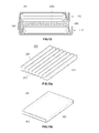
FIGs. 13A to 13C are perspective views illustrating the heat radiation structure according to various embodiments of the present invention. - Reference will now be made in detail to the present embodiments of the present invention, examples of which are illustrated in the accompanying drawings, wherein like reference numerals refer to the like elements throughout. The embodiments are described below in order to explain the present invention by referring to the figures.
-
FIG. 1 is a perspective view illustrating a pouchtype battery pack 100 according to an embodiment of the present invention,FIG. 2 is a magnification view of portion II ofFIG. 1, and FIG. 3 is a sectional view taken along the III-III line ofFIG. 1 . - Referring to
FIGs. 1 to 3 , in the pouchtype battery pack 100, one edge of a firstadjacent pouch battery 110 of at least two pouch batteries is bonded to one edge of asecond pouch battery 120 by adhesion. While with reference toFIGs. 1 to 3 , a construction of the pouchtype battery pack 100 includes twopouch batteries type battery pack 100 with any number of pouch batteries. - Each
pouch battery electrode assembly lower case upper case lower case - The
lower cases electrode assemblies side surfaces bottom surfaces Flanges upper cases 112 and 122) of at least threeside surfaces side surfaces upper cases upper cases flanges lower cases lower cases - Like this, the
electrode assemblies lower case lower cases upper cases cases - As illustrated in
FIGs. 1 to 3 , thefirst pouch battery 110 and thesecond pouch battery 120 are reversed relative to each other. Furthermore, one edge of thefirst pouch battery 110 is bonded to one edge of thesecond pouch battery 120 by adhesion. The first andsecond pouch batteries pouch batteries electrode tab 114, 115,124, or 125 protrudes), or only at a left or a right long edge. - The structure that is formed by bonding edges of the first and
second pouch batteries first pouch battery 110 is provided to be shorter than aflange 111 c of thelower case 111 that a length of a periphery of theupper case 112 is sealed to. Thus, the one edge of thefirst pouch battery 110 that is bonded is theflange 111 c of thelower case 111. Theflange 111 c of thelower case 111 is not sealed to theupper case 112 and, accordingly, a combiningsurface 111d exposed to the outside is formed at theflange 111 c. - Likewise, one edge of the
second pouch battery 120 facing the one edge of thefirst pouch battery 110 is provided to be shorter than aflange 121 c of thelower case 121 that a length of a periphery of theupper case 122 is sealed to. Thus, the one edge of thesecond pouch battery 120 that is bonded is theflange 121 c of thelower case 121. Theflange 121 c of thelower case 121 is not sealed to theupper case 122 and, accordingly, a combiningsurface 121d exposed to the outside is formed at theflange 121 c. - Thus, the combining
surface 111d exposed from the one edge of thefirst pouch battery 110 and the combiningsurface 121d exposed from the one edge of thesecond pouch battery 120 contact each other. As a result, theflange 111 c of thelower case 111 of thefirst pouch battery 110 and theflange 121 c of thelower case 121 of thesecond pouch battery 120 are adhered to each other. InFIG. 3 , a mark "B" indicates a sealing block. -
FIG. 4 is a sectional view illustrating a construction of the pouch battery further including a wrapping sheet according to an embodiment of the present invention. Referring toFIG. 4 , awrapping sheet 130 is further bonded to the bonding portion of thefirst pouch battery 110 andsecond pouch battery 120. Oneedge 130a of thewrapping sheet 130 is adhered to the combination of theflange 111 c of thefirst pouch battery 110 and theflange 121 c of thesecond pouch battery 120. Specifically, the oneedge 130a of thewrapping sheet 130 is adhered to a lower surface of theflange 121 c of thesecond pouch battery 120. Furthermore, thewrapping sheet 130 is provided with a length that can surround the outside of thefirst pouch battery 110 andsecond pouch battery 120. -
FIG. 5 is a perspective view illustrating a pouchtype battery pack 200 according to another embodiment of the present invention, andFIG. 6 is a sectional view taken along the VI-VI line ofFIG. 5 . Referring toFIGs. 5 and 6 , in the pouchtype battery pack 200, one edge of a firstadjacent pouch battery 210 of at least two pouch batteries is bonded to one edge of asecond pouch battery 220 by anadhesive member 230. - The two
pouch batteries FIGs. 5 and 6 have the same general shape and structure as the above embodiment described with reference toFIGs. 1 to 3 , and thus, a detailed explanation will be omitted here. In the pouchtype battery pack 200 described with reference toFIGs. 5 and 6 however, a separate combining surface is not formed on one edge of apouch battery type battery pack 100 described with reference toFIGs. 1 to 3 above.Edges pouch batteries lower case upper case lower cases electrode assemblies pouch batteries - The two
pouch batteries edge 215 of thefirst pouch battery 210 and theedge 225 of thesecond pouch battery 220 to contact each other. Specifically, an upper surface of oneedge other edge edge 215 of thefirst pouch battery 210 and theedge 225 of thesecond pouch battery 220 are bonded to each other and the twopouch batteries -
FIG. 7 is a sectional view illustrating a modification example of the pouch type battery pack according to another embodiment of the present invention. Referring toFIG. 7 , in the modification example, twopouch batteries edge 215 of thefirst pouch battery 210 and theedge 225 of thesecond pouch battery 220 overlap. - An adhesive member 240 (such as a double coated tape) is interposed between the
edge 215 of thefirst pouch battery 210 and theedge 225 of thesecond pouch battery 220. Specifically, the twoedges adhesive member 240 so as to connect the twopouch batteries -
FIG. 8 is a perspective view illustrating a pouchtype battery pack 300 according to still another embodiment of the present invention andFIG. 9 is a sectional view taken along the IX-IX line ofFIG. 8 . Referring toFIGs. 8 and 9 , the pouchtype battery pack 300 is constructed by forming one or moreinternal spaces electrode assemblies 313 and 313' in onepouch battery 310. Thus, it has the same construction as a pouch type battery pack in which at least two pouch batteries are integrally formed. - In the pouch
type battery pack 300, twointernal spaces lower case 311 of thepouch battery 310. Theinternal spaces respective electrode assemblies 313 and 313'. Furthermore, theinternal spaces respective electrode assemblies 313 and 313' (for example, in roughly rectangular parallelepiped shapes). In addition, outwardlyextended flanges internal spaces upper case 312 is formed in a sheet shape. A peripheral part of theupper case 312 is sealed to theflanges lower case 311 so as to close up theinternal spaces internal space upper case 312. - Each
electrode assembly 313 and 313' is received in the eachinternal space electrode assemblies 313 and 313' are respectively projected to an outside of thelower case 311. - Referring to
FIG. 9 , a virtual line Z-Z' indicates a state that first and secondpouch battery regions type battery pack 300 including two stacked pouch batteries is formed by folding the secondpouch battery region 310B in a direction of an arrow mark to the firstpouch battery region 310A about the virtual line Z-Z'. -
FIG. 10 is a perspective view illustrating a state that two pouch batteries are stacked, their edges being bonded to each other by adhesion, according to an embodiment of the present invention. The twopouch batteries pouch battery region 120 above a firstpouch battery region 110. Furthermore, edges of the first andsecond pouch batteries electrode tabs first pouch battery 110 andelectrode tabs second pouch battery 120 with aprotection circuit 140. Accordingly, assembling of thebattery pack 100 is completed by assembling other accessories in a state where the twopouch batteries - A heat radiation structure applied to the pouch type battery pack will now be explained.
FIG. 11 is a sectional view illustrating a heat radiation structure for improving a heat radiation performance of twopouch batteries FIG. 11 , a pouchtype battery pack 100 includes afirst pouch battery 110, asecond pouch battery 120 stacked on thefirst pouch battery 110, and aheat radiation member 150 interposed between the twopouch batteries - The
heat radiation member 150 may have a plate shape. Furthermore, theheat radiation member 150 may have an area equal to or less than that of a contact surface between the twopouch batteries heat radiation member 150 is too large, theheat radiation member 150 may project from the stackedpouch batteries type battery pack 100. A plurality ofheat radiation holes 150a are provided to pass through theheat radiation member 150. - When the
heat radiation member 150 is provided between the first andsecond pouch batteries heat radiation member 150. The twopouch batteries heat radiation member 150. Thus, heat generated from eachpouch battery adjacent battery - Low temperature air flows through a
heat radiation hole 150a formed in theheat radiation member 150. The low temperature air is heat-exchanged with high temperature air generated from the first andsecond pouch batteries pouch batteries pouch battery 100 is improved. -
FIG. 12 is a sectional view illustrating a heat radiation structure for improving a heat radiation performance of the twopouch batteries FIG. 12 , a pouchtype battery pack 200 includes afirst pouch battery 210, asecond pouch battery 220 stacked on thefirst pouch battery 210, and aheat radiation member 250 interposed between the twopouch batteries - The
heat radiation member 250 may have a plate shape. Furthermore, theheat radiation member 250 may have an area equal to or less than that of a contact surface between the twopouch batteries heat radiation holes 250a are provided to pass through theheat radiation member 250. - The
heat radiation member 250 has substantially the same shape, structure, operation, and effect as theheat radiation member 150 described with reference toFIG. 11 , and a detailed explanation will be omitted. Thepouch battery pack 200 ofFIG. 12 further includes a wrapping sheet 130 (as described with reference toFIG. 4 ). Furthermore, it is understood that theheat radiation member type battery pack - Next, other various embodiments of the
heat radiation member FIGs. 13A to 13C . Referring toFIG. 13A , in aheat radiation member 350, semi-circularheat radiation grooves heat radiation plate 351. Theheat radiation grooves heat radiation plate 351, or on both the upper and lower surfaces of theheat radiation plate 351. Furthermore, theheat radiation grooves heat radiation grooves - The
heat radiation grooves heat radiation member 350 contacts the two pouch batteries. Thus, air passing throughheat radiation grooves - Referring to
FIG. 13B , aheat radiation member 450 according to a different embodiment than that illustrated inFIG. 13A includes a hollow 452 so as to be formed as a rectangular parallelepipedheat radiation plate 451 whose upper and lower ends are opened. External air of low temperature fills through the hollow 452, thereby decreasing the temperature of the two pouch batteries that contact the upper and lower surfaces face-to-face. - Referring to
FIG. 13C , aheat radiation member 550 according to a different embodiment than those illustrated inFIGs. 13A and 13B includes a hollow 552 so as to be formed as a rectangular parallelepipedheat radiation plate 551 whose upper and lower ends are opened. A plurality ofbarrier plates 553 are included in the hollow 552 so as to divide an inner space of the hollow 552. Thebarrier plates 553 guide a flow of external air passing through the hollow 552, thereby allowing the air to be smoothly flowed. Thus, the temperature of the two pouch batteries that contact the upper and lower surfaces of theheat radiation plate 551 face-to-face is decreased. - It is understood that the heat radiation member according to aspects of the present invention is not limited to those as described above, and can be modified variously. Furthermore, such a heat radiation member can be applied to the various battery pack embodiments, in particular the stacked battery pack obtained from the embodiment of
Figure 9 . - As described above, the pouch type battery pack according to aspects of the present invention has the following advantages. First, the bare cell the pouch type battery pack is not damaged and can be reused by separating only one bonded edge when the pouch battery is separated from the battery pack because edges of at least two adjacent pouch batteries are connected with each other by adhesion. Second, the pouch type battery pack can increase the heat radiation performance when the pouch batteries are stacked. Third, the pouch type battery pack improves reliability of the product in a large capacity battery pack.
Claims (22)
- Pouch type battery pack (100; 200), comprising:a first pouch battery (110; 210); anda second pouch battery (120; 220) adjacent to the first pouch battery (110; 210),wherein the first and the second pouch batteries (110, 120; 210, 220) are combined by bonding an edge of the first pouch battery and an edge of the second pouch battery to each other.
- Pouch type battery pack according to claim 1, wherein the edge of the first pouch battery (110) and the edge of the second pouch battery (120) are bonded to each other by adhesion.
- Pouch type battery pack according to claim 2, wherein each pouch battery comprises:a lower case (111; 121) comprising a rectangular bottom surface (111 a; 121 a), four side surfaces (111b; 121b) formed along four edges of the bottom surface (111 a; 121 a), and an internal space formed by the side surfaces, such that at least three of the side surfaces (111b; 121 b) include flanges (111 c; 121 c) that project away from the inside surface in parallel with the bottom surface (111 a; 121 a); andan upper case (112; 122) formed in a shape of rectangular sheet so as to be sealed to the flanges (111 c; 121 c) of the lower case (111; 121),wherein a combining surface (111 d; 121 d) is formed at a sealing portion of the lower case (111; 121) and the upper case (112; 122) so that the combining surface (111 d) of the first pouch battery (110) and the combining surface (121 d) of the second pouch battery (120) are adhered together when in contact with each other.
- Pouch type battery pack according to claim 3, wherein the combining surface (111 d; 121 d) is a surface of a flange (111 c; 121 c) of the lower case (111; 121) that is externally exposed and on which a periphery of the upper case (112; 122) is not sealed.
- Pouch type battery pack according to claim 1, further comprising an adhesion member (230; 240) to bond the edge (215) of the first pouch battery (210) and the edge (225) of the second pouch battery (220) to each other.
- Pouch type battery pack according to claim 5, wherein the adhesion member is attached to a contact portion where an end of the edge of the first pouch battery and an end of the edge of the second pouch battery contact each other.
- Pouch type battery pack according to claim 5, wherein the adhesion member (240) is interposed between the edge (215) of the first pouch battery (210) and the edge (225) of the second pouch battery (220).
- Pouch type battery pack according to claim 1, wherein the first pouch battery (110; 210) is stacked face-to-face with the second pouch battery (120; 220).
- Pouch type battery pack according to claim 8, further comprising a heat radiation member (150) to radiate heat produced by the first pouch battery (110) and/or the second pouch battery (120), the heat radiation member being provided between the stacked pouch batteries.
- Pouch type battery pack according to claim 9, wherein the heat radiation member (150) has a surface area of a top surface equal to or less than a surface area of a surface of the first pouch battery (110) in contact with the top surface of the heat radiation member (150), and has a surface area of a bottom surface equal to or less than a surface area of a surface of the second pouch battery (120) in contact with the bottom surface of the heat radiation member (150).
- Pouch type battery pack according to claim 10, wherein the heat radiation member (150) comprises a plurality of radiation holes (150a) formed to pass through the heat radiation member from the top surface to the bottom surface.
- Pouch type battery pack according to claim 10, wherein the heat radiation member (350) comprises a plurality of radiation grooves (352, 353 formed on the top surface and/or the bottom surface.
- Pouch type battery pack according to claim 10, wherein the heat radiation member (450; 550) comprises a hollow (452; 552) formed between the top surface and the bottom surface.
- Pouch type battery pack according to claim 13, wherein a plurality of barrier plates (553) are provided in the hollow (552) of the heat radiation member (550) to guide a flow of external air passing through the hollow.
- Pouch type battery pack according to claim 1, further comprising a wrapping sheet (130) having a side edge (130a) that is bonded to the edge of the first pouch battery and/or the edge (121 c) of the second pouch battery (120).
- Pouch type battery pack according to claim 15, wherein the wrapping sheet (130) surrounds the first and the second pouch batteries (110, 120) when the first and the second pouch batteries are stacked.
- Pouch type battery pack according to claim 1, wherein the first pouch battery and the second pouch battery are connected only at the edge of the first pouch battery and the edge of the second pouch battery.
- Pouch type battery pack (310), comprising:an upper case (312) having a sheet shape;a first electrode assembly (313) provided on a surface of the upper case (312); anda second electrode assembly (313') provided on the surface of the upper case (312) and adjacent to the first electrode assembly (313).
- Pouch type battery pack according to claim 18, further comprising:a lower case (311) comprising four side surfaces and having a shape to form a first internal space (311a) in a rectangular parallelepiped shape to receive the first electrode assembly (313) and a second internal (311b) space in the rectangular parallelepiped shape to receive the second electrode assembly (313'),wherein at least three of the side surfaces include flanges (311 c; 311 d) projecting away from the internal spaces (311 a; 311 b), and the upper case (312) is sealed with the flanges (311c; 311d) of the lower case (311) so as to close up the first and second internal spaces (311a, 311b).
- Pouch type battery pack according to claim 19, wherein a side surface of the lower case (311) that does not include a flange is formed integrally with the upper case (312).
- Pouch type battery pack according to any of claims 18 to 20, wherein a portion of the upper case (312) between the first electrode assembly (313) and the second electrode assembly (313') is adapted to be folded so as to stack the first electrode assembly (313) and the second electrode assembly (313').
- Pouch type battery pack according to claim 21, further comprising a heat radiation member to radiate heat produced by the first electrode assembly and/or the second electrode assembly, the heat radiation member being provided between the stacked electrode assemblies.
Applications Claiming Priority (1)
| Application Number | Priority Date | Filing Date | Title |
|---|---|---|---|
| KR1020070072185A KR100870355B1 (en) | 2007-07-19 | 2007-07-19 | Pouch Type Battery Pack |
Publications (2)
| Publication Number | Publication Date |
|---|---|
| EP2020695A2 true EP2020695A2 (en) | 2009-02-04 |
| EP2020695A3 EP2020695A3 (en) | 2009-06-24 |
Family
ID=39831876
Family Applications (1)
| Application Number | Title | Priority Date | Filing Date |
|---|---|---|---|
| EP20080159700 Withdrawn EP2020695A3 (en) | 2007-07-19 | 2008-07-04 | Pouch type battery pack |
Country Status (5)
| Country | Link |
|---|---|
| US (1) | US8173293B2 (en) |
| EP (1) | EP2020695A3 (en) |
| JP (1) | JP5203743B2 (en) |
| KR (1) | KR100870355B1 (en) |
| CN (1) | CN101350400B (en) |
Cited By (4)
| Publication number | Priority date | Publication date | Assignee | Title |
|---|---|---|---|---|
| EP2219245A1 (en) * | 2009-02-17 | 2010-08-18 | Samsung SDI Co., Ltd. | Secondary Battery with Protection Circuit Module |
| EP2299511A1 (en) * | 2009-08-18 | 2011-03-23 | Samsung SDI Co., Ltd. | Rechargeable battery and battery module |
| EP3062382A4 (en) * | 2013-10-22 | 2016-09-07 | Lg Chemical Ltd | BATTERY ELEMENT ASSEMBLY |
| WO2018115836A1 (en) * | 2016-12-21 | 2018-06-28 | Oxis Energy Limited | Battery |
Families Citing this family (78)
| Publication number | Priority date | Publication date | Assignee | Title |
|---|---|---|---|---|
| KR101009567B1 (en) | 2008-12-05 | 2011-01-18 | 삼성에스디아이 주식회사 | Battery pack |
| DE102009031014A1 (en) * | 2009-06-29 | 2010-12-30 | Li-Tec Battery Gmbh | Method of making a battery assembly |
| JP2011023239A (en) * | 2009-07-16 | 2011-02-03 | Hitachi Maxell Ltd | Nonaqueous electrolyte battery and nonaqueous electrolyte battery module |
| JP5451315B2 (en) * | 2009-10-28 | 2014-03-26 | Necエナジーデバイス株式会社 | Assembled battery |
| US9748541B2 (en) * | 2009-11-20 | 2017-08-29 | Edmund David Burke | Advanced lithium polymer system (ALPS) |
| KR101093890B1 (en) | 2010-01-12 | 2011-12-13 | 삼성에스디아이 주식회사 | Secondary battery |
| KR101446149B1 (en) * | 2010-03-22 | 2014-10-02 | 주식회사 엘지화학 | Secondary electric cell with cooling structure |
| EP2450995A1 (en) | 2010-11-03 | 2012-05-09 | Nxp B.V. | Battery |
| EP2754194B1 (en) | 2011-09-07 | 2018-12-12 | 24M Technologies, Inc. | Semi-solid electrode cell having a porous current collector and methods of manufacture |
| US20130236768A1 (en) * | 2012-03-08 | 2013-09-12 | Lg Chem, Ltd. | Battery pack of stair-like structure |
| KR20130133585A (en) * | 2012-05-29 | 2013-12-09 | 삼성에스디아이 주식회사 | Pouch type secondary battery |
| KR20130133640A (en) | 2012-05-29 | 2013-12-09 | 주식회사 엘지화학 | A stepwise electrode assembly having corner of various shape and a battery cell, battery pack and device comprising the same |
| KR101571774B1 (en) * | 2012-06-12 | 2015-11-25 | 주식회사 엘지화학 | Battery Cell of Improved Cooling Efficiency |
| KR102028168B1 (en) * | 2012-08-20 | 2019-10-02 | 삼성에스디아이 주식회사 | Battery pack having external member |
| KR101517044B1 (en) | 2012-08-29 | 2015-05-06 | 주식회사 엘지화학 | Secondary Battery Having Case with Multi Electrode Assembly-Receiving Portion |
| KR101560563B1 (en) | 2012-09-19 | 2015-10-16 | 주식회사 엘지화학 | Secondary Battery Of Improved Cooling Efficiency |
| US9537122B2 (en) | 2012-10-24 | 2017-01-03 | Htc Corporation | Fixing sheet and electronic apparatus |
| KR20140058730A (en) * | 2012-11-05 | 2014-05-15 | 에스케이이노베이션 주식회사 | Pouch type secondary battery |
| KR101483505B1 (en) | 2012-11-13 | 2015-01-21 | 주식회사 엘지화학 | Stepped Electrode Assembly |
| KR20140090335A (en) * | 2013-01-07 | 2014-07-17 | 에스케이이노베이션 주식회사 | Pouch-type secondary battery with self-standing and heat dissipating capability and Supporting means for the same |
| KR101999405B1 (en) | 2013-02-05 | 2019-07-11 | 삼성에스디아이 주식회사 | Battery pack and method for manufacturing the same |
| DE102013202367B4 (en) | 2013-02-14 | 2024-04-04 | Robert Bosch Gmbh | Energy storage module with a module housing formed by a film and several storage cells each arranged in a receiving pocket of the module housing, as well as energy storage and motor vehicle |
| CN104037384A (en) * | 2013-03-07 | 2014-09-10 | 三星Sdi株式会社 | Rechargeable battery and pouch used for rechargeable battery |
| USD716222S1 (en) * | 2013-09-02 | 2014-10-28 | Lg Chem, Ltd. | Battery for portable terminal |
| USD712345S1 (en) * | 2013-03-08 | 2014-09-02 | Lg Chem, Ltd. | Battery for portable terminal |
| JP6224124B2 (en) | 2013-03-08 | 2017-11-01 | エルジー・ケム・リミテッド | Stepped electrode group stack |
| EP2958177B1 (en) | 2013-03-08 | 2017-05-31 | Lg Chem, Ltd. | Electrode assembly having rounded corners |
| USD716721S1 (en) | 2013-03-08 | 2014-11-04 | Lg Chem, Ltd. | Battery for portable terminal |
| USD716724S1 (en) * | 2013-09-02 | 2014-11-04 | Lg Chem, Ltd. | Battery for portable terminal |
| USD716221S1 (en) | 2013-09-02 | 2014-10-28 | Lg Chem, Ltd. | Battery for portable terminal |
| USD716722S1 (en) * | 2013-03-08 | 2014-11-04 | Lg Chem, Ltd. | Battery for portable terminal |
| USD709443S1 (en) * | 2013-03-08 | 2014-07-22 | Lg Chem, Ltd. | Battery for portable terminal |
| USD709441S1 (en) * | 2013-03-08 | 2014-07-22 | Lg Chem, Ltd. | Battery for portable terminal |
| USD712346S1 (en) * | 2013-03-08 | 2014-09-02 | Lg Chem, Ltd. | Battery for portable terminal |
| USD709822S1 (en) * | 2013-03-08 | 2014-07-29 | Lg Chem, Ltd. | Battery for portable terminal |
| USD715732S1 (en) * | 2013-09-02 | 2014-10-21 | Lg Chem Ltd. | Battery for portable terminal |
| USD709442S1 (en) * | 2013-03-08 | 2014-07-22 | Lg Chem, Ltd. | Battery for portable terminal |
| USD712825S1 (en) | 2013-03-08 | 2014-09-09 | Lg Chem, Ltd. | Battery for portable terminal |
| USD715733S1 (en) | 2013-03-08 | 2014-10-21 | Lg Chem, Ltd. | Battery for portable terminal |
| USD709440S1 (en) * | 2013-03-08 | 2014-07-22 | Lg Chem, Ltd. | Battery for portable terminal |
| USD716723S1 (en) | 2013-03-08 | 2014-11-04 | Lg Chem, Ltd. | Battery for portable terminal |
| CN105027320B (en) * | 2013-03-15 | 2018-07-17 | Nec 能源元器件株式会社 | Battery pack |
| KR101485180B1 (en) * | 2013-05-10 | 2015-01-21 | (주)오렌지파워 | Battery module comprising several unit batteries, and battery pack including the same |
| KR102041590B1 (en) * | 2013-06-05 | 2019-11-06 | 삼성에스디아이 주식회사 | Flexible electrode assembly, and rechargeable battery |
| TWD159817S (en) * | 2013-07-05 | 2014-04-11 | 威力能源股份有限公司 | Curved battery |
| USD730441S1 (en) * | 2013-07-12 | 2015-05-26 | Leela Ivie Joshi | Combined decorative composition book and planner |
| USD716223S1 (en) * | 2013-11-19 | 2014-10-28 | Lg Chem, Ltd. | Battery for portable terminal |
| DE112015001861B4 (en) * | 2014-06-20 | 2024-02-08 | Robert Bosch Gmbh | Battery module with cell fixation |
| EP3161899A4 (en) * | 2014-06-30 | 2017-12-27 | Black & Decker Inc. | Battery pack for a cordless power tools |
| KR102191499B1 (en) | 2014-08-11 | 2020-12-15 | 에스케이이노베이션 주식회사 | Sealing apparatus of pouch type secondary battery |
| KR102280687B1 (en) * | 2014-09-25 | 2021-07-22 | 삼성전자주식회사 | Flexible electrochemical device including electrode assembly |
| KR102303828B1 (en) | 2014-10-02 | 2021-09-17 | 삼성전자주식회사 | Flexible electrochemical device including electrode assemblies electrically connected to each other |
| JP2017531983A (en) | 2014-10-13 | 2017-10-26 | 24エム・テクノロジーズ・インコーポレイテッド24M Technologies, Inc. | System and method for series battery charging and forming |
| CN107112444B (en) | 2014-11-05 | 2021-01-26 | 24M技术公司 | Electrochemical cell with semi-solid electrode and method of making same |
| CA2969135C (en) | 2015-06-18 | 2026-03-17 | Kyocera Corporation | Single pouch battery cells and methods of manufacture |
| US9882185B2 (en) * | 2015-10-22 | 2018-01-30 | Lg Chem, Ltd. | Battery cell assembly |
| WO2018106026A1 (en) * | 2016-12-06 | 2018-06-14 | 에스케이이노베이션 주식회사 | Secondary battery module |
| DE102016225160A1 (en) * | 2016-12-15 | 2018-06-21 | Robert Bosch Gmbh | Pouch foil for a battery cell system |
| DE102016225184A1 (en) | 2016-12-15 | 2018-06-21 | Robert Bosch Gmbh | Battery module with battery cell system and enclosure |
| EP3561897A4 (en) | 2016-12-20 | 2020-07-15 | SK Innovation Co., Ltd. | POCKET TYPE SECONDARY BATTERY |
| WO2018117657A1 (en) * | 2016-12-20 | 2018-06-28 | 에스케이이노베이션 주식회사 | Pouch-type secondary battery |
| KR102201167B1 (en) | 2017-04-06 | 2021-01-11 | 주식회사 엘지화학 | Battery Cell Having Recess Portion formed at Connection Portion Between Two Receiving parts |
| US11038192B2 (en) | 2017-06-02 | 2021-06-15 | GM Global Technology Operations LLC | Configurations for power module having an integrated flexible circuit assembly |
| US10375830B2 (en) * | 2017-06-02 | 2019-08-06 | GM Global Technology Operations LLC | Method of assembling power module via folding |
| US11764443B2 (en) * | 2018-06-27 | 2023-09-19 | Kyocera Corporation | Electrochemical cell |
| CN108899448B (en) * | 2018-07-11 | 2023-12-29 | 宁德时代新能源科技股份有限公司 | Battery module |
| JP7246889B2 (en) * | 2018-10-19 | 2023-03-28 | 株式会社エンビジョンAescジャパン | Assembled battery and manufacturing method thereof |
| DE102018219980A1 (en) * | 2018-11-22 | 2020-05-28 | Robert Bosch Gmbh | Battery module and method for its production |
| USD929946S1 (en) * | 2019-01-04 | 2021-09-07 | Libest Inc. | Electrode assembly |
| CN112103417B (en) * | 2019-06-17 | 2023-03-07 | 宁德新能源科技有限公司 | Battery |
| KR102850082B1 (en) | 2019-11-01 | 2025-08-25 | 에스케이온 주식회사 | Battery module |
| US11742525B2 (en) | 2020-02-07 | 2023-08-29 | 24M Technologies, Inc. | Divided energy electrochemical cell systems and methods of producing the same |
| JP7444698B2 (en) * | 2020-05-19 | 2024-03-06 | 本田技研工業株式会社 | battery cell |
| US12381277B2 (en) | 2020-06-17 | 2025-08-05 | 24M Technologies, Inc. | Electrochemical cells with flame retardant mechanism and methods of producing the same |
| DE102021127842B4 (en) * | 2021-10-26 | 2024-07-18 | Dr. Ing. H.C. F. Porsche Aktiengesellschaft | Method for filling a thermal paste into a battery module and battery module |
| CN118104020A (en) * | 2021-10-28 | 2024-05-28 | 24M技术公司 | Electrochemical battery cell module and method for producing the same |
| CN117832701A (en) * | 2023-12-22 | 2024-04-05 | 惠州锂威新能源科技有限公司 | Soft pack battery and soft pack battery manufacturing method |
| KR20260051699A (en) * | 2024-10-10 | 2026-04-17 | 삼성에스디아이 주식회사 | Secondary battery and method for manufacturing same |
Citations (3)
| Publication number | Priority date | Publication date | Assignee | Title |
|---|---|---|---|---|
| JP2003059464A (en) | 2001-08-22 | 2003-02-28 | Hitachi Maxell Ltd | Parallel connection structure of thin batteries |
| US20040119442A1 (en) * | 2002-12-18 | 2004-06-24 | Lee Hyung-Bok | Compact safety device for a pouch-type secondary battery unit having many individual batteries |
| EP1760803A1 (en) | 2005-09-02 | 2007-03-07 | Sony Corporation | Secondary battery |
Family Cites Families (12)
| Publication number | Priority date | Publication date | Assignee | Title |
|---|---|---|---|---|
| US5547780A (en) * | 1993-01-18 | 1996-08-20 | Yuasa Corporation | Battery precursor and a battery |
| JP4837155B2 (en) * | 1998-11-27 | 2011-12-14 | パナソニック株式会社 | Storage battery |
| JP3680797B2 (en) * | 2002-02-08 | 2005-08-10 | 日本電池株式会社 | Non-aqueous electrolyte battery |
| CN1768443A (en) | 2003-03-31 | 2006-05-03 | Neclamilion能源株式会社 | Radiating member for laminated battery and method of manufacturing the same |
| JP4595292B2 (en) * | 2003-05-28 | 2010-12-08 | トヨタ自動車株式会社 | Assembled battery |
| KR100964216B1 (en) * | 2003-06-24 | 2010-06-17 | 삼성에스디아이 주식회사 | Pouch Battery Pack |
| JP4029819B2 (en) * | 2003-10-16 | 2008-01-09 | 日産自動車株式会社 | Assembled battery |
| JP2005302383A (en) * | 2004-04-07 | 2005-10-27 | Toshiba Corp | Assembled battery |
| KR100860454B1 (en) * | 2004-10-08 | 2008-09-25 | 주식회사 엘지화학 | Secondary battery module |
| JP2006196230A (en) * | 2005-01-11 | 2006-07-27 | Densei Lambda Kk | Battery pack |
| KR20060102851A (en) * | 2005-03-25 | 2006-09-28 | 삼성에스디아이 주식회사 | Secondary battery module |
| JP5002925B2 (en) * | 2005-08-12 | 2012-08-15 | ソニー株式会社 | Secondary battery |
-
2007
- 2007-07-19 KR KR1020070072185A patent/KR100870355B1/en not_active Expired - Fee Related
-
2008
- 2008-02-19 JP JP2008038030A patent/JP5203743B2/en not_active Expired - Fee Related
- 2008-04-08 US US12/099,199 patent/US8173293B2/en not_active Expired - Fee Related
- 2008-06-03 CN CN2008100859289A patent/CN101350400B/en not_active Expired - Fee Related
- 2008-07-04 EP EP20080159700 patent/EP2020695A3/en not_active Withdrawn
Patent Citations (3)
| Publication number | Priority date | Publication date | Assignee | Title |
|---|---|---|---|---|
| JP2003059464A (en) | 2001-08-22 | 2003-02-28 | Hitachi Maxell Ltd | Parallel connection structure of thin batteries |
| US20040119442A1 (en) * | 2002-12-18 | 2004-06-24 | Lee Hyung-Bok | Compact safety device for a pouch-type secondary battery unit having many individual batteries |
| EP1760803A1 (en) | 2005-09-02 | 2007-03-07 | Sony Corporation | Secondary battery |
Cited By (6)
| Publication number | Priority date | Publication date | Assignee | Title |
|---|---|---|---|---|
| EP2219245A1 (en) * | 2009-02-17 | 2010-08-18 | Samsung SDI Co., Ltd. | Secondary Battery with Protection Circuit Module |
| US8435656B2 (en) | 2009-02-17 | 2013-05-07 | Samsung Sdi Co., Ltd. | Secondary battery with protection circuit module |
| EP2299511A1 (en) * | 2009-08-18 | 2011-03-23 | Samsung SDI Co., Ltd. | Rechargeable battery and battery module |
| US8623537B2 (en) | 2009-08-18 | 2014-01-07 | Samsung Sdi Co., Ltd. | Rechargeable battery and battery module |
| EP3062382A4 (en) * | 2013-10-22 | 2016-09-07 | Lg Chemical Ltd | BATTERY ELEMENT ASSEMBLY |
| WO2018115836A1 (en) * | 2016-12-21 | 2018-06-28 | Oxis Energy Limited | Battery |
Also Published As
| Publication number | Publication date |
|---|---|
| JP2009026735A (en) | 2009-02-05 |
| EP2020695A3 (en) | 2009-06-24 |
| CN101350400A (en) | 2009-01-21 |
| KR100870355B1 (en) | 2008-11-25 |
| JP5203743B2 (en) | 2013-06-05 |
| CN101350400B (en) | 2011-12-28 |
| US8173293B2 (en) | 2012-05-08 |
| US20090023057A1 (en) | 2009-01-22 |
Similar Documents
| Publication | Publication Date | Title |
|---|---|---|
| US8173293B2 (en) | Pouch type battery pack | |
| EP2337106B1 (en) | Rechargeable battery | |
| EP2299511B1 (en) | Rechargeable battery and battery module | |
| KR102303828B1 (en) | Flexible electrochemical device including electrode assemblies electrically connected to each other | |
| CN101150205B (en) | Pouch-shaped secondary battery with improved safety | |
| KR102689862B1 (en) | Secondary battery | |
| JP6183466B2 (en) | Assembled battery | |
| US12191513B2 (en) | Battery module | |
| US9048487B2 (en) | Secondary battery and manufacturing method thereof | |
| JP2019145262A (en) | Secondary cell | |
| JP2023087373A (en) | BATTERY AND BATTERY MANUFACTURING METHOD | |
| CN110192292B (en) | Battery cell and method of manufacturing battery cell | |
| JP6573644B2 (en) | Electricity storage device | |
| KR102160275B1 (en) | Cell cartridge and battery module including same | |
| JP7791211B2 (en) | Prismatic secondary battery | |
| KR20230161188A (en) | Pouch-type Battery Cell, Battery Cell Assembly and Battery Pack Having the same | |
| KR20170027548A (en) | Battery Unit Having Vibration Robustness | |
| CN108701867B (en) | Laminated nonaqueous electrolyte secondary battery | |
| EP4675783A1 (en) | Layered battery | |
| KR100496434B1 (en) | Thin-type li-ion polymer battery and manufacturing method thereof | |
| JP2024087221A (en) | Battery Cell | |
| KR20230129848A (en) | Pouch-type Battery Cell | |
| KR20260066438A (en) | Secondary battery and battery pack including the same | |
| WO2025100353A1 (en) | Battery cell | |
| JP2025537982A (en) | Battery module and battery pack including same |
Legal Events
| Date | Code | Title | Description |
|---|---|---|---|
| PUAI | Public reference made under article 153(3) epc to a published international application that has entered the european phase |
Free format text: ORIGINAL CODE: 0009012 |
|
| 17P | Request for examination filed |
Effective date: 20080704 |
|
| AK | Designated contracting states |
Kind code of ref document: A2 Designated state(s): AT BE BG CH CY CZ DE DK EE ES FI FR GB GR HR HU IE IS IT LI LT LU LV MC MT NL NO PL PT RO SE SI SK TR |
|
| AX | Request for extension of the european patent |
Extension state: AL BA MK RS |
|
| PUAL | Search report despatched |
Free format text: ORIGINAL CODE: 0009013 |
|
| AK | Designated contracting states |
Kind code of ref document: A3 Designated state(s): AT BE BG CH CY CZ DE DK EE ES FI FR GB GR HR HU IE IS IT LI LT LU LV MC MT NL NO PL PT RO SE SI SK TR |
|
| AX | Request for extension of the european patent |
Extension state: AL BA MK RS |
|
| RIC1 | Information provided on ipc code assigned before grant |
Ipc: H01M 2/02 20060101AFI20081023BHEP Ipc: H01M 10/04 20060101ALI20090520BHEP Ipc: H01M 10/50 20060101ALI20090520BHEP |
|
| AKX | Designation fees paid |
Designated state(s): DE FR GB |
|
| 17Q | First examination report despatched |
Effective date: 20100323 |
|
| STAA | Information on the status of an ep patent application or granted ep patent |
Free format text: STATUS: EXAMINATION IS IN PROGRESS |
|
| STAA | Information on the status of an ep patent application or granted ep patent |
Free format text: STATUS: THE APPLICATION IS DEEMED TO BE WITHDRAWN |
|
| 18D | Application deemed to be withdrawn |
Effective date: 20170201 |