EP2020546B1 - Excess flow valves - Google Patents
Excess flow valves Download PDFInfo
- Publication number
- EP2020546B1 EP2020546B1 EP07015042A EP07015042A EP2020546B1 EP 2020546 B1 EP2020546 B1 EP 2020546B1 EP 07015042 A EP07015042 A EP 07015042A EP 07015042 A EP07015042 A EP 07015042A EP 2020546 B1 EP2020546 B1 EP 2020546B1
- Authority
- EP
- European Patent Office
- Prior art keywords
- service line
- efv
- length
- cylindrical housing
- flow valve
- Prior art date
- Legal status (The legal status is an assumption and is not a legal conclusion. Google has not performed a legal analysis and makes no representation as to the accuracy of the status listed.)
- Active
Links
Images


Classifications
-
- F—MECHANICAL ENGINEERING; LIGHTING; HEATING; WEAPONS; BLASTING
- F16—ENGINEERING ELEMENTS AND UNITS; GENERAL MEASURES FOR PRODUCING AND MAINTAINING EFFECTIVE FUNCTIONING OF MACHINES OR INSTALLATIONS; THERMAL INSULATION IN GENERAL
- F16K—VALVES; TAPS; COCKS; ACTUATING-FLOATS; DEVICES FOR VENTING OR AERATING
- F16K17/00—Safety valves; Equalising valves, e.g. pressure relief valves
- F16K17/20—Excess-flow valves
- F16K17/22—Excess-flow valves actuated by the difference of pressure between two places in the flow line
- F16K17/24—Excess-flow valves actuated by the difference of pressure between two places in the flow line acting directly on the cutting-off member
- F16K17/28—Excess-flow valves actuated by the difference of pressure between two places in the flow line acting directly on the cutting-off member operating in one direction only
- F16K17/30—Excess-flow valves actuated by the difference of pressure between two places in the flow line acting directly on the cutting-off member operating in one direction only spring-loaded
Definitions
- the present invention relates to an excess flow valve (EFV), an installation equipment relating thereto and a method for installing the excess flow valve into an existing gas service line.
- EMV excess flow valve
- combustible gas distribution systems bring gas from a street main below ground level, through a tapping tee, a service line, a riser above ground level, a meter cock, a regulator, a meter and then into the customer's structure.
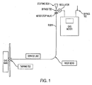
- An example of such system is shown in Fig. 1 .
- Rupture of the line or failure of fittings between the consumer property line and the served customer structure can occur for any number of reasons. Among these are digging by the customer or other party, vehicular impact, ground settling, failure of a regulator, failure of a meter, failure of fittings and earthquakes. Rupture of the line or failure of fittings can also occur on the inside customer fuel gas piping or flexible connection. Dangerous explosive conditions can arise when any such rupture occurs.
- Prior art patents show various structures for shutting off the gas flow when the flow exceeds a predetermined value, e.g. due to the downstream rupture.
- Excess flow valves are used in the natural gas industry to prevent explosive pipeline gases such as natural gas, propane, methane, coal gas, town gas, etc. from escaping when a pipe is ruptured. These safety valves will remain open during normal use, when there is backpressure downstream from the valve, but will trip (snap shut) when the downstream pressure disappears. This prevents fires and explosions when gas lines are ruptured.
- the stem of a conventional EFV such as that shown in USP 5,551,476 is spring biased opposite to the direction of gas flow.
- the poppet on the stem is held away from a valve seat by the bias spring.
- the flow is excessive such as when the service line ruptures downstream of the EFV, the forces from the flowing fluid overcome the spring bias and the poppet closes against the seat, shutting off the flow.
- the dangerous flow of combustible gas is stopped.
- the main technology barriers to retrofitting EFVs without digging have been the actual anchoring of the device in the service line.
- the anchoring of the device has been an issue since it is unacceptable to damage or otherwise alter the interior wall of the service piping.
- the method of insertion has been an issue because the valves and fittings attached to the meter set have unpredictable geometry and the bend in the service riser presents a constraint in terms of the length of the EFV and the rigidity of the installation tool.
- EP-A-1 388 697 discloses a safety device for insertion into a pipeline in which fluid circulates in an upstream and a downstream direction, comprising a tube that provides the fluid with a central circulatory passage regulated by a central valve that closes in the event of an excessive flow of this fluid.
- an annular valve closure member which is elastically malleable, mounted to the external periphery of the tube, and provides the fluid with a peripheral circulatory passage which it selectively obstructs by subjecting a radial expansion in the event of an excessive flow of fluid.
- FR-A-2 794 841 discloses an automatic flow-limiting safety valve comprises a rigid core with an envelope which inflates when excessive flow causes a pressure drop exceeding a specified limit.
- the rigid core is connected to retainers and also supports an inflatable envelope.
- the lateral wall partially delimits an internal chamber. It also faces the internal wall of the pipe.
- the admission valve is calibrated to admit fluid selectively at the upstream end of the chamber, permitting envelope inflation, when the pressure drop exceeds a given threshold.
- the inflatable envelope blocks the pipe selectively and at least partially, by radial displacement of its sidewall towards the internal wall of the pipe.
- the object of the present invention is directed to a unique EFV and installation equipment engaged to the EFV during its installation which together overcome the deficiencies and problems in the prior art discussed above.
- This is solved by the excess flow valve of the present invention according to claim 1, wherein the inventive excess flow valve adapted to be installed in a service line of a natural gas distribution system serving an existing facility, comprises:
- the present invention provides an installation equipment for fixing and leaving an excess flow valve device in a service line of a natural gas distribution system serving an existing facility, wherein the excess flow valve device has a passageway for passage of gas therethrough, the excess flow valve being engaged in a through hole of a first length of a cylindrical housing, and the cylindrical housing having an expandable tubular wall forming a part of a second length thereof, the expandable tubular wall of the housing being capable of being expanded and fixed within the service line, characterized in that the installation equipment comprises a mandrel, fluid line and hydraulic pump which are all engaged together to deliver fluid under pressure to said mandrel.
- the present invention discloses a method according to claim 11 for installing an excess flow valve in a service line of a natural gas distribution system serving an existing structure, wherein the excess flow valve has a passageway for passage of gas therethrough, the excess flow valve being engaged in a through hole of a first length of a cylindrical housing, and the cylindrical housing having an expandable tubular wall forming a part of a second length thereof, the expandable tubular wall of the housing being capable of being expanded and fixed within the service line, the method comprising forcing the cylindrical housing with the excess flow valve therewithin into the service line of the natural gas distribution system serving an existing structure; and causing the expandable tubular wall forming part of the second length of the cylindrical housing to expand so as to firmly frictionally engage the interior wall of the service line.
- the compatible EFV and installation equipment provides a new solution for retrofitting EFVs in service lines that involves no digging, thereby causing far less disruption to the community.
- the installation is effected from the customer meter set, using a hydraulically expandable element integral with the EFV that anchors the EFV inside the existing service line by the force of an interference fit.
- the engaged EFV and compatible installation equipment provides an external geometry that is initially smaller in diameter than that of the inner diameter of the service line in which the EFV is to be installed. This permits passage of the EFV through the service line and its appurtenances to the point of installation without damage.
- the EFV When the EFV has been inserted to a predetermined point in the service line, it can be expanded to the diameter needed for secure anchoring.
- the EFV is made of a material that allows for enough expansion to anchor the EFV without cracking, splitting, or otherwise deforming in an irregular manner. Put simply, this portion of the EFV is blown up like a balloon.
- the installation equipment consists of a hydraulic pump, a flexible water line, and a mandrel that slides into the unique hydraulically expandable element of the EFV.
- the anchoring force measured by a pressure gauge on the installation equipment, is high enough that the mandrel can simply be pulled out of the EFV when the expansion cycle is finished.
- the device is metal, its design would be such that the metal expands much like a balloon under the applied pressure. This would have the further benefit of insuring that no sharp edges are in contact with a plastic service line.
- installation equipment consists of a hydraulic pump, a flexible water line and a mandrel that slides into engagement with the hydraulically expandable element of the EFV.
- the anchoring force measured by a pressure gauge on the installation equipment, indicates when the expandable element has expanded to contact the service line. Thereafter, the mandrel can be withdrawn out of the EFV when the expansion cycle has ended.
- EFV 1 shown in Fig. 2 is intended for installation in an existing conventional natural gas service system such as that shown in Fig. 1 to prevent escaping gas entering the home of a customer from a ruptured gas line downstream from the gas meter.
- the distribution system of Fig. 1 is shown connected between a tapping tee on a gas main and a gas meter located in the home of the customer.
- the service line shown in the system is normally buried after these connections have been made.
- Installation of the EFV 1 is accomplished by inserting it through the bypass tee shown in Fig. 1 on the inlet side of the gas meter and fixing it to the inner wall of the gas pipe which extends to the gas main. Insertion under pressure is accomplished by way of a "stuffing box", a conventional device that consists of a sealed chamber which is attached to the bypass tee and allows control of a sliding rod or cable (not shown). One end of the rod or cable is outside of the stuffing box, allowing direct control by the operator while the opposite end is sealed inside the pressurized system. The seal is maintained via a gland nut and elastomer that compresses around the rod or cable when the nut is tightened.
- EFV 1 has a continuous cylindrical housing 10 made preferably of metal that has the same outer diameter throughout its length and a through hole 11 that has inner diameters over selected lengths of the housing 10 which are different from each other so as to support the different functions of housing portions 2, 4 of housing 10 discussed below.
- Portion 2 extends over a length 6 of cylindrical housing 10 and houses conventional hardware 12 similar to that shown in USP 5,551,476 to control the opening and closing of an EFV valve therein.
- hardware 12 is not an inventive feature of the present invention, it will not be addressed further.
- Portion 4 extends over a length 8 of cylindrical housing 10 and is integrally formed as a unit with portion 2. Located within the length 8 of portion 4 is a laterally expandable wall 14. The inner diameter 16 of through hole 11 over the length of wall 14 is larger than inner diameter 18 located at opposite ends 15, 17 of portion 4. Thus, expandable wall 14 is thinner and more flexible than the wall of housing 10 located at opposite ends of portion 4.
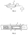
- Fig. 4 shows the installation equipment 20 which serves to locate and fix EFV 1 at a predetermined position in the service line downstream from the customer's gas meter.
- This equipment consists of a hydraulic pump 22, flexible fluid line 24, and a mandrel 26 designed for sealed engagement with opposite ends 15, 17 of portion 4.
- Mandrel 26 comprises a cylindrical housing 28 a closed first end 30 and a second end 32 having an inlet engaged to an end of fluid line 24. The other end of fluid line 24 is engaged to hydraulic pump 22.
- Housing 26 is closed with the exception of fluid outlet hole 34 and the inlet in its second end 32. Finally, elastic O-rings 36 are fixed to housing 26 near opposite ends 30, 32 so as to be spaced apart substantially the same distance as opposite ends 15, 17 of portion 4 of EFV 1.
- Retrofitting EFV 1 into an existing gas service line begins with inserting mandrel 26 into EFV 1 as shown in Fig. 5 so that O-rings 36 are respectively engaged to opposite ends 15, 17 of portion 4 to seal mandrel 26 in portion 4. This engagement creates an annular sealed space 37 and confined between mandrel 26 expandable wall 14.
- mandrel 26 After mandrel 26 is engaged in EFV 1, they can be easily inserted into service line 38 as shown in Fig. 5 since the outer diameter of the engaged EFV 1 and mandrel 26 are smaller than that of the inner diameter of service line 38.
- the engaged EFV 1 and mandrel 26 can then be moved to a predetermined position in service line 38 by manipulation of flexible fluid line 24.
- an operator can initiate operation of hydraulic pump 22 to force fluid through fluid line 24 into mandrel 26 and out fluid outlet hole 34 into sealed space 37.
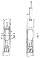
- the pressure created by the influx of fluid into sealed and confined space 37 results in the lateral expansion of expandable wall 14 into fixed engagement with the inner wall of service line 38 as shown in Fig. 6 .
- Figs. 3 and 8 respectively show cross-sections of annular expandable wall 14 before and after its expansion by the fluid pressure created by hydraulic pump 22 in annular space 37.
Landscapes
- Engineering & Computer Science (AREA)
- General Engineering & Computer Science (AREA)
- Mechanical Engineering (AREA)
- Pipe Accessories (AREA)
- Safety Valves (AREA)
- Valve Housings (AREA)
Abstract
Description
- The present invention relates to an excess flow valve (EFV), an installation equipment relating thereto and a method for installing the excess flow valve into an existing gas service line.
- Conventional combustible gas distribution systems bring gas from a street main below ground level, through a tapping tee, a service line, a riser above ground level, a meter cock, a regulator, a meter and then into the customer's structure. An example of such system is shown in
Fig. 1 . - Rupture of the line or failure of fittings between the consumer property line and the served customer structure can occur for any number of reasons. Among these are digging by the customer or other party, vehicular impact, ground settling, failure of a regulator, failure of a meter, failure of fittings and earthquakes. Rupture of the line or failure of fittings can also occur on the inside customer fuel gas piping or flexible connection. Dangerous explosive conditions can arise when any such rupture occurs.
- Prior art patents show various structures for shutting off the gas flow when the flow exceeds a predetermined value, e.g. due to the downstream rupture. Excess flow valves are used in the natural gas industry to prevent explosive pipeline gases such as natural gas, propane, methane, coal gas, town gas, etc. from escaping when a pipe is ruptured. These safety valves will remain open during normal use, when there is backpressure downstream from the valve, but will trip (snap shut) when the downstream pressure disappears. This prevents fires and explosions when gas lines are ruptured.
- In operation, the stem of a conventional EFV such as that shown in
USP 5,551,476 is spring biased opposite to the direction of gas flow. Under normal conditions the poppet on the stem is held away from a valve seat by the bias spring. When the flow is excessive such as when the service line ruptures downstream of the EFV, the forces from the flowing fluid overcome the spring bias and the poppet closes against the seat, shutting off the flow. Thus, the dangerous flow of combustible gas is stopped. - Presently, in order to install an EFV in an existing service line a hole or trench must be dug, the service line pressure must be reduced to zero, and the service line must be cut. This is not only expensive, time consuming, and disruptive to customers and traffic flows, it is also impractical in terms of the human resources required.
- The main technology barriers to retrofitting EFVs without digging have been the actual anchoring of the device in the service line. The anchoring of the device has been an issue since it is unacceptable to damage or otherwise alter the interior wall of the service piping. The method of insertion has been an issue because the valves and fittings attached to the meter set have unpredictable geometry and the bend in the service riser presents a constraint in terms of the length of the EFV and the rigidity of the installation tool.
- Closest prior art
EP-A-1 388 697 discloses a safety device for insertion into a pipeline in which fluid circulates in an upstream and a downstream direction, comprising a tube that provides the fluid with a central circulatory passage regulated by a central valve that closes in the event of an excessive flow of this fluid. There is an annular valve closure member which is elastically malleable, mounted to the external periphery of the tube, and provides the fluid with a peripheral circulatory passage which it selectively obstructs by subjecting a radial expansion in the event of an excessive flow of fluid. -
FR-A-2 794 841 - The object of the present invention is directed to a unique EFV and installation equipment engaged to the EFV during its installation which together overcome the deficiencies and problems in the prior art discussed above.
This is solved by the excess flow valve of the present invention according to claim 1, wherein the inventive excess flow valve adapted to be installed in a service line of a natural gas distribution system serving an existing facility, comprises: - a cylindrical housing having a portion with a first length and a portion with a second length and a through hole extending therethrough for passage therethrough of gas. The EFV being engaged in said through hole of said first length and an expandable tubular wall forms a portion of the second length of the cylindrical housing, wherein the expandable tubular wall being adapted to and capable of anchoring the EFV and the cylindrical housing within the service line when the expandable tubular wall has been expanded within the service line. The EFV and the cylindrical housing are free of any other means to anchor the cylindrical housing within the service line. When said expandable tubular wall is expanded in an annular configuration in the service line, the EFV and the cylindrical housing are fixed and permanently left in the service line to seal the service line for the passage of gas therethrough except through the EFV from the time of initial installation of the cylindrical housing with the EFV therewithin.
- Additionally, said problems of prior art are solved by the present invention according to
claim 6, providing an installation equipment for fixing and leaving an excess flow valve device in a service line of a natural gas distribution system serving an existing facility, wherein the excess flow valve device has a passageway for passage of gas therethrough, the excess flow valve being engaged in a through hole of a first length of a cylindrical housing, and the cylindrical housing having an expandable tubular wall forming a part of a second length thereof, the expandable tubular wall of the housing being capable of being expanded and fixed within the service line, characterized in that the installation equipment comprises a mandrel, fluid line and hydraulic pump which are all engaged together to deliver fluid under pressure to said mandrel. - Additionally, the present invention a discloses a method according to
claim 11 for installing an excess flow valve in a service line of a natural gas distribution system serving an existing structure, wherein the excess flow valve has a passageway for passage of gas therethrough, the excess flow valve being engaged in a through hole of a first length of a cylindrical housing, and the cylindrical housing having an expandable tubular wall forming a part of a second length thereof, the expandable tubular wall of the housing being capable of being expanded and fixed within the service line, the method comprising forcing the cylindrical housing with the excess flow valve therewithin into the service line of the natural gas distribution system serving an existing structure; and causing the expandable tubular wall forming part of the second length of the cylindrical housing to expand so as to firmly frictionally engage the interior wall of the service line. - The compatible EFV and installation equipment provides a new solution for retrofitting EFVs in service lines that involves no digging, thereby causing far less disruption to the community. The installation is effected from the customer meter set, using a hydraulically expandable element integral with the EFV that anchors the EFV inside the existing service line by the force of an interference fit.
- The engaged EFV and compatible installation equipment provides an external geometry that is initially smaller in diameter than that of the inner diameter of the service line in which the EFV is to be installed. This permits passage of the EFV through the service line and its appurtenances to the point of installation without damage.
- When the EFV has been inserted to a predetermined point in the service line, it can be expanded to the diameter needed for secure anchoring. The EFV is made of a material that allows for enough expansion to anchor the EFV without cracking, splitting, or otherwise deforming in an irregular manner. Put simply, this portion of the EFV is blown up like a balloon.
- The method for the actual hydraulic expansion is and has been for some time in the public domain in the form of a method of power plant steam turbine condenser tube sleeving (repair), however the concept for using this for anchoring an EFV is entirely new and constitutes a secondary component of this original idea and application.
- The installation equipment consists of a hydraulic pump, a flexible water line, and a mandrel that slides into the unique hydraulically expandable element of the EFV. The anchoring force, measured by a pressure gauge on the installation equipment, is high enough that the mandrel can simply be pulled out of the EFV when the expansion cycle is finished.
- Thus, the features of the EFV according to the invention in cooperation with its installation equipment are intended to permit a user to:
- (1) Retrofit the EFV in the customer's meter piping while the service line remains pressurized.
- (2) Insert the EFV through the service line up to the tee that is attached to the gas main, and
- (3) Use hydraulic pressure to expand a specific portion of the EFV so as to contact the inside of the service line and lock the EFV in place.
- Though the device is metal, its design would be such that the metal expands much like a balloon under the applied pressure. This would have the further benefit of insuring that no sharp edges are in contact with a plastic service line.
- As indicated above, installation equipment consists of a hydraulic pump, a flexible water line and a mandrel that slides into engagement with the hydraulically expandable element of the EFV. The anchoring force, measured by a pressure gauge on the installation equipment, indicates when the expandable element has expanded to contact the service line. Thereafter, the mandrel can be withdrawn out of the EFV when the expansion cycle has ended.
- The present invention will be more apparent from the following detailed description of an embodiment taken in conjunction with the following drawings, wherein:
-
FIG. 1 : shows a conventional natural gas distribution system; -
FIG. 2 : shows an elevation view of the EFV according to the invention before its use; -
FIG. 3 : shows a cross-sectional view along section line 3- 3 ofFig. 2 ; -
FIG. 4 : shows an elevation view of the mandrel, fluid line and hydraulic pump; -
FIG. 5 : shows an elevation view of the mandrel and fluid line ofFig. 4 inserted into the EFV ofFig. 2 in the service line prior to engagement of the EFV in the service line; -
FIG. 6 : shows the EFV ofFig. 5 expanded into engagement with the service line; -
FIG. 7 : shows the mandrel and fluid line ofFig. 6 withdrawn from the expanded EFV ofFig. 6 , and -
FIG. 8 : shows a cross-sectional view along section line 8- 8 ofFig. 6 with the service line not shown. - EFV 1 shown in
Fig. 2 is intended for installation in an existing conventional natural gas service system such as that shown inFig. 1 to prevent escaping gas entering the home of a customer from a ruptured gas line downstream from the gas meter. The distribution system ofFig. 1 is shown connected between a tapping tee on a gas main and a gas meter located in the home of the customer. The service line shown in the system is normally buried after these connections have been made. - Installation of the EFV 1 is accomplished by inserting it through the bypass tee shown in
Fig. 1 on the inlet side of the gas meter and fixing it to the inner wall of the gas pipe which extends to the gas main. Insertion under pressure is accomplished by way of a "stuffing box", a conventional device that consists of a sealed chamber which is attached to the bypass tee and allows control of a sliding rod or cable (not shown). One end of the rod or cable is outside of the stuffing box, allowing direct control by the operator while the opposite end is sealed inside the pressurized system. The seal is maintained via a gland nut and elastomer that compresses around the rod or cable when the nut is tightened. Such a device is well known within the industry and accordingly not an inventive feature of the claimed invention. The progression of drawings fromFig. 2 through Fig. 8 illustrates the structural components and steps involved in the installation of EFV 1 in such gas pipes and removal of the installation equipment after the installation. - As shown in
Fig. 2 , EFV 1 has a continuouscylindrical housing 10 made preferably of metal that has the same outer diameter throughout its length and a throughhole 11 that has inner diameters over selected lengths of thehousing 10 which are different from each other so as to support the different functions ofhousing portions housing 10 discussed below. -
Portion 2 extends over alength 6 ofcylindrical housing 10 and housesconventional hardware 12 similar to that shown inUSP 5,551,476 to control the opening and closing of an EFV valve therein. Ashardware 12 is not an inventive feature of the present invention, it will not be addressed further. -
Portion 4 extends over alength 8 ofcylindrical housing 10 and is integrally formed as a unit withportion 2. Located within thelength 8 ofportion 4 is a laterallyexpandable wall 14. Theinner diameter 16 of throughhole 11 over the length ofwall 14 is larger thaninner diameter 18 located at opposite ends 15, 17 ofportion 4. Thus,expandable wall 14 is thinner and more flexible than the wall ofhousing 10 located at opposite ends ofportion 4. -
Fig. 4 shows theinstallation equipment 20 which serves to locate and fix EFV 1 at a predetermined position in the service line downstream from the customer's gas meter. This equipment consists of ahydraulic pump 22,flexible fluid line 24, and amandrel 26 designed for sealed engagement with opposite ends 15, 17 ofportion 4. -
Mandrel 26 comprises a cylindrical housing 28 a closedfirst end 30 and asecond end 32 having an inlet engaged to an end offluid line 24. The other end offluid line 24 is engaged tohydraulic pump 22. -
Housing 26 is closed with the exception offluid outlet hole 34 and the inlet in itssecond end 32. Finally, elastic O-rings 36 are fixed tohousing 26 near opposite ends 30, 32 so as to be spaced apart substantially the same distance as opposite ends 15, 17 ofportion 4 of EFV 1. - Retrofitting EFV 1 into an existing gas service line begins with inserting
mandrel 26 into EFV 1 as shown inFig. 5 so that O-rings 36 are respectively engaged to opposite ends 15, 17 ofportion 4 to sealmandrel 26 inportion 4. This engagement creates an annular sealedspace 37 and confined betweenmandrel 26expandable wall 14. After mandrel 26 is engaged in EFV 1, they can be easily inserted intoservice line 38 as shown inFig. 5 since the outer diameter of the engaged EFV 1 andmandrel 26 are smaller than that of the inner diameter ofservice line 38. The engaged EFV 1 andmandrel 26 can then be moved to a predetermined position inservice line 38 by manipulation offlexible fluid line 24. - After the engaged EFV 1 and
mandrel 26 have reached the selected position inservice line 38, an operator can initiate operation ofhydraulic pump 22 to force fluid throughfluid line 24 intomandrel 26 and outfluid outlet hole 34 into sealedspace 37. The pressure created by the influx of fluid into sealed and confinedspace 37 results in the lateral expansion ofexpandable wall 14 into fixed engagement with the inner wall ofservice line 38 as shown inFig. 6 . -
Figs. 3 and8 respectively show cross-sections of annularexpandable wall 14 before and after its expansion by the fluid pressure created byhydraulic pump 22 inannular space 37. - After the operator is satisfied that EFV 1 has been successfully fixed in
service line 38 by engagement ofexpandable wall 14 against the inner wall ofservice line 38 as shown inFig. 6 , thehydraulic pump 22 is turned off. This permits removal ofmandrel 26 from the EFV 1 engaged in the service line by withdrawing the fluid line from the service line.
Claims (15)
- An excess flow valve (EFV) (1) adapted to be installed in a service line (38) of a natural gas distribution system serving an existing facility, said EFV comprising:a cylindrical housing (10) having a portion (2) with a first length (6) and a portion (4) with a second length (8) and a through hole (11) extending therethrough for passage therethrough of gas;the EFV being engaged in said through hole (11) of said first length (6); characterised by said EFV further comprisingan expandable tubular wall (14) forming a portion of the second length (8) of the cylindrical housing (10);wherein the expandable tubular wall (14) being adapted to and capable of anchoring the EFV and the cylindrical housing (10) within the service line when the expandable tubular wall (14) has been expanded within the service line;wherein the EFV and the cylindrical housing (10) being free of any other means to anchor the cylindrical housing (10) within the service line;wherein when said expandable tubular wall (14) is expanded in an annular configuration in the service line, the EFV and the cylindrical housing (10) are fixed and permanently left in the service line to seal the service line for the passage of gas therethrough except through the EFV from the time of initial installation of the cylindrical housing (10) with the EFV therewithin.
- The excess flow valve (1) according to claim 1, wherein said first length (6) and said second length (8) are integrally formed together as a unit.
- The excess flow valve (1) according to claims 1 or 2, wherein an annular wall at each end of said second length (8) of said EFV housing is thicker than the expandable wall between the ends of said second length (8).
- The excess flow valve (1) of claim 1 wherein said tubular wall is formed of metal.
- The excess flow valve (1) according to any of claims 1-4 when used in situ within the service line, with said tubular wall being expanded in the service line whereby the EFV is able to be fixed and left in place.
- Installation equipment (20) for fixing and leaving an excess flow valve device (1) in a service line (38) of a natural gas distribution system serving an existing facility, wherein the excess flow valve device (1) has a passageway for passage of gas therethrough, the excess flow valve (1) being engaged in a through hole (11) of a first length (6) of a cylindrical housing (10), and the cylindrical housing (10) having an expandable tubular wall (14) forming a part of a second length (8) thereof, the expandable tubular wall (14) of the housing (10) being capable of being expanded and fixed within the service line (38), characterized in that
the installation equipment comprises a mandrel (26), fluid line (24) and hydraulic pump (22) which are all engaged together to deliver fluid under pressure to said mandrel (26). - The installation equipment (20) according to claim 6, wherein the mandrel (26) includes a cylindrical housing (28) engaged to the fluid line (24), said mandrel housing (28) having a pair of O-rings (36) respectively fixed at opposite ends thereof and a fluid outlet hole (34) located between the O-rings (36).
- The installation equipment (20) according to claim 7, wherein said O-rings (36) of the mandrel (26) are respectively fixed against the annular wall (14) at each end of the second length (8) so as to form a space between the expandable wall (14) and the mandrel (26) when the mandrel (26) when is engaged in the EFV (1),
wherein when fluid is delivered under pressure to the mandrel (26), the excess flow valve device (1) become fixed in the service line (38). - The installation equipment (20) according to claim 8, wherein the diameter of the EFV housing (10), the mandrel housing (28) and the fluid line (24) are each smaller than that of the service line (38).
- The installation equipment (20) according to claim 7, wherein the pair of O-rings (36) are spaced apart the distance substantially equal to that between the ends of said second length (8).
- A method for installing an excess flow valve (1) in a service line (38) of a natural gas distribution system serving an existing structure, wherein the excess flow valve (1) has a passageway for passage of gas therethrough, the excess flow valve (1) being engaged in a through hole (11) of a first length (6) of a cylindrical housing (10), and the cylindrical housing (10) having an expandable tubular wall (14) forming a part of a second length (8) thereof, the expandable tubular wall (14) of the housing (10) being capable of being expanded and fixed within the service line (38), the method comprising
forcing the cylindrical housing (10) with the excess flow valve (1) therewithin into the service line (38) of the natural gas distribution system serving an existing structure; and
causing the expandable tubular wall (14) forming part of the second length (8) of the cylindrical housing (10) to expand so as to firmly frictionally engage the interior wall of the service line (38). - The method of claim 11, wherein the expandable tubular wall (14) of the second length (8) of the cylindrical housing (10) is caused to expand by delivering fluid under pressure thereto.
- The method of claim 11 or claim 12, wherein the cylindrical housing (10) with the excess flow valve (1) therewithin is forced to a position within the service line (38) by use of a mandrel (26).
- A method according to any one of claims 11-13, wherein the location in the service line (38), into which the cylindrical housing (10) with the excess flow valve (1) therein is delivered, is underground.
- The method of any one of claims 11-14, wherein the service line has a bend therein and the cylindrical housing (10) with the excess flow valve (1) therewithin is forced around the bend and downstream therefrom to the location at which the expansion takes place.
Priority Applications (2)
| Application Number | Priority Date | Filing Date | Title |
|---|---|---|---|
| EP07015042A EP2020546B1 (en) | 2007-07-31 | 2007-07-31 | Excess flow valves |
| AT07015042T ATE514885T1 (en) | 2007-07-31 | 2007-07-31 | OUTFLOW VALVES |
Applications Claiming Priority (1)
| Application Number | Priority Date | Filing Date | Title |
|---|---|---|---|
| EP07015042A EP2020546B1 (en) | 2007-07-31 | 2007-07-31 | Excess flow valves |
Publications (2)
| Publication Number | Publication Date |
|---|---|
| EP2020546A1 EP2020546A1 (en) | 2009-02-04 |
| EP2020546B1 true EP2020546B1 (en) | 2011-06-29 |
Family
ID=39012152
Family Applications (1)
| Application Number | Title | Priority Date | Filing Date |
|---|---|---|---|
| EP07015042A Active EP2020546B1 (en) | 2007-07-31 | 2007-07-31 | Excess flow valves |
Country Status (2)
| Country | Link |
|---|---|
| EP (1) | EP2020546B1 (en) |
| AT (1) | ATE514885T1 (en) |
Cited By (1)
| Publication number | Priority date | Publication date | Assignee | Title |
|---|---|---|---|---|
| US11371622B2 (en) | 2017-07-20 | 2022-06-28 | Hubbell Incorporated | Excess flow valve assemblies |
Family Cites Families (3)
| Publication number | Priority date | Publication date | Assignee | Title |
|---|---|---|---|---|
| US5551476A (en) | 1995-01-05 | 1996-09-03 | Umac Incorporated | Balanced-flow gas safety valve |
| FR2794841B1 (en) | 1999-06-10 | 2001-08-31 | Gaz De France | UNIVERSAL SECURITY DEVICE AND METHOD FOR PROTECTING A PIPELINE |
| FR2843437B1 (en) | 2002-08-09 | 2004-09-24 | Gaz De France | SAFETY DEVICE WITH AUTOMATIC TRIGGER AND DOUBLE VALVE FOR CONTROLLING THE FLOW OF A FLUID |
-
2007
- 2007-07-31 EP EP07015042A patent/EP2020546B1/en active Active
- 2007-07-31 AT AT07015042T patent/ATE514885T1/en active
Cited By (1)
| Publication number | Priority date | Publication date | Assignee | Title |
|---|---|---|---|---|
| US11371622B2 (en) | 2017-07-20 | 2022-06-28 | Hubbell Incorporated | Excess flow valve assemblies |
Also Published As
| Publication number | Publication date |
|---|---|
| EP2020546A1 (en) | 2009-02-04 |
| ATE514885T1 (en) | 2011-07-15 |
Similar Documents
| Publication | Publication Date | Title |
|---|---|---|
| US8776826B2 (en) | Excess flow valves | |
| AU627821B2 (en) | Method for repairing pipes | |
| CA2872361C (en) | Resilient plug apparatus and method of use | |
| US5740830A (en) | Testing of plumbing installations | |
| US7311114B2 (en) | Cross-line plugging system | |
| JP2001508877A (en) | Investigating leaks | |
| US5511578A (en) | Tool for installing a stopper in a gas conduit wall | |
| US20200290098A1 (en) | Systems and methods for cleaning a pressurized pipe | |
| US6679949B2 (en) | Method and device to allow a rigid pig to pass into a flow pipe which requires the use of a hollow flow-constricting device | |
| US6345641B1 (en) | Fluid-activatable device for shut-off under excess flow conditions | |
| EP2020546A1 (en) | Excess flow valves | |
| US5267612A (en) | Friction plug for a high pressure pipe | |
| US6962165B2 (en) | Automatically-actuated safety device with a double-seated valve to regulate the flow rate of a fluid | |
| AU2019232932A1 (en) | Systems and methods for accessing and monitoring a fluid within a pressurized pipe | |
| KR20130026470A (en) | Temporary piping system for the selected range flow from the whole piping system | |
| US11254045B2 (en) | Method and system for lining pipes | |
| US10527217B2 (en) | Launch system for underground gas main stop-off station | |
| KR20080008372A (en) | Cross-Line Plugging System and Lock Plug | |
| AU715649C (en) | Testing of plumbing installations and plumbing tool | |
| JP2002213645A (en) | Method of installing temporary pipe | |
| GB2359123A (en) | Valve with separable actuator | |
| AWWA Steel Pipe Committee Report | CHAPTER 11: Fittings and Appurtenances |
Legal Events
| Date | Code | Title | Description |
|---|---|---|---|
| PUAI | Public reference made under article 153(3) epc to a published international application that has entered the european phase |
Free format text: ORIGINAL CODE: 0009012 |
|
| AK | Designated contracting states |
Kind code of ref document: A1 Designated state(s): AT BE BG CH CY CZ DE DK EE ES FI FR GB GR HU IE IS IT LI LT LU LV MC MT NL PL PT RO SE SI SK TR |
|
| AX | Request for extension of the european patent |
Extension state: AL BA HR MK RS |
|
| 17P | Request for examination filed |
Effective date: 20090715 |
|
| AKX | Designation fees paid |
Designated state(s): AT DE FR GB IT |
|
| 17Q | First examination report despatched |
Effective date: 20091221 |
|
| GRAP | Despatch of communication of intention to grant a patent |
Free format text: ORIGINAL CODE: EPIDOSNIGR1 |
|
| GRAS | Grant fee paid |
Free format text: ORIGINAL CODE: EPIDOSNIGR3 |
|
| GRAA | (expected) grant |
Free format text: ORIGINAL CODE: 0009210 |
|
| AK | Designated contracting states |
Kind code of ref document: B1 Designated state(s): AT DE FR GB IT |
|
| REG | Reference to a national code |
Ref country code: GB Ref legal event code: FG4D |
|
| REG | Reference to a national code |
Ref country code: DE Ref legal event code: R096 Ref document number: 602007015462 Country of ref document: DE Effective date: 20110818 |
|
| PLBE | No opposition filed within time limit |
Free format text: ORIGINAL CODE: 0009261 |
|
| STAA | Information on the status of an ep patent application or granted ep patent |
Free format text: STATUS: NO OPPOSITION FILED WITHIN TIME LIMIT |
|
| 26N | No opposition filed |
Effective date: 20120330 |
|
| REG | Reference to a national code |
Ref country code: DE Ref legal event code: R097 Ref document number: 602007015462 Country of ref document: DE Effective date: 20120330 |
|
| REG | Reference to a national code |
Ref country code: FR Ref legal event code: PLFP Year of fee payment: 9 |
|
| REG | Reference to a national code |
Ref country code: GB Ref legal event code: 732E Free format text: REGISTERED BETWEEN 20150730 AND 20150805 |
|
| REG | Reference to a national code |
Ref country code: DE Ref legal event code: R082 Ref document number: 602007015462 Country of ref document: DE Representative=s name: BECKER, KURIG, STRAUS, DE Ref country code: DE Ref legal event code: R081 Ref document number: 602007015462 Country of ref document: DE Owner name: GASBREAKER INC., MALVERN, US Free format text: FORMER OWNER: UMAC INCORPORATED, MALVERN, PA 19355-1234, US Ref country code: DE Ref legal event code: R081 Ref document number: 602007015462 Country of ref document: DE Owner name: CONTINENTAL INDUSTRIES DIVISION OF BURNDY LLC , US Free format text: FORMER OWNER: UMAC INCORPORATED, MALVERN, PA 19355-1234, US |
|
| REG | Reference to a national code |
Ref country code: FR Ref legal event code: TP Owner name: GASBREAKER INC., US Effective date: 20160108 |
|
| REG | Reference to a national code |
Ref country code: DE Ref legal event code: R082 Ref document number: 602007015462 Country of ref document: DE Representative=s name: BECKER-KURIG-STRAUS PATENTANWAELTE PARTNERSCHA, DE Ref country code: DE Ref legal event code: R082 Ref document number: 602007015462 Country of ref document: DE Representative=s name: BECKER & KURIG PARTNERSCHAFT PATENTANWAELTE MB, DE Ref country code: DE Ref legal event code: R082 Ref document number: 602007015462 Country of ref document: DE Representative=s name: BECKER & KURIG PARTNERSCHAFT PATENTANWAELTE PA, DE Ref country code: DE Ref legal event code: R082 Ref document number: 602007015462 Country of ref document: DE Representative=s name: BECKER, KURIG, STRAUS, DE Ref country code: DE Ref legal event code: R081 Ref document number: 602007015462 Country of ref document: DE Owner name: CONTINENTAL INDUSTRIES DIVISION OF BURNDY LLC , US Free format text: FORMER OWNER: GASBREAKER INC., MALVERN, PA., US |
|
| REG | Reference to a national code |
Ref country code: FR Ref legal event code: PLFP Year of fee payment: 10 |
|
| REG | Reference to a national code |
Ref country code: GB Ref legal event code: 732E Free format text: REGISTERED BETWEEN 20160915 AND 20160921 |
|
| REG | Reference to a national code |
Ref country code: AT Ref legal event code: PC Ref document number: 514885 Country of ref document: AT Kind code of ref document: T Owner name: GASBREAKER INC., US Effective date: 20160831 |
|
| REG | Reference to a national code |
Ref country code: FR Ref legal event code: TP Owner name: CONTINENTAL INDUSTRIES DIVISION OF BURNDY LLC, US Effective date: 20161108 |
|
| REG | Reference to a national code |
Ref country code: FR Ref legal event code: PLFP Year of fee payment: 11 |
|
| REG | Reference to a national code |
Ref country code: FR Ref legal event code: PLFP Year of fee payment: 12 |
|
| PGFP | Annual fee paid to national office [announced via postgrant information from national office to epo] |
Ref country code: ES Payment date: 20180903 Year of fee payment: 10 |
|
| PG25 | Lapsed in a contracting state [announced via postgrant information from national office to epo] |
Ref country code: IT Free format text: LAPSE BECAUSE OF NON-PAYMENT OF DUE FEES Effective date: 20190731 |
|
| P01 | Opt-out of the competence of the unified patent court (upc) registered |
Effective date: 20230530 |
|
| PGFP | Annual fee paid to national office [announced via postgrant information from national office to epo] |
Ref country code: GB Payment date: 20250612 Year of fee payment: 19 |
|
| PGFP | Annual fee paid to national office [announced via postgrant information from national office to epo] |
Ref country code: FR Payment date: 20250612 Year of fee payment: 19 |
|
| PGFP | Annual fee paid to national office [announced via postgrant information from national office to epo] |
Ref country code: DE Payment date: 20250616 Year of fee payment: 19 |
|
| PGFP | Annual fee paid to national office [announced via postgrant information from national office to epo] |
Ref country code: AT Payment date: 20250625 Year of fee payment: 19 |