EP2020542A1 - Seal assembly - Google Patents
Seal assembly Download PDFInfo
- Publication number
- EP2020542A1 EP2020542A1 EP08161286A EP08161286A EP2020542A1 EP 2020542 A1 EP2020542 A1 EP 2020542A1 EP 08161286 A EP08161286 A EP 08161286A EP 08161286 A EP08161286 A EP 08161286A EP 2020542 A1 EP2020542 A1 EP 2020542A1
- Authority
- EP
- European Patent Office
- Prior art keywords
- stator
- seal assembly
- flexure
- movable
- seal
- Prior art date
- Legal status (The legal status is an assumption and is not a legal conclusion. Google has not performed a legal analysis and makes no representation as to the accuracy of the status listed.)
- Withdrawn
Links
Images







Classifications
-
- F—MECHANICAL ENGINEERING; LIGHTING; HEATING; WEAPONS; BLASTING
- F16—ENGINEERING ELEMENTS AND UNITS; GENERAL MEASURES FOR PRODUCING AND MAINTAINING EFFECTIVE FUNCTIONING OF MACHINES OR INSTALLATIONS; THERMAL INSULATION IN GENERAL
- F16J—PISTONS; CYLINDERS; SEALINGS
- F16J15/00—Sealings
- F16J15/16—Sealings between relatively-moving surfaces
- F16J15/164—Sealings between relatively-moving surfaces the sealing action depending on movements; pressure difference, temperature or presence of leaking fluid
-
- F—MECHANICAL ENGINEERING; LIGHTING; HEATING; WEAPONS; BLASTING
- F01—MACHINES OR ENGINES IN GENERAL; ENGINE PLANTS IN GENERAL; STEAM ENGINES
- F01D—NON-POSITIVE DISPLACEMENT MACHINES OR ENGINES, e.g. STEAM TURBINES
- F01D11/00—Preventing or minimising internal leakage of working-fluid, e.g. between stages
- F01D11/005—Sealing means between non relatively rotating elements
-
- F—MECHANICAL ENGINEERING; LIGHTING; HEATING; WEAPONS; BLASTING
- F01—MACHINES OR ENGINES IN GENERAL; ENGINE PLANTS IN GENERAL; STEAM ENGINES
- F01D—NON-POSITIVE DISPLACEMENT MACHINES OR ENGINES, e.g. STEAM TURBINES
- F01D11/00—Preventing or minimising internal leakage of working-fluid, e.g. between stages
- F01D11/02—Preventing or minimising internal leakage of working-fluid, e.g. between stages by non-contact sealings, e.g. of labyrinth type
- F01D11/04—Preventing or minimising internal leakage of working-fluid, e.g. between stages by non-contact sealings, e.g. of labyrinth type using sealing fluid, e.g. steam
-
- F—MECHANICAL ENGINEERING; LIGHTING; HEATING; WEAPONS; BLASTING
- F01—MACHINES OR ENGINES IN GENERAL; ENGINE PLANTS IN GENERAL; STEAM ENGINES
- F01D—NON-POSITIVE DISPLACEMENT MACHINES OR ENGINES, e.g. STEAM TURBINES
- F01D25/00—Component parts, details, or accessories, not provided for in, or of interest apart from, other groups
- F01D25/24—Casings; Casing parts, e.g. diaphragms, casing fastenings
- F01D25/246—Fastening of diaphragms or stator-rings
-
- F—MECHANICAL ENGINEERING; LIGHTING; HEATING; WEAPONS; BLASTING
- F16—ENGINEERING ELEMENTS AND UNITS; GENERAL MEASURES FOR PRODUCING AND MAINTAINING EFFECTIVE FUNCTIONING OF MACHINES OR INSTALLATIONS; THERMAL INSULATION IN GENERAL
- F16J—PISTONS; CYLINDERS; SEALINGS
- F16J15/00—Sealings
- F16J15/44—Free-space packings
- F16J15/445—Free-space packings with means for adjusting the clearance
-
- F—MECHANICAL ENGINEERING; LIGHTING; HEATING; WEAPONS; BLASTING
- F16—ENGINEERING ELEMENTS AND UNITS; GENERAL MEASURES FOR PRODUCING AND MAINTAINING EFFECTIVE FUNCTIONING OF MACHINES OR INSTALLATIONS; THERMAL INSULATION IN GENERAL
- F16J—PISTONS; CYLINDERS; SEALINGS
- F16J15/00—Sealings
- F16J15/44—Free-space packings
- F16J15/447—Labyrinth packings
- F16J15/4476—Labyrinth packings with radial path
Definitions
- the invention generally relates to gas turbine engines and more specifically to seal assemblies used with gas turbine engines.
- Gas turbine engines displace large volumes of pressurized fluid, such as air through the engine fluid flowpath, during operation.
- Seal assemblies prevent the fluid from leaking undesirably by restricting fluid flow from areas of higher pressure to areas of lower pressure.
- the seal assemblies may be positioned between engine stationary and rotating members. The seals compensate for transient variations in the gaps between adjacent engine component parts.
- seal assemblies Because of the working environment of the seal assemblies, and/or the operating environment, at least some known seal assemblies may deteriorate over time. If the seals do not provide the required seal, fluid will leak past the seal detrimentally affecting the operation of the engine. Fluid leakage through gas turbine engine seal assemblies may significantly increase fuel consumption and adversely affect engine efficiency. Additionally, fluid leakage may cause damage to other engine components and increase overall engine maintenance costs.
- seal assemblies such as the seal assembly described in U.S. Patent No. 5,284,347 , for example, use aspirating air to control leakage.
- the aspirating air prevents the rotating member from contacting the stationary member to facilitate accommodating transient variations in the gap defined between the rotating and stationary members with little or no deterioration of the seal over the life of the seal assembly.
- seal assemblies may be complex to install in the engine, and the weight of such assemblies will increase engine weight which has a direct negative impact on engine performance.
- the operating efficiency of such seal assemblies may be contingent on the tolerances between the rotating and stationary members.
- a seal assembly comprising a first movable stator member movable between a sealing position and a non-sealing position, a second fixed stator member, the first stator member being movable relative to the second stator member, the seal assembly further comprising at least one flexure member coupled to the second stator member, and at least one biasing member coupled between the at least one flexure and the movable stator for biasing the movable stator to a non-sealing position.
- Figure 1 is a schematic illustration of an exemplary gas turbine engine
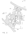
- Figure 2 is a cross-sectional view of an exemplary seal assembly that may be used with the gas turbine engine shown in Figure 1 , with a movable sealing member in a first position;
- Figure 3 is a cross-sectional view of the exemplary seal assembly of Figure 2 with the movable sealing member in a second sealing position;
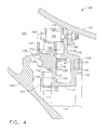
- Figure 4 is a cross-sectional view of an exemplary seal assembly that may be used with the gas turbine engine shown in Figure 1 , with a movable sealing member in a first open position;
- Figure 5 is a cross-sectional view of the exemplary seal assembly of Figure 4 with the movable sealing member in a second sealing position;
- Figure 6 is a front view of a flexure member useful with the seal assembly
- Figure 7 is an alternate embodiment flexure member useful with the seal assembly
- Figure 8 is a side view of the exemplary seal of Figure 2 , in a first position
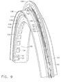
- Figure 9 is an isometric view of the exemplary seal of Figure 2 , in the first position
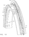
- Figure 10 is an isometric view of the seal of Figure 2 in the second sealing position, similar to the cross-sectional view shown in Figure 3 ;
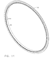
- FIG 11 is an isometric view of the second stator member (102 of Figure 2 );
- Figure 12 is an illustration of a possible alternate flexure member
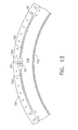
- Figure 13 is a front partial view of another embodiment of a flexure member, similar to that of Figure 6 , useful with the seal assembly;
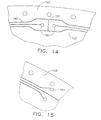
- Figures 14 and 15 are enlarged partial views of the flexure member of Figure 13 ;
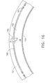
- Figure 16 is a front partial view of another embodiment of a flexure member, similar to that of Figure 6 , useful with the seal assembly;
- Figures 17 and 18 are enlarged partial views of the flexure member of Figure 16 ;
- Figure 19 is a front partial view of another embodiment of a flexure member, similar to that of Figure 6 , useful with the seal assembly;
- Figure 20 is an enlarged partial view of the flexure member of Figure 19 .
- the present invention seal assembly provides a simplified seal with a reduced part count relative to prior art seals thereby simplifying the seal assembly, and reducing the weight of the seal assembly.
- spring assemblies used in related seal assemblies have been replaced by one or more flexure members.
- the flexure member is attached between a non-contact seal slide and a stator.
- secondary seal assemblies of prior art sealing devices have been replaced with a single piston ring seal.
- the single ring seal may be retained within either a fixed or sliding stators.
- the design may incorporate one or more flexure members, the number thereof depending upon the design requirement.
- FIG. 1 is a schematic illustration of an exemplary gas turbine engine 10 including a fan assembly 12 and a core engine 13 including a high pressure compressor 14, and a combustor 16.
- Engine 10 also includes a high pressure turbine 18, a low pressure turbine 20, and a booster 22.
- Fan assembly 12 includes an array of fan blades 24 extending radially outward from a rotor disc 26.
- Engine 10 has an intake side 27 and an exhaust side 29.
- the gas turbine engine is a GE90-115B that is available from General Electric Company, Cincinnati, Ohio.
- Fan assembly 12 and turbine 20 are coupled by a first rotor shaft 31, and compressor 14 and turbine 18 are coupled by a second rotor shaft 33.
- Airflow (not shown in Figure 1 ) from combustor 16 drives turbines 18 and 20, and turbine 20 drives fan assembly 12 by way of shaft 31.
- FIG. 2 is a cross-sectional view of an exemplary seal assembly 100 that may be used within gas turbine engine 10.
- gas turbine engine 10 includes stationary stator member 102 coupled to frame 103 and a rotating member 104.
- rotating member 104 is a rotor that is rotatably coupled within engine 10 to rotate about the axis of rotation 34.
- Frame 103 is a stationary circumferential member positioned around an axis of rotation 34 (not shown in Figure 2 ).
- Frame member 103 includes an attachment flange 108 that extends outwardly away from the frame.
- frame 103 may be comprised of the casing of gas turbine engine 10. As air flows through engine 10, frame 103 is configured to help contain flowpath air.
- Stationary stator member 102 of seal assembly 100 is a stationary member that extends circumferentially around the axis of rotation 34 of gas turbine engine 10.
- the stator is comprised of a base 112 and a flange member 109.
- the base includes a base sealing surface 90 and a stop surface 113.
- the flange and base are perpendicular.
- stationary stator member 102 is fixed to frame 103 by fastener 107.
- the fastener may be comprised of a conventional bolt member or other suitable fastening means.
- the stator flange 109 and frame flange 108 are coupled by the fastener member 107.
- a flexure member 150 which will be disclosed in greater detail below is sandwiched between the head 190 of fastener 107 and a surface 114 of flange 109 of fixed stator 102.
- Seal assembly 100 also is comprised of moveable stator member 110 includes a sealing face 124 and a plurality of sealing teeth 127, 128 that extend outward from a portion of the sealing face 124.
- the stator 110 is movable axially, in direction generally represented by direction arrow 200 in Figure 2 .
- sealing face 124 is substantially parallel to a rotating member surface 125 of rotating member 104. In a first position shown in Figure 2 , the sealing face 124 is located at a distance 123 away from rotating member 104.
- the movable stator 110 of seal assembly 100 is located in the first position when the turbine engine is not in use with no fluid flowing through the engine flowpath.
- Moveable stator member 110 also includes an opening 135 defined therein.
- the opening extends in the axial direction 200 when the movable stator is correctly coupled with flange 108. As shown in Figure 2 , the opening extends through the movable stator surfaces 124 and contact surface 118. When the movable stator is in the first, retracted position, surfaces 118 and 113 are in contact. This contact between movable stator 110 and flange 108 controls the displacement of the stator 110 to the first position.
- openings 135 are oriented substantially perpendicular to rotating member surface 125. As described below in more detail, openings 135 help to prevent contact between the movable member 110, and specifically the plurality of teeth 127, 128; and rotating member 104.
- the movable stator may include any number of openings 135 but for purposes of disclosing the exemplary embodiment, one or more openings 135 may be included in movable stator 110.
- Moveable stator member 110 further includes at least one radially extending opening 134. For purposes of disclosing the exemplary embodiment, a plurality of openings 134 are illustrated. However, any suitable number of radial openings 134 may be provided in stator 110.
- the opening 134 extends through surfaces 119 and 121 of the moveable stator member 110. In the exemplary embodiment, each opening 135 is located adjacent openings 134.
- Moveable stator member 110 also includes yoke 130.
- the yoke extends radially and defines an opening 131 that receives a seal member 132.
- the seal member may be made from any suitable sealing material. As shown in Figures 2 and 3 , when seated in opening 131, a portion of the seal member extends beyond the free end 129 of the yoke. When the movable and fixed stators are coupled as shown in the figures, the end of the seal that extends beyond free end 129 is in sealing contact with contact surface 90 of the fixed stator 102.
- the seal member may be a piston ring seal, for example. Note that in an alternate embodiment, the seal may be supported by stator 102 and engage a sealing surface along the movable member.
- Figure 3 shows the moveable stator member 110 in a second position, also referred to herein as a sealing position.
- a sealing position When air is supplied to the gas turbine flowpath, the pressure of the air causes the movable stator to be displaced in direction 200. As the stator member is displaced, seal 132 remains in contact with sealing surface 90. As the moveable stator moves toward member 104, the magnitude of distance 123 is reduced from its maximum value when the movable stator member is in the first position shown in Figure 2 . As shown in Figure 3 , when the movable stator reaches the end of travel and is in the second position, the sealing face 124 and the rotating member surface 125 are proximate each other.
- Seal assembly 100 also comprises at least one flexure member 150.
- the flexure member is substantially flat. As assembled, one end of flexure member is located proximate the flange member 109. This end is identified as 157 in Figures 2 and 3 . Ends 157 and 152 are joined by biasing member 151. Member 151 is extendible from its retracted length shown in Figure 2 to an extended length as shown in the sealing position of Figure 3 .
- the flexure member 150 comprises a weak spring which flexes out of plane to allow axial translation of the moveable stator member 110 relative to the stationary stator member 102.
- the connection of the flexure member 150 to the moveable stator member 110 is shown in these figures for simplicity as being bolted to the frame 103, but integral with the moveable stator 110. It could alternatively be a separate piece, but such a configuration may increase weight, complexity, and part count.
- Figures 9 and 10 show in isometric view (comparable to the views of Figures 3 and 4 ) the bending of the flexure member (150 series of numbers).
- the flexure member is fixed to stationary stator 108 by bolt connection 107.
- the flexure member also includes a biasing portion 151 that is made integral with the movable stator member 110 at flange 152.
- the flexure member 150 may be integral with moveable stator member 110 and thereby cast with that member 110.
- the flexure member 150 serves as a biasing mechanism for moving the moveable stator member 110.
- the member 150 biases the movable stator member toward the first position of Figure 2 .
- the flexure member 150 returns the movable member to the first non-sealing position when the air flow through the engine is reduced to a minimum level or the engine is shut off.
- the flexure member 150 also controls the translation of movable member 110 to account for relative axial motion between the rotor 104 and the stator 103 during engine operation.
- a flexure member 150 may be preloaded against a stop (surface 113) such that in an un-pressurized state the sealing face 124 is held in an open position, e.g., when the turbine engine 10 has been disengaged into the off position. This condition prevents slide contact of the moveable stator member 110 with the rotor 104 at low or no activation pressures, such contact, when unintended, operating to damage the seal assembly 100 and thus hinder its performance.
- Figure 6 provides an exemplary flexure member 150.
- Flexure member 150 may be made from one or more of known metals in the art including steel, titanium, iron and nickel. As shown, the flexure member 150 includes a central opening 183 that centers the moveable stator member 110 about the engine axis 34, and seams 160 which are openings that extend through the thickness of the flexure member 150 and define beams of material therebetween. The seams 160 permit the flexure member 150 to flex or displace in the desired manner, out of the plane of the Figure. Such movement of the flexure member 150 biases a moveable stator member 110 in the required direction for example to either open or close the seal assembly 100 as directed or required.
- the flexure member includes three seam segments 160, however any number of seams in may be provided.
- the beam count may be altered to achieve desired deflection at seal face 124, as shown in Figure 4 .
- each of the seams comprises two arcuate segments 190, 191 that are joined by a non-arcuate segment 192.
- the non-arcuate portion is oriented radially.
- one of the arcuate segments of each adjacent seam in the clockwise and counterclockwise directions relative to the single seam is located in parallel to the arcuate segments of the single seam, and are separated by a radial distance approximately equal to the length of the radial segment 192.
- the flexure member 150 may be configured to be an annular member as shown in Figure 6 with central opening 183 that receives the moveable stator member 110. Additionally the flexure member may have any suitable seam arrangement. Alternative designs for the seams are illustrated in Figures 7 and 12 .
- the suitable seam arrangement may include adjacent beams being connected together. This connection may be at their proximate ends, such as the connecting segment 162 depicted in Figures 19 and 20 . Connecting adjacent beams may provide various advantages, depending upon material and construction details as well as the operating environment. One potential advantage would be to increase the vibration frequency of the beams, such as to move their vibration frequency out of the range expected to be encountered in normal and/or foreseeable engine operating conditions.
- the seams 160 are openings within each flexure member 150 that have been cut therein into a pattern determined beforehand as suitable to enable the flexure member 150 to flex and therefore bias as required.
- a suitable method for cutting the seams 160 into the flexure member 150 is by electro discharge machining which process is well known by persons of skill in the art. It is noted herein, though, that the methodology for cutting the seams 160 into the flexure member 150 forms no part of the invention herein.
- a flexure member 150 may be cast such that the seams 160 are a by-product of the casting process; i.e., cast such that the openings are part of the process.
- stress relief holes 161 may be added at the ends of the cut-out portions of the seams 160, for example, as shown in Figures 13-18 .
- Figure 7 provides a cut-out of a portion of an alternate configuration of the flexure member 150 of Figure 6 .
- a portion of a seam 160 is shown enlarged.
- each darkened line of the seam 160 represents an opening through the flexure member 150.
- Figure 6 illustrates a possible configuration of a flexure member 150(spring). Taking a sheet of material and cutting the indicated slots in it allows a small force to displace the center of the sheet (feature 152 of Figure 2 ) out of plane from the periphery of the sheet (feature 150 of Figure 2 ).
- Figure 7 shows an alternative configuration of these cuts.
- An infinite number of possible configurations are possible, of which the ones shown in Figures 6 , 7 , and 12 are shown as examples.
- Figures 4 and 5 show an alternate embodiment seal assembly 100 of the present invention.
- Figure 4 shows the movable stator in a first non-sealing position and
- Figure 5 shows the movable stator in a second, sealing position.
- the seal 100 includes flexure members 150 located at opposite ends of an elongate fastener 107.
- the flexure members are separated by spacer 155 that is slidably located on the fastener 107.
- spacer 155 is a useful but not required device between the two flexure members 150.
- the flexure members 150 always act to open the seal (moving the movable stator member 110 to the position shown in Figure 4 ). Air pressures during engine operation overcome the spring forces of the flexure members 150 to move the moveable stator member 110 to the closed position ( Figure 5 ).
- two flexible members 151 are coupled between ends 150 and 152 as described in conjunction with the description of seal assembly 100. Both members 151 extend when the movable stator is displaced in direction 200 to a sealing position. Additionally, seal 132 is in sealing contact with surface 90 of fixed stator base 102.
- cooling air and/or fluids flow through gas turbine engine 10.
- high pressure air flows toward the aft engine end 29.
- a portion of the highly compressed air discharged from high pressure compressor 14 is directed towards seal assembly 100 for use as cooling fluid.
- Seal assembly 100 facilitates substantially controlling fluid flow from a region of higher pressure 137 to a region of lower pressure 140 within gas turbine engine 10.
- the pressure differential between higher pressure region 137 and lower pressure region 140 initiates flow through seal assembly 100.
- the pressures acting on the moveable stator member 110 are such that the pressure forces overcome the spring force of the flexure member 151, and the moveable stator member 110 will translate from the first position (shown in Figures 2 and 4 ) to the second, sealing position ( Figures 3 and 5 ).
- opening 135 is a plurality of feed openings. Openings 135 form a high pressure film or air bearing between surfaces 124 and rotating member surface 125. The air bearing prevents moveable stator member 110 from contacting rotating member 104.
Landscapes
- Engineering & Computer Science (AREA)
- General Engineering & Computer Science (AREA)
- Mechanical Engineering (AREA)
- Gasket Seals (AREA)
- Turbine Rotor Nozzle Sealing (AREA)
Abstract
Description
- The invention generally relates to gas turbine engines and more specifically to seal assemblies used with gas turbine engines.
- Gas turbine engines displace large volumes of pressurized fluid, such as air through the engine fluid flowpath, during operation. Seal assemblies prevent the fluid from leaking undesirably by restricting fluid flow from areas of higher pressure to areas of lower pressure. The seal assemblies may be positioned between engine stationary and rotating members. The seals compensate for transient variations in the gaps between adjacent engine component parts.
- Because of the working environment of the seal assemblies, and/or the operating environment, at least some known seal assemblies may deteriorate over time. If the seals do not provide the required seal, fluid will leak past the seal detrimentally affecting the operation of the engine. Fluid leakage through gas turbine engine seal assemblies may significantly increase fuel consumption and adversely affect engine efficiency. Additionally, fluid leakage may cause damage to other engine components and increase overall engine maintenance costs.
- To facilitate sealing gaps defined between regions of high and low pressure at least some known seal assemblies, such as the seal assembly described in
U.S. Patent No. 5,284,347 , for example, use aspirating air to control leakage. The aspirating air prevents the rotating member from contacting the stationary member to facilitate accommodating transient variations in the gap defined between the rotating and stationary members with little or no deterioration of the seal over the life of the seal assembly. However, because of the number of discrete components comprising such a seal assembly, such seal assemblies may be complex to install in the engine, and the weight of such assemblies will increase engine weight which has a direct negative impact on engine performance. Moreover, because of the number of seal assembly components, the operating efficiency of such seal assemblies may be contingent on the tolerances between the rotating and stationary members. - There is a need to develop a seal assembly that has relatively few parts, effectively prevents leakage of fluid within a turbine engine and does not deteriorate over time.
- A seal assembly comprising a first movable stator member movable between a sealing position and a non-sealing position, a second fixed stator member, the first stator member being movable relative to the second stator member, the seal assembly further comprising at least one flexure member coupled to the second stator member, and at least one biasing member coupled between the at least one flexure and the movable stator for biasing the movable stator to a non-sealing position.
- While the specification concludes with claims particularly pointing out and distinctly claiming the invention, it is believed that the embodiments set forth herein will be better understood from the following description provided by way of example only in conjunction with the accompanying figures, in which like reference numerals identify like elements, and in which:
-
Figure 1 is a schematic illustration of an exemplary gas turbine engine; -
Figure 2 is a cross-sectional view of an exemplary seal assembly that may be used with the gas turbine engine shown inFigure 1 , with a movable sealing member in a first position; -
Figure 3 is a cross-sectional view of the exemplary seal assembly ofFigure 2 with the movable sealing member in a second sealing position; -
Figure 4 is a cross-sectional view of an exemplary seal assembly that may be used with the gas turbine engine shown inFigure 1 , with a movable sealing member in a first open position; -
Figure 5 is a cross-sectional view of the exemplary seal assembly ofFigure 4 with the movable sealing member in a second sealing position; -
Figure 6 is a front view of a flexure member useful with the seal assembly; -
Figure 7 is an alternate embodiment flexure member useful with the seal assembly; -
Figure 8 is a side view of the exemplary seal ofFigure 2 , in a first position; -
Figure 9 is an isometric view of the exemplary seal ofFigure 2 , in the first position; -
Figure 10 is an isometric view of the seal ofFigure 2 in the second sealing position, similar to the cross-sectional view shown inFigure 3 ; -
Figure 11 is an isometric view of the second stator member (102 ofFigure 2 ); -
Figure 12 is an illustration of a possible alternate flexure member; -
Figure 13 is a front partial view of another embodiment of a flexure member, similar to that ofFigure 6 , useful with the seal assembly; -
Figures 14 and 15 are enlarged partial views of the flexure member ofFigure 13 ; -
Figure 16 is a front partial view of another embodiment of a flexure member, similar to that ofFigure 6 , useful with the seal assembly; -
Figures 17 and 18 are enlarged partial views of the flexure member ofFigure 16 ; -
Figure 19 is a front partial view of another embodiment of a flexure member, similar to that ofFigure 6 , useful with the seal assembly; and -
Figure 20 is an enlarged partial view of the flexure member ofFigure 19 . - Although the invention is herein described and illustrated in association with a compressor to turbine interface for a gas turbine engine, it should be understood that the present invention may be used to facilitate controlling leakage of any fluid between any region of generally high pressure and any region of lower pressure.
- Herein, the present invention seal assembly provides a simplified seal with a reduced part count relative to prior art seals thereby simplifying the seal assembly, and reducing the weight of the seal assembly. For example, spring assemblies used in related seal assemblies have been replaced by one or more flexure members. As will be described herein the flexure member is attached between a non-contact seal slide and a stator. Also, secondary seal assemblies of prior art sealing devices have been replaced with a single piston ring seal. The single ring seal may be retained within either a fixed or sliding stators. The design may incorporate one or more flexure members, the number thereof depending upon the design requirement.
-
Figure 1 is a schematic illustration of an exemplarygas turbine engine 10 including afan assembly 12 and acore engine 13 including ahigh pressure compressor 14, and acombustor 16.Engine 10 also includes ahigh pressure turbine 18, alow pressure turbine 20, and abooster 22.Fan assembly 12 includes an array offan blades 24 extending radially outward from arotor disc 26.Engine 10 has anintake side 27 and anexhaust side 29. In one embodiment, the gas turbine engine is a GE90-115B that is available from General Electric Company, Cincinnati, Ohio.Fan assembly 12 andturbine 20 are coupled by afirst rotor shaft 31, andcompressor 14 andturbine 18 are coupled by asecond rotor shaft 33. - During operation, air flows axially through
fan assembly 12, in a direction that is substantially parallel to acentral axis 34 extending throughengine 10, and compressed air is supplied tohigh pressure compressor 14. The highly compressed air is delivered tocombustor 16. Airflow (not shown inFigure 1 ) fromcombustor 16drives turbines turbine 20drives fan assembly 12 by way ofshaft 31. -
Figure 2 is a cross-sectional view of anexemplary seal assembly 100 that may be used withingas turbine engine 10. In the exemplary embodiment,gas turbine engine 10 includesstationary stator member 102 coupled toframe 103 and a rotatingmember 104. In one embodiment, rotatingmember 104 is a rotor that is rotatably coupled withinengine 10 to rotate about the axis ofrotation 34.Frame 103 is a stationary circumferential member positioned around an axis of rotation 34 (not shown inFigure 2 ).Frame member 103 includes anattachment flange 108 that extends outwardly away from the frame. In one embodiment,frame 103 may be comprised of the casing ofgas turbine engine 10. As air flows throughengine 10,frame 103 is configured to help contain flowpath air. -
Stationary stator member 102 ofseal assembly 100 is a stationary member that extends circumferentially around the axis ofrotation 34 ofgas turbine engine 10. The stator is comprised of abase 112 and aflange member 109. The base includes abase sealing surface 90 and astop surface 113. The flange and base are perpendicular. As shown inFigure 2 ,stationary stator member 102 is fixed to frame 103 byfastener 107. The fastener may be comprised of a conventional bolt member or other suitable fastening means. Thestator flange 109 andframe flange 108 are coupled by thefastener member 107. Aflexure member 150, which will be disclosed in greater detail below is sandwiched between thehead 190 offastener 107 and asurface 114 offlange 109 of fixedstator 102. -
Seal assembly 100 also is comprised ofmoveable stator member 110 includes a sealingface 124 and a plurality of sealingteeth face 124. Thestator 110 is movable axially, in direction generally represented bydirection arrow 200 inFigure 2 . In the exemplary embodiment, sealingface 124 is substantially parallel to a rotatingmember surface 125 of rotatingmember 104. In a first position shown inFigure 2 , the sealingface 124 is located at adistance 123 away from rotatingmember 104. Themovable stator 110 ofseal assembly 100 is located in the first position when the turbine engine is not in use with no fluid flowing through the engine flowpath. -
Moveable stator member 110 also includes anopening 135 defined therein. The opening extends in theaxial direction 200 when the movable stator is correctly coupled withflange 108. As shown inFigure 2 , the opening extends through the movable stator surfaces 124 andcontact surface 118. When the movable stator is in the first, retracted position, surfaces 118 and 113 are in contact. This contact betweenmovable stator 110 andflange 108 controls the displacement of thestator 110 to the first position. - In the exemplary embodiment,
openings 135 are oriented substantially perpendicular to rotatingmember surface 125. As described below in more detail,openings 135 help to prevent contact between themovable member 110, and specifically the plurality ofteeth member 104. The movable stator may include any number ofopenings 135 but for purposes of disclosing the exemplary embodiment, one ormore openings 135 may be included inmovable stator 110.Moveable stator member 110 further includes at least one radially extendingopening 134. For purposes of disclosing the exemplary embodiment, a plurality ofopenings 134 are illustrated. However, any suitable number ofradial openings 134 may be provided instator 110. Theopening 134 extends throughsurfaces moveable stator member 110. In the exemplary embodiment, eachopening 135 is locatedadjacent openings 134. -
Moveable stator member 110 also includesyoke 130. The yoke extends radially and defines anopening 131 that receives aseal member 132. The seal member may be made from any suitable sealing material. As shown inFigures 2 and3 , when seated inopening 131, a portion of the seal member extends beyond thefree end 129 of the yoke. When the movable and fixed stators are coupled as shown in the figures, the end of the seal that extends beyondfree end 129 is in sealing contact withcontact surface 90 of the fixedstator 102. The seal member may be a piston ring seal, for example. Note that in an alternate embodiment, the seal may be supported bystator 102 and engage a sealing surface along the movable member. -
Figure 3 shows themoveable stator member 110 in a second position, also referred to herein as a sealing position. When air is supplied to the gas turbine flowpath, the pressure of the air causes the movable stator to be displaced indirection 200. As the stator member is displaced,seal 132 remains in contact with sealingsurface 90. As the moveable stator moves towardmember 104, the magnitude ofdistance 123 is reduced from its maximum value when the movable stator member is in the first position shown inFigure 2 . As shown inFigure 3 , when the movable stator reaches the end of travel and is in the second position, the sealingface 124 and the rotatingmember surface 125 are proximate each other. -
Seal assembly 100 also comprises at least oneflexure member 150. The flexure member is substantially flat. As assembled, one end of flexure member is located proximate theflange member 109. This end is identified as 157 inFigures 2 and3 .Ends member 151.Member 151 is extendible from its retracted length shown inFigure 2 to an extended length as shown in the sealing position ofFigure 3 . - The
flexure member 150 comprises a weak spring which flexes out of plane to allow axial translation of themoveable stator member 110 relative to thestationary stator member 102. The connection of theflexure member 150 to themoveable stator member 110 is shown in these figures for simplicity as being bolted to theframe 103, but integral with themoveable stator 110. It could alternatively be a separate piece, but such a configuration may increase weight, complexity, and part count. -
Figures 9 and10 show in isometric view (comparable to the views ofFigures 3 and4 ) the bending of the flexure member (150 series of numbers). The flexure member is fixed tostationary stator 108 bybolt connection 107. The flexure member also includes a biasingportion 151 that is made integral with themovable stator member 110 atflange 152. Theflexure member 150 may be integral withmoveable stator member 110 and thereby cast with thatmember 110. - The
flexure member 150 serves as a biasing mechanism for moving themoveable stator member 110. Themember 150 biases the movable stator member toward the first position ofFigure 2 . Theflexure member 150 returns the movable member to the first non-sealing position when the air flow through the engine is reduced to a minimum level or the engine is shut off. Theflexure member 150 also controls the translation ofmovable member 110 to account for relative axial motion between therotor 104 and thestator 103 during engine operation. Aflexure member 150 may be preloaded against a stop (surface 113) such that in an un-pressurized state the sealingface 124 is held in an open position, e.g., when theturbine engine 10 has been disengaged into the off position. This condition prevents slide contact of themoveable stator member 110 with therotor 104 at low or no activation pressures, such contact, when unintended, operating to damage theseal assembly 100 and thus hinder its performance. -
Figure 6 provides anexemplary flexure member 150.Flexure member 150 may be made from one or more of known metals in the art including steel, titanium, iron and nickel. As shown, theflexure member 150 includes acentral opening 183 that centers themoveable stator member 110 about theengine axis 34, andseams 160 which are openings that extend through the thickness of theflexure member 150 and define beams of material therebetween. Theseams 160 permit theflexure member 150 to flex or displace in the desired manner, out of the plane of the Figure. Such movement of theflexure member 150 biases amoveable stator member 110 in the required direction for example to either open or close theseal assembly 100 as directed or required. - As shown in
Figure 6 , the flexure member includes threeseam segments 160, however any number of seams in may be provided. The beam count may be altered to achieve desired deflection atseal face 124, as shown inFigure 4 . In the present embodiment, each of the seams comprises twoarcuate segments non-arcuate segment 192. The non-arcuate portion is oriented radially. As shown inFigure 6 , for a single seam, one of the arcuate segments of each adjacent seam in the clockwise and counterclockwise directions relative to the single seam, is located in parallel to the arcuate segments of the single seam, and are separated by a radial distance approximately equal to the length of theradial segment 192. Theflexure member 150 may be configured to be an annular member as shown inFigure 6 withcentral opening 183 that receives themoveable stator member 110. Additionally the flexure member may have any suitable seam arrangement. Alternative designs for the seams are illustrated inFigures 7 and12 . The suitable seam arrangement may include adjacent beams being connected together. This connection may be at their proximate ends, such as the connectingsegment 162 depicted inFigures 19 and 20 . Connecting adjacent beams may provide various advantages, depending upon material and construction details as well as the operating environment. One potential advantage would be to increase the vibration frequency of the beams, such as to move their vibration frequency out of the range expected to be encountered in normal and/or foreseeable engine operating conditions. - The
seams 160 are openings within eachflexure member 150 that have been cut therein into a pattern determined beforehand as suitable to enable theflexure member 150 to flex and therefore bias as required. A suitable method for cutting theseams 160 into theflexure member 150 is by electro discharge machining which process is well known by persons of skill in the art. It is noted herein, though, that the methodology for cutting theseams 160 into theflexure member 150 forms no part of the invention herein. In another embodiment herein, aflexure member 150 may be cast such that theseams 160 are a by-product of the casting process; i.e., cast such that the openings are part of the process. Additionally,stress relief holes 161 may be added at the ends of the cut-out portions of theseams 160, for example, as shown inFigures 13-18 . -
Figure 7 provides a cut-out of a portion of an alternate configuration of theflexure member 150 ofFigure 6 . In particular, a portion of aseam 160 is shown enlarged. Herein, each darkened line of theseam 160 represents an opening through theflexure member 150.Figure 6 illustrates a possible configuration of a flexure member 150(spring). Taking a sheet of material and cutting the indicated slots in it allows a small force to displace the center of the sheet (feature 152 ofFigure 2 ) out of plane from the periphery of the sheet (feature 150 ofFigure 2 ).Figure 7 shows an alternative configuration of these cuts. An infinite number of possible configurations are possible, of which the ones shown inFigures 6 ,7 , and12 are shown as examples. -
Figures 4 and5 show an alternateembodiment seal assembly 100 of the present invention.Figure 4 shows the movable stator in a first non-sealing position andFigure 5 shows the movable stator in a second, sealing position. Theseal 100 includesflexure members 150 located at opposite ends of anelongate fastener 107. The flexure members are separated byspacer 155 that is slidably located on thefastener 107. In this alternate configuration,flexure members 150 are positioned in a parallel orientation and are held apart by aspacer 155.Spacer 155 is a useful but not required device between the twoflexure members 150. - The
flexure members 150 always act to open the seal (moving themovable stator member 110 to the position shown inFigure 4 ). Air pressures during engine operation overcome the spring forces of theflexure members 150 to move themoveable stator member 110 to the closed position (Figure 5 ). - As shown in
Figures 4 and5 , twoflexible members 151 are coupled between ends 150 and 152 as described in conjunction with the description ofseal assembly 100. Bothmembers 151 extend when the movable stator is displaced indirection 200 to a sealing position. Additionally,seal 132 is in sealing contact withsurface 90 of fixedstator base 102. - During operation, cooling air and/or fluids flow through
gas turbine engine 10. Whenengine 10 is in operation, high pressure air flows toward theaft engine end 29. A portion of the highly compressed air discharged fromhigh pressure compressor 14 is directed towardsseal assembly 100 for use as cooling fluid.Seal assembly 100 facilitates substantially controlling fluid flow from a region ofhigher pressure 137 to a region oflower pressure 140 withingas turbine engine 10. The pressure differential betweenhigher pressure region 137 andlower pressure region 140 initiates flow throughseal assembly 100. The pressures acting on themoveable stator member 110 are such that the pressure forces overcome the spring force of theflexure member 151, and themoveable stator member 110 will translate from the first position (shown inFigures 2 and4 ) to the second, sealing position (Figures 3 and5 ). - Additionally, during operation, a portion of the high pressure air flows through
openings 135. In the exemplary embodiment, opening 135 is a plurality of feed openings.Openings 135 form a high pressure film or air bearing betweensurfaces 124 and rotatingmember surface 125. The air bearing preventsmoveable stator member 110 from contacting rotatingmember 104. - After air flows through
opening 135, the air exits to the region oflower pressure 140. Also, a portion of air may leakpast seal teeth past seal teeth opening 135 and flows radially outward, flows throughradial openings 134 to the region oflower pressure 140. - While the invention has been described in terms of various specific embodiments, those skilled in the art will recognize that the invention can be practiced with modification within the spirit and scope of the claims.
Claims (9)
- A seal assembly (100) comprising:a first movable stator member (110) movable between a sealing position and a non-sealing position, a second fixed stator member (102), the first stator member (110) being movable relative to the second stator member (102), the seal assembly (100) further comprising at least one flexure member (150) coupled to the second stator member (102), and at least one biasing member (151) coupled between the at least one flexure member (150) and the movable stator (110) for biasing the movable stator (110) to a non-sealing position.
- The seal assembly (100) of Claim 1, having at least two flexure members (150) and two biasing members (151), each biasing member (151) coupled to a flexure member (150).
- The seal assembly (100) as claimed in Claim 1 or Claim 2, the second stator (102) comprising a base (112) and a surface (114) along the base (112), the first stator (110) comprising a sealing member (124) that sealingly engages the contact surface (118) of said base (112).
- The seal assembly (100) of any one of the preceding Claims, wherein the first stator (110) comprises a yoke (130), said member (110) being located in said yoke (130).
- The seal assembly (100) as claimed in any one of the preceding Claims, wherein the flexure member (150) is supported on a fastener member (107).
- The seal assembly (100) of any one of the preceding Claims, wherein said flexure member (150) includes at least one seam (160) which permits said flexure member (150) to flex out of plane.
- The seal assembly (100) of Claim 6, wherein said seam (160) comprises an opening through said flexure member (150).
- The seal assembly (100) of Claim 7, wherein said flexure member (150) includes a plurality of seams (160), said seams (160) defining at least one beam therebetween, said beam being connected to another beam at their proximate ends (152,157).
- The seal assembly (100) of Claim 8, wherein said flexure member (150) includes at least one stress relief hole (161) at the end of a seam (160).
Applications Claiming Priority (2)
| Application Number | Priority Date | Filing Date | Title |
|---|---|---|---|
| US11/830,236 US20090033037A1 (en) | 2007-07-30 | 2007-07-30 | Seal assembly |
| US12/171,418 US20110229311A1 (en) | 2007-07-30 | 2008-07-11 | Seal assembly |
Publications (1)
| Publication Number | Publication Date |
|---|---|
| EP2020542A1 true EP2020542A1 (en) | 2009-02-04 |
Family
ID=39930622
Family Applications (1)
| Application Number | Title | Priority Date | Filing Date |
|---|---|---|---|
| EP08161286A Withdrawn EP2020542A1 (en) | 2007-07-30 | 2008-07-28 | Seal assembly |
Country Status (4)
| Country | Link |
|---|---|
| US (1) | US20110229311A1 (en) |
| EP (1) | EP2020542A1 (en) |
| JP (1) | JP2009052545A (en) |
| CA (1) | CA2638390A1 (en) |
Cited By (4)
| Publication number | Priority date | Publication date | Assignee | Title |
|---|---|---|---|---|
| US10359117B2 (en) | 2017-03-06 | 2019-07-23 | General Electric Company | Aspirating face seal with non-coiled retraction springs |
| US10711629B2 (en) | 2017-09-20 | 2020-07-14 | Generl Electric Company | Method of clearance control for an interdigitated turbine engine |
| US11028718B2 (en) | 2017-09-20 | 2021-06-08 | General Electric Company | Seal assembly for counter rotating turbine assembly |
| US11428160B2 (en) | 2020-12-31 | 2022-08-30 | General Electric Company | Gas turbine engine with interdigitated turbine and gear assembly |
Families Citing this family (5)
| Publication number | Priority date | Publication date | Assignee | Title |
|---|---|---|---|---|
| US9291067B2 (en) * | 2013-11-11 | 2016-03-22 | General Electric Company | Rotary machine aspirating seal assembly and method of assembling the same |
| US10329938B2 (en) * | 2017-05-31 | 2019-06-25 | General Electric Company | Aspirating face seal starter tooth abradable pocket |
| FR3085180B1 (en) * | 2018-08-24 | 2020-11-27 | Safran Aircraft Engines | BLADE ASSEMBLY FOR TURBINE TURBINE STATOR INCLUDING INCLINED SEALING RIBS |
| CN113915028A (en) * | 2021-10-09 | 2022-01-11 | 中国航发贵阳发动机设计研究所 | A hopper mixer with plates and hopper holes |
| US12366172B1 (en) * | 2024-03-01 | 2025-07-22 | General Electric Company | Seal assembly for a rotary machine having a flexible joint |
Citations (5)
| Publication number | Priority date | Publication date | Assignee | Title |
|---|---|---|---|---|
| US5284347A (en) | 1991-03-25 | 1994-02-08 | General Electric Company | Gas bearing sealing means |
| EP0745793A1 (en) * | 1995-05-04 | 1996-12-04 | EG&G SEALOL, INC. | Face seal device having high angular compliance |
| EP0828064A2 (en) * | 1996-09-09 | 1998-03-11 | Calsonic Corporation | Circular plate spring |
| EP1348834A2 (en) * | 2002-03-26 | 2003-10-01 | General Electric Company | Aspirating face seal with axially biasing one-piece annular spring |
| FR2867244A1 (en) * | 2004-03-05 | 2005-09-09 | Attax | Spring e.g. spiral spring, has link arms, each with one end connected to inner edge of outer support plate and other end to outer edge of inner support plate, where ends are moved with respect to each other around spring axis |
Family Cites Families (14)
| Publication number | Priority date | Publication date | Assignee | Title |
|---|---|---|---|---|
| US1323188A (en) * | 1919-11-25 | Frank hxjmphbis | ||
| US3107766A (en) * | 1961-05-03 | 1963-10-22 | Gen Motors Corp | Friction engaging devices having a lever spring |
| JPS5712161Y2 (en) * | 1975-02-17 | 1982-03-10 | ||
| JPS5237741Y2 (en) * | 1975-04-04 | 1977-08-27 | ||
| JPS6128139Y2 (en) * | 1980-03-03 | 1986-08-21 | ||
| US4687346A (en) * | 1986-09-02 | 1987-08-18 | United Technologies Corporation | Low profile bearing support structure |
| US5205547A (en) * | 1991-01-30 | 1993-04-27 | Mattingly William R | Wave spring having uniformly positioned projections and predetermined spring |
| CA2076120A1 (en) * | 1991-09-11 | 1993-03-12 | Adam Nelson Pope | System and method for improved engine cooling |
| US6145840A (en) * | 1995-06-02 | 2000-11-14 | Stein Seal Company | Radial flow seals for rotating shafts which deliberately induce turbulent flow along the seal gap |
| US6676369B2 (en) * | 2002-03-26 | 2004-01-13 | General Electric Company | Aspirating face seal with axially extending seal teeth |
| DE10214276A1 (en) * | 2002-03-28 | 2003-10-16 | Bosch Gmbh Robert | Machine, especially generator |
| US6719296B2 (en) * | 2002-07-12 | 2004-04-13 | General Electric Company | Seal for a rotating member |
| DE102004041074A1 (en) * | 2004-08-25 | 2006-03-02 | Robert Bosch Gmbh | Electric machine with an axial spring element |
| CA2591249A1 (en) * | 2006-06-10 | 2007-12-10 | General Electric Company | Aspirating labyrinth seal |
-
2008
- 2008-07-11 US US12/171,418 patent/US20110229311A1/en not_active Abandoned
- 2008-07-28 EP EP08161286A patent/EP2020542A1/en not_active Withdrawn
- 2008-07-29 JP JP2008194230A patent/JP2009052545A/en active Pending
- 2008-07-30 CA CA002638390A patent/CA2638390A1/en not_active Abandoned
Patent Citations (5)
| Publication number | Priority date | Publication date | Assignee | Title |
|---|---|---|---|---|
| US5284347A (en) | 1991-03-25 | 1994-02-08 | General Electric Company | Gas bearing sealing means |
| EP0745793A1 (en) * | 1995-05-04 | 1996-12-04 | EG&G SEALOL, INC. | Face seal device having high angular compliance |
| EP0828064A2 (en) * | 1996-09-09 | 1998-03-11 | Calsonic Corporation | Circular plate spring |
| EP1348834A2 (en) * | 2002-03-26 | 2003-10-01 | General Electric Company | Aspirating face seal with axially biasing one-piece annular spring |
| FR2867244A1 (en) * | 2004-03-05 | 2005-09-09 | Attax | Spring e.g. spiral spring, has link arms, each with one end connected to inner edge of outer support plate and other end to outer edge of inner support plate, where ends are moved with respect to each other around spring axis |
Cited By (4)
| Publication number | Priority date | Publication date | Assignee | Title |
|---|---|---|---|---|
| US10359117B2 (en) | 2017-03-06 | 2019-07-23 | General Electric Company | Aspirating face seal with non-coiled retraction springs |
| US10711629B2 (en) | 2017-09-20 | 2020-07-14 | Generl Electric Company | Method of clearance control for an interdigitated turbine engine |
| US11028718B2 (en) | 2017-09-20 | 2021-06-08 | General Electric Company | Seal assembly for counter rotating turbine assembly |
| US11428160B2 (en) | 2020-12-31 | 2022-08-30 | General Electric Company | Gas turbine engine with interdigitated turbine and gear assembly |
Also Published As
| Publication number | Publication date |
|---|---|
| US20110229311A1 (en) | 2011-09-22 |
| CA2638390A1 (en) | 2009-01-30 |
| JP2009052545A (en) | 2009-03-12 |
Similar Documents
| Publication | Publication Date | Title |
|---|---|---|
| US20090033037A1 (en) | Seal assembly | |
| EP2020542A1 (en) | Seal assembly | |
| EP1852573A2 (en) | Sealing assembly for gas turbine engines | |
| US6758477B2 (en) | Aspirating face seal with axially biasing one piece annular spring | |
| US6676369B2 (en) | Aspirating face seal with axially extending seal teeth | |
| EP2546469B1 (en) | Blade outer air seal assembly | |
| US8540479B2 (en) | Active retractable seal for turbo machinery and related method | |
| EP2357385B1 (en) | Reverse flow tolerant spring activated brush seal | |
| CN108533334B (en) | Turbine suction face seal assemblies | |
| JP4005020B2 (en) | Sealing method and apparatus for gas turbine shaft | |
| CN115434814A (en) | Turbine engine with rotor seal assembly | |
| EP2955330A2 (en) | Cooling systems for gas turbine engine components | |
| US6932567B2 (en) | Method and apparatus for controlling fluid leakage through gas turbine engines | |
| US7654791B2 (en) | Apparatus and method for controlling a blade tip clearance for a compressor | |
| EP3358149B1 (en) | Bleed valve with neutral or closing bias | |
| EP2233700B1 (en) | Self balancing face seals and gas turbine engine systems involving such seals | |
| JP4370232B2 (en) | Fluid machine with fluid seal mechanism | |
| EP3841286B1 (en) | Secondary seal in a non-contact seal assembly | |
| US11891898B2 (en) | Seal assemblies for turbine engines | |
| EP3002418B1 (en) | Actuation apparatus for an air modulating system of a gas turbine | |
| CN115680897B (en) | Turbine engine with floating seal assembly | |
| EP3960991A1 (en) | Combustor seal system and corresponding method |
Legal Events
| Date | Code | Title | Description |
|---|---|---|---|
| PUAI | Public reference made under article 153(3) epc to a published international application that has entered the european phase |
Free format text: ORIGINAL CODE: 0009012 |
|
| AK | Designated contracting states |
Kind code of ref document: A1 Designated state(s): AT BE BG CH CY CZ DE DK EE ES FI FR GB GR HR HU IE IS IT LI LT LU LV MC MT NL NO PL PT RO SE SI SK TR |
|
| AX | Request for extension of the european patent |
Extension state: AL BA MK RS |
|
| RIN1 | Information on inventor provided before grant (corrected) |
Inventor name: ANGA, PRATHAP Inventor name: IPPILI, SAI RAJU Inventor name: KHANDEPARKER, MAHESH Inventor name: CRUDGINGTON, PETER Inventor name: HERRON, WILLIAM LEE Inventor name: ALBERS, JOSEPH Inventor name: VARANASI, KRIPA |
|
| 17P | Request for examination filed |
Effective date: 20090804 |
|
| 17Q | First examination report despatched |
Effective date: 20090828 |
|
| AKX | Designation fees paid |
Designated state(s): BE DE FR GB |
|
| STAA | Information on the status of an ep patent application or granted ep patent |
Free format text: STATUS: THE APPLICATION IS DEEMED TO BE WITHDRAWN |
|
| 18D | Application deemed to be withdrawn |
Effective date: 20140201 |