EP2020370A1 - Straddle-type vehicle - Google Patents
Straddle-type vehicle Download PDFInfo
- Publication number
- EP2020370A1 EP2020370A1 EP08252514A EP08252514A EP2020370A1 EP 2020370 A1 EP2020370 A1 EP 2020370A1 EP 08252514 A EP08252514 A EP 08252514A EP 08252514 A EP08252514 A EP 08252514A EP 2020370 A1 EP2020370 A1 EP 2020370A1
- Authority
- EP
- European Patent Office
- Prior art keywords
- reflector
- headlight
- cowl
- vehicle
- flasher lamp
- Prior art date
- Legal status (The legal status is an assumption and is not a legal conclusion. Google has not performed a legal analysis and makes no representation as to the accuracy of the status listed.)
- Granted
Links
Images


Classifications
-
- B—PERFORMING OPERATIONS; TRANSPORTING
- B60—VEHICLES IN GENERAL
- B60Q—ARRANGEMENT OF SIGNALLING OR LIGHTING DEVICES, THE MOUNTING OR SUPPORTING THEREOF OR CIRCUITS THEREFOR, FOR VEHICLES IN GENERAL
- B60Q1/00—Arrangement of optical signalling or lighting devices, the mounting or supporting thereof or circuits therefor
- B60Q1/0029—Spatial arrangement
- B60Q1/0041—Spatial arrangement of several lamps in relation to each other
-
- B—PERFORMING OPERATIONS; TRANSPORTING
- B62—LAND VEHICLES FOR TRAVELLING OTHERWISE THAN ON RAILS
- B62J—CYCLE SADDLES OR SEATS; AUXILIARY DEVICES OR ACCESSORIES SPECIALLY ADAPTED TO CYCLES AND NOT OTHERWISE PROVIDED FOR, e.g. ARTICLE CARRIERS OR CYCLE PROTECTORS
- B62J6/00—Arrangement of optical signalling or lighting devices on cycles; Mounting or supporting thereof; Circuits therefor
- B62J6/02—Headlights
- B62J6/022—Headlights specially adapted for motorcycles or the like
- B62J6/026—Headlights specially adapted for motorcycles or the like characterised by the structure, e.g. casings
Definitions
- the present invention relates to a straddle-type vehicle, in which a headlight and a flasher lamp are provided on a body cowl.
- a method of providing a body cowl forwardly of a steering head pipe is widely used in straddle-type vehicles such as motorcycles, etc.
- a body cowl is provided with a headlight and a flasher lamp.
- a headlight includes a headlight bulb and a reflector, by which light irradiated from the headlight bulb is reflected forward.
- a front portion of the headlight is covered by a headlight lens mounted along an outer periphery of the reflector.
- straddle-type vehicles provided with a body cowl
- a construction is known in which a headlight is provided centrally of the body cowl and a pair ot flasher lamps are provided on right and left ends.
- Such an arrangement is disclosed in, for example, JP-A-2005-41476 . In this manner, by separating the flasher lamps from the headlight, it is possible to suppress a decrease in visibility of the flasher lamps when the headlight is illuminated.
- the body cowl described above involves the following problem. That is, in order to ensure the visibility of the flasher lamp, it is necessary to separate the flasher lamps from the headlight, thus causing a problem that it is difficult to make a vehicle width small.
- a flasher lamp having a large luminance it is conceivable to use a flasher lamp having a large luminance to thereby make the flasher lamp close to a headlight while ensuring the visibility of the flasher lamp.
- a flasher lamp having a large luminance is large in power consumption and so not preferable.
- the invention has been thought of in view of the situation and has its object to provide a straddle-type vehicle having a small vehicle width while ensuring visibility of a flasher lamp.
- a straddle-type vehicle comprising:
- the reflector may include a reflector planar portion formed rearward of the reflector straight portion to be made planar.
- the reflector may further include a reflector outer wall formed outwardly of the reflector from the reflector straight portion as viewed from the front of a vehicle.
- the reflector outer wall may be extended rearward from the reflector straight portion.
- an outer periphery of the flasher lamp may include a flasher lamp straight portion formed straight.
- the reflector straight portion and the flasher lamp straight portion may be arranged substantially in parallel to each other.
- the flasher lamp straight portion may be positioned toward the headlight lens on the outer periphery of the flasher lamp.
- the body cowl may include an upper cowl portion, on which the headlight unit is provided, a lower cowl portion, on which the flasher lamp is provided, and a constricted portion formed at a boundary of the upper cowl portion and the lower cowl portion.
- the upper cowl portion may be smaller in width than the lower cowl portion.
- the outer periphery of the reflector may further include a first curved portion and a second curved portion, which are formed curvilinearly.
- One end of the reflector straight portion may be contiguous to the first curved portion.
- the other end of the reflector straight portion may be contiguous to the second curved portion.
- a vehicle comprises a steering head pipe, a body cowl arranged forwardly of the steering head pipe, a headlight unit provided centrally of the body cowl, and a flasher lamp arranged on a side end portion of the body cowl, and that the headlight unit includes a headlight and a headlight lens, which covers the front of the headlight, and the headlight comprises a headlight bulb and a reflector, by which light irradiated from the headlight bulb is reflected forward.
- an outer periphery of the reflector is provided inwardly of an outer periphery of the headlight lens
- the flasher lamp is provided outwardly of the outer periphery of the headlight lens
- the outer periphery of the reflector includes a reflector straight portion formed in a straight manner, and the reflector straight portion is positioned between the headlight bulb and the flasher lamp.
- the outer periphery of the reflector is provided inwardly of an outer periphery of the headlight lens, it is possible to make the flasher lamp close to the headlight lens while ensuring the size of the headlight lens. Consequently, it is possible to decrease the straddle-ride type vehicle in vehicle width.
- the reflector may include a reflector planar portion formed rearward of the reflector straight portion to be made planar.
- the flasher lamp is improved in visibility, it is possible to make the flasher lamps, which are provided at both ends of the body cowl, close to the headlight unit provided centrally of the body cowl. Consequently, it is possible to decrease the straddle-ride type vehicle in vehicle width also in the case where a headlight unit and a flasher lamp are provided integrally on a body cowl.
- the reflector planar portion by forming the reflector planar portion, light irradiated from the headlight bulb can be focused forward as compared with the case where a whole inner wall surface of a reflector is defined by a curved surface.
- the reflector may further include a reflector outer wall formed outwardly of the reflector from the reflector straight portion as viewed from the front of a vehicle, and the reflector outer wall may be extended rearward from the reflector straight portion.
- an outer periphery of the flasher lamp may include a flasher lamp straight portion formed straight.
- the reflector straight portion and the flasher lamp straight portion may be arranged substantially parallel to each other, and the flasher lamp straight portion may be positioned toward the headlight lens on the outer periphery of the flasher lamp.
- the body cowl may include an upper cowl portion, on which the headlight unit is provided, a lower cowl portion, on which the flasher lamp is provided, and a constricted portion formed at a boundary of the upper cowl portion and the lower cowl portion.
- the upper cowl portion may be smaller in width than the lower cowl portion.
- the outer periphery of the reflector may further include a first curved portion and a second curved portion, which are formed curvilinearly.
- One end of the reflector straight portion may be contiguous to the first curved portion and the other end of the reflector straight portion may be contiguous to the second curved portion.
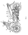
- Fig. 1 is a left side view showing a motorcycle 1 being a straddle-type vehicle according to the embodiment.
- the motorcycle 1 comprises a so-called underbone-type motorcycle, of which a body frame 40 is arranged under as compared with a conventional straddle-type motorcycle.
- the motorcycle 1 comprises a front wheel 20 and a rear wheel 80 and a driving force generated by an engine 50 drives the rear wheel 80.
- the motorcycle 1 is covered by a plurality of body covers. Specifically, the motorcycle 1 is covered by a body cowl 30, a leg shield 36, an undercover 37, a seat undercover 38, and a side cover 39.
- the body cowl 30 is arranged forwardly of a steering head pipe 41.
- the leg shield 36 is arranged forwardly of rider's legs with a rider seated on a seat 70.
- the leg shield 36 is fixed to a downtube 42 extending downward from the steering head pipe 41.
- the body cowl 30 is mounted to the leg shield 36.
- a headlight unit 10 Arranged on the body cowl 30 are a headlight unit 10 and flasher lamps 100L, 100R.
- the flasher lamp 100R is not shown in Fig. 1 (see Fig. 2 ).
- a handle cover 22 is arranged above the body cowl 30 to cover the front of a handle 21.
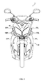
- Fig. 2 is a front view showing the motorcycle 1.
- the headlight unit 10 is provided centrally of the body cowl 30 in a vehicle width direction.
- the flasher lamps 100L, 100R are provided at both sides of the body cowl 30 in the vehicle width direction.
- the body cowl 30 is formed by an upper cowl portion 31 and lower cowl portions 32L, 32R. Constricted portions 33L, 33R are formed at boundaries between the upper cowl portion 31 and the lower cowl portions 32L, 32R. The constricted portions 33L, 33R are formed to be shaped to have a predetermined width in the vehicle width direction. The constricted portions 33L, 33R are extended rearward and upward from a front end of the body cowl 30.
- the upper cowl portion 31 is arranged above the front wheel 20.
- the upper cowl portion 31 is larger in width than the front wheel 20 and extended outwardly of the front wheel 20 in the vehicle width direction.
- the lower cowl portions 32L, 32R are contiguous to the upper cowl portion 31 with the constricted portions 33L, 33R therebetween. Accordingly, the upper cowl portion 31 is smaller in width than the lower cowl portions 32L, 32R. That is, the upper cowl portion 31 is enlarged by the constricted portions 33L, 33R in the vehicle width direction to be contiguous to the lower cowl portions 32L, 32R.
- the lower cowl portion 32L is arranged on a left side of the motorcycle 1 and the lower cowl portion 32R is arranged on a right side of the motorcycle 1. Accordingly, the lower cowl portions 32L, 32R are leg-shaped to extend downward from the upper cowl portion 31.
- the headlight unit 10 is provided centrally of the upper cowl portion 31 in the vehicle width direction.
- the flasher lamps 100L, 100R are provided at both outer ends or sides of the lower cowl portions 32L, 32R in the vehicle width direction.
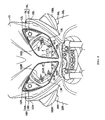
- Fig. 3 is a front view showing, in enlarged scale, the region of boundaries between the upper cowl portion 31 and the lower cowl portions 32L, 32R.
- the headlight unit 10 comprises a headlight 11, headlight lenses 12L, 12R, reflector outer walls 13L, 13R, and position lamps 14L, 14R.
- the headlight 11 comprises a headlight bulb 11a and a reflector 11b.
- the reflector 11b reflects that light, which is irradiated from the headlight bulb 11a, forward. Accordingly, the reflector 11b is formed by using a material having a high reflection effect. A bulb hole, into which the headlight bulb 11a is fitted, is formed centrally of the reflector 11b. The headlight bulb 11a lights up with a predetermined quantity of light or light intensity. The front of the headlight bulb 11a is covered by a part of the upper cowl portion 31.
- the headlight lenses 12L, 12R are arranged to cover the front of the headlight 11.
- the headlight lenses 12L, 12R are arranged symmetrically on the left and right of that portion of the upper cowl portion 31, which covers the front of the headlight bulb 11a.
- the headlight lenses 12L, 12R comprise a colorless, transparent lens.
- an outer periphery of the reflector 11b is formed inwardly of outer peripheries of the headlight lenses 12L, 12R in the vehicle width direction. Also, an outer periphery of the reflector 11b includes reflector straight portions 101L, 101R formed straight, reflector first curved portions 102L, 102R, and reflector second curved portions 103L, 103R.
- An upper end of the reflector straight portion 101L is contiguous to the reflector first curved portion 102L and a lower end of the reflector straight portion 101L is contiguous to the reflector second curved portion 103L.
- the reflector 11b includes reflector planar portions 104L, 104R formed rearward of the reflector straight portions 101L, 101R, respectively, to be made planar. Accordingly, the reflector planar portions 104L, 104R define a part of an inner wall of the reflector 11b.
- the reflector outer walls 13L, 13R are formed outwardly of the reflector 11b from the reflector straight portions 101L, 101R as viewed from the front of a vehicle.
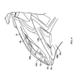
- Fig. 4 is a left side view showing, in enlarged scale, the region of a boundary between the upper cowl portion 31 and the lower cowl portion 32L. As shown in the figure, the reflector outer wall 13L is extended rearward from the reflector straight portion 101L.
- the reflector outer walls 13L, 13R are formed rearward and outward from the reflector straight portions 101L, 101R.
- the reflector outer walls 13L, 13R are formed integral with the reflector 11b by the use of the same material as that of the reflector 11b.
- the position lamps 14L, 14R comprise position lamp reflectors 15L, 15R and position lamp bulbs 16L, 16R. As shown in Fig. 3 , the position lamp reflectors 15L, 15R, respectively, are formed to be triangular-shaped between outer peripheries of the headlight lenses 12L, 12R and an outer periphery of the reflector 11b.
- the flasher lamps 100L, 100R comprise a lens portion and a flasher bulb (only an outward appearance of the lens portion is depicted).
- the lens portion comprises a colorless lens.
- the flasher lamps flash in an amber color (or an orange color) at predetermined intervals.
- the flasher lamps 100L, 100R are fitted into flasher lamp receiving recesses 34L, 34R formed on the body cowl 30 (the lower cowl portions 32L, 32R).
- the flasher lamp receiving recesses 34L, 34R are formed symmetrically at both ends of the lower cowl portions 32L, 32R.
- the flasher lamps 100L, 100R are formed outwardly of the outer peripheries of the headlight lenses 12L, 12R in the vehicle width direction as shown in Fig. 3 .
- the flasher lamps 100L, 100R are formed convexly outwardly in the vehicle width direction. Also, the flasher lamp 100L is larger in size in a vertical direction than in a longitudinal direction. That is, the flasher lamp 100L is crosswise lengthy in shape in a state of being mounted to the lower cowl portion 32L. Also, as shown in the figure, the flasher lamp 100L is similar in shape to a cross section of a blade (airfoil) as viewed laterally of a vehicle body.
- an outer periphery of the flasher lamp 100L (specifically, the lens portion) includes a flasher lamp straight portion 110L formed in a straight manner as shown in Fig. 4 .
- the flasher lamp straight portion 110L is formed to be directed rearward and upward as viewed laterally of a vehicle body.
- the flasher lamp straight portion 110L is positioned toward the headlight lens 12L on the outer periphery of the flasher lamp 100L.
- Fig. 5 is a front view showing, in enlarged scale, the left side of the reflector 11b and the region of the flasher lamp 100L.
- the reflector straight portion 101L is positioned between the headlight bulb 11a and the flasher lamp 100L.
- the reflector straight portion 101L is provided inside the outer periphery of the headlight lens 12L and the flasher lamp straight portion 110L is provided outside the outer periphery of the headlight lens 12L.
- a reference line ⁇ , indicative of a direction, in which the reflector straight portion 101L is extended, and a reference line ⁇ indicative of a direction, in which the flasher lamp straight portion 110L is extended are substantially parallel to each other as viewed from the front of a vehicle. That is, the reflector straight portion 101L and the flasher lamp straight portion 110L are formed substantially parallel to each other as viewed from the front of a vehicle.
- the reflector straight portion 101L and the flasher lamp straight portion 110L are not substantially parallel to each other as viewed laterally of a vehicle body (see Fig. 3 ) and as viewed in plan view of a vehicle body (see Fig. 6 ).
- the outer periphery of the reflector 11b is provided inside the outer peripheries of the headlight lenses 12L, 12R as viewed from the front of a vehicle.
- the flasher lamps 100L, 100R are provided outside the outer peripheries of the headlight lenses 12L, 12R.
- the outer periphery of the reflector 11b includes reflector straight portions 101L, 101R formed in a straight manner.
- the outer periphery of the reflector 11b is provided inside the outer peripheries of the headlight lenses 12L, 12R, so that it is possible to make the flasher lamps 100L, 100R close to the headlight lenses 12L, 12R while ensuring sizes of the headlight lenses 12L, 12R. Consequently, it is possible to decrease the motorcycle 1 in vehicle width.
- the reflector straight portions 101L, 101R are positioned between the headlight bulb 11a and the flasher lamps 100L, 100R.
- the reflector 11b includes the reflector planar portions 104L, 104R formed rearward of the reflector straight portions 101L, 101R to be made planar.
- the flasher lamps are improved in visibility, it is possible to make the flasher lamps 100L, 100R, which are provided at both ends of the body cowl 30, close to the headlight unit 10 provided centrally of the body cowl 30. Consequently, it is possible to decrease the motorcycle 1 in vehicle width also in the case where the headlight unit 10 and the flasher lamps 100L, 100R are provided integrally on the body cowl 30.
- the reflector planar portions 104L, 104R by forming the reflector planar portions 104L, 104R, light irradiated from the headlight bulb 11a can be focused forward as compared with the case where a whole inner wall surface of a reflector is defined by a curved surface.
- the outer periphery of the reflector 11b is provided inside the outer peripheries of the headlight lenses 12L, 12R as viewed from the front of a vehicle.
- the reflector 11b includes the reflector outer walls 13L, 13R formed outward from the reflector straight portions 101L, 101R. Therefore, it is possible to ensure the quality of outward appearance for the headlight 11 also in the case where the outer periphery of the reflector 11b is provided inside the outer peripheries of the headlight lenses 12L, 12R.
- the reflector straight portions 101L, 101R and the flasher lamp straight portions 110L, 110R in the embodiment are arranged substantially in parallel to each other. That is, the outer peripheries of the flasher lamps 100L, 100R are formed to be made straight in conformity to the shapes of the reflector straight portions 101L, 101R. Accordingly, it is possible to make the flasher lamps 100L, 100R further close to the headlight unit 10. Consequently, it is possible to further decrease the motorcycle 1 in vehicle width. Further, it is possible to suppress interference between light irradiated from the headlight bulb 11a and light irradiated from the flasher lamp bulb. Consequently, it is possible to improve the respective lights in visibility.
- the body cowl 30 includes the upper cowl portion 31, on which the headlight unit 10 is provided, the lower cowl portions 32L, 32R, on which the flasher lamps 100L, 100R are provided, and the constricted portions 33L, 33R formed at the boundaries thereof.
- the upper cowl portion 31 is smaller in width than the lower cowl portions 32L, 32R. Therefore, it is possible to further suppress interference between light irradiated from the headlight bulb 11a and light irradiated from the flasher lamp bulb.
- one end of the respective reflector straight portions 101L, 101R are contiguous to the first curved portions 102L, 102R and the other ends thereof are contiguous to the second curved portions 103L, 103R. Therefore, a sufficient quantity of light can be ensured for the headlight 11 by curvilinearly forming a portion of the outer periphery of the reflector 11b except portions thereof toward the flasher lamps 100L, 100R.
- the upper cowl portion 31 covers a part of the headlight 11 in the embodiment, the upper cowl portion 31 may not cover the headlight 11.
Landscapes
- Engineering & Computer Science (AREA)
- Mechanical Engineering (AREA)
- Non-Portable Lighting Devices Or Systems Thereof (AREA)
- Lighting Device Outwards From Vehicle And Optical Signal (AREA)
Abstract
Description
- The present invention relates to a straddle-type vehicle, in which a headlight and a flasher lamp are provided on a body cowl.
- A method of providing a body cowl forwardly of a steering head pipe is widely used in straddle-type vehicles such as motorcycles, etc. A body cowl is provided with a headlight and a flasher lamp. A headlight includes a headlight bulb and a reflector, by which light irradiated from the headlight bulb is reflected forward. A front portion of the headlight is covered by a headlight lens mounted along an outer periphery of the reflector.
- For such straddle-type vehicles provided with a body cowl, a construction is known in which a headlight is provided centrally of the body cowl and a pair ot flasher lamps are provided on right and left ends. Such an arrangement is disclosed in, for example,
JP-A-2005-41476 - In order to improve the handling quality of a vehicle body, it is preferred to make a vehicle width as small as possible.
- However, the body cowl described above involves the following problem. That is, in order to ensure the visibility of the flasher lamp, it is necessary to separate the flasher lamps from the headlight, thus causing a problem that it is difficult to make a vehicle width small.
- In addition, it is conceivable to use a flasher lamp having a large luminance to thereby make the flasher lamp close to a headlight while ensuring the visibility of the flasher lamp. However, a flasher lamp having a large luminance is large in power consumption and so not preferable.
- Hereupon, the invention has been thought of in view of the situation and has its object to provide a straddle-type vehicle having a small vehicle width while ensuring visibility of a flasher lamp.
- According to a first aspect of the present invention there is provided a straddle-type vehicle comprising:
- a body cowl;
- a headlight unit provided centrally of the body cowl, wherein the headlight unit includes a headlight and a headlight lens which covers the front of the headlight, said headlight comprising a headlight bulb and a reflector, by which light irradiated from the headlight bulb is reflected forward; and
- a flasher lamp arranged on a side end portion of the body cowl,
- an outer periphery of the reflector is provided inwardly of an outer periphery of the headlight lens;
- the flasher lamp is provided outwardly of the outer periphery of the headlight lens;,
- the outer periphery of the reflector includes a reflector straight portion formed in a straight manner; and
- the reflector straight portion is positioned between the headlight bulb and the flasher lamp.
- The reflector may include a reflector planar portion formed rearward of the reflector straight portion to be made planar.
- The reflector may further include a reflector outer wall formed outwardly of the reflector from the reflector straight portion as viewed from the front of a vehicle. The reflector outer wall may be extended rearward from the reflector straight portion.
- As viewed from the front of a vehicle, an outer periphery of the flasher lamp may include a flasher lamp straight portion formed straight. The reflector straight portion and the flasher lamp straight portion may be arranged substantially in parallel to each other. The flasher lamp straight portion may be positioned toward the headlight lens on the outer periphery of the flasher lamp.
- As viewed from the front of a vehicle, the body cowl may include an upper cowl portion, on which the headlight unit is provided, a lower cowl portion, on which the flasher lamp is provided, and a constricted portion formed at a boundary of the upper cowl portion and the lower cowl portion. The upper cowl portion may be smaller in width than the lower cowl portion.
- As viewed from the front of a vehicle, the outer periphery of the reflector may further include a first curved portion and a second curved portion, which are formed curvilinearly. One end of the reflector straight portion may be contiguous to the first curved portion. The other end of the reflector straight portion may be contiguous to the second curved portion.
- A vehicle according to another aspect of the present invention comprises a steering head pipe, a body cowl arranged forwardly of the steering head pipe, a headlight unit provided centrally of the body cowl, and a flasher lamp arranged on a side end portion of the body cowl, and that the headlight unit includes a headlight and a headlight lens, which covers the front of the headlight, and the headlight comprises a headlight bulb and a reflector, by which light irradiated from the headlight bulb is reflected forward. As viewed from the front of a vehicle, an outer periphery of the reflector is provided inwardly of an outer periphery of the headlight lens, the flasher lamp is provided outwardly of the outer periphery of the headlight lens, the outer periphery of the reflector includes a reflector straight portion formed in a straight manner, and the reflector straight portion is positioned between the headlight bulb and the flasher lamp.
- In this manner, since the outer periphery of the reflector is provided inwardly of an outer periphery of the headlight lens, it is possible to make the flasher lamp close to the headlight lens while ensuring the size of the headlight lens. Consequently, it is possible to decrease the straddle-ride type vehicle in vehicle width.
- The reflector may include a reflector planar portion formed rearward of the reflector straight portion to be made planar.
- Therefore, light irradiated toward the flasher lamp from the headlight bulb is intercepted by the reflector straight portion. Accordingly, it is possible to improve the flasher lamp in visibility as compared with the case where an outer periphery of a reflector is formed curvilinearly toward a flasher lamp. Consequently, it is possible to use a flasher lamp bulb having a small power consumption while maintaining a flasher lamp in visibility.
- Also, since the flasher lamp is improved in visibility, it is possible to make the flasher lamps, which are provided at both ends of the body cowl, close to the headlight unit provided centrally of the body cowl. Consequently, it is possible to decrease the straddle-ride type vehicle in vehicle width also in the case where a headlight unit and a flasher lamp are provided integrally on a body cowl.
- Further, by forming the reflector planar portion, light irradiated from the headlight bulb can be focused forward as compared with the case where a whole inner wall surface of a reflector is defined by a curved surface.
- The reflector may further include a reflector outer wall formed outwardly of the reflector from the reflector straight portion as viewed from the front of a vehicle, and the reflector outer wall may be extended rearward from the reflector straight portion.
- As viewed from the front of a vehicle, an outer periphery of the flasher lamp may include a flasher lamp straight portion formed straight. The reflector straight portion and the flasher lamp straight portion may be arranged substantially parallel to each other, and the flasher lamp straight portion may be positioned toward the headlight lens on the outer periphery of the flasher lamp.
- As viewed from the front of a vehicle, the body cowl may include an upper cowl portion, on which the headlight unit is provided, a lower cowl portion, on which the flasher lamp is provided, and a constricted portion formed at a boundary of the upper cowl portion and the lower cowl portion. As viewed from the front of a vehicle, the upper cowl portion may be smaller in width than the lower cowl portion.
- As viewed from the front of a vehicle, the outer periphery of the reflector may further include a first curved portion and a second curved portion, which are formed curvilinearly. One end of the reflector straight portion may be contiguous to the first curved portion and the other end of the reflector straight portion may be contiguous to the second curved portion.
- According to the feature of the invention, it is possible to provide a straddle-type vehicle having a small vehicle width while ensuring visibility of a flasher lamp.
- These and other aspects of the present invention will now be described, by way of example only, with reference to the accompanying drawings, in which:
-
Fig. 1 is a left side view showing a motorcycle according to an embodiment of the invention; -
Fig. 2 is a front view showing the motorcycle according to the embodiment of the invention; -
Fig. 3 is an enlarged, front view showing an upper portion of a body cowl according to the embodiment of the invention; -
Fig. 4 is an enlarged, side front view showing the upper portion of the body cowl according to the embodiment of the invention; -
Fig. 5 is an enlarged, front view showing a left side of the body cowl according to the embodiment of the invention; and -
Fig. 6 is a plan view showing the upper portion of the body cowl according to the embodiment of the invention. - An embodiment of a straddle-type vehicle according to the invention will be described with reference to the drawings. In addition, the same or similar parts in the following drawings are denoted by the same or similar reference numerals. However, it should be kept in mind that the drawings are schematic and ratios of respective dimensions may different from actual ones.
- Accordingly, specific dimensions, etc. should be determined taking the following descriptions into consideration. Also, there are of course included parts, of which dimensional relationships and ratios are different from one another among the figures.
-
Fig. 1 is a left side view showing a motorcycle 1 being a straddle-type vehicle according to the embodiment. As shown inFig. 1 , the motorcycle 1 comprises a so-called underbone-type motorcycle, of which a body frame 40 is arranged under as compared with a conventional straddle-type motorcycle. - The motorcycle 1 comprises a
front wheel 20 and arear wheel 80 and a driving force generated by anengine 50 drives therear wheel 80. - The motorcycle 1 is covered by a plurality of body covers.
Specifically, the motorcycle 1 is covered by abody cowl 30, aleg shield 36, an undercover 37, aseat undercover 38, and aside cover 39. - The
body cowl 30 is arranged forwardly of a steering head pipe 41. Theleg shield 36 is arranged forwardly of rider's legs with a rider seated on aseat 70. Theleg shield 36 is fixed to a downtube 42 extending downward from the steering head pipe 41. Thebody cowl 30 is mounted to theleg shield 36. - Arranged on the
body cowl 30 are aheadlight unit 10 andflasher lamps flasher lamp 100R is not shown inFig. 1 (seeFig. 2 ). Also, ahandle cover 22 is arranged above thebody cowl 30 to cover the front of ahandle 21. -
Fig. 2 is a front view showing the motorcycle 1. As shown in the figure, theheadlight unit 10 is provided centrally of thebody cowl 30 in a vehicle width direction. Also, theflasher lamps body cowl 30 in the vehicle width direction. - The
body cowl 30 is formed by anupper cowl portion 31 andlower cowl portions Constricted portions upper cowl portion 31 and thelower cowl portions constricted portions constricted portions body cowl 30. - The
upper cowl portion 31 is arranged above thefront wheel 20. Theupper cowl portion 31 is larger in width than thefront wheel 20 and extended outwardly of thefront wheel 20 in the vehicle width direction. - The
lower cowl portions upper cowl portion 31 with theconstricted portions upper cowl portion 31 is smaller in width than thelower cowl portions upper cowl portion 31 is enlarged by the constrictedportions lower cowl portions - The
lower cowl portion 32L is arranged on a left side of the motorcycle 1 and thelower cowl portion 32R is arranged on a right side of the motorcycle 1. Accordingly, thelower cowl portions upper cowl portion 31. - A space, in which the front wheel 20 (specifically, a front fender) is arranged, is formed between the
lower cowl portion 32L and thelower cowl portion 32R. - The
headlight unit 10 is provided centrally of theupper cowl portion 31 in the vehicle width direction. Theflasher lamps lower cowl portions - The structures of the
headlight unit 10 and theflasher lamps Figs. 3 and4 . In addition, the construction on the left side of the motorcycle 1 will be described mainly and an explanation for the construction on the right side thereof, which is the same as that on the left side, is appropriately omitted for brevity. -
Fig. 3 is a front view showing, in enlarged scale, the region of boundaries between theupper cowl portion 31 and thelower cowl portions - As shown in the figure, the
headlight unit 10 comprises aheadlight 11,headlight lenses outer walls position lamps 14L, 14R. - The
headlight 11 comprises aheadlight bulb 11a and areflector 11b. - The
reflector 11b reflects that light, which is irradiated from theheadlight bulb 11a, forward. Accordingly, thereflector 11b is formed by using a material having a high reflection effect. A bulb hole, into which theheadlight bulb 11a is fitted, is formed centrally of thereflector 11b. Theheadlight bulb 11a lights up with a predetermined quantity of light or light intensity. The front of theheadlight bulb 11a is covered by a part of theupper cowl portion 31. - The
headlight lenses headlight 11. Theheadlight lenses upper cowl portion 31, which covers the front of theheadlight bulb 11a. In the embodiment, theheadlight lenses - Here, as viewed from the front of a vehicle, an outer periphery of the
reflector 11b is formed inwardly of outer peripheries of theheadlight lenses reflector 11b includes reflectorstraight portions portions curved portions - An upper end of the reflector
straight portion 101L is contiguous to the reflector firstcurved portion 102L and a lower end of the reflectorstraight portion 101L is contiguous to the reflector secondcurved portion 103L. - The
reflector 11b includes reflectorplanar portions straight portions planar portions reflector 11b. - The reflector
outer walls reflector 11b from the reflectorstraight portions -
Fig. 4 is a left side view showing, in enlarged scale, the region of a boundary between theupper cowl portion 31 and thelower cowl portion 32L. As shown in the figure, the reflectorouter wall 13L is extended rearward from the reflectorstraight portion 101L. - Accordingly, the reflector
outer walls straight portions outer walls reflector 11b by the use of the same material as that of thereflector 11b. - The
position lamps 14L, 14R compriseposition lamp reflectors Fig. 3 , theposition lamp reflectors headlight lenses reflector 11b. - The
flasher lamps - As shown in
Fig. 3 , theflasher lamps lower cowl portions lower cowl portions - Also, the
flasher lamps headlight lenses Fig. 3 . - As shown in
Fig. 4 , theflasher lamps flasher lamp 100L is larger in size in a vertical direction than in a longitudinal direction. That is, theflasher lamp 100L is crosswise lengthy in shape in a state of being mounted to thelower cowl portion 32L. Also, as shown in the figure, theflasher lamp 100L is similar in shape to a cross section of a blade (airfoil) as viewed laterally of a vehicle body. - Also, an outer periphery of the
flasher lamp 100L (specifically, the lens portion) includes a flasher lampstraight portion 110L formed in a straight manner as shown inFig. 4 . - The flasher lamp
straight portion 110L is formed to be directed rearward and upward as viewed laterally of a vehicle body. The flasher lampstraight portion 110L is positioned toward theheadlight lens 12L on the outer periphery of theflasher lamp 100L. - The positioning relationship between the
reflector 11b and theflasher lamp 100L will now be described with reference toFig. 5. Fig. 5 is a front view showing, in enlarged scale, the left side of thereflector 11b and the region of theflasher lamp 100L. - In addition, the construction on the left side of the motorcycle 1 will be described mainly and an explanation for the construction on the right side thereof, which is the same as that on the left side, is omitted.
- As shown in
Fig. 5 , the reflectorstraight portion 101L is positioned between theheadlight bulb 11a and theflasher lamp 100L. The reflectorstraight portion 101L is provided inside the outer periphery of theheadlight lens 12L and the flasher lampstraight portion 110L is provided outside the outer periphery of theheadlight lens 12L. - Here, in the embodiment, a reference line α, indicative of a direction, in which the reflector
straight portion 101L is extended, and a reference line β indicative of a direction, in which the flasher lampstraight portion 110L is extended, are substantially parallel to each other as viewed from the front of a vehicle. That is, the reflectorstraight portion 101L and the flasher lampstraight portion 110L are formed substantially parallel to each other as viewed from the front of a vehicle. - In addition, the reflector
straight portion 101L and the flasher lampstraight portion 110L are not substantially parallel to each other as viewed laterally of a vehicle body (seeFig. 3 ) and as viewed in plan view of a vehicle body (seeFig. 6 ). - With the motorcycle 1 according to the embodiment, the outer periphery of the
reflector 11b is provided inside the outer peripheries of theheadlight lenses flasher lamps headlight lenses reflector 11b includes reflectorstraight portions - In this manner, the outer periphery of the
reflector 11b is provided inside the outer peripheries of theheadlight lenses flasher lamps headlight lenses headlight lenses - Also, the reflector
straight portions headlight bulb 11a and theflasher lamps reflector 11b includes the reflectorplanar portions straight portions - Therefore, light irradiated toward the
flasher lamps headlight bulb 11a is intercepted by the reflectorstraight portions - Also, since the flasher lamps are improved in visibility, it is possible to make the
flasher lamps body cowl 30, close to theheadlight unit 10 provided centrally of thebody cowl 30. Consequently, it is possible to decrease the motorcycle 1 in vehicle width also in the case where theheadlight unit 10 and theflasher lamps body cowl 30. - Further, by forming the reflector
planar portions headlight bulb 11a can be focused forward as compared with the case where a whole inner wall surface of a reflector is defined by a curved surface. - Also, the outer periphery of the
reflector 11b according to the embodiment is provided inside the outer peripheries of theheadlight lenses reflector 11b includes the reflectorouter walls straight portions headlight 11 also in the case where the outer periphery of thereflector 11b is provided inside the outer peripheries of theheadlight lenses - Also, the reflector
straight portions straight portions flasher lamps straight portions flasher lamps headlight unit 10. Consequently, it is possible to further decrease the motorcycle 1 in vehicle width. Further, it is possible to suppress interference between light irradiated from theheadlight bulb 11a and light irradiated from the flasher lamp bulb. Consequently, it is possible to improve the respective lights in visibility. - Also, the
body cowl 30 includes theupper cowl portion 31, on which theheadlight unit 10 is provided, thelower cowl portions flasher lamps constricted portions upper cowl portion 31 is smaller in width than thelower cowl portions headlight bulb 11a and light irradiated from the flasher lamp bulb. - Also, one end of the respective reflector
straight portions curved portions curved portions headlight 11 by curvilinearly forming a portion of the outer periphery of thereflector 11b except portions thereof toward theflasher lamps - As described above, while the contents of the invention have been disclosed by way of an embodiment of the invention, it should not be understood that the invention is limited by the descriptions and the drawings, which constitute a part of the disclosure. The disclosure will make various alternate embodiments apparent to those skilled in the art.
- For example, while the
upper cowl portion 31 covers a part of theheadlight 11 in the embodiment, theupper cowl portion 31 may not cover theheadlight 11. - In this manner, of course, the invention includes various embodiments not described herein. Accordingly, the techical scope of the invention is determined only by the inventive specified matters related to the claims, which are appropriate from the above descriptions.
Description of Reference Numerals and Signs - α: reference line
- β: reference line
- 1: motorcycle
- 10: headlight unit
- 11: headlight
- 11a: headlight bulb
- 11b: reflector
- 12L, 12R: headlight lens
- 13L, 13R: reflector outer wall
- 14L, 14R: position lamp
- 15L, 15R: position lamp reflector
- 16L, 16R: position lamp bulb
- 20: front wheel
- 21: handle
- 22: handle cover
- 30: body cowl
- 31: upper cowl portion
- 32L, 32R: lower cowl portion
- 33L, 33R: constricted portion
- 34L, 34R: flasher lamp receiving recess
- 36: leg shield
- 37: undercover
- 38: seat undercover
- 39: side cover
- 40: body frame
- 41: steering head pipe
- 42: downtube
- 50: engine
- 70: seat
- 80: rear wheel
- 100L, 100R: flasher lamp
- 101L, 101R: reflector straight portion
- 102L, 102R: first curved portion
- 103L, 103R: second curved portion
- 104L, 104R: reflector planar portion
- 110L, 110R: flasher lamp straight portion
Claims (7)
- A straddle type vehicle (1) comprising:a body cowl (30);a headlight unit (10) provided centrally of the body cowl (30), wherein the headlight unit (10) includes a headlight (11) and a headlight lens (12L, 12R) which covers the front of the headlight (11), said headlight (11) comprising a headlight bulb (11a) and a reflector (11b) for reflecting light irradiated from the headlight bulb (11a); anda flasher lamp (100L, 100R) arranged on a side portion of the body cowl (30),wherein, as viewed from the front of the vehicle (1):an outer periphery of the reflector (11b) is provided inwardly of an outer periphery of the headlight lens (12L, 12R);the flasher lamp (100L, 100R) is provided outwardly of the outer periphery of the headlight lens (12L, 12R);,the outer periphery of the reflector (11b) includes a reflector straight portion (101L, 101R) formed in a straight manner; andthe reflector straight portion (101L, 101R) is positioned between the headlight bulb (11a) and the flasher lamp (100L, 100R).
- The straddle type vehicle (1) according to claim 1, wherein the reflector (11b) includes a reflector planar portion (104L, 104R) formed rearwardly of the reflector straight portion (101L, 101R) to be made planar.
- The straddle type vehicle (1) according to claim 1 or 2, wherein the reflector (11b) further includes a reflector outer wall (13L, 13R) formed outwardly of the reflector (11b) from the reflector straight portion (101L, 101R) as viewed from the front of a vehicle (1), and
the reflector outer wall (13L, 13R) is extended rearward from the reflector straight portion (101L, 101L). - The straddle type vehicle (1) according to claim 1, 2 or 3, wherein as viewed from the front of the vehicle (1) :an outer periphery of the flasher lamp (100L, 100R) includes a flasher lamp straight portion (110L, 110R) formed straight;the reflector straight portion (101L, 101R) and the flasher lamp straight portion (110L, 110R) are arranged substantially in parallel to each other; andthe flasher lamp straight portion (110L, 110R) is positioned toward the headlight lens (12L, 12R) on the outer periphery of the flasher lamp (100L, 100R).
- The straddle type vehicle (1) according to claim 4, wherein as viewed from the front of the vehicle:the body cowl (30) includes an upper cowl portion (31), on which the headlight unit (10) is provided, a lower cowl portion (31L, 31R), on which the flasher lamp (100L, 100R) is provided, and a constricted portion (33L, 33R) formed at a boundary of the upper cowl portion (31) and the lower cowl portion (32L, 32R); andthe upper cowl portion (31) is smaller in width than the lower cowl portion (32L, 32R).
- The straddle-ride type vehicle (1) according to any preceding claim, wherein as viewed from the front of the vehicle (1):the outer periphery of the reflector (11b) further includes a first curved portion (102L, 102R) and a second curved portion (103L, 103R), which are formed curvilinearly;one end of the reflector straight portion (101L, 101R) is contiguous to the first curved portion (102L, 102R); andthe other end of the reflector straight portion (101L, 101R) is contiguous to the second curved portion (103L, 103R).
- The straddle-ride type vehicle (1) according to any preceding claim, further comprising a steering head pipe (41), wherein the body cowl (30) is arranged forwardly of the steering head pipe (41).
Applications Claiming Priority (1)
| Application Number | Priority Date | Filing Date | Title |
|---|---|---|---|
| JP2007202264A JP2009035180A (en) | 2007-08-02 | 2007-08-02 | Saddle riding vehicle |
Publications (2)
| Publication Number | Publication Date |
|---|---|
| EP2020370A1 true EP2020370A1 (en) | 2009-02-04 |
| EP2020370B1 EP2020370B1 (en) | 2013-01-09 |
Family
ID=39940587
Family Applications (1)
| Application Number | Title | Priority Date | Filing Date |
|---|---|---|---|
| EP08252514A Active EP2020370B1 (en) | 2007-08-02 | 2008-07-24 | Straddle-type vehicle |
Country Status (5)
| Country | Link |
|---|---|
| EP (1) | EP2020370B1 (en) |
| JP (1) | JP2009035180A (en) |
| CN (1) | CN101357654B (en) |
| BR (1) | BRPI0803846B1 (en) |
| ES (1) | ES2401471T3 (en) |
Cited By (2)
| Publication number | Priority date | Publication date | Assignee | Title |
|---|---|---|---|---|
| EP2168850A1 (en) * | 2008-09-30 | 2010-03-31 | Honda Motor Co., Ltd | Saddle-type vehicle |
| TWI570007B (en) * | 2014-10-24 | 2017-02-11 | Yamaha Motor Co Ltd | Straddle type vehicle |
Families Citing this family (3)
| Publication number | Priority date | Publication date | Assignee | Title |
|---|---|---|---|---|
| CN102275617B (en) * | 2010-06-13 | 2013-10-23 | 本田技研工业株式会社 | Headlight supporting device for straddle type vehicles |
| JP5651025B2 (en) * | 2011-01-20 | 2015-01-07 | 本田技研工業株式会社 | Headlight |
| CN105523112B (en) * | 2014-10-24 | 2018-09-21 | 雅马哈发动机株式会社 | Straddle type vehicle |
Citations (2)
| Publication number | Priority date | Publication date | Assignee | Title |
|---|---|---|---|---|
| EP1495953A2 (en) * | 2003-07-07 | 2005-01-12 | Yamaha Hatsudoki Kabushiki Kaisha | Straddle-type vehicle |
| EP1645466A1 (en) * | 2004-10-07 | 2006-04-12 | Yamaha Hatsudoki Kabushiki Kaisha | Method for controlling lighting means of a vehicle and vehicle |
-
2007
- 2007-08-02 JP JP2007202264A patent/JP2009035180A/en active Pending
-
2008
- 2008-07-24 ES ES08252514T patent/ES2401471T3/en active Active
- 2008-07-24 EP EP08252514A patent/EP2020370B1/en active Active
- 2008-07-30 BR BRPI0803846-5A patent/BRPI0803846B1/en active IP Right Grant
- 2008-08-04 CN CN2008101342744A patent/CN101357654B/en active Active
Patent Citations (3)
| Publication number | Priority date | Publication date | Assignee | Title |
|---|---|---|---|---|
| EP1495953A2 (en) * | 2003-07-07 | 2005-01-12 | Yamaha Hatsudoki Kabushiki Kaisha | Straddle-type vehicle |
| JP2005041476A (en) | 2003-07-07 | 2005-02-17 | Yamaha Motor Co Ltd | Saddle riding |
| EP1645466A1 (en) * | 2004-10-07 | 2006-04-12 | Yamaha Hatsudoki Kabushiki Kaisha | Method for controlling lighting means of a vehicle and vehicle |
Cited By (2)
| Publication number | Priority date | Publication date | Assignee | Title |
|---|---|---|---|---|
| EP2168850A1 (en) * | 2008-09-30 | 2010-03-31 | Honda Motor Co., Ltd | Saddle-type vehicle |
| TWI570007B (en) * | 2014-10-24 | 2017-02-11 | Yamaha Motor Co Ltd | Straddle type vehicle |
Also Published As
| Publication number | Publication date |
|---|---|
| JP2009035180A (en) | 2009-02-19 |
| BRPI0803846B1 (en) | 2018-05-29 |
| CN101357654B (en) | 2012-08-29 |
| BRPI0803846A2 (en) | 2009-05-19 |
| CN101357654A (en) | 2009-02-04 |
| EP2020370B1 (en) | 2013-01-09 |
| ES2401471T3 (en) | 2013-04-19 |
Similar Documents
| Publication | Publication Date | Title |
|---|---|---|
| JP6257736B2 (en) | Motorcycle headlights | |
| CN100516636C (en) | Light unit for vehicle and motorcycle equipped with such light unit | |
| EP2020370B1 (en) | Straddle-type vehicle | |
| CN103359226B (en) | Straddle-type vehicle | |
| CN103448844A (en) | Saddle riding type vehicle | |
| WO2016158889A1 (en) | Headlight | |
| CN1902082B (en) | Saddle riding-type vehicle | |
| CN101469821B (en) | Illuminator structure for vehicle | |
| JP6544963B2 (en) | Headlight | |
| JP6114594B2 (en) | Rear light for saddle-ride type vehicles | |
| CN104743008B (en) | The front portion structure of two-wheeled motorcycle | |
| JP2007030809A (en) | Motorcycle lamp unit | |
| JP6858741B2 (en) | Headlights for saddle-riding vehicles | |
| JP2012151015A (en) | Headlight | |
| JP6236047B2 (en) | Vehicle rear combination lamp and vehicle | |
| JP7478853B2 (en) | Saddle type vehicle | |
| JP6096533B2 (en) | Saddle-type vehicle lights | |
| CN100572895C (en) | Structure of lamps for vehicles | |
| JP5504016B2 (en) | Headlight device | |
| TWI413599B (en) | Saddle type vehicle | |
| JP2017069048A (en) | Rear combination lamp for vehicle and vehicle | |
| EP3305636B1 (en) | Saddle-ride type vehicle | |
| JP6579632B2 (en) | Rear combination lamp for saddle-ride type vehicles | |
| BR102021021598A2 (en) | lighting device | |
| TW202130542A (en) | Straddle-type vehicle for ensuring visibility and recognition of left and right turn signal portions |
Legal Events
| Date | Code | Title | Description |
|---|---|---|---|
| PUAI | Public reference made under article 153(3) epc to a published international application that has entered the european phase |
Free format text: ORIGINAL CODE: 0009012 |
|
| 17P | Request for examination filed |
Effective date: 20080807 |
|
| AK | Designated contracting states |
Kind code of ref document: A1 Designated state(s): AT BE BG CH CY CZ DE DK EE ES FI FR GB GR HR HU IE IS IT LI LT LU LV MC MT NL NO PL PT RO SE SI SK TR |
|
| AX | Request for extension of the european patent |
Extension state: AL BA MK RS |
|
| AKX | Designation fees paid |
Designated state(s): AT BE BG CH CY CZ DE DK EE ES FI FR GB GR HR HU IE IS IT LI LT LU LV MC MT NL NO PL PT RO SE SI SK TR |
|
| GRAP | Despatch of communication of intention to grant a patent |
Free format text: ORIGINAL CODE: EPIDOSNIGR1 |
|
| RAP1 | Party data changed (applicant data changed or rights of an application transferred) |
Owner name: YAMAHA HATSUDOKI KABUSHIKI KAISHA |
|
| GRAS | Grant fee paid |
Free format text: ORIGINAL CODE: EPIDOSNIGR3 |
|
| GRAA | (expected) grant |
Free format text: ORIGINAL CODE: 0009210 |
|
| AK | Designated contracting states |
Kind code of ref document: B1 Designated state(s): AT BE BG CH CY CZ DE DK EE ES FI FR GB GR HR HU IE IS IT LI LT LU LV MC MT NL NO PL PT RO SE SI SK TR |
|
| REG | Reference to a national code |
Ref country code: GB Ref legal event code: FG4D |
|
| REG | Reference to a national code |
Ref country code: CH Ref legal event code: EP Ref country code: AT Ref legal event code: REF Ref document number: 592564 Country of ref document: AT Kind code of ref document: T Effective date: 20130115 |
|
| REG | Reference to a national code |
Ref country code: IE Ref legal event code: FG4D |
|
| REG | Reference to a national code |
Ref country code: DE Ref legal event code: R096 Ref document number: 602008021506 Country of ref document: DE Effective date: 20130307 |
|
| REG | Reference to a national code |
Ref country code: ES Ref legal event code: FG2A Ref document number: 2401471 Country of ref document: ES Kind code of ref document: T3 Effective date: 20130419 |
|
| PG25 | Lapsed in a contracting state [announced via postgrant information from national office to epo] |
Ref country code: SI Free format text: LAPSE BECAUSE OF FAILURE TO SUBMIT A TRANSLATION OF THE DESCRIPTION OR TO PAY THE FEE WITHIN THE PRESCRIBED TIME-LIMIT Effective date: 20130109 |
|
| REG | Reference to a national code |
Ref country code: NL Ref legal event code: VDEP Effective date: 20130109 |
|
| REG | Reference to a national code |
Ref country code: AT Ref legal event code: MK05 Ref document number: 592564 Country of ref document: AT Kind code of ref document: T Effective date: 20130109 |
|
| REG | Reference to a national code |
Ref country code: LT Ref legal event code: MG4D |
|
| PG25 | Lapsed in a contracting state [announced via postgrant information from national office to epo] |
Ref country code: BG Free format text: LAPSE BECAUSE OF FAILURE TO SUBMIT A TRANSLATION OF THE DESCRIPTION OR TO PAY THE FEE WITHIN THE PRESCRIBED TIME-LIMIT Effective date: 20130409 Ref country code: BE Free format text: LAPSE BECAUSE OF FAILURE TO SUBMIT A TRANSLATION OF THE DESCRIPTION OR TO PAY THE FEE WITHIN THE PRESCRIBED TIME-LIMIT Effective date: 20130109 Ref country code: IS Free format text: LAPSE BECAUSE OF FAILURE TO SUBMIT A TRANSLATION OF THE DESCRIPTION OR TO PAY THE FEE WITHIN THE PRESCRIBED TIME-LIMIT Effective date: 20130509 Ref country code: NO Free format text: LAPSE BECAUSE OF FAILURE TO SUBMIT A TRANSLATION OF THE DESCRIPTION OR TO PAY THE FEE WITHIN THE PRESCRIBED TIME-LIMIT Effective date: 20130409 Ref country code: LT Free format text: LAPSE BECAUSE OF FAILURE TO SUBMIT A TRANSLATION OF THE DESCRIPTION OR TO PAY THE FEE WITHIN THE PRESCRIBED TIME-LIMIT Effective date: 20130109 Ref country code: AT Free format text: LAPSE BECAUSE OF FAILURE TO SUBMIT A TRANSLATION OF THE DESCRIPTION OR TO PAY THE FEE WITHIN THE PRESCRIBED TIME-LIMIT Effective date: 20130109 Ref country code: SE Free format text: LAPSE BECAUSE OF FAILURE TO SUBMIT A TRANSLATION OF THE DESCRIPTION OR TO PAY THE FEE WITHIN THE PRESCRIBED TIME-LIMIT Effective date: 20130109 |
|
| PG25 | Lapsed in a contracting state [announced via postgrant information from national office to epo] |
Ref country code: FI Free format text: LAPSE BECAUSE OF FAILURE TO SUBMIT A TRANSLATION OF THE DESCRIPTION OR TO PAY THE FEE WITHIN THE PRESCRIBED TIME-LIMIT Effective date: 20130109 Ref country code: LV Free format text: LAPSE BECAUSE OF FAILURE TO SUBMIT A TRANSLATION OF THE DESCRIPTION OR TO PAY THE FEE WITHIN THE PRESCRIBED TIME-LIMIT Effective date: 20130109 Ref country code: PL Free format text: LAPSE BECAUSE OF FAILURE TO SUBMIT A TRANSLATION OF THE DESCRIPTION OR TO PAY THE FEE WITHIN THE PRESCRIBED TIME-LIMIT Effective date: 20130109 Ref country code: GR Free format text: LAPSE BECAUSE OF FAILURE TO SUBMIT A TRANSLATION OF THE DESCRIPTION OR TO PAY THE FEE WITHIN THE PRESCRIBED TIME-LIMIT Effective date: 20130410 Ref country code: PT Free format text: LAPSE BECAUSE OF FAILURE TO SUBMIT A TRANSLATION OF THE DESCRIPTION OR TO PAY THE FEE WITHIN THE PRESCRIBED TIME-LIMIT Effective date: 20130509 Ref country code: NL Free format text: LAPSE BECAUSE OF FAILURE TO SUBMIT A TRANSLATION OF THE DESCRIPTION OR TO PAY THE FEE WITHIN THE PRESCRIBED TIME-LIMIT Effective date: 20130109 |
|
| PG25 | Lapsed in a contracting state [announced via postgrant information from national office to epo] |
Ref country code: HR Free format text: LAPSE BECAUSE OF FAILURE TO SUBMIT A TRANSLATION OF THE DESCRIPTION OR TO PAY THE FEE WITHIN THE PRESCRIBED TIME-LIMIT Effective date: 20130109 |
|
| PG25 | Lapsed in a contracting state [announced via postgrant information from national office to epo] |
Ref country code: SK Free format text: LAPSE BECAUSE OF FAILURE TO SUBMIT A TRANSLATION OF THE DESCRIPTION OR TO PAY THE FEE WITHIN THE PRESCRIBED TIME-LIMIT Effective date: 20130109 Ref country code: EE Free format text: LAPSE BECAUSE OF FAILURE TO SUBMIT A TRANSLATION OF THE DESCRIPTION OR TO PAY THE FEE WITHIN THE PRESCRIBED TIME-LIMIT Effective date: 20130109 Ref country code: RO Free format text: LAPSE BECAUSE OF FAILURE TO SUBMIT A TRANSLATION OF THE DESCRIPTION OR TO PAY THE FEE WITHIN THE PRESCRIBED TIME-LIMIT Effective date: 20130109 Ref country code: CZ Free format text: LAPSE BECAUSE OF FAILURE TO SUBMIT A TRANSLATION OF THE DESCRIPTION OR TO PAY THE FEE WITHIN THE PRESCRIBED TIME-LIMIT Effective date: 20130109 Ref country code: DK Free format text: LAPSE BECAUSE OF FAILURE TO SUBMIT A TRANSLATION OF THE DESCRIPTION OR TO PAY THE FEE WITHIN THE PRESCRIBED TIME-LIMIT Effective date: 20130109 |
|
| PLBE | No opposition filed within time limit |
Free format text: ORIGINAL CODE: 0009261 |
|
| STAA | Information on the status of an ep patent application or granted ep patent |
Free format text: STATUS: NO OPPOSITION FILED WITHIN TIME LIMIT |
|
| PG25 | Lapsed in a contracting state [announced via postgrant information from national office to epo] |
Ref country code: CY Free format text: LAPSE BECAUSE OF FAILURE TO SUBMIT A TRANSLATION OF THE DESCRIPTION OR TO PAY THE FEE WITHIN THE PRESCRIBED TIME-LIMIT Effective date: 20130109 |
|
| 26N | No opposition filed |
Effective date: 20131010 |
|
| REG | Reference to a national code |
Ref country code: DE Ref legal event code: R097 Ref document number: 602008021506 Country of ref document: DE Effective date: 20131010 |
|
| PG25 | Lapsed in a contracting state [announced via postgrant information from national office to epo] |
Ref country code: MC Free format text: LAPSE BECAUSE OF FAILURE TO SUBMIT A TRANSLATION OF THE DESCRIPTION OR TO PAY THE FEE WITHIN THE PRESCRIBED TIME-LIMIT Effective date: 20130109 |
|
| REG | Reference to a national code |
Ref country code: CH Ref legal event code: PL |
|
| GBPC | Gb: european patent ceased through non-payment of renewal fee |
Effective date: 20130724 |
|
| REG | Reference to a national code |
Ref country code: IE Ref legal event code: MM4A |
|
| REG | Reference to a national code |
Ref country code: DE Ref legal event code: R119 Ref document number: 602008021506 Country of ref document: DE Effective date: 20140201 |
|
| PG25 | Lapsed in a contracting state [announced via postgrant information from national office to epo] |
Ref country code: DE Free format text: LAPSE BECAUSE OF NON-PAYMENT OF DUE FEES Effective date: 20140201 Ref country code: CH Free format text: LAPSE BECAUSE OF NON-PAYMENT OF DUE FEES Effective date: 20130731 Ref country code: LI Free format text: LAPSE BECAUSE OF NON-PAYMENT OF DUE FEES Effective date: 20130731 Ref country code: GB Free format text: LAPSE BECAUSE OF NON-PAYMENT OF DUE FEES Effective date: 20130724 |
|
| PG25 | Lapsed in a contracting state [announced via postgrant information from national office to epo] |
Ref country code: IE Free format text: LAPSE BECAUSE OF NON-PAYMENT OF DUE FEES Effective date: 20130724 |
|
| PG25 | Lapsed in a contracting state [announced via postgrant information from national office to epo] |
Ref country code: MT Free format text: LAPSE BECAUSE OF FAILURE TO SUBMIT A TRANSLATION OF THE DESCRIPTION OR TO PAY THE FEE WITHIN THE PRESCRIBED TIME-LIMIT Effective date: 20130109 |
|
| PG25 | Lapsed in a contracting state [announced via postgrant information from national office to epo] |
Ref country code: LU Free format text: LAPSE BECAUSE OF NON-PAYMENT OF DUE FEES Effective date: 20130724 Ref country code: HU Free format text: LAPSE BECAUSE OF FAILURE TO SUBMIT A TRANSLATION OF THE DESCRIPTION OR TO PAY THE FEE WITHIN THE PRESCRIBED TIME-LIMIT; INVALID AB INITIO Effective date: 20080724 |
|
| REG | Reference to a national code |
Ref country code: FR Ref legal event code: PLFP Year of fee payment: 9 |
|
| REG | Reference to a national code |
Ref country code: FR Ref legal event code: PLFP Year of fee payment: 10 |
|
| REG | Reference to a national code |
Ref country code: FR Ref legal event code: PLFP Year of fee payment: 11 |
|
| PGFP | Annual fee paid to national office [announced via postgrant information from national office to epo] |
Ref country code: TR Payment date: 20200723 Year of fee payment: 13 Ref country code: ES Payment date: 20200922 Year of fee payment: 13 |
|
| REG | Reference to a national code |
Ref country code: ES Ref legal event code: FD2A Effective date: 20220928 |
|
| PG25 | Lapsed in a contracting state [announced via postgrant information from national office to epo] |
Ref country code: ES Free format text: LAPSE BECAUSE OF NON-PAYMENT OF DUE FEES Effective date: 20210725 |
|
| P01 | Opt-out of the competence of the unified patent court (upc) registered |
Effective date: 20230526 |
|
| PG25 | Lapsed in a contracting state [announced via postgrant information from national office to epo] |
Ref country code: TR Free format text: LAPSE BECAUSE OF NON-PAYMENT OF DUE FEES Effective date: 20210724 |
|
| PGFP | Annual fee paid to national office [announced via postgrant information from national office to epo] |
Ref country code: IT Payment date: 20250724 Year of fee payment: 18 |
|
| PGFP | Annual fee paid to national office [announced via postgrant information from national office to epo] |
Ref country code: FR Payment date: 20250724 Year of fee payment: 18 |