EP2020356A2 - Vibration suppression device for railway vehicle - Google Patents
Vibration suppression device for railway vehicle Download PDFInfo
- Publication number
- EP2020356A2 EP2020356A2 EP08013274A EP08013274A EP2020356A2 EP 2020356 A2 EP2020356 A2 EP 2020356A2 EP 08013274 A EP08013274 A EP 08013274A EP 08013274 A EP08013274 A EP 08013274A EP 2020356 A2 EP2020356 A2 EP 2020356A2
- Authority
- EP
- European Patent Office
- Prior art keywords
- damper
- bogie
- vehicle body
- vibration
- control means
- Prior art date
- Legal status (The legal status is an assumption and is not a legal conclusion. Google has not performed a legal analysis and makes no representation as to the accuracy of the status listed.)
- Granted
Links
Images


Classifications
-
- B—PERFORMING OPERATIONS; TRANSPORTING
- B61—RAILWAYS
- B61F—RAIL VEHICLE SUSPENSIONS, e.g. UNDERFRAMES, BOGIES OR ARRANGEMENTS OF WHEEL AXLES; RAIL VEHICLES FOR USE ON TRACKS OF DIFFERENT WIDTH; PREVENTING DERAILING OF RAIL VEHICLES; WHEEL GUARDS, OBSTRUCTION REMOVERS OR THE LIKE FOR RAIL VEHICLES
- B61F5/00—Constructional details of bogies; Connections between bogies and vehicle underframes; Arrangements or devices for adjusting or allowing self-adjustment of wheel axles or bogies when rounding curves
- B61F5/02—Arrangements permitting limited transverse relative movements between vehicle underframe or bolster and bogie; Connections between underframes and bogies
- B61F5/04—Bolster supports or mountings
- B61F5/12—Bolster supports or mountings incorporating dampers
-
- B—PERFORMING OPERATIONS; TRANSPORTING
- B61—RAILWAYS
- B61F—RAIL VEHICLE SUSPENSIONS, e.g. UNDERFRAMES, BOGIES OR ARRANGEMENTS OF WHEEL AXLES; RAIL VEHICLES FOR USE ON TRACKS OF DIFFERENT WIDTH; PREVENTING DERAILING OF RAIL VEHICLES; WHEEL GUARDS, OBSTRUCTION REMOVERS OR THE LIKE FOR RAIL VEHICLES
- B61F5/00—Constructional details of bogies; Connections between bogies and vehicle underframes; Arrangements or devices for adjusting or allowing self-adjustment of wheel axles or bogies when rounding curves
- B61F5/02—Arrangements permitting limited transverse relative movements between vehicle underframe or bolster and bogie; Connections between underframes and bogies
- B61F5/22—Guiding of the vehicle underframes with respect to the bogies
- B61F5/24—Means for damping or minimising the canting, skewing, pitching, or plunging movements of the underframes
- B61F5/245—Means for damping or minimising the canting, skewing, pitching, or plunging movements of the underframes by active damping, i.e. with means to vary the damping characteristics in accordance with track or vehicle induced reactions, especially in high speed mode
-
- B—PERFORMING OPERATIONS; TRANSPORTING
- B61—RAILWAYS
- B61F—RAIL VEHICLE SUSPENSIONS, e.g. UNDERFRAMES, BOGIES OR ARRANGEMENTS OF WHEEL AXLES; RAIL VEHICLES FOR USE ON TRACKS OF DIFFERENT WIDTH; PREVENTING DERAILING OF RAIL VEHICLES; WHEEL GUARDS, OBSTRUCTION REMOVERS OR THE LIKE FOR RAIL VEHICLES
- B61F5/00—Constructional details of bogies; Connections between bogies and vehicle underframes; Arrangements or devices for adjusting or allowing self-adjustment of wheel axles or bogies when rounding curves
Definitions
- This invention relates to a vibration suppression device that suppresses vibration in a railway vehicle.
- a semi-active suspension that does not require power is installed in a railway vehicle to suppress aerodynamic vibration in a vehicle body.
- this type of semi-active suspension is constituted by an air spring that absorbs an impact of a vehicle body received by a bogie, a damper that extends and compresses as the vehicle body vibrates laterally relative to the bogie, an acceleration sensor that detects acceleration in a lateral direction of the vehicle body, and a controller that controls an operation of the damper in accordance with a detection signal from the acceleration sensor.
- the controller controls the operation of the damper using the sky-hook semi-active control rule, whereby the vibration energy of the damper is used to suppress lateral vibration in the vehicle body.
- a tread on the wheels of the railway vehicle which contact the rails rotatably, is provided with a gradient so that the left and right wheels are respectively oriented toward the inside of the rails.
- This snake motion of the bogie is suppressed by setting the gradient provided on the tread of the wheel appropriately, setting the hardness of a bush provided on the suspension appropriately, and so on.
- a damping force of the damper in a direction that causes the vehicle body to vibrate is set at zero.
- lateral vibration of the vehicle body is suppressed, but since the damping force of the damper is insufficient, it may be impossible to suppress lateral vibration of the bogie sufficiently.
- the vibration of the bogie is superimposed on the vibration of the vehicle body, and as a result, the passenger comfort of the vehicle deteriorates.
- This invention has been designed in consideration of the problems described above, and it is an object thereof to provide a vibration suppression device for a railway vehicle installed with a semi-active suspension, which is capable of preventing deterioration of the passenger comfort of the railway vehicle even when lateral vibration occurs in a bogie.
- this invention provides a vibration suppression device for a railway vehicle, which suppresses vibration in the railway vehicle.
- the vibration suppression device for a railway vehicle comprises a damper having a variable damping force, which extends and compresses in accordance with lateral vibration of a vehicle body relative to a bogie, first control means that control the damping force of the damper using sky-hook semi-active control in order to suppress the lateral vibration of the vehicle body, vertical direction acceleration detecting means that detect acceleration in a vertical direction of the vehicle body, determining means that determine whether or not lateral vibration has occurred in the bogie on the basis of the acceleration detected by the vertical direction acceleration detecting means, second control means that cause the damper to operate so as to suppress the lateral vibration of the bogie and switching control means that switch from the first control means to the second control means when lateral vibration is determined to have occurred in the bogie.
- FIG. 1 is a system diagram of a vibration suppression device for a railway vehicle according to an embodiment of this invention.
- FIG. 2 is a constitutional diagram of a variable damping force damper.
- FIG. 3 is a flowchart showing a control procedure for determining whether or not lateral vibration has occurred in a bogie.
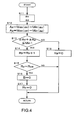
- FIG. 4 is a flowchart showing a control procedure for determining whether or not the lateral vibration in the bogie has been eliminated.
- a vibration suppression device is installed in a railway vehicle 1 shown in FIG. 1 .
- the railway vehicle 1 comprises a bogie 3 that travels along a pair of rails 2 extending in parallel, and a vehicle body 10 that is supported by the bogie 3 and carries people and objects.
- the bogie 3 is provided at each of a front portion and a rear portion of the vehicle body 10.
- the bogie 3 comprises left and right wheels 4 that roll along the pair of rails 2, an axle 5 that supports the wheels 4 rotatably, a bogie frame 6 that is supported by the axle 5 and carries the vehicle body 10, and left and right suspension springs 7 that are interposed between the axle 5 and the bogie frame 6 and absorb vertical direction movement of the axle 5.
- the wheel 4 has a tread 4a that contacts the rail 2 rotatably.
- the tread 4a is provided with a gradient that inclines relative to a rotary central axis of the wheel 4 to ensure smooth traveling in bend sections and suppress deviation to one side of the rail 2.
- the gradient of the left and right wheels 4 is formed such that the left and right wheels 4 are respectively oriented toward the inside of the left and right rails 2 by gravity of the railway vehicle 1.
- Left and right air springs 8 are interposed between the bogie frame 6 and the vehicle body 10.
- the air springs 8 support the vehicle body 10 relative to the bogie 3, and absorb vertical direction movement of the bogie 3.
- a damper 9 is disposed between the bogie 3 and the vehicle body 10.
- the damper 9 extends and compresses in a horizontal lateral direction (to be referred to hereafter as a "lateral direction") relative to an advancement direction of the railway vehicle 1 in order to suppress vibration in the lateral direction of the vehicle body 10.
- the damper 9 is a variable damping force damper in which a resistance applied to hydraulic oil (hydraulic fluid) that flows as the damper 9 extends and compresses is variable, and forms a semi-active suspension.
- the damping force of the damper 9 is switched continuously by signals output from a controller 20 installed in the vehicle.
- the controller 20 is constituted by a CPU, ROM, RAM, and so on, and controls an operation of the damper 9 on the basis of signals from various sensors.
- the vehicle body 10 is provided with an acceleration sensor 15 serving as means for detecting acceleration of the vehicle body 10.
- An acceleration signal detected by the acceleration sensor 15 is output to the controller 20.
- the acceleration sensor 15 detects biaxial acceleration, i.e. acceleration ax in the lateral direction of the vehicle body 10 and acceleration az in the vertical direction of the vehicle body 10. It should be noted that the acceleration ax and the acceleration az may be detected by provided two acceleration sensors that each detect acceleration on a single axis as the means for detecting acceleration of the vehicle body 10.
- the damper 9 comprises a cylinder 32 in which hydraulic oil is sealed, a piston 34 accommodated slidably within the cylinder 32, and a rod 33, one end of which is coupled to the piston 34 and another end of which extends to the external cylinder 32.
- the cylinder 32 is connected to one of the bogie 3 and the vehicle body 10, and the rod 33 is connected to the other.
- the piston 34 slides within the cylinder 32.
- the internal cylinder 32 is partitioned by the piston 34 into a rod side pressure chamber 35 and an end side pressure chamber 36. Further, a tank chamber 37 which is independent of the rod side pressure chamber 35 and the end side pressure chamber 36 is provided in the internal of the cylinder 32.
- the damper 9 comprises a uniflow passage 41 that leads the hydraulic oil from the rod side pressure chamber 35 into the tank chamber 37, an extension side check valve 51 that is provided in a passage connecting the end side pressure chamber 36 to the tank chamber 37 and only allows the hydraulic oil to flow from the tank chamber 37 into the end side pressure chamber 36, a compression side check valve 52 that is provided on the piston 34 and only allows the hydraulic oil to flow from the end side pressure chamber 36 to the rod side pressure chamber 35, and an orifice 53 that applies resistance to hydraulic oil flowing through a passage that connects the rod side pressure chamber 35 to the tank chamber 37.
- a solenoid proportional relief valve 42 and a damping valve 43 are equipped in series in the uniflow passage 41 together with an electromagnetic switch valve 44 that selectively leads the hydraulic oil to the solenoid proportional relief valve 42 or the damping valve 43.
- a valve-opening pressure of the solenoid proportional relief valve 42 is set in accordance with a signal output from the controller 20.
- the damping valve 43 generates a damping force that is proportionate to the piston speed of the damper 9.
- the position of the electromagnetic switch valve 44 is switched by a signal output from the controller 20.
- the damper 9 comprises a communication passage 45 that connects the rod side pressure chamber 35 to the end side pressure chamber 36.
- An extension side unloading valve 46 having a valve-opening position 46a in which the damper 9 is unloaded during an extension side stroke of an extension/compression operation of the damper 9 is interposed in the communication passage 45.
- the damper 9 also comprises a communication passage 47 that connects the end side pressure chamber 36 to the tank chamber 37.
- a compression side unloading valve 48 having a valve-opening position 48a in which the damper 9 is unloaded during a compression side stroke of the extension/compression operation of the damper 9 is interposed in the communication passage 47.
- the extension side unloading valve 46 and compression side unloading valve 48 operate during skyhook semi-active control, and are opened and closed in accordance with a signal output by the controller 20.
- the controller 20 closes both the extension side unloading valve 46 and the compression side unloading valve 48 such that these two valves are OFF. Further, the controller 20 controls the solenoid proportional relief valve 42 to a constant valve-opening pressure by switching the electromagnetic switch valve 44 to a position in which the hydraulic oil is led to the solenoid proportional relief valve 42. Hence, when skyhook semi-active control is not performed, the damper 9 functions as a passive damper.
- the extension side check valve 51 closes and the compression side check valve 52 opens such that an amount of hydraulic oil corresponding to an infiltration volume of the rod 33 flows from the rod side pressure chamber 35 into the tank chamber 37 through the orifice 53 and the uniflow passage 41.
- the compression side check valve 52 closes and the extension side check valve 51 opens such that the hydraulic oil in the rod side pressure chamber 35 flows from the tank chamber 37 into the end side pressure chamber 36 through the orifice 53 and the uniflow passage 41.
- the area ratio of the piston 34 and the rod 33 is set at 2:1, and therefore the flow rate of the hydraulic oil that flows out of the rod side pressure chamber 35 is equal in the compression side stroke and the extension side stroke of the damper 9.
- the flow rate of the hydraulic oil flowing through the orifice 53 and the uniflow passage 41 is equal in the compression side stroke and the extension side stroke, and therefore an identical damping characteristic is obtained.
- the damper 9 when the damper 9 does not perform skyhook semi-active control, the damper 9 enters an on-load state, in which damping force is generated, during both the extension side stroke and the compression side stroke.
- the electromagnetic switch valve 44 is switched to a position in which the hydraulic oil is led to the damping valve 43, whereby the damper 9 functions as a passive damper having a constant damping coefficient.
- the controller 20 opens one of the extension side unloading valve 46 and the compression side unloading valve 48 to switch that valve ON, and closes the other valve to switch that valve OFF. Further, the controller 20 controls the valve-opening pressure of the solenoid proportional relief valve 42 by switching the electromagnetic switch valve 44 to a position in which the hydraulic oil is led to the solenoid proportional relief valve 42.
- skyhook semi-active control (first control means) will be described in detail.
- a damping force F is calculated by the controller 20 in the following manner, where X is a lateral direction displacement of the vehicle body 10, Y is a lateral direction displacement of the bogie 3, dX/dt is a lateral direction absolute velocity of the vehicle body 10, d (X-Y)/dt is a lateral direction relative velocity between the vehicle body 10 and the bogie 3, and Cs is a sky-hook damping coefficient.
- the lateral direction absolute velocity dX/dt of the vehicle body 10 is calculated by subjecting the lateral direction acceleration ax of the vehicle body 10, which is detected by the acceleration sensor 15, to integration processing in the controller 20. Further, the lateral direction relative velocity d (X-Y)/dt between the vehicle body 10 and the bogie 3 is detected by a stroke sensor or the like that detects the stroke of the damper 9.
- the damping force F calculated by the controller 20 is output to the damper 9 as a control command.
- the damper 9 then controls the operations of various valves, such as the extension side unloading valve 46, the compression side unloading valve 48, and the solenoid proportional relief valve 42, in the manner described above to generate the damping force F corresponding to the control command.
- the damping force F of the damper 9 is controlled to a value as close to zero to ensure that the lateral vibration of the bogie 3 is not transmitted to the vehicle body 10.
- the controller 20 determines whether or not lateral vibration has occurred in the bogie 3, and having determined the presence of lateral vibration in the bogie 3, the controller 20 switches the control mode of the damper 9 from skyhook semi-active control to a control mode (second control means) in which the damper 9 acts to suppress the lateral vibration of the bogie 3.
- the controller 20 causes the damper 9 to perform sky-hook semi-active control by calculating the damping force F on the basis of Equations (1) and (2) described above to suppress lateral vibration of the vehicle body 10.
- the controller 20 controls the damping force of the damper 9 in accordance with the lateral direction absolute velocity dX/dt of the vehicle body 10.
- the controller 20 makes an opening command issued to the solenoid proportional relief valve 42 constant and switches both the extension side unloading valve 46 and the compression side unloading valve 48 OFF.
- the damper 9 functions as a passive damper that generates damping force in accordance with the relative velocity between the bogie 3 and the vehicle body 10, regardless of the lateral direction absolute velocity dX/dt of the vehicle body 10.
- the damper 9 acts to suppress the lateral vibration of the bogie 3. It should be noted that by constituting the solenoid proportional relief valve 42 to operate mechanically such that the damping force generated by the damper 9 becomes constant, lateral vibration in the bogie 3 can be suppressed more effectively.
- the damping force of the damper 9 is generated in accordance with the lateral direction speed of the vehicle body 10 through sky-hook semi-active control, and when lateral vibration occurs in the bogie 3, the damping force of the damper 9 is generated according to the relative velocity between the bogie 3 and the vehicle body 10.
- the bogie 3 meanders, causing the vehicle body 10 to oscillate in the lateral direction, the vehicle body frame 6 to oscillate in the vertical direction via the suspension springs 7 due to the gradient provided on the tread 4a of the wheels 4. As a result, the vehicle body 10 oscillates in the vertical direction via the air springs 8. If skyhook semi-active control is performed by the damper 9 at this time, a lateral direction acceleration amplitude (acceleration variation) Ax of the vehicle body 10 is suppressed to be small, but a vertical direction acceleration amplitude (acceleration variation) Az of the vehicle body 10 cannot be suppressed.
- the controller 20 determines whether or not lateral vibration has occurred in the bogie 3 on the basis of the lateral direction acceleration ax of the vehicle body 10 and the vertical direction acceleration az of the vehicle body 10, which are detected by the acceleration sensor 15.
- the detection signal detected by the acceleration sensor 15 is subjected to filter processing to read the lateral direction acceleration ax and vertical direction acceleration az of the vehicle body 10.
- the acceleration amplitude Ax which is the difference between a maximum value Max (ax) and a minimum value Min (ax) of the acceleration ax read within a predetermined time period
- the acceleration amplitude Az which is the difference between a maximum value Max (az) and a minimum value Min (az) of the acceleration az read within a predetermined time period
- the routine advances to a step 8, where an abnormality count value Cz is cleared.
- the routine advances to a step 4, where the abnormality count value Cz is incremented by one.
- step 5 When it is determined in the step 5 that the count value Cz has reached the determination value Cza, it is determined that lateral vibration has occurred in the bogie 3, and therefore the routine advances to a step 6, where a lateral vibration occurrence determination bit B is established.
- the control mode of the damper 9 is switched (switching control means) in a separate routine from sky-hook semi-active control to the control mode in which the damper 9 acts to suppress the lateral vibration of the bogie 3.
- the lateral vibration of the bogie 3 is suppressed by the operation of the damper 9, and thus the traveling stability of the railway vehicle 1 is increased.
- the occurrence of lateral vibration in the bogie 3 is determined on the basis of both the lateral direction acceleration ax of the vehicle body 10 and the vertical direction acceleration az of the vehicle body 10, but as noted above, when skyhook semi-active control is performed by the damper 9, the lateral direction acceleration amplitude Ax of the vehicle body 10 is suppressed to be small. Therefore, the occurrence of lateral vibration in the bogie 3 may be determined using only the vertical direction acceleration amplitude Az, which is not easily affected by sky-hook semi-active control. More specifically, the number of times that the acceleration amplitude Az reaches or exceeds a reference value may be counted such that when the count value reaches a determination value, it is determined that lateral vibration has occurred in the bogie 3.
- the number of times that either value of the vertical direction acceleration amplitude Az and lateral direction acceleration amplitude Ax of the vehicle body 10 reaches or exceeds a reference value may be counted such that when the count value reaches a determination value, it is determined that lateral vibration has occurred in the bogie 3.
- the number of times that the values of both the vertical direction acceleration amplitude Az and lateral direction acceleration amplitude Ax reach or exceed a reference value may be counted such that when the count value reaches a determination value, it is determined that lateral vibration has occurred in the bogie 3.
- a sum ax+az of the lateral direction acceleration ax and the vertical direction acceleration az may be used, and the number of times that this sum ax+az reaches or exceeds a reference value may be counted such that when the count value reaches a determination value, it is determined that lateral vibration has occurred in the bogie 3.
- the detection signal detected by the acceleration sensor 15 is subjected to filter processing to read the lateral direction acceleration ax and vertical direction acceleration az of the vehicle body 10.
- the acceleration amplitude Ax which is the difference between the maximum value Max (ax) and minimum value Min (ax) of the acceleration ax read within a predetermined time period
- the acceleration amplitude Az which is the difference between the maximum value Max (az) and minimum value Min (az) of the acceleration az read within a predetermined time period
- the routine advances to a step 18, where an abnormality count value Rz is cleared.
- the routine advances to a step 14, where the abnormality count value Rz is incremented by one.
- step 15 When it is determined in the step 15 that the count value Rz has reached the determination value Rza, it is determined that lateral vibration in the bogie 3 has been eliminated, and therefore the routine advances to a step 16, where the lateral vibration occurrence determination bit B is cleared.
- lateral vibration of the vehicle body 10 is suppressed by subjecting the damping force of the damper 9 to skyhook semi-active control, thereby maintaining the passenger comfort in a favorable state.
- the operation of the damper 9 is switched, and as a result, the high-frequency lateral vibration of the bogie 3 is suppressed, enabling an improvement in the traveling stability of the railway vehicle 1. Hence, deterioration of the passenger comfort of the railway vehicle 1 can be prevented even when lateral vibration occurs in the bogie 3.
- the damper 9 functions as a passive damper having a constant damping force, and therefore the lateral vibration of the bogie 3 is suppressed by the damping force generated by the damper 9, leading to an improvement in the traveling stability of the railway vehicle 1.
- both the extension side unloading valve 46 and the compression side unloading valve 48 are closed to OFF such that the damper 9 does not enter an unloaded state during an extension/compression operation. Therefore, the damper 9 generates damping force in both the compression side stroke and the extension side stroke, whereby lateral vibration of the bogie 3 is suppressed, enabling an improvement in the traveling stability of the railway vehicle 1.
- the occurrence of lateral vibration in the bogie 3 is determined on the basis of an acceleration detection signal, which is detected by the acceleration sensor 15 provided in the vehicle body 10. Hence, there is no need to provide the bogie 3 with an acceleration sensor or the like, and as a result, increases in the cost of the device can be suppressed.
- the occurrence of lateral vibration in the bogie 3 is determined on the basis of both the lateral direction acceleration and the vertical direction acceleration of the vehicle body 10, which are detected by the biaxial acceleration sensor 15, the occurrence of lateral vibration in the bogie 3 can be determined even more accurately.
- the electromagnetic switch valve 44 shown in FIG. 2 may be switched to a position for leading the hydraulic oil into the damping valve 43 such that the damper 9 functions as a passive damper having a constant damping coefficient.
- the position of the electromagnetic switch valve 44 is switched such that the hydraulic oil flowing through the uniflow passage 41 is led to the damping valve 43.
- the damping valve 43 increases the damping force in proportion to the piston speed of the damper 9, and therefore lateral vibration of the bogie 3 is suppressed by the damping force of the damper 9, enabling an improvement in the traveling stability of the railway vehicle 1.
Landscapes
- Engineering & Computer Science (AREA)
- Mechanical Engineering (AREA)
- Vehicle Body Suspensions (AREA)
- Vibration Prevention Devices (AREA)
Abstract
Description
- This invention relates to a vibration suppression device that suppresses vibration in a railway vehicle.
- A semi-active suspension that does not require power is installed in a railway vehicle to suppress aerodynamic vibration in a vehicle body.
- As disclosed in
JP10-297485A - The controller controls the operation of the damper using the sky-hook semi-active control rule, whereby the vibration energy of the damper is used to suppress lateral vibration in the vehicle body.
- To ensure smooth traveling in a bend section and suppress deviation to one side of the rails, a tread on the wheels of the railway vehicle, which contact the rails rotatably, is provided with a gradient so that the left and right wheels are respectively oriented toward the inside of the rails. Hence, when the railway vehicle travels along a line section, the bogie tends to be snake motion.
- This snake motion of the bogie is suppressed by setting the gradient provided on the tread of the wheel appropriately, setting the hardness of a bush provided on the suspension appropriately, and so on.
- However, when wear on the tread of the wheel and deterioration of the bush advance with age, or when the railway vehicle travels in a location having poor track conditions, large, high-frequency lateral vibration may occur in the bogie.
- In skyhook semi-active control, a damping force of the damper in a direction that causes the vehicle body to vibrate is set at zero. Hence, when large, high-frequency lateral vibration occurs in the bogie of a railway vehicle installed with a semi-active suspension and sky-hook semi-active control is performed, lateral vibration of the vehicle body is suppressed, but since the damping force of the damper is insufficient, it may be impossible to suppress lateral vibration of the bogie sufficiently. In this case, the vibration of the bogie is superimposed on the vibration of the vehicle body, and as a result, the passenger comfort of the vehicle deteriorates.
- This invention has been designed in consideration of the problems described above, and it is an object thereof to provide a vibration suppression device for a railway vehicle installed with a semi-active suspension, which is capable of preventing deterioration of the passenger comfort of the railway vehicle even when lateral vibration occurs in a bogie.
- In order to achieve above object, this invention provides a vibration suppression device for a railway vehicle, which suppresses vibration in the railway vehicle. The vibration suppression device for a railway vehicle comprises a damper having a variable damping force, which extends and compresses in accordance with lateral vibration of a vehicle body relative to a bogie, first control means that control the damping force of the damper using sky-hook semi-active control in order to suppress the lateral vibration of the vehicle body, vertical direction acceleration detecting means that detect acceleration in a vertical direction of the vehicle body, determining means that determine whether or not lateral vibration has occurred in the bogie on the basis of the acceleration detected by the vertical direction acceleration detecting means, second control means that cause the damper to operate so as to suppress the lateral vibration of the bogie and switching control means that switch from the first control means to the second control means when lateral vibration is determined to have occurred in the bogie.
-
FIG. 1 is a system diagram of a vibration suppression device for a railway vehicle according to an embodiment of this invention. -
FIG. 2 is a constitutional diagram of a variable damping force damper. -
FIG. 3 is a flowchart showing a control procedure for determining whether or not lateral vibration has occurred in a bogie. -
FIG. 4 is a flowchart showing a control procedure for determining whether or not the lateral vibration in the bogie has been eliminated. - Embodiments of this invention will be described below with reference to the drawings.
- A vibration suppression device according to an embodiment of this invention is installed in a
railway vehicle 1 shown inFIG. 1 . - The
railway vehicle 1 comprises abogie 3 that travels along a pair ofrails 2 extending in parallel, and avehicle body 10 that is supported by thebogie 3 and carries people and objects. - One
bogie 3 is provided at each of a front portion and a rear portion of thevehicle body 10. Thebogie 3 comprises left andright wheels 4 that roll along the pair ofrails 2, anaxle 5 that supports thewheels 4 rotatably, abogie frame 6 that is supported by theaxle 5 and carries thevehicle body 10, and left andright suspension springs 7 that are interposed between theaxle 5 and thebogie frame 6 and absorb vertical direction movement of theaxle 5. - The
wheel 4 has atread 4a that contacts therail 2 rotatably. Thetread 4a is provided with a gradient that inclines relative to a rotary central axis of thewheel 4 to ensure smooth traveling in bend sections and suppress deviation to one side of therail 2. The gradient of the left andright wheels 4 is formed such that the left andright wheels 4 are respectively oriented toward the inside of the left andright rails 2 by gravity of therailway vehicle 1. - Left and
right air springs 8 are interposed between thebogie frame 6 and thevehicle body 10. Theair springs 8 support thevehicle body 10 relative to thebogie 3, and absorb vertical direction movement of thebogie 3. - A
damper 9 is disposed between thebogie 3 and thevehicle body 10. Thedamper 9 extends and compresses in a horizontal lateral direction (to be referred to hereafter as a "lateral direction") relative to an advancement direction of therailway vehicle 1 in order to suppress vibration in the lateral direction of thevehicle body 10. - The
damper 9 is a variable damping force damper in which a resistance applied to hydraulic oil (hydraulic fluid) that flows as thedamper 9 extends and compresses is variable, and forms a semi-active suspension. The damping force of thedamper 9 is switched continuously by signals output from acontroller 20 installed in the vehicle. - The
controller 20 is constituted by a CPU, ROM, RAM, and so on, and controls an operation of thedamper 9 on the basis of signals from various sensors. - The
vehicle body 10 is provided with anacceleration sensor 15 serving as means for detecting acceleration of thevehicle body 10. An acceleration signal detected by theacceleration sensor 15 is output to thecontroller 20. - The
acceleration sensor 15 detects biaxial acceleration, i.e. acceleration ax in the lateral direction of thevehicle body 10 and acceleration az in the vertical direction of thevehicle body 10. It should be noted that the acceleration ax and the acceleration az may be detected by provided two acceleration sensors that each detect acceleration on a single axis as the means for detecting acceleration of thevehicle body 10. - Next, referring to
FIG. 2 , thedamper 9 will be described. - The
damper 9 comprises acylinder 32 in which hydraulic oil is sealed, apiston 34 accommodated slidably within thecylinder 32, and arod 33, one end of which is coupled to thepiston 34 and another end of which extends to theexternal cylinder 32. Thecylinder 32 is connected to one of thebogie 3 and thevehicle body 10, and therod 33 is connected to the other. When thevehicle body 10 displaces relative to thebogie 3 in the lateral direction, thepiston 34 slides within thecylinder 32. - The
internal cylinder 32 is partitioned by thepiston 34 into a rodside pressure chamber 35 and an endside pressure chamber 36. Further, atank chamber 37 which is independent of the rodside pressure chamber 35 and the endside pressure chamber 36 is provided in the internal of thecylinder 32. - The
damper 9 comprises auniflow passage 41 that leads the hydraulic oil from the rodside pressure chamber 35 into thetank chamber 37, an extensionside check valve 51 that is provided in a passage connecting the endside pressure chamber 36 to thetank chamber 37 and only allows the hydraulic oil to flow from thetank chamber 37 into the endside pressure chamber 36, a compressionside check valve 52 that is provided on thepiston 34 and only allows the hydraulic oil to flow from the endside pressure chamber 36 to the rodside pressure chamber 35, and anorifice 53 that applies resistance to hydraulic oil flowing through a passage that connects the rodside pressure chamber 35 to thetank chamber 37. - A solenoid
proportional relief valve 42 and adamping valve 43 are equipped in series in theuniflow passage 41 together with anelectromagnetic switch valve 44 that selectively leads the hydraulic oil to the solenoidproportional relief valve 42 or thedamping valve 43. A valve-opening pressure of the solenoidproportional relief valve 42 is set in accordance with a signal output from thecontroller 20. Thedamping valve 43 generates a damping force that is proportionate to the piston speed of thedamper 9. The position of theelectromagnetic switch valve 44 is switched by a signal output from thecontroller 20. - The
damper 9 comprises acommunication passage 45 that connects the rodside pressure chamber 35 to the endside pressure chamber 36. An extensionside unloading valve 46 having a valve-opening position 46a in which thedamper 9 is unloaded during an extension side stroke of an extension/compression operation of thedamper 9 is interposed in thecommunication passage 45. - The
damper 9 also comprises acommunication passage 47 that connects the endside pressure chamber 36 to thetank chamber 37. A compressionside unloading valve 48 having a valve-opening position 48a in which thedamper 9 is unloaded during a compression side stroke of the extension/compression operation of thedamper 9 is interposed in thecommunication passage 47. - The extension
side unloading valve 46 and compressionside unloading valve 48 operate during skyhook semi-active control, and are opened and closed in accordance with a signal output by thecontroller 20. - Next, an operation of the
damper 9 will be described. - First, a case in which the
damper 9 does not perform skyhook semi-active control will be described. - The
controller 20 closes both the extensionside unloading valve 46 and the compressionside unloading valve 48 such that these two valves are OFF. Further, thecontroller 20 controls the solenoidproportional relief valve 42 to a constant valve-opening pressure by switching theelectromagnetic switch valve 44 to a position in which the hydraulic oil is led to the solenoidproportional relief valve 42. Hence, when skyhook semi-active control is not performed, thedamper 9 functions as a passive damper. - In the compression side stroke of the
damper 9, the extensionside check valve 51 closes and the compressionside check valve 52 opens such that an amount of hydraulic oil corresponding to an infiltration volume of therod 33 flows from the rodside pressure chamber 35 into thetank chamber 37 through theorifice 53 and theuniflow passage 41. - In the extension side stroke of the
damper 9, the compressionside check valve 52 closes and the extensionside check valve 51 opens such that the hydraulic oil in the rodside pressure chamber 35 flows from thetank chamber 37 into the endside pressure chamber 36 through theorifice 53 and theuniflow passage 41. - The area ratio of the
piston 34 and therod 33 is set at 2:1, and therefore the flow rate of the hydraulic oil that flows out of the rodside pressure chamber 35 is equal in the compression side stroke and the extension side stroke of thedamper 9. In other words, the flow rate of the hydraulic oil flowing through theorifice 53 and theuniflow passage 41 is equal in the compression side stroke and the extension side stroke, and therefore an identical damping characteristic is obtained. - Hence, when the
damper 9 does not perform skyhook semi-active control, thedamper 9 enters an on-load state, in which damping force is generated, during both the extension side stroke and the compression side stroke. - It should be noted that when an abnormality or the like occurs in the
controller 20, theelectromagnetic switch valve 44 is switched to a position in which the hydraulic oil is led to the dampingvalve 43, whereby thedamper 9 functions as a passive damper having a constant damping coefficient. - Next, a case in which the
damper 9 performs skyhook semi-active control will be described. - During sky-hook semi-active control, the
controller 20 opens one of the extensionside unloading valve 46 and the compressionside unloading valve 48 to switch that valve ON, and closes the other valve to switch that valve OFF. Further, thecontroller 20 controls the valve-opening pressure of the solenoidproportional relief valve 42 by switching theelectromagnetic switch valve 44 to a position in which the hydraulic oil is led to the solenoidproportional relief valve 42. - During sky-hook semi-active control in which the extension
side unloading valve 46 is opened to be ON and the compressionside unloading valve 48 is closed to be OFF, the hydraulic oil in the rodside pressure chamber 35 flows into the endside pressure chamber 36 through the extensionside unloading valve 46 in the extension side stroke of thedamper 9. Accordingly, the damping force generated by thedamper 9 becomes extremely low due to pressure loss in the passage. In the compression side stroke of thedamper 9, on the other hand, the hydraulic oil in the rodside pressure chamber 35 flows into thetank chamber 37 through theuniflow passage 41, and a damping force based on a control command is generated by the solenoidproportional relief valve 42. - During sky-hook semi-active control in which the extension
side unloading valve 46 is closed to be OFF and the compressionside unloading valve 48 is opened to be ON, the hydraulic oil in the rodside pressure chamber 35 flows into the endside pressure chamber 36 through theuniflow passage 41 in the extension side stroke of thedamper 9, and a damping force based on a control command is generated by the solenoidproportional relief valve 42. In the compression side stroke of thedamper 9, on the other hand, the hydraulic oil in the endside pressure chamber 36 flows into thetank chamber 37 through the compressionside unloading valve 48. Accordingly, the damping force generated by thedamper 9 becomes extremely low due to pressure loss in the passage. - Hence, by switching one of the extension
side unloading valve 46 and the compressionside unloading valve 48 ON during skyhook semi-active control, a damping force can be generated in only one of the extension side stroke and the compression side stroke. - Next, skyhook semi-active control (first control means) will be described in detail.
- In the sky-hook semi-active control law, it is imagined that an immobile side wall is present on the side of the
vehicle body 10 and an imaginary damper is disposed between the side wall and thevehicle body 10. When the direction of the damping force generated by the imaginary damper is identical to the direction of the damping force generated by thedamper 9, the damping force generated by the imaginary damper is generated as the damping force of thedamper 9. Further, when the direction of the damping force generated by the imaginary damper is opposite to the direction of the damping force generated by thedamper 9, the damping force of thedamper 9 is set to be extremely low. - As an example of sky-hook semi-active control, a damping force F is calculated by the
controller 20 in the following manner, where X is a lateral direction displacement of thevehicle body 10, Y is a lateral direction displacement of thebogie 3, dX/dt is a lateral direction absolute velocity of thevehicle body 10, d (X-Y)/dt is a lateral direction relative velocity between thevehicle body 10 and thebogie 3, and Cs is a sky-hook damping coefficient. The lateral direction absolute velocity dX/dt of thevehicle body 10 is calculated by subjecting the lateral direction acceleration ax of thevehicle body 10, which is detected by theacceleration sensor 15, to integration processing in thecontroller 20. Further, the lateral direction relative velocity d (X-Y)/dt between thevehicle body 10 and thebogie 3 is detected by a stroke sensor or the like that detects the stroke of thedamper 9. - When (dX/dt) x {d (X-Y)/dt} ≥ 0, the damping force F is calculated using the following Equation (1).
- F = CS x (dX/dt) (1)
- When (dX/dt) x {d (X-Y)/dt} < 0, the damping force F is calculated as close to zero using the following Equation (2).
- F ≈ 0 (2)
- The damping force F calculated by the
controller 20 is output to thedamper 9 as a control command. Thedamper 9 then controls the operations of various valves, such as the extensionside unloading valve 46, the compressionside unloading valve 48, and the solenoidproportional relief valve 42, in the manner described above to generate the damping force F corresponding to the control command. - In a normal passive damper, a damping force corresponding to the piston speed of the damper is generated irrespective of the extension/compression direction. Therefore, depending on the vibration direction of the
bogie 3 andvehicle body 10, vibration in thevehicle body 10 may actually increase. In sky-hook semi-active control, the damping force of thedamper 9 in the direction that causes thevehicle body 10 to vibrate is controlled to a value as close to zero by the extensionside unloading valve 46 and compressionside unloading valve 48, as shown above in Equation (2). More specifically, when the vibration direction of thebogie 3 andvehicle body 10 is identical but the speed of thebogie 3 exceeds the speed of thevehicle body 10, the damping force F of thedamper 9 is controlled to a value as close to zero to ensure that the lateral vibration of thebogie 3 is not transmitted to thevehicle body 10. - When wear on the
tread 4a of thewheel 4 and deterioration of the bush advance with age, or when traveling in a location having poor track conditions, lateral vibration, which is large, high-frequency rolling, may occur in thebogie 3. - When lateral vibration occurs in the
bogie 3 and sky-hook semi-active control is performed similarly to normal travel, the damping force of thedamper 9 in the direction that causes thevehicle body 10 to vibrate is set at zero, and therefore a force for suppressing the lateral vibration does not act on thebogie 3. As a result, lateral vibration of thebogie 3 may be encouraged, and in this case, the lateral vibration of thebogie 3 is superimposed on the lateral vibration of thevehicle body 10 such that high speed travel of therailway vehicle 1 is impaired. - To deal with this problem, the
controller 20 determines whether or not lateral vibration has occurred in thebogie 3, and having determined the presence of lateral vibration in thebogie 3, thecontroller 20 switches the control mode of thedamper 9 from skyhook semi-active control to a control mode (second control means) in which thedamper 9 acts to suppress the lateral vibration of thebogie 3. - More specifically, during normal travel in which lateral vibration does not occur in the
bogie 3, thecontroller 20 causes thedamper 9 to perform sky-hook semi-active control by calculating the damping force F on the basis of Equations (1) and (2) described above to suppress lateral vibration of thevehicle body 10. In other words, thecontroller 20 controls the damping force of thedamper 9 in accordance with the lateral direction absolute velocity dX/dt of thevehicle body 10. - On the other hand, when lateral vibration occurs in the
bogie 3, thecontroller 20 makes an opening command issued to the solenoidproportional relief valve 42 constant and switches both the extensionside unloading valve 46 and the compressionside unloading valve 48 OFF. As a result, sky-hook semi-active control is halted, and thedamper 9 functions as a passive damper that generates damping force in accordance with the relative velocity between thebogie 3 and thevehicle body 10, regardless of the lateral direction absolute velocity dX/dt of thevehicle body 10. Thus, thedamper 9 acts to suppress the lateral vibration of thebogie 3. It should be noted that by constituting the solenoidproportional relief valve 42 to operate mechanically such that the damping force generated by thedamper 9 becomes constant, lateral vibration in thebogie 3 can be suppressed more effectively. - Hence, during normal travel, the damping force of the
damper 9 is generated in accordance with the lateral direction speed of thevehicle body 10 through sky-hook semi-active control, and when lateral vibration occurs in thebogie 3, the damping force of thedamper 9 is generated according to the relative velocity between thebogie 3 and thevehicle body 10. - Next, a method of determining whether or not lateral vibration has occurred in the
bogie 3 will be described. - When lateral vibration occurs in the
bogie 3, thebogie 3 meanders, causing thevehicle body 10 to oscillate in the lateral direction, thevehicle body frame 6 to oscillate in the vertical direction via the suspension springs 7 due to the gradient provided on thetread 4a of thewheels 4. As a result, thevehicle body 10 oscillates in the vertical direction via the air springs 8. If skyhook semi-active control is performed by thedamper 9 at this time, a lateral direction acceleration amplitude (acceleration variation) Ax of thevehicle body 10 is suppressed to be small, but a vertical direction acceleration amplitude (acceleration variation) Az of thevehicle body 10 cannot be suppressed. - Therefore, by detecting the vertical direction acceleration amplitude Az of the
vehicle body 10 together with the lateral direction acceleration amplitude Ax of thevehicle body 10, it is possible to determine accurately that lateral vibration has occurred in thebogie 3. Thecontroller 20 determines whether or not lateral vibration has occurred in thebogie 3 on the basis of the lateral direction acceleration ax of thevehicle body 10 and the vertical direction acceleration az of thevehicle body 10, which are detected by theacceleration sensor 15. - Next, a control procedure for determining whether or not lateral vibration has occurred in the
bogie 3 will be described with reference to a flowchart shown inFIG. 3 . The following procedure is executed by thecontroller 20. - First, in a
step 1, the detection signal detected by theacceleration sensor 15 is subjected to filter processing to read the lateral direction acceleration ax and vertical direction acceleration az of thevehicle body 10. - Next, in a
step 2, the acceleration amplitude Ax, which is the difference between a maximum value Max (ax) and a minimum value Min (ax) of the acceleration ax read within a predetermined time period, is calculated. Further, the acceleration amplitude Az, which is the difference between a maximum value Max (az) and a minimum value Min (az) of the acceleration az read within a predetermined time period, is calculated in a similar manner. - Next, in a
step 3, a determination is made as to whether or not a sum αAx+βAz of αAx, which is obtained by multiplying a lateral direction acceleration weighting coefficient α by the lateral direction acceleration amplitude Ax, and βAz, which is obtained by multiplying a vertical direction acceleration weighting coefficient β by the vertical direction acceleration amplitude Az, is equal to or greater than a predetermined reference value Max1. - When it is determined in the
step 3 that αAx+βAz is smaller than the reference value Max1, the routine advances to astep 8, where an abnormality count value Cz is cleared. - When it is determined in the
step 3 that αAx+βAz is equal to or greater than the reference value Max1, the routine advances to astep 4, where the abnormality count value Cz is incremented by one. - Next, in a
step 5, a determination is made as to whether or not the count value Cz has reached a predetermined determination value Cza. - When it is determined in the
step 5 that the count value Cz has reached the determination value Cza, it is determined that lateral vibration has occurred in thebogie 3, and therefore the routine advances to astep 6, where a lateral vibration occurrence determination bit B is established. - Finally, in a
step 7, the abnormality count value Cz is initialized, whereupon the routine is terminated. Thereafter, the procedure described above is repeated. - When the lateral vibration occurrence determination bit B is established in the manner described above, the control mode of the
damper 9 is switched (switching control means) in a separate routine from sky-hook semi-active control to the control mode in which thedamper 9 acts to suppress the lateral vibration of thebogie 3. As a result, the lateral vibration of thebogie 3 is suppressed by the operation of thedamper 9, and thus the traveling stability of therailway vehicle 1 is increased. - In the above description, the occurrence of lateral vibration in the
bogie 3 is determined on the basis of both the lateral direction acceleration ax of thevehicle body 10 and the vertical direction acceleration az of thevehicle body 10, but as noted above, when skyhook semi-active control is performed by thedamper 9, the lateral direction acceleration amplitude Ax of thevehicle body 10 is suppressed to be small. Therefore, the occurrence of lateral vibration in thebogie 3 may be determined using only the vertical direction acceleration amplitude Az, which is not easily affected by sky-hook semi-active control. More specifically, the number of times that the acceleration amplitude Az reaches or exceeds a reference value may be counted such that when the count value reaches a determination value, it is determined that lateral vibration has occurred in thebogie 3. - As another parameter for determining the occurrence of lateral vibration in the
bogie 3, the number of times that either value of the vertical direction acceleration amplitude Az and lateral direction acceleration amplitude Ax of thevehicle body 10 reaches or exceeds a reference value may be counted such that when the count value reaches a determination value, it is determined that lateral vibration has occurred in thebogie 3. - As another parameter for determining the occurrence of lateral vibration in the
bogie 3, the number of times that the values of both the vertical direction acceleration amplitude Az and lateral direction acceleration amplitude Ax reach or exceed a reference value may be counted such that when the count value reaches a determination value, it is determined that lateral vibration has occurred in thebogie 3. - As a further parameter for determining the occurrence of lateral vibration in the
bogie 3, a sum ax+az of the lateral direction acceleration ax and the vertical direction acceleration az may be used, and the number of times that this sum ax+az reaches or exceeds a reference value may be counted such that when the count value reaches a determination value, it is determined that lateral vibration has occurred in thebogie 3. - Next, a control procedure for determining whether or not lateral vibration in the
bogie 3 has been eliminated will be described with reference to a flowchart shown inFIG. 4 . The following procedure is executed by thecontroller 20. - First, in a step 11, the detection signal detected by the
acceleration sensor 15 is subjected to filter processing to read the lateral direction acceleration ax and vertical direction acceleration az of thevehicle body 10. - Next, in a step 12, the acceleration amplitude Ax, which is the difference between the maximum value Max (ax) and minimum value Min (ax) of the acceleration ax read within a predetermined time period, is calculated. Further, the acceleration amplitude Az, which is the difference between the maximum value Max (az) and minimum value Min (az) of the acceleration az read within a predetermined time period, is calculated in a similar manner.
- Next, in a step 13, a determination is made as to whether or not the sum αAx+βAz of αAx, which is obtained by multiplying the lateral direction acceleration weighting coefficient α by the lateral direction acceleration amplitude Ax, and βAz, which is obtained by multiplying the vertical direction acceleration weighting coefficient P by the vertical direction acceleration amplitude Az, is equal to or smaller than a predetermined reference value Min1.
- When it is determined in the step 13 that αAx+βAz is larger than the reference value Min1, the routine advances to a
step 18, where an abnormality count value Rz is cleared. - When it is determined in the step 13 that αAx+βAz is equal to or smaller than the reference value Min1, the routine advances to a step 14, where the abnormality count value Rz is incremented by one.
- Next, in a
step 15, a determination is made as to whether or not the count value Rz has reached a predetermined determination value Rza. - When it is determined in the
step 15 that the count value Rz has reached the determination value Rza, it is determined that lateral vibration in thebogie 3 has been eliminated, and therefore the routine advances to a step 16, where the lateral vibration occurrence determination bit B is cleared. - Finally, in a step 17, the abnormality count value Rz is initialized, whereupon the routine is terminated. Thereafter, the procedure described above is repeated.
- When the lateral vibration occurrence determination bit B is cleared in the manner described above, the control of the
damper 9 is returned to skyhook semi-active control in a separate routine. In so doing, lateral vibration of thevehicle body 10 is suppressed by an operation of thedamper 9, and thus passenger comfort is maintained in a favorable state. - According to the embodiment described above, the following actions and effects are exhibited.
- During normal travel, lateral vibration of the
vehicle body 10 is suppressed by subjecting the damping force of thedamper 9 to skyhook semi-active control, thereby maintaining the passenger comfort in a favorable state. On the other hand, when high-frequency lateral vibration occurs in thebogie 3, the operation of thedamper 9 is switched, and as a result, the high-frequency lateral vibration of thebogie 3 is suppressed, enabling an improvement in the traveling stability of therailway vehicle 1. Hence, deterioration of the passenger comfort of therailway vehicle 1 can be prevented even when lateral vibration occurs in thebogie 3. - Further, when lateral vibration occurs in the
bogie 3, thedamper 9 functions as a passive damper having a constant damping force, and therefore the lateral vibration of thebogie 3 is suppressed by the damping force generated by thedamper 9, leading to an improvement in the traveling stability of therailway vehicle 1. - Further, when lateral vibration occurs in the
bogie 3, both the extensionside unloading valve 46 and the compressionside unloading valve 48 are closed to OFF such that thedamper 9 does not enter an unloaded state during an extension/compression operation. Therefore, thedamper 9 generates damping force in both the compression side stroke and the extension side stroke, whereby lateral vibration of thebogie 3 is suppressed, enabling an improvement in the traveling stability of therailway vehicle 1. - Further, the occurrence of lateral vibration in the
bogie 3 is determined on the basis of an acceleration detection signal, which is detected by theacceleration sensor 15 provided in thevehicle body 10. Hence, there is no need to provide thebogie 3 with an acceleration sensor or the like, and as a result, increases in the cost of the device can be suppressed. - Further, when skyhook semi-active control is performed by the
damper 9, the lateral direction acceleration amplitude of thevehicle body 10 is suppressed to be small, but the vertical direction acceleration amplitude of thevehicle body 10 cannot be suppressed. Therefore, by determining whether or not lateral vibration has occurred in thebogie 3 on the basis of the vertical direction acceleration of thevehicle body 10, it is possible to determine accurately whether or not lateral vibration has occurred in thebogie 3. - Moreover, when the occurrence of lateral vibration in the
bogie 3 is determined on the basis of both the lateral direction acceleration and the vertical direction acceleration of thevehicle body 10, which are detected by thebiaxial acceleration sensor 15, the occurrence of lateral vibration in thebogie 3 can be determined even more accurately. - Other embodiments are illustrated below.
- (1) When lateral vibration occurs in the
bogie 3, sky-hook semi-active control may be continued such that the damping force F of thedamper 9 is calculated on the basis of Equation (1) and the skyhook damping coefficient Cs is set to be large. In this case, the damping force F of thedamper 9 increases when lateral vibration occurs in thebogie 3, and therefore lateral vibration of thebogie 3 is suppressed, enabling an improvement in the travelling stability of therailway vehicle 1. - (2) When lateral vibration occurs in the
bogie 3, theelectromagnetic switch valve 44 shown inFIG. 2 may be switched to a position for leading the hydraulic oil into the dampingvalve 43 such that thedamper 9 functions as a passive damper having a constant damping coefficient. - In this case, during normal travel the hydraulic oil flowing through the
uniflow passage 41 is led to the solenoidproportional relief valve 42 and the valve-opening pressure of the solenoidproportional relief valve 42 is subjected to skyhook semi-active control by thecontroller 20. As a result, lateral vibration of thevehicle body 10 is suppressed such that passenger comfort is maintained in a favorable state. - When lateral vibration occurs in the
bogie 3, the position of theelectromagnetic switch valve 44 is switched such that the hydraulic oil flowing through theuniflow passage 41 is led to the dampingvalve 43. The dampingvalve 43 increases the damping force in proportion to the piston speed of thedamper 9, and therefore lateral vibration of thebogie 3 is suppressed by the damping force of thedamper 9, enabling an improvement in the traveling stability of therailway vehicle 1. - This invention is not limited to the embodiments described above, and may of course be subjected to various modifications within the scope of the technical spirit thereof.
Claims (9)
- A vibration suppression device for a railway vehicle (1), which suppresses vibration in the railway vehicle (1), comprising:a damper (9) having a variable damping force, which extends and compresses in accordance with lateral vibration of a vehicle body (10) relative to a bogie (3);first control means that control the damping force of the damper (9) using sky-hook semi-active control in order to suppress the lateral vibration of the vehicle body (10);vertical direction acceleration detecting means (15) that detect acceleration in a vertical direction of the vehicle body (10);determining means that determine whether or not lateral vibration has occurred in the bogie (3) on the basis of the acceleration detected by the vertical direction acceleration detecting means (15);second control means that cause the damper (9) to operate so as to suppress the lateral vibration of the bogie (3); andswitching control means that switch from the first control means to the second control means when lateral vibration is determined to have occurred in the bogie (3).
- The vibration suppression device for a railway vehicle (1) as defined in Claim 1, wherein the second control means cause the damper (9) to function as a passive damper.
- The vibration suppression device for a railway vehicle (1) as defined in Claim 1, wherein the second control means generate a damping force in accordance with a relative velocity between the vehicle body (10) and the bogie (3).
- The vibration suppression device for a railway vehicle (1) as defined in Claim 1, wherein the second control means make the damping force of the damper (9) constant.
- The vibration suppression device for a railway vehicle (1) as defined in Claim 1, wherein the second control means make a damping coefficient of the damper (9) constant.
- The vibration suppression device for a railway vehicle (1) as defined in Claim 1, wherein the first control means perform control such that the damping force of the damper (9) is generated in only one of an extension side stroke and a compression side stroke, and
the second control means perform control such that the damping force of the damper (9) is generated in both the extension side stroke and the compression side stroke. - The vibration suppression device for a railway vehicle (1) as defined in Claim 6, wherein the first control means perform control such that the damping force of the damper (9) is not generated in a direction for causing the vehicle body to vibrate.
- The vibration suppression device for a railway vehicle (1) as defined in any one of Claim 1 through Claim 7, further comprising lateral direction acceleration detecting means (15) that detect acceleration in a lateral direction of the vehicle body,
wherein the first control means control the damping force of the damper (9) in accordance with an absolute velocity in the lateral direction of the vehicle body (10), which is calculated on the basis of the acceleration detected by the lateral direction acceleration detecting means (15). - The vibration suppression device for a railway vehicle (1) as defined in Claim 8, wherein the determining means determine whether or not lateral vibration has occurred in the bogie (3) on the basis of the acceleration detected by the vertical direction acceleration detecting means (15) and the acceleration detected by the lateral direction acceleration detecting means (15).
Applications Claiming Priority (1)
| Application Number | Priority Date | Filing Date | Title |
|---|---|---|---|
| KR1020070076123A KR101300893B1 (en) | 2007-07-30 | 2007-07-30 | Vibration restraint apparatus for railroad car |
Publications (3)
| Publication Number | Publication Date |
|---|---|
| EP2020356A2 true EP2020356A2 (en) | 2009-02-04 |
| EP2020356A3 EP2020356A3 (en) | 2009-09-09 |
| EP2020356B1 EP2020356B1 (en) | 2010-12-01 |
Family
ID=39874921
Family Applications (1)
| Application Number | Title | Priority Date | Filing Date |
|---|---|---|---|
| EP08013274A Not-in-force EP2020356B1 (en) | 2007-07-30 | 2008-07-23 | Vibration suppression device for railway vehicle |
Country Status (6)
| Country | Link |
|---|---|
| EP (1) | EP2020356B1 (en) |
| KR (1) | KR101300893B1 (en) |
| AT (1) | ATE490143T1 (en) |
| DE (1) | DE602008003719D1 (en) |
| DK (1) | DK2020356T3 (en) |
| ES (1) | ES2353485T3 (en) |
Cited By (4)
| Publication number | Priority date | Publication date | Assignee | Title |
|---|---|---|---|---|
| CN103097224A (en) * | 2010-08-25 | 2013-05-08 | 新日铁住金株式会社 | Vibration suppression device for railway vehicle |
| CN103946095B (en) * | 2012-03-14 | 2016-06-29 | Kyb株式会社 | Damping devices for railway vehicles |
| CN115032915A (en) * | 2022-07-08 | 2022-09-09 | 西南交通大学 | Active control simulation method and system for vehicle stability |
| FR3154082A1 (en) | 2023-10-17 | 2025-04-18 | Alstom Holdings | Damping device for railway vehicle, railway vehicle and associated control method |
Families Citing this family (5)
| Publication number | Priority date | Publication date | Assignee | Title |
|---|---|---|---|---|
| KR101252547B1 (en) * | 2011-09-29 | 2013-04-08 | 현대로템 주식회사 | Suspension device for rail vehicles |
| EP2990294B1 (en) | 2014-08-25 | 2017-10-18 | Schweizerische Bundesbahnen SBB | Device and method of controlling the suspension of railway vehicles |
| JP6450278B2 (en) * | 2015-08-03 | 2019-01-09 | Kyb株式会社 | Vibration control device for railway vehicles |
| KR101722493B1 (en) | 2016-07-14 | 2017-04-06 | 한국철도기술연구원 | Damper for generating variable damping force using variable resistor, and vibration system having the same |
| CN112406951B (en) * | 2020-12-02 | 2022-03-22 | 中车青岛四方机车车辆股份有限公司 | Rail vehicle, control method and control system for tread profile of rail vehicle |
Citations (1)
| Publication number | Priority date | Publication date | Assignee | Title |
|---|---|---|---|---|
| JPH10297485A (en) | 1997-04-28 | 1998-11-10 | Kayaba Ind Co Ltd | Vibration suppressor |
Family Cites Families (4)
| Publication number | Priority date | Publication date | Assignee | Title |
|---|---|---|---|---|
| DE69524173T2 (en) * | 1994-09-30 | 2002-05-29 | Kayaba Kogyo K.K., Tokio/Tokyo | Damper for damping lateral movements of a rail vehicle and damper system |
| JP4700862B2 (en) * | 2001-09-07 | 2011-06-15 | 財団法人鉄道総合技術研究所 | Railway vehicle |
| JP4845426B2 (en) * | 2005-05-30 | 2011-12-28 | 川崎重工業株式会社 | Car body vibration control device and car body vibration control method |
| JP4868829B2 (en) * | 2005-11-11 | 2012-02-01 | 公益財団法人鉄道総合技術研究所 | Railway vehicle vibration control device |
-
2007
- 2007-07-30 KR KR1020070076123A patent/KR101300893B1/en not_active Expired - Fee Related
-
2008
- 2008-07-23 AT AT08013274T patent/ATE490143T1/en not_active IP Right Cessation
- 2008-07-23 DE DE602008003719T patent/DE602008003719D1/en active Active
- 2008-07-23 ES ES08013274T patent/ES2353485T3/en active Active
- 2008-07-23 DK DK08013274.9T patent/DK2020356T3/en active
- 2008-07-23 EP EP08013274A patent/EP2020356B1/en not_active Not-in-force
Patent Citations (1)
| Publication number | Priority date | Publication date | Assignee | Title |
|---|---|---|---|---|
| JPH10297485A (en) | 1997-04-28 | 1998-11-10 | Kayaba Ind Co Ltd | Vibration suppressor |
Cited By (6)
| Publication number | Priority date | Publication date | Assignee | Title |
|---|---|---|---|---|
| CN103097224A (en) * | 2010-08-25 | 2013-05-08 | 新日铁住金株式会社 | Vibration suppression device for railway vehicle |
| CN103097224B (en) * | 2010-08-25 | 2015-09-02 | 新日铁住金株式会社 | The equipment for inhibiting of vibration of rolling stock |
| CN103946095B (en) * | 2012-03-14 | 2016-06-29 | Kyb株式会社 | Damping devices for railway vehicles |
| CN115032915A (en) * | 2022-07-08 | 2022-09-09 | 西南交通大学 | Active control simulation method and system for vehicle stability |
| FR3154082A1 (en) | 2023-10-17 | 2025-04-18 | Alstom Holdings | Damping device for railway vehicle, railway vehicle and associated control method |
| EP4541684A1 (en) | 2023-10-17 | 2025-04-23 | ALSTOM Holdings | Damping device for a railway vehicle, associated railway vehicle and control method |
Also Published As
| Publication number | Publication date |
|---|---|
| EP2020356A3 (en) | 2009-09-09 |
| ES2353485T3 (en) | 2011-03-02 |
| DE602008003719D1 (en) | 2011-01-13 |
| KR20090012376A (en) | 2009-02-04 |
| EP2020356B1 (en) | 2010-12-01 |
| ATE490143T1 (en) | 2010-12-15 |
| DK2020356T3 (en) | 2011-03-07 |
| KR101300893B1 (en) | 2013-08-27 |
Similar Documents
| Publication | Publication Date | Title |
|---|---|---|
| EP2020356B1 (en) | Vibration suppression device for railway vehicle | |
| CN101357640B (en) | Vibration suppression device for railway vehicles | |
| RU2669909C1 (en) | Device for vibration control of railway car | |
| EP0255720B2 (en) | Vehicle suspension system | |
| JP5462110B2 (en) | Dampers for vibration control of railway vehicles | |
| CN103946096B (en) | Shock absorber device for railway vehicle | |
| CN103946097B (en) | Shock absorber device for railway vehicle | |
| CN107107699A (en) | Suspension devices and suspension controls | |
| US7080843B2 (en) | Decoupled anti-roll system | |
| JPH0470164B2 (en) | ||
| JPS62289420A (en) | Active type suspension | |
| CN115451057B (en) | Shock absorber assemblies, vehicles, and vehicle damping control methods | |
| CN116101003A (en) | Active suspension devices and vehicles equipped with active suspension devices | |
| JPH05131825A (en) | Semi-active control method for traveling mechanism | |
| JP5497333B2 (en) | Railway vehicle vibration control device | |
| JP6794244B2 (en) | Vibration control device for railway vehicles | |
| CN110198876A (en) | Shock absorber device for railway vehicle | |
| JPH08239040A (en) | Damper and damping system for lateral vibration suppression of railway vehicles | |
| JP2000177586A (en) | Railway vehicle vibration suppression device | |
| CN115042573A (en) | Combined type suspension system and vehicle | |
| JP5452450B2 (en) | Suspension device | |
| HK1125900B (en) | Vibration suppressing device for rail truck | |
| JP4501380B2 (en) | Railway vehicle vibration control system | |
| JP4664759B2 (en) | Stroke sensor abnormality determination device | |
| JPH06247299A (en) | Vibration control device for railway vehicles |
Legal Events
| Date | Code | Title | Description |
|---|---|---|---|
| PUAI | Public reference made under article 153(3) epc to a published international application that has entered the european phase |
Free format text: ORIGINAL CODE: 0009012 |
|
| AK | Designated contracting states |
Kind code of ref document: A2 Designated state(s): AT BE BG CH CY CZ DE DK EE ES FI FR GB GR HR HU IE IS IT LI LT LU LV MC MT NL NO PL PT RO SE SI SK TR |
|
| AX | Request for extension of the european patent |
Extension state: AL BA MK RS |
|
| PUAL | Search report despatched |
Free format text: ORIGINAL CODE: 0009013 |
|
| AK | Designated contracting states |
Kind code of ref document: A3 Designated state(s): AT BE BG CH CY CZ DE DK EE ES FI FR GB GR HR HU IE IS IT LI LT LU LV MC MT NL NO PL PT RO SE SI SK TR |
|
| AX | Request for extension of the european patent |
Extension state: AL BA MK RS |
|
| 17P | Request for examination filed |
Effective date: 20091221 |
|
| AKX | Designation fees paid |
Designated state(s): AT BE BG CH CY CZ DE DK EE ES FI FR GB GR HR HU IE IS IT LI LT LU LV MC MT NL NO PL PT RO SE SI SK TR |
|
| GRAP | Despatch of communication of intention to grant a patent |
Free format text: ORIGINAL CODE: EPIDOSNIGR1 |
|
| GRAS | Grant fee paid |
Free format text: ORIGINAL CODE: EPIDOSNIGR3 |
|
| GRAA | (expected) grant |
Free format text: ORIGINAL CODE: 0009210 |
|
| AK | Designated contracting states |
Kind code of ref document: B1 Designated state(s): AT BE BG CH CY CZ DE DK EE ES FI FR GB GR HR HU IE IS IT LI LT LU LV MC MT NL NO PL PT RO SE SI SK TR |
|
| REG | Reference to a national code |
Ref country code: GB Ref legal event code: FG4D |
|
| REG | Reference to a national code |
Ref country code: CH Ref legal event code: EP |
|
| REG | Reference to a national code |
Ref country code: IE Ref legal event code: FG4D |
|
| REF | Corresponds to: |
Ref document number: 602008003719 Country of ref document: DE Date of ref document: 20110113 Kind code of ref document: P |
|
| REG | Reference to a national code |
Ref country code: SE Ref legal event code: TRGR |
|
| REG | Reference to a national code |
Ref country code: ES Ref legal event code: FG2A Effective date: 20110218 |
|
| REG | Reference to a national code |
Ref country code: DK Ref legal event code: T3 |
|
| REG | Reference to a national code |
Ref country code: NL Ref legal event code: VDEP Effective date: 20101201 |
|
| PG25 | Lapsed in a contracting state [announced via postgrant information from national office to epo] |
Ref country code: NO Free format text: LAPSE BECAUSE OF FAILURE TO SUBMIT A TRANSLATION OF THE DESCRIPTION OR TO PAY THE FEE WITHIN THE PRESCRIBED TIME-LIMIT Effective date: 20110301 Ref country code: LT Free format text: LAPSE BECAUSE OF FAILURE TO SUBMIT A TRANSLATION OF THE DESCRIPTION OR TO PAY THE FEE WITHIN THE PRESCRIBED TIME-LIMIT Effective date: 20101201 |
|
| LTIE | Lt: invalidation of european patent or patent extension |
Effective date: 20101201 |
|
| PG25 | Lapsed in a contracting state [announced via postgrant information from national office to epo] |
Ref country code: HR Free format text: LAPSE BECAUSE OF FAILURE TO SUBMIT A TRANSLATION OF THE DESCRIPTION OR TO PAY THE FEE WITHIN THE PRESCRIBED TIME-LIMIT Effective date: 20101201 Ref country code: AT Free format text: LAPSE BECAUSE OF FAILURE TO SUBMIT A TRANSLATION OF THE DESCRIPTION OR TO PAY THE FEE WITHIN THE PRESCRIBED TIME-LIMIT Effective date: 20101201 Ref country code: CY Free format text: LAPSE BECAUSE OF FAILURE TO SUBMIT A TRANSLATION OF THE DESCRIPTION OR TO PAY THE FEE WITHIN THE PRESCRIBED TIME-LIMIT Effective date: 20101201 Ref country code: NL Free format text: LAPSE BECAUSE OF FAILURE TO SUBMIT A TRANSLATION OF THE DESCRIPTION OR TO PAY THE FEE WITHIN THE PRESCRIBED TIME-LIMIT Effective date: 20101201 Ref country code: BG Free format text: LAPSE BECAUSE OF FAILURE TO SUBMIT A TRANSLATION OF THE DESCRIPTION OR TO PAY THE FEE WITHIN THE PRESCRIBED TIME-LIMIT Effective date: 20110301 Ref country code: SI Free format text: LAPSE BECAUSE OF FAILURE TO SUBMIT A TRANSLATION OF THE DESCRIPTION OR TO PAY THE FEE WITHIN THE PRESCRIBED TIME-LIMIT Effective date: 20101201 Ref country code: FI Free format text: LAPSE BECAUSE OF FAILURE TO SUBMIT A TRANSLATION OF THE DESCRIPTION OR TO PAY THE FEE WITHIN THE PRESCRIBED TIME-LIMIT Effective date: 20101201 Ref country code: LV Free format text: LAPSE BECAUSE OF FAILURE TO SUBMIT A TRANSLATION OF THE DESCRIPTION OR TO PAY THE FEE WITHIN THE PRESCRIBED TIME-LIMIT Effective date: 20101201 |
|
| PG25 | Lapsed in a contracting state [announced via postgrant information from national office to epo] |
Ref country code: GR Free format text: LAPSE BECAUSE OF FAILURE TO SUBMIT A TRANSLATION OF THE DESCRIPTION OR TO PAY THE FEE WITHIN THE PRESCRIBED TIME-LIMIT Effective date: 20110302 |
|
| PG25 | Lapsed in a contracting state [announced via postgrant information from national office to epo] |
Ref country code: EE Free format text: LAPSE BECAUSE OF FAILURE TO SUBMIT A TRANSLATION OF THE DESCRIPTION OR TO PAY THE FEE WITHIN THE PRESCRIBED TIME-LIMIT Effective date: 20101201 Ref country code: CZ Free format text: LAPSE BECAUSE OF FAILURE TO SUBMIT A TRANSLATION OF THE DESCRIPTION OR TO PAY THE FEE WITHIN THE PRESCRIBED TIME-LIMIT Effective date: 20101201 Ref country code: IS Free format text: LAPSE BECAUSE OF FAILURE TO SUBMIT A TRANSLATION OF THE DESCRIPTION OR TO PAY THE FEE WITHIN THE PRESCRIBED TIME-LIMIT Effective date: 20110401 Ref country code: PT Free format text: LAPSE BECAUSE OF FAILURE TO SUBMIT A TRANSLATION OF THE DESCRIPTION OR TO PAY THE FEE WITHIN THE PRESCRIBED TIME-LIMIT Effective date: 20110401 Ref country code: BE Free format text: LAPSE BECAUSE OF FAILURE TO SUBMIT A TRANSLATION OF THE DESCRIPTION OR TO PAY THE FEE WITHIN THE PRESCRIBED TIME-LIMIT Effective date: 20101201 |
|
| PG25 | Lapsed in a contracting state [announced via postgrant information from national office to epo] |
Ref country code: SK Free format text: LAPSE BECAUSE OF FAILURE TO SUBMIT A TRANSLATION OF THE DESCRIPTION OR TO PAY THE FEE WITHIN THE PRESCRIBED TIME-LIMIT Effective date: 20101201 Ref country code: RO Free format text: LAPSE BECAUSE OF FAILURE TO SUBMIT A TRANSLATION OF THE DESCRIPTION OR TO PAY THE FEE WITHIN THE PRESCRIBED TIME-LIMIT Effective date: 20101201 Ref country code: PL Free format text: LAPSE BECAUSE OF FAILURE TO SUBMIT A TRANSLATION OF THE DESCRIPTION OR TO PAY THE FEE WITHIN THE PRESCRIBED TIME-LIMIT Effective date: 20101201 |
|
| PLBE | No opposition filed within time limit |
Free format text: ORIGINAL CODE: 0009261 |
|
| STAA | Information on the status of an ep patent application or granted ep patent |
Free format text: STATUS: NO OPPOSITION FILED WITHIN TIME LIMIT |
|
| 26N | No opposition filed |
Effective date: 20110902 |
|
| REG | Reference to a national code |
Ref country code: DE Ref legal event code: R097 Ref document number: 602008003719 Country of ref document: DE Effective date: 20110902 |
|
| PG25 | Lapsed in a contracting state [announced via postgrant information from national office to epo] |
Ref country code: MT Free format text: LAPSE BECAUSE OF FAILURE TO SUBMIT A TRANSLATION OF THE DESCRIPTION OR TO PAY THE FEE WITHIN THE PRESCRIBED TIME-LIMIT Effective date: 20101201 |
|
| PG25 | Lapsed in a contracting state [announced via postgrant information from national office to epo] |
Ref country code: MC Free format text: LAPSE BECAUSE OF NON-PAYMENT OF DUE FEES Effective date: 20110731 |
|
| REG | Reference to a national code |
Ref country code: IE Ref legal event code: MM4A |
|
| PG25 | Lapsed in a contracting state [announced via postgrant information from national office to epo] |
Ref country code: IE Free format text: LAPSE BECAUSE OF NON-PAYMENT OF DUE FEES Effective date: 20110723 |
|
| REG | Reference to a national code |
Ref country code: CH Ref legal event code: PL |
|
| PG25 | Lapsed in a contracting state [announced via postgrant information from national office to epo] |
Ref country code: CH Free format text: LAPSE BECAUSE OF NON-PAYMENT OF DUE FEES Effective date: 20120731 Ref country code: LI Free format text: LAPSE BECAUSE OF NON-PAYMENT OF DUE FEES Effective date: 20120731 |
|
| PG25 | Lapsed in a contracting state [announced via postgrant information from national office to epo] |
Ref country code: LU Free format text: LAPSE BECAUSE OF NON-PAYMENT OF DUE FEES Effective date: 20110723 |
|
| PG25 | Lapsed in a contracting state [announced via postgrant information from national office to epo] |
Ref country code: TR Free format text: LAPSE BECAUSE OF FAILURE TO SUBMIT A TRANSLATION OF THE DESCRIPTION OR TO PAY THE FEE WITHIN THE PRESCRIBED TIME-LIMIT Effective date: 20101201 |
|
| PG25 | Lapsed in a contracting state [announced via postgrant information from national office to epo] |
Ref country code: HU Free format text: LAPSE BECAUSE OF FAILURE TO SUBMIT A TRANSLATION OF THE DESCRIPTION OR TO PAY THE FEE WITHIN THE PRESCRIBED TIME-LIMIT Effective date: 20101201 |
|
| REG | Reference to a national code |
Ref country code: FR Ref legal event code: PLFP Year of fee payment: 8 |
|
| REG | Reference to a national code |
Ref country code: DE Ref legal event code: R082 Ref document number: 602008003719 Country of ref document: DE Representative=s name: GRUENECKER PATENT- UND RECHTSANWAELTE PARTG MB, DE Ref country code: DE Ref legal event code: R081 Ref document number: 602008003719 Country of ref document: DE Owner name: KYB CORPORATION, JP Free format text: FORMER OWNER: KAYABA INDUSTRY CO., LTD., TOKYO, JP |
|
| REG | Reference to a national code |
Ref country code: ES Ref legal event code: PC2A Owner name: KYB CORPORATION Effective date: 20160226 |
|
| REG | Reference to a national code |
Ref country code: FR Ref legal event code: CD Owner name: KYB CORPORATION, JP Effective date: 20160321 |
|
| REG | Reference to a national code |
Ref country code: FR Ref legal event code: PLFP Year of fee payment: 9 |
|
| REG | Reference to a national code |
Ref country code: FR Ref legal event code: PLFP Year of fee payment: 10 |
|
| PGFP | Annual fee paid to national office [announced via postgrant information from national office to epo] |
Ref country code: DK Payment date: 20170419 Year of fee payment: 15 |
|
| PGFP | Annual fee paid to national office [announced via postgrant information from national office to epo] |
Ref country code: SE Payment date: 20170719 Year of fee payment: 10 |
|
| REG | Reference to a national code |
Ref country code: FR Ref legal event code: PLFP Year of fee payment: 11 |
|
| PGFP | Annual fee paid to national office [announced via postgrant information from national office to epo] |
Ref country code: ES Payment date: 20180829 Year of fee payment: 11 Ref country code: FR Payment date: 20180725 Year of fee payment: 11 Ref country code: DE Payment date: 20180723 Year of fee payment: 11 |
|
| REG | Reference to a national code |
Ref country code: DK Ref legal event code: EBP Effective date: 20180731 |
|
| GBPC | Gb: european patent ceased through non-payment of renewal fee |
Effective date: 20180723 |
|
| PG25 | Lapsed in a contracting state [announced via postgrant information from national office to epo] |
Ref country code: GB Free format text: LAPSE BECAUSE OF NON-PAYMENT OF DUE FEES Effective date: 20180723 |
|
| PG25 | Lapsed in a contracting state [announced via postgrant information from national office to epo] |
Ref country code: SE Free format text: LAPSE BECAUSE OF NON-PAYMENT OF DUE FEES Effective date: 20180724 |
|
| PG25 | Lapsed in a contracting state [announced via postgrant information from national office to epo] |
Ref country code: IT Free format text: LAPSE BECAUSE OF NON-PAYMENT OF DUE FEES Effective date: 20180723 Ref country code: DK Free format text: LAPSE BECAUSE OF NON-PAYMENT OF DUE FEES Effective date: 20180731 |
|
| REG | Reference to a national code |
Ref country code: DE Ref legal event code: R119 Ref document number: 602008003719 Country of ref document: DE |
|
| PG25 | Lapsed in a contracting state [announced via postgrant information from national office to epo] |
Ref country code: DE Free format text: LAPSE BECAUSE OF NON-PAYMENT OF DUE FEES Effective date: 20200201 |
|
| PG25 | Lapsed in a contracting state [announced via postgrant information from national office to epo] |
Ref country code: FR Free format text: LAPSE BECAUSE OF NON-PAYMENT OF DUE FEES Effective date: 20190731 |
|
| REG | Reference to a national code |
Ref country code: ES Ref legal event code: FD2A Effective date: 20201130 |
|
| PG25 | Lapsed in a contracting state [announced via postgrant information from national office to epo] |
Ref country code: ES Free format text: LAPSE BECAUSE OF NON-PAYMENT OF DUE FEES Effective date: 20190724 |