EP2019528A2 - Method and module for constructing a frame structure in communication systems - Google Patents
Method and module for constructing a frame structure in communication systems Download PDFInfo
- Publication number
- EP2019528A2 EP2019528A2 EP08012444A EP08012444A EP2019528A2 EP 2019528 A2 EP2019528 A2 EP 2019528A2 EP 08012444 A EP08012444 A EP 08012444A EP 08012444 A EP08012444 A EP 08012444A EP 2019528 A2 EP2019528 A2 EP 2019528A2
- Authority
- EP
- European Patent Office
- Prior art keywords
- frame
- data
- field
- preamble
- module
- Prior art date
- Legal status (The legal status is an assumption and is not a legal conclusion. Google has not performed a legal analysis and makes no representation as to the accuracy of the status listed.)
- Pending
Links
Images




Classifications
-
- H—ELECTRICITY
- H04—ELECTRIC COMMUNICATION TECHNIQUE
- H04L—TRANSMISSION OF DIGITAL INFORMATION, e.g. TELEGRAPHIC COMMUNICATION
- H04L27/00—Modulated-carrier systems
- H04L27/26—Systems using multi-frequency codes
- H04L27/2601—Multicarrier modulation systems
- H04L27/2602—Signal structure
-
- H—ELECTRICITY
- H04—ELECTRIC COMMUNICATION TECHNIQUE
- H04L—TRANSMISSION OF DIGITAL INFORMATION, e.g. TELEGRAPHIC COMMUNICATION
- H04L27/00—Modulated-carrier systems
- H04L27/26—Systems using multi-frequency codes
- H04L27/2601—Multicarrier modulation systems
- H04L27/2602—Signal structure
- H04L27/2603—Signal structure ensuring backward compatibility with legacy system
-
- H—ELECTRICITY
- H04—ELECTRIC COMMUNICATION TECHNIQUE
- H04L—TRANSMISSION OF DIGITAL INFORMATION, e.g. TELEGRAPHIC COMMUNICATION
- H04L5/00—Arrangements affording multiple use of the transmission path
- H04L5/0001—Arrangements for dividing the transmission path
- H04L5/0003—Two-dimensional division
- H04L5/0005—Time-frequency
- H04L5/0007—Time-frequency the frequencies being orthogonal, e.g. OFDM(A) or DMT
-
- H—ELECTRICITY
- H04—ELECTRIC COMMUNICATION TECHNIQUE
- H04L—TRANSMISSION OF DIGITAL INFORMATION, e.g. TELEGRAPHIC COMMUNICATION
- H04L5/00—Arrangements affording multiple use of the transmission path
- H04L5/003—Arrangements for allocating sub-channels of the transmission path
- H04L5/0044—Allocation of payload; Allocation of data channels, e.g. PDSCH or PUSCH
-
- H—ELECTRICITY
- H04—ELECTRIC COMMUNICATION TECHNIQUE
- H04L—TRANSMISSION OF DIGITAL INFORMATION, e.g. TELEGRAPHIC COMMUNICATION
- H04L5/00—Arrangements affording multiple use of the transmission path
- H04L5/003—Arrangements for allocating sub-channels of the transmission path
- H04L5/0048—Allocation of pilot signals, i.e. of signals known to the receiver
-
- H—ELECTRICITY
- H04—ELECTRIC COMMUNICATION TECHNIQUE
- H04L—TRANSMISSION OF DIGITAL INFORMATION, e.g. TELEGRAPHIC COMMUNICATION
- H04L5/00—Arrangements affording multiple use of the transmission path
- H04L5/14—Two-way operation using the same type of signal, i.e. duplex
- H04L5/1469—Two-way operation using the same type of signal, i.e. duplex using time-sharing
Definitions
- the present invention relates to communication systems. More particularly, the present invention relates to methods and modules for constructing a frame structure in a communication system.
- Orthogonal Frequency Division Multiple Access is a multiple access scheme for transmitting data in different subcarriers in a channel, wherein the data may come from different users and may be transmitted in disjoint subsets of sub-channels in a transmission bandwidth.
- the orthogonality property among the subcarriers may allow simultaneous transmission of data from different users without interference from one other.
- the multiple access scheme of the OFDMA may generally be applied in various communication systems, such as those defined in IEEE standard 802.16e ("legacy system” hereafter) and IEEE standard 802.16m (“new system” hereafter).
- the new system defined in the IEEE standard 802.16m may be required to provide enhanced spectrum efficiency, higher speed tolerance and full backward compatibility with the legacy system defined in the IEEE standard 802.16e.
- a communication system either legacy or new, may have an individual frame structure for data transmission, and the legacy and new systems may operate on the same radio frequency (RF) carrier in the same channel bandwidth, it may be desirable to have a new frame structure for the legacy and new systems to coexist in a communication network while enhancing spectrum efficiency and speed tolerance.
- RF radio frequency
- Examples of the present invention may provide a module for constructing a frame for communication in a communication system that supports a new standard and a legacy standard, the new standard being backward compatible with the legacy standard, the module comprising a first frame generator configured to generate a first portion of the frame, the first portion of the frame to support a first set of data to be transmitted in the legacy standard in each of a number of first bands, a second frame generator configured to generate a second portion of the frame, the second portion of the frame to support a second set of data to be transmitted in the new standard in a second band composed of the first bands, and a frame constructor configured to construct the frame based on the first portion of the frame from the first frame generator and the second portion of the frame from the second frame generator.
- Some examples of the present invention may also provide a module for constructing a frame for communication in a communication system that supports a new standard and a legacy standard, the new standard being backward compatible with the legacy standard, the module comprising a first frame generator configured to generate at least one first frame zone for each of a number of first bands for transmission of a first set of data in the legacy standard using the each of the first bands, at least one of the first bands being discontiguous with the other of the first bands, a second frame generator configured to generate at least one second frame zone for each of the first bands for transmission of a second set of data in the new standard using a second band composed of the first bands, and a frame constructor configured to construct the frame based on the at least one first frame zone for each of the first bands from the first frame generator and the at least one second frame zone for each of the first bands from the second frame generator.
- Examples of the present invention may further provide a method for constructing a frame for communication in a communication system that supports a new standard and a legacy standard, the new standard being backward compatible with the legacy standard, the method comprising forming a first portion of the frame, the first portion of the frame to support a first set of data to be transmitted in the legacy standard in each of a number of first bands, forming a second portion of the frame, the second portion of the frame to support a second set of data to be transmitted in the new standard in a second band composed of the first bands, and constructing the frame based on the first portion of the frame from the first frame generator and the second portion of the frame from the second frame generator.
- Examples of the present invention may also provide a method of communication in a communication system that supports a new standard and a legacy standard, the new standard being backward compatible with the legacy standard, the method comprising performing a first preamble cell search for a first preamble that supports communication in the new standard, decoding a first control field in a first frame related to the first preamble to identify the location of a first data zone if the first preamble is detected, performing a second preamble cell search for a second preamble that supports communication in the legacy standard if the first preamble is not detected, and decoding a second control field in a second frame related to the second preamble to identify the location of a second data zone.
- FIG. 1 is a schematic diagram illustrating a communication system according to an example of the present invention
- FIG. 2 is a block diagram illustrating a module for constructing a frame according to an example of the present invention
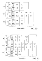
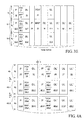
- FIGS. 3A to 3E are diagrams of exemplary frame structures according to the present invention.
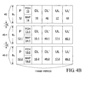
- FIGS. 4A to 4C are diagrams of other exemplary frame structures according to the present invention.
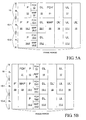
- FIGS. 5A and 5B are diagrams of still other exemplary frame structures according to the present invention.
- FIG. 6 is a flow diagram-illustrating an exemplary method of receiving a frame according to the present invention.
- FIG. 1 is a schematic diagram illustrating a communication system 100 according to an example of the present invention.
- the communication system 100 may include a base station 3, a relay station 4, first mobile stations 1-1, 1-2 and 1-3 for communication in a legacy standard and a second mobile station 2 for communication in a new standard backward compatible with the legacy standard.
- the base station 3 may generate a frame comprising sub-frames F1-1, F1-2 and F1-3.
- Each of the sub-frames F1-1, F1-2 and F2-3 may be transmitted using, for example, one third of the channel bandwidth available for the communication system 100.
- the sub-frames F1-2 and F1-3 may be transmitted to the first mobile stations 1-2 and 1-3, respectively, while the sub-frame F1-1 may be transmitted from the base station 3 via the relay station 4 to the first mobile station 1-1.
- a frame F2 may be generated by the base station 3 for the second mobile station 3.
- the frame F2 in one example may use the whole channel bandwidth of the communication system 100, and in another example may use a partial bandwidth.
- the communication system 100 is able to support communications in both of a new standard and a legacy standard.
- a new system or standard and a legacy system or standard may coexist in a communication network.
- the new standard may be backward compatible with the legacy standard.
- backward compatibility may include that a new terminal or subscriber station using a new standard may operate in a conventional network without significant impact on the performance and operation of terminals or stations relative to the conventional network.
- backward compatibility may include that a legacy terminal or subscriber station using a conventional standard may operate in a new network without significant impact on the performance and operation of terminals or stations relative to the new network.
- a "new” system or standard may refer to an “updated,” “evolved” or “next-generation” system or standard, while a “legacy” system or standard may refer to an “old” or “current” system or standard.
- a “new” standard may be a standard that is in use as of the date of the filing of this application
- a “legacy” standard may be a standard that is in use prior to the date of the filing of this application and may be still in use for some time after the-filing of this application.
- FIG. 2 is block diagram illustrating a module 110 for constructing a frame according to an example of the present invention.
- the module 110 may include a first frame generator 102, a second frame generator 104 and a frame constructor 106.
- the first frame generator 102 may be configured to generate a first portion of the frame for a first set of uplink and downlink data in order for communication in a first communication standard.
- the second frame generator 104 may be configured to generate a second portion of the frame for a second set of uplink and downlink data in order for communication in a second communication standard.
- the first communication standard may be a legacy standard such as the IEEE standard 802.16e
- the second communication standard may be a new standard such as the IEEE standard 802.16m.
- the frame constructor 106 may be configured to generate the frame, based on the first portion of the frame from the first frame generator 102 and the second portion of the frame from the second frame generator 104.
- the module 110 may be implemented in hardware or software.
- the module 110 may be integrated in a processor chip of an access station, for example, a base station such as the base station 3 or a relay station such as the relay station 4 illustrated in FIG. 1 .
- the module 110 may include executable programs or applications installed in a processor of the access station.
- the module 110 may be electrically coupled with a transmitting module 108, which may be configured to transmit a frame from the frame constructor 106 to a receiving module (not shown).
- the transmitting module 108 may be capable of transmitting data in subcarriers in different radio frequency channels in, for example, an OFDMA system. Examples of frame structures will be discussed below.
- FIGS. 3A to 3E are diagrams of exemplary frame structures according to the present invention.
- the frame may be transmitted in a frame period in contiguous bands 10, 10-1 and 10-2 having bandwidths B 1 , B 2 and B 3 , respectively.
- Each of the bands 10, 10-1 and 10-2 in the present example may be available for communication in the legacy standard, while a whole band composed of the bands 10, 10-1 and 10-2 may be available for communication in the new standard.
- the number of bands in a frame may not be limited to three as in the present example. Skilled persons in the art will understand that two or four or more than four bands may also be possible to suit different applications.
- the first portion of the frame may include a first preamble field, a first control field and first data fields.
- the second portion of the frame may include a second preamble field, a second control field and second data fields.
- the first portion of data for transmission in the legacy standard may include preambles 12, 12-1 and 12-2 in the first preamble field, frame control headers (FCH) 13, 13-1 and 13-2 and maps (MAP) 14, 14-1 and 14-2 in the first control field, and downlink data "DL" 15, 15-1 and 15-2, and uplink data "UL" 17, 17-1 and 17-2 in the first data fields.
- the second portion of data for transmission in the new standard may include downlink data "DL"' 16 and uplink data "UL”' 18 in the second data fields.
- the preamble 12, FCH 13, MAP 14, DL 15 and UL 17 may be transmitted in the band 10 via a first channel
- the preamble 12-1, FCH 13-1, MAP 14-1, DL 15-1 and UL 17-1 may be transmitted in the band 10-1 via a second channel
- the preamble 12-2, FCH 13-2, MAP 14-2, DL 15-2 and UL 17-2 may be transmitted in the band 10-2 via a third channel.
- the bandwidth for data transmission in the new standard may be greater than that for data transmission in the legacy standard.
- the second portion of data-DL' 16 and UL' 18 may be transmitted in the whole band having a bandwidth equal to B 1 + B 2 + B 3 .
- the preambles 12, 12-1 and 12-2 may include information on synchronization and may be used to transmit a synchronization signal for synchronization acquisition in a transmission/reception duration.
- the FCHs 13,13-1 and 13-2 may include information on sub-channels, ranging and a modulation or encoding method.
- the MAPs 14, 14-1 and 14-2 may include information on the locations of the first and second portions of data. Taking the band 10 as an example, the preamble 12 may include first synchronization information for the DL 15 and UL 17, the FCH 13 may include information about demodulation or decoding of MAP 14, and the MAP 14 may include information on the locations of DL 15 and UL 17 in the frame.
- the preamble 12-1 may include first synchronization information for the DL 15-1 and UL 17-1
- the FCH 13-1 may include information about demodulation or decoding of MAP 14-1
- the MAP 14-1 may include information on the locations of DL 15-1 and UL 17-1 in the frame.
- the preamble 12-1 may include first synchronization information for the DL 15-2 and UL 17-2
- the FCH 13-2 may include information about demodulation or decoding of MAP 14-2
- the MAP 14-2 may include information on the locations of DL 15-2 and UL 17-2 in the frame.
- At least one of the preamble 12, 12-1 or 12-2 may include second synchronization information for the second portion of data DL' 16 and UL' 18, and at least one of the MAP 14, 14-1 or 14-2 may include information on the locations of the DL' 16 and UL' 18 in the frame.
- the FCHs 13, 13-1 and 13-2 and the MAPs 14, 14-1 and 14-2 may be transmitted before the first and second portions of data. Moreover, the FCHs 13, 13-1 and 13-2 and the MAPs 14, 14-1 and 14-2 may be transmitted or received at the same time.
- a control filed may include but is not limited to FCHs and MAPs, and other arrangements of the FCHs and MAPs may be possible to suit different applications.
- the frame structure may be similar to that described and illustrated with reference to FIG. 3C except that, for example, a second preamble field and a second control field may be provided.
- a preamble 20 in the second preamble field, and FCH' 21 and MAP' 22 in the second control field may be added.
- the preamble 20 may include second synchronization information for the second portion of data DL' 16 and UL' 18, the FCH' 21 may include information about the demodulation or decoding of MAP' 22, and the MAP' 22 may include information on the locations of the DL' 16 and UL' 18 in the frame.
- the frame structure may be similar to that described and illustrated with reference to FIG. 3A except that, for example, each of the first and second data fields forms an integral portion in the frame.
- the uplink data UL 17, 17-1, 17-2 may be positioned in front of the DL' 16. Accordingly, the first portion of data may be transmitted before the second portion of data.
- the first portion of data is arranged in one frame zone, while the second portion of data is arranged in another frame zone of the frame.
- the frame structure may be similar to that described and illustrated with reference to FIG. 3B except that, for example, each of the first and second portions of the frame forms an integral portion in the frame.
- the uplink data UL 17, 17-1, 17-2 may be positioned in front of the preamble 20. Accordingly, the first portion of data may be transmitted before the second portion of data.
- the first portion of data is arranged in one frame zone, while the second portion of data is arranged in another frame zone of the frame.
- the frame structure may be similar to that described and illustrated with reference to FIG. 3B except that, for example, additional second data fields may be added for downlink data DL' 16-1 and uplink data UL' 18-1. Accordingly, the frame may be used to transmit multiple pairs of data, i.e., a first data pair DL' 16 and UL' 18 and a second data pair DL' 16-1 and UL' 18-1, in the new standard using the whole band.
- FIGS. 4A to 4C are diagrams of other exemplary frame structures according to the present invention.
- the frame structure may be similar to that described and illustrated with reference to FIG. 3B except, for example, bands 40, 40-1 and 40-2.
- the bands 40, 40-1 and 40-2 are discontiguous and may be separated by unused bands UB 1 and UB 2 .
- a second preamble field including second preambles 42, 42-1 and 42-2 may be transmitted after a period of time "UT.”
- Downlink data DL' 46, 46-1 and 46-2 and uplink data UL' 48, 48-1 and 48-2 may be transmitted to a single mobile station or a same user in the bands B 1 , B 2 and B 3 , respectively.
- one of the second preambles 42, 42-1 and 42-2 may include synchronization information for the transmission of DL' 46, 46-1, 46-2 and UL' 48, 48-1, 48-2.
- one of second control fields related to the one preamble may be decoded to identify the locations of DL' 46, 46-1, 46-2 and UL' 48, 48-1 and 48-2.
- the second preambles 42, 42-1 and 42-2 may include synchronization information for the transmission of their respective downlink data DL' and uplink data UL'.
- the second control fields FCHs 43, 43-1, 43-2 and MAPs 44, 44-1, 44-2 may be decoded to identify the locations of their respective DL' and UL'.
- the frame structure may be similar to that described and illustrated with reference to FIG. 4A except that, for example, the second preamble field and the second control field may be eliminated.
- one of the first preambles 12, 12-1 and 12-2 may include synchronization information for the transmission ofDL' 46,46-1, 46-2-and UL' 48, 48-1, 48-2.
- one of the first control fields related to the one preamble may be decoded to identify the locations of DL' 46, 46-1, 46-2 and UL' 48, 48-1 and 48-2.
- the first preambles 12, 12-1 and 12-2 may include synchronization information for the transmission of their respective downlink data DL' and uplink data UL'.
- the first control fields FCHs 13, 13-1, 13-2 and MAPs 14, 14-1, 14-2 may be decoded to identify-the locations of their respective DL' and UL'.
- the frame structure may be similar to that described and illustrated with reference to FIG. 4A except that, for example, the second preamble field may be positioned in front of the first preamble field.
- FIGS. 5A and 5B are diagrams of still other exemplary frame structures according to the present invention.
- the frame structure may be similar to that described and illustrated with reference to FIG. 3B except that, for example, the second preamble field may be positioned in front of the first preamble field.
- a frame may be provided with one first preamble field.
- the second preamble field may not be provided in each frame. In one example according to the present invention, approximately every two frames may be provided with one second preamble field.
- the frame structure may be similar to that described and illustrated with reference to FIG. 5A except that, for example, the second preamble field and the second control field may be positioned in front of the first preamble field.
- FIG. 6 is a flow diagram illustrating an exemplary method of receiving a frame according to the present invention.
- the frame may have a frame structure similar to one described and illustrated in FIGS. 3 to 6 .
- a first mobile station such as the first mobile station 1-1, 1-2 or 1-3 illustrated in FIG. 1 may perform a preamble cell search in the wireless communication system 100.
- a legacy preamble for communication in the legacy standard may be detected by the first mobile station.
- a legacy FCH/MAP related to the legacy preamble may be decoded and then a data zone may be identified.
- a second mobile station such as the second mobile station 2 illustrated in FIG. 1 , to identify a data zone, the method illustrated in FIG. 6 may be used.
- the second mobile station may perform a first preamble cell search for a first preamble that supports communication in the new standard.
- the i-th band may be similar to one of the contiguous bands 10, 10-1 and 10-2 illustrated in, for example, FIG. 3B while the first preamble may be similar to the preamble 20 in FIG. 4B .
- the first preamble may be transmitted in a j-th band having a bandwidth B j in the L bands and the j-th band may-individually-serve communication in both the legacy and new standards.
- the j-th band may be similar to one of the discontiguous bands 40, 40-1 and 40-2 illustrated in, for example, FIG. 4A while the first preamble may be similar to one of the preambles 40, 40-1 and 40-2 in FIG. 4B .
- a first MAP may be identified based on a preamble index in the first preamble and the first MAP may be decoded so as to identify a data zone in a frame to which the first preamble is related.
- the data zone may then be decoded at step 604.
- a second preamble cell search for a second preamble that supports communication in the legacy standard may be performed.
- a second MAP may be identified based on a second preamble index in the second preamble and the second MAP may be decoded so as to identify a data zone in a frame to which the second preamble is related.
- the data zone may then be decoded at step 604.
Landscapes
- Engineering & Computer Science (AREA)
- Signal Processing (AREA)
- Computer Networks & Wireless Communication (AREA)
- Mobile Radio Communication Systems (AREA)
- Communication Control (AREA)
Abstract
Description
- This application claims the benefit of
U.S. Provisional Application No. 60/929,798, filed July 12, 2007 - The present invention relates to communication systems. More particularly, the present invention relates to methods and modules for constructing a frame structure in a communication system.
- Orthogonal Frequency Division Multiple Access (OFDMA) is a multiple access scheme for transmitting data in different subcarriers in a channel, wherein the data may come from different users and may be transmitted in disjoint subsets of sub-channels in a transmission bandwidth. The orthogonality property among the subcarriers may allow simultaneous transmission of data from different users without interference from one other. The multiple access scheme of the OFDMA may generally be applied in various communication systems, such as those defined in IEEE standard 802.16e ("legacy system" hereafter) and IEEE standard 802.16m ("new system" hereafter). The new system defined in the IEEE standard 802.16m may be required to provide enhanced spectrum efficiency, higher speed tolerance and full backward compatibility with the legacy system defined in the IEEE standard 802.16e.
- Since a communication system, either legacy or new, may have an individual frame structure for data transmission, and the legacy and new systems may operate on the same radio frequency (RF) carrier in the same channel bandwidth, it may be desirable to have a new frame structure for the legacy and new systems to coexist in a communication network while enhancing spectrum efficiency and speed tolerance.
- Examples of the present invention may provide a module for constructing a frame for communication in a communication system that supports a new standard and a legacy standard, the new standard being backward compatible with the legacy standard, the module comprising a first frame generator configured to generate a first portion of the frame, the first portion of the frame to support a first set of data to be transmitted in the legacy standard in each of a number of first bands, a second frame generator configured to generate a second portion of the frame, the second portion of the frame to support a second set of data to be transmitted in the new standard in a second band composed of the first bands, and a frame constructor configured to construct the frame based on the first portion of the frame from the first frame generator and the second portion of the frame from the second frame generator.
- Some examples of the present invention may also provide a module for constructing a frame for communication in a communication system that supports a new standard and a legacy standard, the new standard being backward compatible with the legacy standard, the module comprising a first frame generator configured to generate at least one first frame zone for each of a number of first bands for transmission of a first set of data in the legacy standard using the each of the first bands, at least one of the first bands being discontiguous with the other of the first bands, a second frame generator configured to generate at least one second frame zone for each of the first bands for transmission of a second set of data in the new standard using a second band composed of the first bands, and a frame constructor configured to construct the frame based on the at least one first frame zone for each of the first bands from the first frame generator and the at least one second frame zone for each of the first bands from the second frame generator.
- Examples of the present invention may further provide a method for constructing a frame for communication in a communication system that supports a new standard and a legacy standard, the new standard being backward compatible with the legacy standard, the method comprising forming a first portion of the frame, the first portion of the frame to support a first set of data to be transmitted in the legacy standard in each of a number of first bands, forming a second portion of the frame, the second portion of the frame to support a second set of data to be transmitted in the new standard in a second band composed of the first bands, and constructing the frame based on the first portion of the frame from the first frame generator and the second portion of the frame from the second frame generator.
- Examples of the present invention may also provide a method of communication in a communication system that supports a new standard and a legacy standard, the new standard being backward compatible with the legacy standard, the method comprising performing a first preamble cell search for a first preamble that supports communication in the new standard, decoding a first control field in a first frame related to the first preamble to identify the location of a first data zone if the first preamble is detected, performing a second preamble cell search for a second preamble that supports communication in the legacy standard if the first preamble is not detected, and decoding a second control field in a second frame related to the second preamble to identify the location of a second data zone.
- Additional features and advantages of the present invention will be set forth in part in the description which follows, and in part will be obvious from the description, or may be learned by practice of the invention. The features and advantages of the invention will be realized and attained by means of the elements and combinations particularly pointed out in the appended claims.
- It is to be understood that-both the foregoing general description and the following detailed description are exemplary and explanatory only and are not restrictive of the invention, as claimed.
- The foregoing summary, as well as the following detailed description-of the invention, will be better understood when read in conjunction with the appended drawings. For the purpose of illustrating the invention, there are shown in the drawings examples which are presently preferred. It should-be understood, however, that the invention is not limited to the precise arrangements and instrumentalities shown.
- In the drawings:
-
FIG. 1 is a schematic diagram illustrating a communication system according to an example of the present invention; -
FIG. 2 is a block diagram illustrating a module for constructing a frame according to an example of the present invention; -
FIGS. 3A to 3E are diagrams of exemplary frame structures according to the present invention; -
FIGS. 4A to 4C are diagrams of other exemplary frame structures according to the present invention; -
FIGS. 5A and 5B are diagrams of still other exemplary frame structures according to the present invention; and -
FIG. 6 is a flow diagram-illustrating an exemplary method of receiving a frame according to the present invention. - Reference will now be made in detail to the present examples of the invention, examples of which are illustrated in the accompanying drawings. Wherever possible, the same reference numbers will be used throughout the drawings to refer to the same or like parts.
-
FIG. 1 is a schematic diagram illustrating acommunication system 100 according to an example of the present invention. Thecommunication system 100, for example, an orthogonal frequency division multiple access (OFDMA) system, may include abase station 3, arelay station 4, first mobile stations 1-1, 1-2 and 1-3 for communication in a legacy standard and a secondmobile station 2 for communication in a new standard backward compatible with the legacy standard. Thebase station 3 may generate a frame comprising sub-frames F1-1, F1-2 and F1-3. Each of the sub-frames F1-1, F1-2 and F2-3 may be transmitted using, for example, one third of the channel bandwidth available for thecommunication system 100. The sub-frames F1-2 and F1-3 may be transmitted to the first mobile stations 1-2 and 1-3, respectively, while the sub-frame F1-1 may be transmitted from thebase station 3 via therelay station 4 to the first mobile station 1-1. Moreover, a frame F2 may be generated by thebase station 3 for the secondmobile station 3. The frame F2 in one example may use the whole channel bandwidth of thecommunication system 100, and in another example may use a partial bandwidth. - The
communication system 100 is able to support communications in both of a new standard and a legacy standard. With the rapid development in communication technologies, a new system or standard and a legacy system or standard may coexist in a communication network. In this case, the new standard may be backward compatible with the legacy standard. In one example according to the present invention, backward compatibility may include that a new terminal or subscriber station using a new standard may operate in a conventional network without significant impact on the performance and operation of terminals or stations relative to the conventional network. In other examples, backward compatibility may include that a legacy terminal or subscriber station using a conventional standard may operate in a new network without significant impact on the performance and operation of terminals or stations relative to the new network. Throughout the specification, a "new" system or standard may refer to an "updated," "evolved" or "next-generation" system or standard, while a "legacy" system or standard may refer to an "old" or "current" system or standard. For example, a "new" standard may be a standard that is in use as of the date of the filing of this application, and a "legacy" standard may be a standard that is in use prior to the date of the filing of this application and may be still in use for some time after the-filing of this application. -
FIG. 2 is block diagram illustrating amodule 110 for constructing a frame according to an example of the present invention. Referring toFIG. 2 , themodule 110 may include afirst frame generator 102, asecond frame generator 104 and aframe constructor 106. Thefirst frame generator 102 may be configured to generate a first portion of the frame for a first set of uplink and downlink data in order for communication in a first communication standard. Thesecond frame generator 104 may be configured to generate a second portion of the frame for a second set of uplink and downlink data in order for communication in a second communication standard. In one example, the first communication standard may be a legacy standard such as the IEEE standard 802.16e, while the second communication standard may be a new standard such as the IEEE standard 802.16m. Theframe constructor 106 may be configured to generate the frame, based on the first portion of the frame from thefirst frame generator 102 and the second portion of the frame from thesecond frame generator 104. - The
module 110, including thefirst frame generator 102, thesecond frame generator 104 and theframe constructor 106, may be implemented in hardware or software. For example, if implemented in hardware, themodule 110 may be integrated in a processor chip of an access station, for example, a base station such as thebase station 3 or a relay station such as therelay station 4 illustrated inFIG. 1 . Alternatively, if implemented in software, themodule 110 may include executable programs or applications installed in a processor of the access station. - Furthermore, the
module 110 may be electrically coupled with atransmitting module 108, which may be configured to transmit a frame from theframe constructor 106 to a receiving module (not shown). In one example, the transmittingmodule 108 may be capable of transmitting data in subcarriers in different radio frequency channels in, for example, an OFDMA system. Examples of frame structures will be discussed below. -
FIGS. 3A to 3E are diagrams of exemplary frame structures according to the present invention. Referring toFIG. 3A , the frame may be transmitted in a frame period incontiguous bands 10, 10-1 and 10-2 having bandwidths B1, B2 and B3, respectively. Each of thebands 10, 10-1 and 10-2 in the present example may be available for communication in the legacy standard, while a whole band composed of thebands 10, 10-1 and 10-2 may be available for communication in the new standard. Furthermore, the number of bands in a frame may not be limited to three as in the present example. Skilled persons in the art will understand that two or four or more than four bands may also be possible to suit different applications. - The first portion of the frame may include a first preamble field, a first control field and first data fields. Similarly, the second portion of the frame may include a second preamble field, a second control field and second data fields. In the present example, in the first portion of the frame, the first portion of data for transmission in the legacy standard may include
preambles 12, 12-1 and 12-2 in the first preamble field, frame control headers (FCH) 13, 13-1 and 13-2 and maps (MAP) 14, 14-1 and 14-2 in the first control field, and downlink data "DL" 15, 15-1 and 15-2, and uplink data "UL" 17, 17-1 and 17-2 in the first data fields. Furthermore, in the second portion of the frame, the second portion of data for transmission in the new standard may include downlink data "DL"' 16 and uplink data "UL"' 18 in the second data fields. Moreover, thepreamble 12,FCH 13,MAP 14,DL 15 andUL 17 may be transmitted in theband 10 via a first channel, the preamble 12-1, FCH 13-1, MAP 14-1, DL 15-1 and UL 17-1 may be transmitted in the band 10-1 via a second channel, and the preamble 12-2, FCH 13-2, MAP 14-2, DL 15-2 and UL 17-2 may be transmitted in the band 10-2 via a third channel. Generally, the bandwidth for data transmission in the new standard may be greater than that for data transmission in the legacy standard. In the present example, the second portion of data-DL' 16 and UL' 18 may be transmitted in the whole band having a bandwidth equal to B1 + B2 + B3. - In the frame, the
preambles 12, 12-1 and 12-2 may include information on synchronization and may be used to transmit a synchronization signal for synchronization acquisition in a transmission/reception duration. Furthermore, theFCHs 13,13-1 and 13-2 may include information on sub-channels, ranging and a modulation or encoding method. Moreover, theMAPs 14, 14-1 and 14-2 may include information on the locations of the first and second portions of data. Taking theband 10 as an example, thepreamble 12 may include first synchronization information for theDL 15 andUL 17, theFCH 13 may include information about demodulation or decoding ofMAP 14, and theMAP 14 may include information on the locations ofDL 15 andUL 17 in the frame. Similarly, for the band 10-1, the preamble 12-1 may include first synchronization information for the DL 15-1 and UL 17-1, the FCH 13-1 may include information about demodulation or decoding of MAP 14-1, and the MAP 14-1 may include information on the locations of DL 15-1 and UL 17-1 in the frame. Similarly, for the band 10-2, the preamble 12-1 may include first synchronization information for the DL 15-2 and UL 17-2, the FCH 13-2 may include information about demodulation or decoding of MAP 14-2, and the MAP 14-2 may include information on the locations of DL 15-2 and UL 17-2 in the frame. - Furthermore, at least one of the
preamble 12, 12-1 or 12-2 may include second synchronization information for the second portion of data DL' 16 and UL' 18, and at least one of theMAP 14, 14-1 or 14-2 may include information on the locations of the DL' 16 and UL' 18 in the frame. - In the present example, the
FCHs 13, 13-1 and 13-2 and theMAPs 14, 14-1 and 14-2 may be transmitted before the first and second portions of data. Moreover, theFCHs 13, 13-1 and 13-2 and theMAPs 14, 14-1 and 14-2 may be transmitted or received at the same time. Those skilled in the art can easily understand that a control filed may include but is not limited to FCHs and MAPs, and other arrangements of the FCHs and MAPs may be possible to suit different applications. - Referring to
FIG. 3B , the frame structure may be similar to that described and illustrated with reference toFIG. 3C except that, for example, a second preamble field and a second control field may be provided. Specifically, apreamble 20 in the second preamble field, and FCH' 21 and MAP' 22 in the second control field may be added. Furthermore, thepreamble 20 may include second synchronization information for the second portion of data DL' 16 and UL' 18, the FCH' 21 may include information about the demodulation or decoding of MAP' 22, and the MAP' 22 may include information on the locations of the DL' 16 and UL' 18 in the frame. - Referring to
FIG. 3C , the frame structure may be similar to that described and illustrated with reference toFIG. 3A except that, for example, each of the first and second data fields forms an integral portion in the frame. Specifically, theuplink data UL 17, 17-1, 17-2 may be positioned in front of the DL' 16. Accordingly, the first portion of data may be transmitted before the second portion of data. Unlike the first or second portion of data illustrated inFIGS. 3A and 3B that is allocated in separate frame zones of the frame, in the present example, the first portion of data is arranged in one frame zone, while the second portion of data is arranged in another frame zone of the frame. - Referring to
FIG. 3D , the frame structure may be similar to that described and illustrated with reference toFIG. 3B except that, for example, each of the first and second portions of the frame forms an integral portion in the frame. Specifically, theuplink data UL 17, 17-1, 17-2 may be positioned in front of thepreamble 20. Accordingly, the first portion of data may be transmitted before the second portion of data. In the present example, the first portion of data is arranged in one frame zone, while the second portion of data is arranged in another frame zone of the frame. - Referring to
FIG. 3E , the frame structure may be similar to that described and illustrated with reference toFIG. 3B except that, for example, additional second data fields may be added for downlink data DL' 16-1 and uplink data UL' 18-1. Accordingly, the frame may be used to transmit multiple pairs of data, i.e., a first data pair DL' 16 and UL' 18 and a second data pair DL' 16-1 and UL' 18-1, in the new standard using the whole band. -
FIGS. 4A to 4C are diagrams of other exemplary frame structures according to the present invention. Referring toFIG. 4A , the frame structure may be similar to that described and illustrated with reference toFIG. 3B except, for example,bands 40, 40-1 and 40-2. Specifically, unlike thecontiguous bands 10, 10-1 and 10-2 illustrated inFIG. 3B , thebands 40, 40-1 and 40-2 are discontiguous and may be separated by unused bands UB1 and UB2. Furthermore, a second preamble field includingsecond preambles 42, 42-1 and 42-2 may be transmitted after a period of time "UT." Downlink data DL' 46, 46-1 and 46-2 and uplink data UL' 48, 48-1 and 48-2 may be transmitted to a single mobile station or a same user in the bands B1, B2 and B3, respectively. In one example, one of thesecond preambles 42, 42-1 and 42-2 may include synchronization information for the transmission of DL' 46, 46-1, 46-2 and UL' 48, 48-1, 48-2. In this case, one of second control fields related to the one preamble may be decoded to identify the locations of DL' 46, 46-1, 46-2 and UL' 48, 48-1 and 48-2. In another example, thesecond preambles 42, 42-1 and 42-2 may include synchronization information for the transmission of their respective downlink data DL' and uplink data UL'. In this case, the second control fieldsFCHs 43, 43-1, 43-2 andMAPs 44, 44-1, 44-2 may be decoded to identify the locations of their respective DL' and UL'. - Referring to
FIG. 4B , the frame structure may be similar to that described and illustrated with reference toFIG. 4A except that, for example, the second preamble field and the second control field may be eliminated. In one example, one of thefirst preambles 12, 12-1 and 12-2 may include synchronization information for the transmission ofDL' 46,46-1, 46-2-and UL' 48, 48-1, 48-2. In this case, one of the first control fields related to the one preamble may be decoded to identify the locations of DL' 46, 46-1, 46-2 and UL' 48, 48-1 and 48-2. In another example, thefirst preambles 12, 12-1 and 12-2 may include synchronization information for the transmission of their respective downlink data DL' and uplink data UL'. In this case, the firstcontrol fields FCHs 13, 13-1, 13-2 andMAPs 14, 14-1, 14-2 may be decoded to identify-the locations of their respective DL' and UL'. - Referring to
FIG. 4C , the frame structure may be similar to that described and illustrated with reference toFIG. 4A except that, for example, the second preamble field may be positioned in front of the first preamble field. -
FIGS. 5A and 5B are diagrams of still other exemplary frame structures according to the present invention. Referring toFIG. 5A , the frame structure may be similar to that described and illustrated with reference toFIG. 3B except that, for example, the second preamble field may be positioned in front of the first preamble field. Generally, a frame may be provided with one first preamble field. The second preamble field, however, may not be provided in each frame. In one example according to the present invention, approximately every two frames may be provided with one second preamble field. - Referring to
FIG. 5B , the frame structure may be similar to that described and illustrated with reference toFIG. 5A except that, for example, the second preamble field and the second control field may be positioned in front of the first preamble field. -
FIG. 6 is a flow diagram illustrating an exemplary method of receiving a frame according to the present invention. The frame may have a frame structure similar to one described and illustrated inFIGS. 3 to 6 . A first mobile station such as the first mobile station 1-1, 1-2 or 1-3 illustrated inFIG. 1 may perform a preamble cell search in thewireless communication system 100. A legacy preamble for communication in the legacy standard may be detected by the first mobile station. Next, a legacy FCH/MAP related to the legacy preamble may be decoded and then a data zone may be identified. As to a second mobile station such as the secondmobile station 2 illustrated inFIG. 1 , to identify a data zone, the method illustrated inFIG. 6 may be used. Referring toFIG. 6 , atstep 601, the second mobile station may perform a first preamble cell search for a first preamble that supports communication in the new standard. - In one example, the first preamble may be transmitted in a band having a bandwidth

contiguous bands 10, 10-1 and 10-2 illustrated in, for example,FIG. 3B while the first preamble may be similar to thepreamble 20 inFIG. 4B . - In another example, the first preamble may be transmitted in a j-th band having a bandwidth Bj in the L bands and the j-th band may-individually-serve communication in both the legacy and new standards. In this case, the j-th band may be similar to one of the
discontiguous bands 40, 40-1 and 40-2 illustrated in, for example,FIG. 4A while the first preamble may be similar to one of thepreambles 40, 40-1 and 40-2 inFIG. 4B . - - If at step 602 a such first preamble is detected, at
step 603, a first MAP may be identified based on a preamble index in the first preamble and the first MAP may be decoded so as to identify a data zone in a frame to which the first preamble is related. The data zone may then be decoded at step 604. - If at
step 602 no such first preamble is detected, then atstep 605, a second preamble cell search for a second preamble that supports communication in the legacy standard may be performed. Subsequently, atstep 606, a second MAP may be identified based on a second preamble index in the second preamble and the second MAP may be decoded so as to identify a data zone in a frame to which the second preamble is related. The data zone may then be decoded at step 604. - It will be appreciated by those skilled in the art that changes could be made to the examples described above without departing from the broad inventive concept thereof. It is understood, therefore, that this invention is not limited to the particular examples disclosed, but it is intended to cover modifications within the spirit and scope of the present invention as defined by the appended claims.
- Further, in describing representative examples of the present invention, the specification may have presented the method and/or process of the present invention as a particular sequence of steps. However, to the extent that the method or process does not rely on the particular order of steps set forth herein, the method or process should not be limited to the particular sequence of steps described. As one of ordinary skill in the art would appreciate, other sequences of steps may be possible. Therefore, the particular order of the steps set forth in the specification should not be construed as limitations on the claims. In addition, the claims directed to the method and/or process of the present invention should not be limited to the performance of their steps in the order written, and one skilled in the art can readily appreciate that the sequences may be varied and still remain within the spirit and scope of the present invention.
The features disclosed in the foregoing description, in the claims and/or in the acccnpanying drawings may, both separately and in any combination thereof, be material for realising the invention in diverse forms thereof.
Claims (37)
- A module for constructing a frame for communication in a communication system that supports a new standard and a legacy standard, the new standard being backward compatible with the legacy standard, the module comprising:a first frame generator configured to generate a first portion of the frame, the first portion of the frame to support a first set of data to be transmitted in the legacy standard in each of a number of first bands;a second frame generator configured to generate a second portion of the frame, the second portion of the frame to support a second set of data to be transmitted in the new standard in a second band composed of the first bands; anda frame constructor configured to construct the frame based on the first portion of the frame from the first frame generator and the second portion of the frame from the second frame generator.
- The module of claim 1, wherein the first portion of the frame includes a first preamble field, a first control field and at least one first data field, and the second portion of the frame includes at least one second data field.
- The module of claim 2, wherein the first set of data includes a first preamble in the first preamble field, a first frame control header (FCH) and a first map (MAP) in the first control field, and first downlink data and first uplink data in the at least one first data field.
- The module of claim 2, wherein the second set of data includes second downlink data and second uplink data in the at least one second data field.
- The module of claim 2, wherein one of the at least one second data field is interleaved with the at least one first data field in the frame.
- The module of claim 2, wherein the at least one first data field is arranged in one integral zone of the frame and the at least one second data field is arranged in another integral zone of the frame.
- The module of claim 2, wherein in each of the first bands the first control field includes information on the location of the at least one first data field in the frame.
- The module of claim 2, wherein in one of the first bands the first control field includes information on the location of the at least one second data field in the frame.
- The module of claim 2, wherein the second portion of the frame further includes a second preamble field and a second control field.
- The module of claim 9, wherein the second control field includes information on the location of the at least one second data field in the frame.
- The module of claim 9, wherein the second preamble field is positioned in front of the first preamble field in the frame.
- The module of claim 1, wherein at least one of the first bands is separated from others by an unused band:
- A module for constructing a frame for communication in a communication system that supports a new standard and a legacy standard, the new standard being backward compatible with the legacy standard, the module comprising:a first frame generator configured to generate at least one first frame zone for each of a number of first bands for transmission of a first set of data in the legacy standard using the each of the first bands, at least one of the first bands being discontiguous with the other of the first bands;a second frame generator configured to generate at least one second frame zone for each of the first bands for transmission of a second set of data in the new standard using a second band composed of the first bands; anda frame constructor configured to construct the frame based on the at least one first frame zone for each of the first bands from the first frame generator and the at least one second frame zone for each of the first bands from the second frame generator.
- The module of claim 13, wherein the at least one first frame zone includes a first preamble field, a first control field and at least one first data field, and the at least one second frame zone includes at least one second data field.
- The module of claim 14, wherein the first set of data includes a first preamble in the first preamble field, a first frame control header (FCH) and a first map (MAP) in the first control field, and first downlink data and first uplink data in the at least one first data field.
- The module of claim 14, wherein the second set of data includes second downlink data and second uplink data in the at least one second data field.
- The module of claim 14, wherein one of the at least one second data field is interleaved with the at least one first data field in the frame.
- The module of claim 14, wherein in each of the first bands the first control field includes information on the location of the at least one first data field in the frame.
- The module of claim 14, wherein in one of the first bands the first control field includes information on the location of the at least one second data field in the frame.
- The module of claim 14, wherein the at least one-second frame zone further includes a second preamble field and a second control field.
- The module of claim 20, wherein the second control field includes information on the location of the at least one second data field in the frame.
- The module of claim 20, wherein the second preamble field is positioned in front of the first preamble field in the frame.
- A method for constructing a frame for communication in a communication system that supports a new standard and a legacy standard, the new standard being backward compatible with the legacy standard, the method comprising:forming a first portion of the frame, the first portion of the frame to support a first set of data to be transmitted in the legacy standard in each of a number of first bands;forming a second portion of the frame, the second portion of the frame to support a second set of data to be transmitted in the new standard in a second band composed of the first bands; andconstructing the frame based on the first portion of the frame from a first frame generator and the second portion of the frame from a second frame generator.
- The method of claim 23 further comprising providing the first portion of the frame with a first preamble field, a first control field and at least one first data field, and providing the second portion of the frame with at least one second data field.
- The method of claim 24 further comprising providing the first set of data with a first preamble in the first preamble field, a first frame control header (FCH) and a first map (MAP) in the first control field, and first downlink data and first uplink data in the at least one first data field.
- The method of claim 24 further comprising providing the second set of data with second downlink data and second uplink data in the at least one second data field.
- The method of claim 24 further comprising inter leaving one of the at least one second data field with the at least one first data field in the frame.
- The method of claim 24 further comprising arranging the at least one first data field in one integral zone of the frame and arranging the at least one second data field in another integral zone of the frame.
- The method of claim 24 further comprising decoding in each of the first bands the first control field to identify the location of the at least one first data field in the frame.
- The method of claim 24 further comprising decoding in one of the first bands the first control field to identify the location of the at least one second data field in the frame.
- The method of claim 24 further comprising providing the second portion of the frame with a second preamble field and a second control field.
- The method of claim 31 further comprising decoding the second control field to identify the location of the at least one second data field in the frame.
- The method of claim 31 further comprising positioning the second preamble field in front of the first preamble field in the frame.
- The method of claim 23 further comprising separating at least one of the first bands from the other of the first bands by an unused band.
- A method of communication in a communication system that supports a new standard and a legacy standard, the new standard being backward compatible with the legacy standard, the method comprising:performing a first preamble cell search for a first preamble that supports communication in the new standard;decoding a first control field in a first frame related to the first preamble to identify the location of a first data zone if the first preamble is detected;performing a second preamble-cell search for a second preamble that supports communication in the legacy standard if the first preamble is not detected; anddecoding a second control field in a secondframe related to the second preamble to identify the location of a second data zone.
- The method of claim 35, wherein the first preamble is transmitted in a first band having a first bandwidth, and the second preamble is transmitted in at least one second band having a second bandwidth, the first bandwidth being equal to a sum of the second bandwidth of the at least one second band.
- The method of claim 35, wherein the first preamble is transmitted in a first band having a first bandwidth, and the second preamble is transmitted in at least one second band, the first bandwidth being equal to the bandwidth of one of the at least one second band.
Applications Claiming Priority (2)
| Application Number | Priority Date | Filing Date | Title |
|---|---|---|---|
| US92979807P | 2007-07-12 | 2007-07-12 | |
| US12/168,846 US8279812B2 (en) | 2007-07-12 | 2008-07-07 | Method and module for constructing a frame structure in communication systems |
Publications (2)
| Publication Number | Publication Date |
|---|---|
| EP2019528A2 true EP2019528A2 (en) | 2009-01-28 |
| EP2019528A3 EP2019528A3 (en) | 2014-08-06 |
Family
ID=40123495
Family Applications (1)
| Application Number | Title | Priority Date | Filing Date |
|---|---|---|---|
| EP08012444.9A Pending EP2019528A3 (en) | 2007-07-12 | 2008-07-09 | Method and module for constructing a frame structure in communication systems |
Country Status (1)
| Country | Link |
|---|---|
| EP (1) | EP2019528A3 (en) |
Cited By (4)
| Publication number | Priority date | Publication date | Assignee | Title |
|---|---|---|---|---|
| WO2009045151A3 (en) * | 2007-10-03 | 2009-05-28 | Ericsson Telefon Ab L M | Telecommunications frame structure accomodating differing formats |
| WO2009072962A1 (en) * | 2007-12-06 | 2009-06-11 | Telefonaktiebolaget L M Ericsson (Publ) | Interlacing wireless communication frames |
| EP2208287A4 (en) * | 2007-11-07 | 2010-12-22 | Ericsson Telefon Ab L M | Uplink radio frames apportioned for plural multiple access technologies |
| US8861549B2 (en) | 2007-11-05 | 2014-10-14 | Telefonaktiebolaget Lm Ericsson (Publ) | Multiple compatible OFDM systems with different bandwidths |
Family Cites Families (4)
| Publication number | Priority date | Publication date | Assignee | Title |
|---|---|---|---|---|
| US7269430B2 (en) * | 2003-11-24 | 2007-09-11 | Broadcom Corporation | Frame format for high data throughput wireless local area network transmissions |
| US7400643B2 (en) * | 2004-02-13 | 2008-07-15 | Broadcom Corporation | Transmission of wide bandwidth signals in a network having legacy devices |
| US7570619B2 (en) * | 2004-02-13 | 2009-08-04 | Broadcom Corporation | Long training sequence method and device for wireless communications |
| US8077592B2 (en) * | 2004-06-22 | 2011-12-13 | Intellectual Ventures I Llc | Packet processing systems and methods |
-
2008
- 2008-07-09 EP EP08012444.9A patent/EP2019528A3/en active Pending
Non-Patent Citations (1)
| Title |
|---|
| MARK CUDAK MOTOROLA MICHAEL WEBB BRN PHOENIX INC PHIL ORLIK MITSUBISHI ELECTRIC RESEARCH LABORATORIES AVI FREEDMAN HEXAGON SYSTEM: "Combined Draft IEEE 802.16m Requirements (For Information Only)", IEEE DRAFT; C80216M-07_058, IEEE-SA, PISCATAWAY, NJ USA, vol. 802.16m, 6 March 2007 (2007-03-06), pages 1 - 64, XP068000517, [retrieved on 20070306] * |
Cited By (8)
| Publication number | Priority date | Publication date | Assignee | Title |
|---|---|---|---|---|
| WO2009045151A3 (en) * | 2007-10-03 | 2009-05-28 | Ericsson Telefon Ab L M | Telecommunications frame structure accomodating differing formats |
| US8098623B2 (en) | 2007-10-03 | 2012-01-17 | Telefonaktiebolaget Lm Ericsson | Telecommunications frame structure accomodating differing formats |
| US8861549B2 (en) | 2007-11-05 | 2014-10-14 | Telefonaktiebolaget Lm Ericsson (Publ) | Multiple compatible OFDM systems with different bandwidths |
| EP2208287A4 (en) * | 2007-11-07 | 2010-12-22 | Ericsson Telefon Ab L M | Uplink radio frames apportioned for plural multiple access technologies |
| US8155701B2 (en) | 2007-11-07 | 2012-04-10 | Telefonaktiebolaget Lm Ericsson (Publ) | Uplink radio frames apportioned for plural multiple access technologies |
| WO2009072962A1 (en) * | 2007-12-06 | 2009-06-11 | Telefonaktiebolaget L M Ericsson (Publ) | Interlacing wireless communication frames |
| US8477697B2 (en) | 2007-12-06 | 2013-07-02 | Telefonaktiebolaget Lm Ericsson (Publ) | Interlacing wireless communication frames |
| US9100949B2 (en) | 2007-12-06 | 2015-08-04 | Telefonaktiebolaget L M Ericsson (Publ) | Interlacing wireless communication frames |
Also Published As
| Publication number | Publication date |
|---|---|
| EP2019528A3 (en) | 2014-08-06 |
Similar Documents
| Publication | Publication Date | Title |
|---|---|---|
| US8279812B2 (en) | Method and module for constructing a frame structure in communication systems | |
| US10827534B2 (en) | Initial access channel for scalable wireless mobile communication networks | |
| EP2161941B1 (en) | A method and device for pilot mapping in multiplexing mode of unicast and broadcast/multicast services | |
| CN110808825B (en) | Base station, user equipment and method thereof | |
| EP3488576B1 (en) | Symbol and subframe alignment in a wireless communication system | |
| EP0786890B1 (en) | Resource allocation in a multi-user, multicarrier mobile radio system | |
| KR101179627B1 (en) | Method And Apparatus For Allocating Demodulation Reference Signal | |
| EP3900417B1 (en) | Synchronization signal transmission | |
| JP2009533941A (en) | Reference signal allocation method in MIMO system {MethodforlocatingreferencingsignalinMIMOsystem} | |
| EP3442150B1 (en) | Information transmission method, receiving method, user equipment and base station | |
| US20120207239A1 (en) | Orthogonal Pilot Code Construction | |
| CN112564868A (en) | Signal sending and receiving method and terminal | |
| CN109787721A (en) | Method and device, tone hopping information configuration method and the device of Data duplication transmission | |
| CN106888472A (en) | Data transmission method and device | |
| US20100177726A1 (en) | Method and system for synchronization and cell identification within communication systems | |
| CN100589360C (en) | Method and system for processing reference symbols in OFDM system | |
| US20120093115A1 (en) | Method for mapping resources of broadcast control channel | |
| US8498232B2 (en) | Method of transmitting data in wireless communication system | |
| KR101667428B1 (en) | Preamble generation method and apparatus of station, data frmae generation method | |
| KR101391727B1 (en) | Apparatus and method for constructing a frame in a communication system | |
| CN102075948B (en) | Method and system for transmitting reference signs under generalized cell system structure | |
| CN101115269A (en) | Method, device and application for identifying cell identifier ID number | |
| US7801532B2 (en) | System and method for transmitting/receiving signal in a frequency overlay communication system | |
| CN121547871A (en) | A data transmission method and system | |
| CN121014188A (en) | Methods and devices for wireless communication |
Legal Events
| Date | Code | Title | Description |
|---|---|---|---|
| PUAI | Public reference made under article 153(3) epc to a published international application that has entered the european phase |
Free format text: ORIGINAL CODE: 0009012 |
|
| AK | Designated contracting states |
Kind code of ref document: A2 Designated state(s): AT BE BG CH CY CZ DE DK EE ES FI FR GB GR HR HU IE IS IT LI LT LU LV MC MT NL NO PL PT RO SE SI SK TR |
|
| AX | Request for extension of the european patent |
Extension state: AL BA MK RS |
|
| PUAL | Search report despatched |
Free format text: ORIGINAL CODE: 0009013 |
|
| AK | Designated contracting states |
Kind code of ref document: A3 Designated state(s): AT BE BG CH CY CZ DE DK EE ES FI FR GB GR HR HU IE IS IT LI LT LU LV MC MT NL NO PL PT RO SE SI SK TR |
|
| AX | Request for extension of the european patent |
Extension state: AL BA MK RS |
|
| RIC1 | Information provided on ipc code assigned before grant |
Ipc: H04L 27/26 20060101AFI20140702BHEP Ipc: H04L 5/00 20060101ALI20140702BHEP Ipc: H04W 88/06 20090101ALI20140702BHEP |
|
| 17P | Request for examination filed |
Effective date: 20150206 |
|
| RBV | Designated contracting states (corrected) |
Designated state(s): AT BE BG CH CY CZ DE DK EE ES FI FR GB GR HR HU IE IS IT LI LT LU LV MC MT NL NO PL PT RO SE SI SK TR |
|
| AKX | Designation fees paid |
Designated state(s): AT BE BG CH CY CZ DE DK EE ES FI FR GB GR HR HU IE IS IT LI LT LU LV MC MT NL NO PL PT RO SE SI SK TR |
|
| AXX | Extension fees paid |
Extension state: RS Extension state: AL Extension state: MK Extension state: BA |
|
| STAA | Information on the status of an ep patent application or granted ep patent |
Free format text: STATUS: EXAMINATION IS IN PROGRESS |
|
| 17Q | First examination report despatched |
Effective date: 20180403 |
|
| RAP1 | Party data changed (applicant data changed or rights of an application transferred) |
Owner name: SINO MATRIX TECHNOLOGY, INC. |
|
| RAP1 | Party data changed (applicant data changed or rights of an application transferred) |
Owner name: STC.UNM |
|
| GRAP | Despatch of communication of intention to grant a patent |
Free format text: ORIGINAL CODE: EPIDOSNIGR1 |
|
| STAA | Information on the status of an ep patent application or granted ep patent |
Free format text: STATUS: GRANT OF PATENT IS INTENDED |
|
| INTG | Intention to grant announced |
Effective date: 20260317 |