EP2019450A1 - Connector for coaxial cable - Google Patents
Connector for coaxial cable Download PDFInfo
- Publication number
- EP2019450A1 EP2019450A1 EP07113182A EP07113182A EP2019450A1 EP 2019450 A1 EP2019450 A1 EP 2019450A1 EP 07113182 A EP07113182 A EP 07113182A EP 07113182 A EP07113182 A EP 07113182A EP 2019450 A1 EP2019450 A1 EP 2019450A1
- Authority
- EP
- European Patent Office
- Prior art keywords
- coaxial cable
- housing
- conductive housing
- contact
- conductor
- Prior art date
- Legal status (The legal status is an assumption and is not a legal conclusion. Google has not performed a legal analysis and makes no representation as to the accuracy of the status listed.)
- Withdrawn
Links
- 239000004020 conductor Substances 0.000 claims abstract description 107
- 238000002955 isolation Methods 0.000 claims abstract description 29
- 238000000034 method Methods 0.000 claims description 15
- 238000002788 crimping Methods 0.000 claims description 10
- 210000005069 ears Anatomy 0.000 description 38
- 239000002184 metal Substances 0.000 description 10
- 238000004519 manufacturing process Methods 0.000 description 9
- 238000005520 cutting process Methods 0.000 description 5
- 239000000463 material Substances 0.000 description 5
- 238000003825 pressing Methods 0.000 description 5
- 238000003466 welding Methods 0.000 description 4
- 230000005672 electromagnetic field Effects 0.000 description 3
- 239000012811 non-conductive material Substances 0.000 description 3
- 238000002360 preparation method Methods 0.000 description 3
- 150000001875 compounds Chemical class 0.000 description 2
- 238000005476 soldering Methods 0.000 description 2
- 230000008646 thermal stress Effects 0.000 description 2
- 230000005540 biological transmission Effects 0.000 description 1
- 238000010276 construction Methods 0.000 description 1
- 230000000694 effects Effects 0.000 description 1
- 125000006850 spacer group Chemical group 0.000 description 1
- 239000002699 waste material Substances 0.000 description 1
- 238000010618 wire wrap Methods 0.000 description 1
Images





Classifications
-
- H—ELECTRICITY
- H01—ELECTRIC ELEMENTS
- H01R—ELECTRICALLY-CONDUCTIVE CONNECTIONS; STRUCTURAL ASSOCIATIONS OF A PLURALITY OF MUTUALLY-INSULATED ELECTRICAL CONNECTING ELEMENTS; COUPLING DEVICES; CURRENT COLLECTORS
- H01R9/00—Structural associations of a plurality of mutually-insulated electrical connecting elements, e.g. terminal strips or terminal blocks; Terminals or binding posts mounted upon a base or in a case; Bases therefor
- H01R9/03—Connectors arranged to contact a plurality of the conductors of a multiconductor cable, e.g. tapping connections
- H01R9/05—Connectors arranged to contact a plurality of the conductors of a multiconductor cable, e.g. tapping connections for coaxial cables
- H01R9/0518—Connection to outer conductor by crimping or by crimping ferrule
-
- H—ELECTRICITY
- H01—ELECTRIC ELEMENTS
- H01R—ELECTRICALLY-CONDUCTIVE CONNECTIONS; STRUCTURAL ASSOCIATIONS OF A PLURALITY OF MUTUALLY-INSULATED ELECTRICAL CONNECTING ELEMENTS; COUPLING DEVICES; CURRENT COLLECTORS
- H01R13/00—Details of coupling devices of the kinds covered by groups H01R12/70 or H01R24/00 - H01R33/00
- H01R13/46—Bases; Cases
- H01R13/514—Bases; Cases composed as a modular blocks or assembly, i.e. composed of co-operating parts provided with contact members or holding contact members between them
-
- H—ELECTRICITY
- H01—ELECTRIC ELEMENTS
- H01R—ELECTRICALLY-CONDUCTIVE CONNECTIONS; STRUCTURAL ASSOCIATIONS OF A PLURALITY OF MUTUALLY-INSULATED ELECTRICAL CONNECTING ELEMENTS; COUPLING DEVICES; CURRENT COLLECTORS
- H01R2103/00—Two poles
-
- H—ELECTRICITY
- H01—ELECTRIC ELEMENTS
- H01R—ELECTRICALLY-CONDUCTIVE CONNECTIONS; STRUCTURAL ASSOCIATIONS OF A PLURALITY OF MUTUALLY-INSULATED ELECTRICAL CONNECTING ELEMENTS; COUPLING DEVICES; CURRENT COLLECTORS
- H01R24/00—Two-part coupling devices, or either of their cooperating parts, characterised by their overall structure
- H01R24/20—Coupling parts carrying sockets, clips or analogous contacts and secured only to wire or cable
Definitions
- the invention relates to a termination for a coaxial cable, in particular coaxial cables having a small diameter.
- the invention also relates to a method of assembling a connector for a coaxial cable.
- connectors for coaxial cables are symmetrical with respect to their axis of rotation. In view of the shield effect they can be designed such that the resistance behaviour in the area of the connector is not remarkably different from the cable. Examples for such connectors are disclosed for example in US 3,828,305 A , EP 99 633 A and WO 93/10 578 A .
- US 3,828,305 A discloses a connector for a coaxial cable with an outer conductive housing, an outer ferrule and inner non conductive parts.
- the outer housing When being attached to a coaxial cable the outer housing extends between a dielectric isolation of the cable and an outer conductor of the cable, the outer ferrule is crimped around the outer housing thereby pressing and fixing the outer conductor of the cable to the outer housing.
- EP 0 099 633 A discloses a connector for a coaxial cable with an outer conductive housing, inner non conductive parts and an inner and an outer ferrule.
- the inner ferrule is fixed to the outer conductive housing.
- the inner ferrule extends between a dielectric isolation of the cable and an outer conductor of the cable.
- the outer ferrule is crimped around the inner ferrule thereby pressing and fixing the outer conductor of the cable to the inner ferrule and thereby electrically connecting it to the outer housing.
- WO 93/10 578 A discloses a connector for a coaxial cable with an outer conductive housing and inner non conductive parts located in the outer conductive housing.
- an outer ferrule extends over an outer jacket of the cable.
- An outer ferrule is arranged above the inner ferrule. The outer ferrule is being crimped onto the inner ferrule thereby pressing and fixing an outer conductor of the coaxial cable to the inner ferrule.
- Parts of the outer housing are also arranged between the inner and the outer ferrule thereby fixing the cable to the connector and providing an electrical contact between the outer conductor and the outer housing.
- the known connector comprises an inner non conductive housing that is located in an outer conductive housing.
- the inner housing has two openings for contacts, a signal and a ground contact.
- When a coaxial cable is attached to the connector the inner conductor of the coaxial cable is connected to the signal contact within the inner housing and the outer conductor of the coaxial cable is connected by welding to the outer housing.
- the outer housing is electrically connected with the ground contact.
- the present invention provides a connector for a coaxial cable, in particular a coaxial cable having a small diameter and comprising a centre conductor, a dielectric isolation, a shield conductor and an outer jacket.
- the inventive connector further comprises an outer elongated and/or tubular housing, that is conductive and comprises at least one contact zone for electrically connecting a conductor of the coaxial cable, an inner non conductive housing with at least one opening for at least one contact and a fixing means extending at least partially in the area of the contact zone of the outer housing for electrically connecting the conductor of the coaxial cable to the contact zone.
- the coaxial cable according to the invention is an electrical cable comprising a centre conductor or a round conducting wire surrounded by a dielectric isolation or insulating spacer, a tubular shield conductor around the dielectric isolation and an outer isolating layer or jacket.
- the invention relates in particular to connectors for coaxial cables having a small diameter. Such cables are used for example in the field of telecommunication as a high-frequency transmission line to carry high-frequency or broadband signals. Because the electromagnetic field carrying the signal exists ideally only in the space between the inner and the outer conductor, it cannot interfere with or suffer interference from external electromagnetic fields.
- an inner housing is located within the conductive elongated tubular outer metal housing covering the inner housing.
- the inner housing may consist of two parts adapted to be plugged into the outer housing. After assembly, the inner housing may have a cross-sectional outer profile which corresponds substantially to the inner dimensions of the outer housing, preferably to the inner cross section of the inner space thereof.
- the inner housing may have spaces or the like which receive at least one contact in a fixed position.
- Such a connector is also known as an electromagnetic interface shield box (EMI shield box).
- EMI shield box electromagnetic interface shield box
- the elongated tubular outer housing e.g. in a rectangular shape allows a close positioning of one connector next to another and offers in combination with a carrier a single connector with multi coaxial connections at standard contact spacing.
- the outer housing comprises at least one contact zone for electrically connecting a conductor of the coaxial cable thereto.
- a contact zone can be any zone on or part of the outer conductive housing that extends beyond the non-conductive housing located inside the outer conductive housing which is adapted to make electrical contact with a conductor of the coaxial cable.
- the contact zone can have a certain geometrical shape to achieve a reliable contact. It is also possible that the contact zone has certain material properties that help to achieve a reliable contact between the conductive outer housing and a conductor of the coaxial cable.
- the connector according to the invention also provides a fixing means extending at least partially in the area of the contact zone of the outer housing for electrically connecting a conductor of the coaxial cable to the outer housing.
- the fixing means may be any kind of means that is adapted to fix and electrically contact a cable to the outer housing, e.g. a mechanical fixing means.
- the inner housing comprises at least one signal contact and one ground contact.
- the inner housing has spaces or the like which receive the signal and the ground contact in fixed relative positions.
- the contacts may be out of bend metal sheet and may comprise a specific geometric shape.
- the contacts have the function to electrically connect the connector with further electronic components such as pins of a socket.
- the signal contact may make interconnection of the signal path with the centre conductor and the ground contact with the shield conductor.
- the centre conductor may be directly mechanically fixed to the signal contact by means of crimping, IDC, welding and/or soldering.
- the shield conductor may make the interconnection with the ground contact over the outer housing by an integrated dedicated wiper. It is also possible that the inner housing comprises only one contact, e.g. a signal contact.
- the signal contact may make interconnection with the centre conductor.
- the shield conductor may be connected to the outer housing.
- the interconnection to ground may be achieved by a separate grounding element connecting multiple outer conductive housings. It is also possible to design a outer conductive housing with a flexible ear or wiper to establish an electrical contact to a separate grounding element.
- the fixing means is an outer tube.
- a tube is easy to manufacture and therefore a cheap component.
- the outer tube can be made of any material that can easily be deformed such as for example plastic, metal etc. Preferably it is made out of metal.
- the fixing means may also be a prestressed spring sleeve which is able to apply a force to the contact zone. It is also possible to use a wire and wrap it around the contact zone by wire wrapping.
- the outer tube is crimped to the outer conductive housing thereby covering at least part of the contact zone of the outer conductive housing.
- the outer tube will be deformed.
- the conductive housing may be deformed as well.
- the shapes of the outer tube and the outer housing will be aligned. If a conductor of the cable would be placed between the outer housing and the outer tube the alignment of the shapes of the outer housing and the outer tube would fix the conductor between the tube and the housing. Since this takes place in the area of the contact zone, electrical contact between the conductor of the cable and the outer housing is provided.
- the shield conductor is electrically connected to the outer housing.
- the invention provides a mechanical solution for a direct crimped termination of the braid or shield contact of a coaxial cable to the EMI shield box. That has the advantage that no thermal stress is put on the cable and on the connector and that the termination is independent from a temperature range of the cable. Therefore, low cost cables can be used as well.
- the connector according to the invention can be terminated in the field by the application of standard tools e.g. crimping tools. Instead of a tube being crimped to the outer conductive housing two half shells, that are being joint together by pushing them into each other could be used as well. When the two half shells are made out of plastic the connection between the two shells can be established by welding due to friction energy during pushing the two parts together.
- the outer tube may be conductive. This has the advantage that besides a direct contact between a conductor and the outer housing a second electrical path between the coaxial cable and the outer housing over the tube can be established.
- the outer tube may be manufactured out of the following materials: metal, metallised plastic or a compound of metal and plastic and/or metallised plastic.
- an inner tube is arranged in the outer conductive housing.
- the inner tube may be arranged at least partially in the area of the contact zone of the outer conductive housing. That has the advantage that the inner tube provides a counter bearing for the outer tube being crimped around the contact zone thereby preventing any deformation inside the inner tube.
- a tube is easy to manufacture and is therefore a cheap component.
- the inner tube can be made of metal, plastic, metallised plastic or a compound of metal and plastic and or metallised plastic etc..
- the inner tube may extend inside of the conductive housing. By that a stable construction is achieved. It is also possible that the inner tube only extends in the area of the contact zone.
- the inner tube may be adapted to carry the coaxial cable. Therefore the dimensions of the coaxial cable and the inner tube have to be adapted to each other.
- the inner tube further may be designed to accommodate the centre conductor and the dielectric isolation of the coaxial cable. In this case the dielectric isolation of the coaxial cable and the inner tube have to be adapted in their dimensions.
- the outer diameter of the dielectric isolation has to be as big as or smaller then the inner diameter of the inner tube.
- the inner tube may be conductive.
- the outer conductive housing is rectangular in cross section.
- the rectangular shape of the outer conductive housing has the advantage that it is possible to assemble one outer housing next to another in a very space saving manner. That helps to design space saving plugs with a plurality of connectors according to the invention arranged in it.
- the contact zone may be an elongated portion of the outer conductive housing. It is a production advantage when the contact zone is part of the outer housing since only one part has to be manufactured. It is also possible to manufacture at least two parts and to connect them. To design the contact zone as an elongated portion of the outer conductive housing is a good solution when the outer tube is being crimped around the contact zone, since the deformation takes place apart from the rest of the connector and other parts will not be effected.
- the elongated portion that functions as contact zone may further be one or more tabs extending from the conductive housing and having a rectangular shape.
- a rectangular shape is a simple shape that makes the process of manufacturing easy. Other shapes are possible as well, such as for example a round shaped contact zone, a triangular shaped contact zone, a T-shaped contact zone, a polygonal shaped contact zone etc..
- the elongated portion that functions as contact zone may be resilient. This helps to achieve a reliable electrical contact when the outer tube is crimped around the contact zones since the shape of the outer tube and the shape of the contact zone are being aligned during the crimping process.
- the contact zone may be out of the same material as the outer housing. It may also be out of another material such as for example another special metal composition that has very good properties with respect to making electrical contact to a conductor such as for example a shield conductor of a coaxial cable.
- the contact zones may be achieved by cutting out portions out of the outer housing.
- the cut out portions may have for example a rectangular shape, a triangular shape or a polygonal shape. If the outer housing comprises an elongated, tubular, rectangular body the cut out portion could also cover half of the upper edge of the body.
- Those contact zones may be located on two opposing sides of the outer conductive housing. They may also be located on the same side of the housing or on two, or three adjacent sides of the outer conductive housing.
- the present invention also provides a method of assembling a connector for a coaxial cable, in particular a coaxial cable having a small diameter and comprising a centre conductor, a dielectric isolation, a shield conductor and an outer jacket, comprising the following steps:
- This method has the advantage that no thermal stress is put on the cable and the connector therefore the waste in the production can be minimized.
- Another advantage is that crimping is a very reliable process with the result that the quality of the process is very high and the effort which has to be taken for controlling the process is very low. That makes the method of assembling a connector according to the invention to a reliable and cost effective process.
- a further advantage is that the connector according to the invention can be assembled in the field by using standard tools.
- Fig. 1 shows an electromagnetic interface shield box 10.
- an elongated tubular outer housing 1 of electrically conductive material can be seen which is open on one side 2 and comprises two openings 3, 4 on the opposing side.
- the outer conductive housing is rectangular in cross section.
- an inner non conductive housing 5 can be seen as well that is also elongated and tubular.
- the inner non conductive housing 5 has recesses 6, 7 and 8 for the receipt of parts of the connector that will be described below.
- the signal contact 9 and the ground contact 11 are made out of bend sheet metal in a suitable manner.
- the signal contact 9 includes a front passage-shaped plug-in portion 12 which is U-shaped in cross section and a rear connection portion 13, also U-shaped in cross section and reversed from the plug-in portion 12.
- the ground contact 11 includes a front plug-in portion 14 which is similar structured as portion 12.
- a resilient ear 17 is bent outwardly at the plug-in portion 14. The resilient ear 17 interconnects the ground contact 11 with the outer conductive housing 1 in the assembled state of the shield box. 10.
- Fig. 1 it is also shown a coaxial cable 19 with a centre conductor 21, a dielectric isolation 22, a shield conductor 23 and an outer jacket 24.
- the coaxial cable 19 is prepared at one end for the connection with the signal contact 9 and the ground contact 11.
- the preparation of the cable end is such that the shield conductor 23 is terminated at a distance from the signal contact 9 with a portion of the dielectric isolation 22 there between.
- the centre conductor 21 rests on the U-shaped part of the connection portion 13 of the signal contact 9 and is attached thereto e.g. by welding, soldering, crimping etc.
- the outer conductive housing 1 can be pushed onto this arrangement as indicated by arrow B and the signal contact 9 and the ground contact 11 get next to the openings 3 and 4 of the outer conductive housing 1 so that they are accessible from outside.
- FIG. 2 an exploded view of the connector 10 according to the invention is shown.
- the inner non conductive housing 5 comprises a cover plate 25.
- the cover plate 25 is also out of non conductive material.
- the ground contact 11 comprises protrusions 15 for fixing the ground contact 11 inside the inner housing 5.
- the resilient ear 17 of the ground contact 11 for making an interconnection between the outer conductive housing 1 and the ground contact 11.
- the elongated tubular outer conductive housing 1 is open at both sides.
- the outer housing 1 comprises two elongated ears 27 that function as contact zones and will be described in more detail below.
- the two ears 27 are arranged at the side of the conductive housing 1 where the signal contact 9 is located.
- a coaxial cable 19 is shown as well.
- the coaxial cable 19 consists of a centre conductor 21, a dielectric isolation 22, a shield conductor 23 and an outer jacket 24.
- the coaxial cable 19 is prepared for the connection with the connector 10.
- the outer jacket 24 is therefore stripped back as well as the shield conductor 23 and the dielectric isolation 22 so that every layer of the coaxial cable can be seen.
- an inner tube 28 and an outer tube 29 can be seen. They are part of one embodiment of the inventive connector 10 and will be described in connection with the further figures.
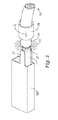
- FIG. 3 an assembled connector 10 according to the invention can be seen.
- Fig. 3 shows the outer conductive housing 1, the coaxial cable 19 which is connected to the outer conductive housing 1 and which comprises an outer jacket 24, an shield conductor 23, an dielectric isolation 22 and an inner conductor 21.
- the coaxial cable 19 is connected with an outer tube 29 to the connector 10. The connection will be described in more detail with reference to Fig. 4 . Between the outer tube 29 and the cable 19 can be seen the shield conductor 23 of the coaxial cable 19.
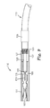
- Fig. 4 shows a cross section through the assembled connector 10 along the line X-X in Fig. 3 .
- Fig. 4 shows the connector 10 comprising the outer housing 1 with two elongated ears 27 - functioning as contact zone - and inner non conductive housing 5 with the cover plate 25. Also, the signal contact 9 is visible. It is connected to the centre conductor 21 of the coaxial cable 19.
- the coaxial cable 19 with its centre conductor 21, dielectric isolation 22, shield conductor 23 and outer jacket 24 is prepared for the connection to the connector 10. The preparation consists of cutting back the cable jacket 24 to expose the shield conductor 23.
- the shield conductor 23 and the dielectric isolation 22 are also cut back to the appropriate length.
- the inner tube 28 is arranged inside the outer conductive housing 1, the inner tube 28 is arranged.
- the centre conductor 21 and the dielectric isolation 22 of the coaxial cable 19 are arranged in the inner tube 28.
- the shield conductor 23 is arranged between the elongated ears 27 and the outer tube 29. It is also possible that the shield conductor is arranged between the contact zone (ears 27) and the inner tube 28. In that case a contact would be established when the outer tube 29 is being crimped around the ears 27 thereby pressing the ears 27 against the inner tube 28 and clamping the shield conductor 23 between the ears 27 and the inner tube 28.
- the outer tube 29 is crimped around the shield conductor 23 of the coaxial cable 19 and the contact zone in the form of elongated ears 27. Thereby, an electrical connection between the shield conductor 23 of the coaxial cable 19 and the contact zone of the outer housing 1 is established as the shield conductor 23 is clamped between the outer tube 14 and the elongated ears 27. Thus, also an electrical connection is established between the shield conductor 23 and the ground contact 11 (not shown in Fig. 4 ) since the ground contact 11 comprises two ears 17 and 18 extending out of the inner housing 5 to the outer conductive housing 1.
- the inner tube 28 is arranged in the outer conductive housing 1 as described with reference to Fig. 4 extending from the upper end of the signal contact 9 to the upper end of the ears 27 thereby accommodating the centre conductor 21 and the dielectric isolation 22.
- the outer tube 29 is placed over and/or around the ears 27 after the inner conductive housing 1 with the cable 19 and the inner tube 28 have been inserted into the outer housing 1.
- the shield conductor 23 is arranged between the outer tube 29 and the ears 27.
- By crimping the outer tube 29 around the ears 27 an electrical connection between the shield conductor 23 of the coaxial cable 19 and the contact zone of the outer housing 1 is established as the shield conductor 23 is clamped between the outer tube 29 and the elongated ears 27.
- Fig. 6 a to d are perspective views of further embodiments of the outer housing 1 of the inventive connector 10.
- the outer housing 1 comprises contact zones 27 that are integral with the outer housing 1 and have a substantially oval shape.
- the outer housing 1 comprises contact zones 27 that are integral with the outer housing 1 and have a T shape.
- the contact zone 27 of the embodiment shown in Fig. 6c is U-shaped in cross section. It may be achieved by cutting away half of the upper edge of the outer housing 1.
- the contact zone 27 of the embodiment shown in Fig. 6d has mirror-image U-shaped portions in cross section as well. It may be achieved by cutting away two rectangular pieces from the central portion of opposing sides of the outer housing 1 at opposing sides next to its upper edge.
- the outer tube would be placed and crimped around the contact zone 27.
- the other part 31 would not be effected by this.
- FIG. 7 an exploded view of another embodiment of the connector 110 according to the invention is shown.
- An inner non conductive housing 105 comprises a cover plate 125.
- the cover plate 125 is also out of non conductive material.
- a signal contact 109 can be seen within the non conductive housing 105 .
- the geometric shape of the signal contact 109 may be the same as described with reference to Fig. 1 .
- the elongated tubular outer conductive housing 101 is open at both sides.
- the outer housing 101 comprises two elongated ears 127 that function as contact zones.
- the two ears 127 are arranged in the middle of the outer housing 101, where the signal contact 9 is located.
- FIG. 8 an assembled connector 110 according to the invention can be seen.
- Fig. 3 shows the outer conductive housing 101, a coaxial cable 119 which is connected to the outer conductive housing 101 and which comprises an outer jacket 124, an shield conductor 123, an dielectric isolation 122 and an inner conductor 121.
- the coaxial cable 119 is connected with an outer tube 129 to the connector 110. The connection will be described in more detail with reference to Fig. 9 . Between the outer tube 129 and the cable 119 can be seen the shield conductor 123 of the coaxial cable 119.
- Fig. 4 shows a cross section through the connector 110 during assembly - before crimping.
- Fig. 4 shows the connector 110 comprising the outer housing 101 with two elongated ears 127 - functioning as contact zone - and inner non conductive housing 105 with the cover plate 125. Also, the signal contact 109 is visible. It is connected to the centre conductor 121 of the coaxial cable 119.
- the coaxial cable 119 with its centre conductor 121, dielectric isolation 122, shield conductor 123 and outer jacket 124 is prepared for the connection to the connector 110.
- the preparation consists of cutting back the cable jacket 124 to expose the shield conductor 123.
- the shield conductor 123 and the dielectric isolation 122 are also cut back to the appropriate length.
- an inner tube 128 is arranged inside the outer conductive housing 101. It extends from the upper end of the elongated ears 127 to the upper end of the signal contact 109 and thereby passes within the contact zone.
- the centre conductor 121 and the dielectric isolation 122 of the coaxial cable 119 are arranged in the inner tube 128 (not shown in Fig. 9 ).
- the shield conductor 122 is going to be arranged between the elongated ears 127 and the outer tube 129, which is going to be pushed over the elongated ears 127. It is also possible that the shield conductor is arranged between the contact zone (ears 127) and the inner tube 128.
- FIG. 10 an exploded view of another embodiment of the connector 210 according to the invention is shown.
- An inner non conductive housing 205 comprises a cover plate 225.
- the cover plate 225 is also out of non conductive material.
- a signal contact 209 can be seen within the non conductive housing 205 .
- the geometric shape of the signal contact 209 may be the same as described with reference to Fig. 1 .
- an outer conductive housing 201 It can also be seen an outer conductive housing 201.
- the elongated tubular outer conductive housing 201 is open at both sides.
- the outer housing 201 comprises two elongated ears 227 that function as contact zones.
- the two ears 227 are arranged in the middle of the outer housing 201, where the signal contact 209 is located.
- the outer conductive housing 205 comprises a resilient ear or wiper 232 for making electrical contact to a not shown grounding element.
Landscapes
- Coupling Device And Connection With Printed Circuit (AREA)
Abstract
The invention provides a connector (10) for a coaxial cable (19), in particular a coaxial cable having a small diameter and comprising a centre conductor (21), a dielectric isolation (22), a shield conductor (23) and an outer jacket (24), with the following features:
- an outer conductive housing (1), that is elongated and/or tubular,
- an inner non conductive housing (5) with at least one opening (3,4) for at least one contacts (9,11),
- wherein the outer conductive housing comprises at least one contact zone for electrically connecting a conductor of the coaxial cable
- and a fixing means extending at least partially in the area of the contact zone of the outer housing for electrically connecting a conductor of the coaxial cable to the contact zone.
- an outer conductive housing (1), that is elongated and/or tubular,
- an inner non conductive housing (5) with at least one opening (3,4) for at least one contacts (9,11),
- wherein the outer conductive housing comprises at least one contact zone for electrically connecting a conductor of the coaxial cable
- and a fixing means extending at least partially in the area of the contact zone of the outer housing for electrically connecting a conductor of the coaxial cable to the contact zone.
Description
- The invention relates to a termination for a coaxial cable, in particular coaxial cables having a small diameter. The invention also relates to a method of assembling a connector for a coaxial cable.
- Usually, connectors for coaxial cables are symmetrical with respect to their axis of rotation. In view of the shield effect they can be designed such that the resistance behaviour in the area of the connector is not remarkably different from the cable. Examples for such connectors are disclosed for example in
US 3,828,305 A ,EP 99 633 A WO 93/10 578 A -
US 3,828,305 A discloses a connector for a coaxial cable with an outer conductive housing, an outer ferrule and inner non conductive parts. When being attached to a coaxial cable the outer housing extends between a dielectric isolation of the cable and an outer conductor of the cable, the outer ferrule is crimped around the outer housing thereby pressing and fixing the outer conductor of the cable to the outer housing. -
EP 0 099 633 A -
WO 93/10 578 A - There are further connectors known which allow miniaturization such as for example connectors disclosed in
US 5,184,965 A . The known connector comprises an inner non conductive housing that is located in an outer conductive housing. The inner housing has two openings for contacts, a signal and a ground contact. When a coaxial cable is attached to the connector the inner conductor of the coaxial cable is connected to the signal contact within the inner housing and the outer conductor of the coaxial cable is connected by welding to the outer housing. The outer housing is electrically connected with the ground contact. - There is a need for connectors for coaxial cables which allow miniaturization that is easy to manufacture with a high standard of quality and which is cost effective. There is also a need for connectors for coaxial cables that consist of only a few parts and therefore are cost effective. It would be desirable to provide easy to manufacture connectors with which it is possible to get a reliable connection between the cable and the connector. There is a need for coaxial cable connectors which can be packed together in a rectangular array to allow multi coaxial termination at lowest space demand. And there is a need for coaxial cable connectors which are suitable to be terminated in the field.
- There is also a need for a method of assembling a connector for coaxial cables which does not need high control efforts and still offers a high quality standard.
- With such a process it would be possible to establish a reliable, affordable manufacturing process.
- The present invention provides a connector for a coaxial cable, in particular a coaxial cable having a small diameter and comprising a centre conductor, a dielectric isolation, a shield conductor and an outer jacket. The inventive connector further comprises an outer elongated and/or tubular housing, that is conductive and comprises at least one contact zone for electrically connecting a conductor of the coaxial cable, an inner non conductive housing with at least one opening for at least one contact and a fixing means extending at least partially in the area of the contact zone of the outer housing for electrically connecting the conductor of the coaxial cable to the contact zone.
- The coaxial cable according to the invention is an electrical cable comprising a centre conductor or a round conducting wire surrounded by a dielectric isolation or insulating spacer, a tubular shield conductor around the dielectric isolation and an outer isolating layer or jacket. The invention relates in particular to connectors for coaxial cables having a small diameter. Such cables are used for example in the field of telecommunication as a high-frequency transmission line to carry high-frequency or broadband signals. Because the electromagnetic field carrying the signal exists ideally only in the space between the inner and the outer conductor, it cannot interfere with or suffer interference from external electromagnetic fields.
- In the connector according to the invention, an inner housing is located within the conductive elongated tubular outer metal housing covering the inner housing. The inner housing may consist of two parts adapted to be plugged into the outer housing. After assembly, the inner housing may have a cross-sectional outer profile which corresponds substantially to the inner dimensions of the outer housing, preferably to the inner cross section of the inner space thereof. The inner housing may have spaces or the like which receive at least one contact in a fixed position. Such a connector is also known as an electromagnetic interface shield box (EMI shield box). The elongated tubular outer housing e.g. in a rectangular shape allows a close positioning of one connector next to another and offers in combination with a carrier a single connector with multi coaxial connections at standard contact spacing.
- According to the invention the outer housing comprises at least one contact zone for electrically connecting a conductor of the coaxial cable thereto. A contact zone can be any zone on or part of the outer conductive housing that extends beyond the non-conductive housing located inside the outer conductive housing which is adapted to make electrical contact with a conductor of the coaxial cable. The contact zone can have a certain geometrical shape to achieve a reliable contact. It is also possible that the contact zone has certain material properties that help to achieve a reliable contact between the conductive outer housing and a conductor of the coaxial cable.
- The connector according to the invention also provides a fixing means extending at least partially in the area of the contact zone of the outer housing for electrically connecting a conductor of the coaxial cable to the outer housing. The fixing means may be any kind of means that is adapted to fix and electrically contact a cable to the outer housing, e.g. a mechanical fixing means.
- According to one embodiment of the invention the inner housing comprises at least one signal contact and one ground contact. The inner housing has spaces or the like which receive the signal and the ground contact in fixed relative positions. The contacts may be out of bend metal sheet and may comprise a specific geometric shape. The contacts have the function to electrically connect the connector with further electronic components such as pins of a socket. The signal contact may make interconnection of the signal path with the centre conductor and the ground contact with the shield conductor. The centre conductor may be directly mechanically fixed to the signal contact by means of crimping, IDC, welding and/or soldering. The shield conductor may make the interconnection with the ground contact over the outer housing by an integrated dedicated wiper. It is also possible that the inner housing comprises only one contact, e.g. a signal contact. In that case the signal contact may make interconnection with the centre conductor. The shield conductor may be connected to the outer housing. The interconnection to ground may be achieved by a separate grounding element connecting multiple outer conductive housings. It is also possible to design a outer conductive housing with a flexible ear or wiper to establish an electrical contact to a separate grounding element.
- According to another embodiment of the invention the fixing means is an outer tube. A tube is easy to manufacture and therefore a cheap component. The outer tube can be made of any material that can easily be deformed such as for example plastic, metal etc. Preferably it is made out of metal. The fixing means may also be a prestressed spring sleeve which is able to apply a force to the contact zone. It is also possible to use a wire and wrap it around the contact zone by wire wrapping.
- According to a further embodiment of the invention the outer tube is crimped to the outer conductive housing thereby covering at least part of the contact zone of the outer conductive housing. By crimping the outer tube around at least parts of the conductive housing, the outer tube will be deformed. Depending on the force that is applied to the outer tube the conductive housing may be deformed as well. Thereby the shapes of the outer tube and the outer housing will be aligned. If a conductor of the cable would be placed between the outer housing and the outer tube the alignment of the shapes of the outer housing and the outer tube would fix the conductor between the tube and the housing. Since this takes place in the area of the contact zone, electrical contact between the conductor of the cable and the outer housing is provided. Preferably the shield conductor is electrically connected to the outer housing. The invention provides a mechanical solution for a direct crimped termination of the braid or shield contact of a coaxial cable to the EMI shield box. That has the advantage that no thermal stress is put on the cable and on the connector and that the termination is independent from a temperature range of the cable. Therefore, low cost cables can be used as well. The connector according to the invention can be terminated in the field by the application of standard tools e.g. crimping tools. Instead of a tube being crimped to the outer conductive housing two half shells, that are being joint together by pushing them into each other could be used as well. When the two half shells are made out of plastic the connection between the two shells can be established by welding due to friction energy during pushing the two parts together.
- The outer tube may be conductive. This has the advantage that besides a direct contact between a conductor and the outer housing a second electrical path between the coaxial cable and the outer housing over the tube can be established. The outer tube may be manufactured out of the following materials: metal, metallised plastic or a compound of metal and plastic and/or metallised plastic.
- According to a further example of the invention an inner tube is arranged in the outer conductive housing. The inner tube may be arranged at least partially in the area of the contact zone of the outer conductive housing. That has the advantage that the inner tube provides a counter bearing for the outer tube being crimped around the contact zone thereby preventing any deformation inside the inner tube. As mentioned above a tube is easy to manufacture and is therefore a cheap component. The inner tube can be made of metal, plastic, metallised plastic or a compound of metal and plastic and or metallised plastic etc..
- The inner tube may extend inside of the conductive housing. By that a stable construction is achieved. It is also possible that the inner tube only extends in the area of the contact zone.
- The inner tube may be adapted to carry the coaxial cable. Therefore the dimensions of the coaxial cable and the inner tube have to be adapted to each other. The inner tube further may be designed to accommodate the centre conductor and the dielectric isolation of the coaxial cable. In this case the dielectric isolation of the coaxial cable and the inner tube have to be adapted in their dimensions. The outer diameter of the dielectric isolation has to be as big as or smaller then the inner diameter of the inner tube.
- The inner tube may be conductive. This has the advantage that the inventive connector has nearly the same geometrically conditions as the cable it selves. By that it is possible that the electromagnetic field carrying the signal exists only in the space between the inner conductor and the inner tube (instead of the outer conductor of the cable). Therefore the connector has approximately the same electrical properties as the coaxial cable, e.g. the same resistance behaviour.
- According to yet another embodiment of the invention the outer conductive housing is rectangular in cross section. The rectangular shape of the outer conductive housing has the advantage that it is possible to assemble one outer housing next to another in a very space saving manner. That helps to design space saving plugs with a plurality of connectors according to the invention arranged in it.
- The contact zone may be an elongated portion of the outer conductive housing. It is a production advantage when the contact zone is part of the outer housing since only one part has to be manufactured. It is also possible to manufacture at least two parts and to connect them. To design the contact zone as an elongated portion of the outer conductive housing is a good solution when the outer tube is being crimped around the contact zone, since the deformation takes place apart from the rest of the connector and other parts will not be effected.
- The elongated portion that functions as contact zone may further be one or more tabs extending from the conductive housing and having a rectangular shape. A rectangular shape is a simple shape that makes the process of manufacturing easy. Other shapes are possible as well, such as for example a round shaped contact zone, a triangular shaped contact zone, a T-shaped contact zone, a polygonal shaped contact zone etc..
- The elongated portion that functions as contact zone may be resilient. This helps to achieve a reliable electrical contact when the outer tube is crimped around the contact zones since the shape of the outer tube and the shape of the contact zone are being aligned during the crimping process. The contact zone may be out of the same material as the outer housing. It may also be out of another material such as for example another special metal composition that has very good properties with respect to making electrical contact to a conductor such as for example a shield conductor of a coaxial cable.
- It is possible to have two or more contact zones at the outer housing. The contact zones may be achieved by cutting out portions out of the outer housing. The cut out portions may have for example a rectangular shape, a triangular shape or a polygonal shape. If the outer housing comprises an elongated, tubular, rectangular body the cut out portion could also cover half of the upper edge of the body.
- Those contact zones may be located on two opposing sides of the outer conductive housing. They may also be located on the same side of the housing or on two, or three adjacent sides of the outer conductive housing.
- The present invention also provides a method of assembling a connector for a coaxial cable, in particular a coaxial cable having a small diameter and comprising a centre conductor, a dielectric isolation, a shield conductor and an outer jacket, comprising the following steps:
- connecting the centre conductor of the coaxial cable to a signal contact,
- inserting the inner non conducive housing into the outer conductive housing,
- bringing the shield conductor of the coaxial cable in the area of a contact zone of the outer housing of the connector,
- bringing a fixing means in the area of the contact zone and
- crimping the fixing means together with the shield conductor to the contact zone.
- This method has the advantage that no thermal stress is put on the cable and the connector therefore the waste in the production can be minimized. Another advantage is that crimping is a very reliable process with the result that the quality of the process is very high and the effort which has to be taken for controlling the process is very low. That makes the method of assembling a connector according to the invention to a reliable and cost effective process. A further advantage is that the connector according to the invention can be assembled in the field by using standard tools.
- The invention will now be described in more detail with reference to the following Figures exemplifying particular embodiments of the invention:
- Fig. 1
- is an exploded view of an EMI shield box;
- Fig. 2
- is an exploded view of the connector according to one embodiment of the invention with a contact zone and a fixing means;
- Fig. 3
- is a perspective view of the assembled connector according to the invention shown in
Fig. 2 with contact zone and fixing means; - Fig. 4
- is a cross sectional view of the assembled connector according to the invention shown in
Fig. 2 along the line X-X inFig. 3 ; - Fig. 5
- is a perspective view of the connector according to the invention shown in
Fig. 2 during assembling; - Fig. 6 a- d
- are perspective views of other embodiments of the outer housing of a connector according to the invention;
- Fig. 7
- is an exploded view of the connector according to another embodiment of the invention;
- Fig. 8
- is a perspective view of the assembled connector according to the invention shown in
Fig. 7 ; - Fig. 9
- is a cross sectional view of the connector according to the invention shown in
Fig. 7 during assembly and - Fig. 10
- is an exploded view of the connector according to another embodiment of the invention.
- Herein below various embodiments of the present invention are described and shown in the drawings wherein like elements are provided with the same reference numbers.
-
Fig. 1 shows an electromagneticinterface shield box 10. InFig. 1 an elongated tubularouter housing 1 of electrically conductive material can be seen which is open on oneside 2 and comprises two openings 3, 4 on the opposing side. The outer conductive housing is rectangular in cross section. InFig. 1 an inner nonconductive housing 5 can be seen as well that is also elongated and tubular. The inner nonconductive housing 5 hasrecesses - It can also be seen a signal contact 9 and a
ground contact 11 of theconnector 10. The signal contact 9 and theground contact 11 are made out of bend sheet metal in a suitable manner. The signal contact 9 includes a front passage-shaped plug-inportion 12 which is U-shaped in cross section and arear connection portion 13, also U-shaped in cross section and reversed from the plug-inportion 12. Theground contact 11 includes a front plug-inportion 14 which is similar structured asportion 12. Aresilient ear 17 is bent outwardly at the plug-inportion 14. Theresilient ear 17 interconnects theground contact 11 with the outerconductive housing 1 in the assembled state of the shield box. 10. - In
Fig. 1 it is also shown acoaxial cable 19 with acentre conductor 21, adielectric isolation 22, ashield conductor 23 and anouter jacket 24. Thecoaxial cable 19 is prepared at one end for the connection with the signal contact 9 and theground contact 11. The preparation of the cable end is such that theshield conductor 23 is terminated at a distance from the signal contact 9 with a portion of thedielectric isolation 22 there between. As shown inFig. 1 thecentre conductor 21 rests on the U-shaped part of theconnection portion 13 of the signal contact 9 and is attached thereto e.g. by welding, soldering, crimping etc. - By lowering the inner non
conductive housing 5 into the direction of the arrow A the signal contact 9, theground contact 11 and a portion of thecable 19 are placed inside the inner housing and are held in place. The signal contact 9 comes into therecess 6, theground contact 11 comes into therecess 7 and the two ears of theground contact 11 extend through therecess 7 and 8. The outerconductive housing 1 can be pushed onto this arrangement as indicated by arrow B and the signal contact 9 and theground contact 11 get next to the openings 3 and 4 of the outerconductive housing 1 so that they are accessible from outside. The inventive concept of how to connect thecoaxial cable 19 to theconnector 10 will be described with reference to the following figures. - In
Fig. 2 an exploded view of theconnector 10 according to the invention is shown. The inner nonconductive housing 5 comprises acover plate 25. Thecover plate 25 is also out of non conductive material. Within the nonconductive housing 5 the signal contact 9 and theground contact 11 can be seen. Theground contact 11 comprisesprotrusions 15 for fixing theground contact 11 inside theinner housing 5. It can also be seen theresilient ear 17 of theground contact 11 for making an interconnection between the outerconductive housing 1 and theground contact 11. It can also be seen the outerconductive housing 1. The elongated tubular outerconductive housing 1 is open at both sides. At theside 2 which opposes the side directed to the inner nonconductive housing 5, theouter housing 1 comprises twoelongated ears 27 that function as contact zones and will be described in more detail below. The twoears 27 are arranged at the side of theconductive housing 1 where the signal contact 9 is located. InFig. 2 acoaxial cable 19 is shown as well. Thecoaxial cable 19 consists of acentre conductor 21, adielectric isolation 22, ashield conductor 23 and anouter jacket 24. Thecoaxial cable 19 is prepared for the connection with theconnector 10. Theouter jacket 24 is therefore stripped back as well as theshield conductor 23 and thedielectric isolation 22 so that every layer of the coaxial cable can be seen. InFig. 2 also aninner tube 28 and anouter tube 29 can be seen. They are part of one embodiment of theinventive connector 10 and will be described in connection with the further figures. - In
Fig. 3 an assembledconnector 10 according to the invention can be seen.Fig. 3 shows the outerconductive housing 1, thecoaxial cable 19 which is connected to the outerconductive housing 1 and which comprises anouter jacket 24, anshield conductor 23, andielectric isolation 22 and aninner conductor 21. Thecoaxial cable 19 is connected with anouter tube 29 to theconnector 10. The connection will be described in more detail with reference toFig. 4 . Between theouter tube 29 and thecable 19 can be seen theshield conductor 23 of thecoaxial cable 19. -
Fig. 4 shows a cross section through the assembledconnector 10 along the line X-X inFig. 3 .Fig. 4 shows theconnector 10 comprising theouter housing 1 with two elongated ears 27 - functioning as contact zone - and inner nonconductive housing 5 with thecover plate 25. Also, the signal contact 9 is visible. It is connected to thecentre conductor 21 of thecoaxial cable 19. Thecoaxial cable 19 with itscentre conductor 21,dielectric isolation 22,shield conductor 23 andouter jacket 24 is prepared for the connection to theconnector 10. The preparation consists of cutting back thecable jacket 24 to expose theshield conductor 23. Theshield conductor 23 and thedielectric isolation 22 are also cut back to the appropriate length. Inside the outerconductive housing 1, theinner tube 28 is arranged. It extends from the upper end of theelongated ears 27 to the upper end of the signal contact 9 and thereby passes within the contact zone. Thecentre conductor 21 and thedielectric isolation 22 of thecoaxial cable 19 are arranged in theinner tube 28. Theshield conductor 23 is arranged between theelongated ears 27 and theouter tube 29. It is also possible that the shield conductor is arranged between the contact zone (ears 27) and theinner tube 28. In that case a contact would be established when theouter tube 29 is being crimped around theears 27 thereby pressing theears 27 against theinner tube 28 and clamping theshield conductor 23 between theears 27 and theinner tube 28. Theouter tube 29 is crimped around theshield conductor 23 of thecoaxial cable 19 and the contact zone in the form ofelongated ears 27. Thereby, an electrical connection between theshield conductor 23 of thecoaxial cable 19 and the contact zone of theouter housing 1 is established as theshield conductor 23 is clamped between theouter tube 14 and theelongated ears 27. Thus, also an electrical connection is established between theshield conductor 23 and the ground contact 11 (not shown inFig. 4 ) since theground contact 11 comprises twoears 17 and 18 extending out of theinner housing 5 to the outerconductive housing 1. Furthermore, a mechanical connection between theshield conductor 23 and theelongated ears 27 of theouter housing 1 of theconnector 10 is achieved as well and thus, a mechanical connection between theconnector 10 and thecoaxial cable 19 is achieved. Thereby, strain relieve of thecoaxial cable 19 relative to theouter housing 1 of theconnector 10 is provided as well. - In connection with
Fig. 5 the assembling of the inventive connector is described. As described above with reference toFig. 1 first thecentre conductor 21 is fixed at the signal contact 9 of theconnector 1. Then the signal contact 9, theground contact 11 and the end portion of thecoaxial cable 19 are arranged in the inner nonconductive housing 5 which then is closed with thecover plate 25.Inner housing 5,cover plate 25 together with the end portion of thecoaxial cable 19 are inserted into the outerconductive housing 1. Thereby shieldconductor 23 of thecoaxial cable 19 is arranged in the area of theelongated ears 27 of the outerconductive housing 1. The coaxial cable is prepared in a way that theouter jacket 24 terminates near the upper end of theelongated ears 27. - The
inner tube 28 is arranged in the outerconductive housing 1 as described with reference toFig. 4 extending from the upper end of the signal contact 9 to the upper end of theears 27 thereby accommodating thecentre conductor 21 and thedielectric isolation 22. Theouter tube 29 is placed over and/or around theears 27 after the innerconductive housing 1 with thecable 19 and theinner tube 28 have been inserted into theouter housing 1. By placing theouter tube 29 over theears 27 theshield conductor 23 is arranged between theouter tube 29 and theears 27. By crimping theouter tube 29 around theears 27 an electrical connection between theshield conductor 23 of thecoaxial cable 19 and the contact zone of theouter housing 1 is established as theshield conductor 23 is clamped between theouter tube 29 and theelongated ears 27. Thus, also an electrical connection is established between theshield conductor 23 and the ground contact 11 (not shown inFig. 4 ) since theground contact 11 comprises aresilient ear 17 extending out of theinner housing 5 to the outerconductive housing 1. Furthermore, a mechanical connection between theshield conductor 23 and theelongated ears 27 of theouter housing 1 of theconnector 10 is achieved as well and thus, a mechanical connection between theconnector 10 and thecoaxial cable 19 is achieved. Thereby, strain relieve of thecoaxial cable 19 relative to theouter housing 1 of theconnector 10 is provided as well. -
Fig. 6 a to d are perspective views of further embodiments of theouter housing 1 of theinventive connector 10. InFig. 6 a theouter housing 1 comprisescontact zones 27 that are integral with theouter housing 1 and have a substantially oval shape. InFig. 6b theouter housing 1 comprisescontact zones 27 that are integral with theouter housing 1 and have a T shape. Thecontact zone 27 of the embodiment shown inFig. 6c is U-shaped in cross section. It may be achieved by cutting away half of the upper edge of theouter housing 1. Thecontact zone 27 of the embodiment shown inFig. 6d has mirror-image U-shaped portions in cross section as well. It may be achieved by cutting away two rectangular pieces from the central portion of opposing sides of theouter housing 1 at opposing sides next to its upper edge. During assembly of theconnector 10 according to the invention the outer tube would be placed and crimped around thecontact zone 27. Theother part 31 would not be effected by this. - In
Fig. 7 an exploded view of another embodiment of theconnector 110 according to the invention is shown. An inner nonconductive housing 105 comprises acover plate 125. Thecover plate 125 is also out of non conductive material. Within the non conductive housing 105 asignal contact 109 can be seen. The geometric shape of thesignal contact 109 may be the same as described with reference toFig. 1 . It can also be seen an outerconductive housing 101. The elongated tubular outerconductive housing 101 is open at both sides. At theside 102 which opposes the side directed to the inner nonconductive housing 105, theouter housing 101 comprises twoelongated ears 127 that function as contact zones. - The two
ears 127 are arranged in the middle of theouter housing 101, where the signal contact 9 is located. - In
Fig. 8 an assembledconnector 110 according to the invention can be seen.Fig. 3 shows the outerconductive housing 101, acoaxial cable 119 which is connected to the outerconductive housing 101 and which comprises anouter jacket 124, anshield conductor 123, andielectric isolation 122 and aninner conductor 121. Thecoaxial cable 119 is connected with anouter tube 129 to theconnector 110. The connection will be described in more detail with reference toFig. 9 . Between theouter tube 129 and thecable 119 can be seen theshield conductor 123 of thecoaxial cable 119. -
Fig. 4 shows a cross section through theconnector 110 during assembly - before crimping.Fig. 4 shows theconnector 110 comprising theouter housing 101 with two elongated ears 127 - functioning as contact zone - and inner nonconductive housing 105 with thecover plate 125. Also, thesignal contact 109 is visible. It is connected to thecentre conductor 121 of thecoaxial cable 119. Thecoaxial cable 119 with itscentre conductor 121,dielectric isolation 122,shield conductor 123 andouter jacket 124 is prepared for the connection to theconnector 110. The preparation consists of cutting back thecable jacket 124 to expose theshield conductor 123. Theshield conductor 123 and thedielectric isolation 122 are also cut back to the appropriate length. Inside the outerconductive housing 101, aninner tube 128 is arranged. It extends from the upper end of theelongated ears 127 to the upper end of thesignal contact 109 and thereby passes within the contact zone. Thecentre conductor 121 and thedielectric isolation 122 of thecoaxial cable 119 are arranged in the inner tube 128 (not shown inFig. 9 ). During assembly theshield conductor 122 is going to be arranged between theelongated ears 127 and theouter tube 129, which is going to be pushed over theelongated ears 127. It is also possible that the shield conductor is arranged between the contact zone (ears 127) and theinner tube 128. In that case a contact would be established when theouter tube 129 is being crimped around theears 127 thereby pressing theears 127 against theinner tube 128 and clamping theshield conductor 123 between theears 127 and theinner tube 128. Theouter tube 129 is crimped around theshield conductor 123 of thecoaxial cable 119 and the contact zone in the form ofelongated ears 127. Thereby, an electrical connection between theshield conductor 123 of thecoaxial cable 119 and the contact zone of theouter housing 101 is established as theshield conductor 123 is clamped between the outer tube 114 and theelongated ears 127. For grounding the connector 101 a separate grounding element (not shown) could be established connecting multiple connectors being arranged next to each other. Furthermore, a mechanical connection between theshield conductor 123 and theelongated ears 127 of theouter housing 101 of theconnector 110 is achieved as well and thus, a mechanical connection between theconnector 110 and thecoaxial cable 119 is achieved. Thereby, strain relieve of thecoaxial cable 119 relative to theouter housing 101 of theconnector 110 is provided as well. - In
Fig. 10 an exploded view of another embodiment of theconnector 210 according to the invention is shown. An inner nonconductive housing 205 comprises acover plate 225. Thecover plate 225 is also out of non conductive material. Within the non conductive housing 205 asignal contact 209 can be seen. The geometric shape of thesignal contact 209 may be the same as described with reference toFig. 1 . It can also be seen an outerconductive housing 201. The elongated tubular outerconductive housing 201 is open at both sides. At theside 202 which opposes the side directed to the inner nonconductive housing 205, theouter housing 201 comprises twoelongated ears 227 that function as contact zones. The twoears 227 are arranged in the middle of theouter housing 201, where thesignal contact 209 is located. The outerconductive housing 205 comprises a resilient ear orwiper 232 for making electrical contact to a not shown grounding element. -
- 1
- outer conductive housing
- 2
- side
- 3
- opening
- 4
- opening
- 5
- inner non conductive housing
- 6
- recess
- 7
- recess
- 8
- recess
- 9
- signal contact
- 10
- connector, EMI shield box
- 11
- ground contact
- 12
- plug-in portion of signal contact
- 13
- rear connection portion of signal contact
- 14
- plug-in portion of ground contact
- 15
- protrusions of ground contact
- 17
- ear at plug-in portion of ground contact
- 19
- coaxial cable
- 21
- centre conductor
- 22
- dielectric isolation
- 23
- shield conductor
- 24
- outer jacket
- 25
- cover plate
- 27
- elongated ear, contact zone
- 28
- inner tube
- 29
- outer tube
- 31
- other part
- 101
- outer conductive housing
- 102
- side
- 105
- inner non conductive housing
- 109
- signal contact
- 110
- connector
- 119
- coaxial cable
- 121
- centre conductor
- 122
- dielectric isolation
- 123
- shield conductor
- 124
- outer jacket
- 127
- elongated ear, contact zone
- 129
- outer tube
- 201
- outer conductive housing
- 202
- side
- 205
- inner non conductive housing
- 209
- signal contact
- 210
- connector
- 225
- cover plate
- 227
- elongated ear, contact zone
- 232
- resilient ear, wiper
- A
- direction of mounting movement of
inner housing 5 - B
- direction of mounting movement outer
conductive housing 1 - C
- direction of mounting movement
outer tube 29
Claims (19)
- A connector (10) for a coaxial cable (19), in particular a coaxial cable having a small diameter and comprising a centre conductor (21), a dielectric isolation (22), a shield conductor (23) and an outer jacket (24), said connector comprising:- an outer conductive housing (1), that is elongated and/or tubular,- an inner non conductive housing (5) with at least one opening (3, 4) for at least one contact (9, 11),- wherein the outer conductive housing comprises at least one contact zone for electrically connecting a conductor of the coaxial cable- and a fixing means extending at least partially in the area of the contact zone of the outer housing for electrically connecting a conductor of the coaxial cable to the contact zone.
- The connector according to claim 1, wherein the inner housing (5) comprises at least one signal contact (9) and one ground contact (11).
- The connector according to claim 1 or 2, wherein the fixing means is an outer tube (29).
- The connector according to any of the preceding claims, wherein the outer tube (29) is crimped to the outer conductive housing (1) thereby covering at least part of the contact zone of the outer conductive housing.
- The connector according to any of the preceding claims, wherein the outer tube (29) is conductive.
- The connector according to any of the preceding claims, wherein an inner tube (28) is arranged in the outer conductive housing (1).
- The connector according to any of the preceding claims, wherein the inner tube (28) is arranged at least partially in the area of the contact zone of the outer conductive housing (1).
- The connector according to any of the preceding claims, wherein the inner tube (28) extends inside of the conductive housing (1).
- The connector according to any of the preceding claims, wherein the inner tube (28) is adapted to carry the coaxial cable (19).
- The connector according to any of the preceding claims, wherein the inner tube (28) is designed to accommodate the dielectric isolation (22) of the coaxial cable (19).
- The connector according to any of the preceding claims, wherein the inner tube (28) is conductive.
- The connector according to any of the preceding claims, wherein the outer conductive housing (1) is rectangular in cross section.
- The connector according to any of the preceding claims, wherein the contact zone is at least one elongated portion (27) of the outer conductive housing (1).
- The connector according to claim 14, wherein the elongated portion (27) is rectangular.
- The connector according to claim 14 or 15, wherein the elongated portion (27) is resilient.
- The connector according to any of the preceding claims, wherein the outer housing (1) comprises at least two contact zones.
- The connector according to claim 16, wherein the contact zones are located on two opposing sides of the outer conductive housing (1).
- Method of assembling a connector for a coaxial cable, in particular a coaxial cable having a small diameter and comprising a centre conductor, a dielectric isolation, a shield conductor and an outer jacket, comprising the features of the preceding claims, said method comprising the steps of- connecting the centre conductor of the coaxial cable to a contact,- inserting the inner non conductive housing into the outer conductive housing,- bringing the shield conductor of the coaxial cable in the area of the contact zone,- bringing the fixing means in the area of the contact zone and- crimping the fixing means together with the shield conductor to the contact zone.
- Method according to claim 18 wherein an inner tube - accommodating the centre conductor and the dielectric isolation - is inserted as well into the outer conductive housing.
Priority Applications (1)
| Application Number | Priority Date | Filing Date | Title |
|---|---|---|---|
| EP07113182A EP2019450A1 (en) | 2007-07-26 | 2007-07-26 | Connector for coaxial cable |
Applications Claiming Priority (1)
| Application Number | Priority Date | Filing Date | Title |
|---|---|---|---|
| EP07113182A EP2019450A1 (en) | 2007-07-26 | 2007-07-26 | Connector for coaxial cable |
Publications (1)
| Publication Number | Publication Date |
|---|---|
| EP2019450A1 true EP2019450A1 (en) | 2009-01-28 |
Family
ID=38844990
Family Applications (1)
| Application Number | Title | Priority Date | Filing Date |
|---|---|---|---|
| EP07113182A Withdrawn EP2019450A1 (en) | 2007-07-26 | 2007-07-26 | Connector for coaxial cable |
Country Status (1)
| Country | Link |
|---|---|
| EP (1) | EP2019450A1 (en) |
Cited By (2)
| Publication number | Priority date | Publication date | Assignee | Title |
|---|---|---|---|---|
| WO2014202758A1 (en) * | 2013-06-20 | 2014-12-24 | Phoenix Contact Gmbh & Co. Kg | Electrical plug connector |
| JP2022153116A (en) * | 2021-03-29 | 2022-10-12 | ミツミ電機株式会社 | Electric connector |
Citations (4)
| Publication number | Priority date | Publication date | Assignee | Title |
|---|---|---|---|---|
| US5184965A (en) * | 1991-05-17 | 1993-02-09 | Minnesota Mining And Manufacturing Company | Connector for coaxial cables |
| US5197904A (en) * | 1992-09-04 | 1993-03-30 | Michael Gold | Connector for coaxially shielded cables |
| EP0902502A1 (en) * | 1997-09-12 | 1999-03-17 | Itt Manufacturing Enterprises, Inc. | Screened cable terminating ferrule |
| EP1003244A1 (en) * | 1998-11-19 | 2000-05-24 | Sumitomo Wiring Systems, Ltd. | A shielded connector and a method for connecting a shielded connector with a shielded cable |
-
2007
- 2007-07-26 EP EP07113182A patent/EP2019450A1/en not_active Withdrawn
Patent Citations (4)
| Publication number | Priority date | Publication date | Assignee | Title |
|---|---|---|---|---|
| US5184965A (en) * | 1991-05-17 | 1993-02-09 | Minnesota Mining And Manufacturing Company | Connector for coaxial cables |
| US5197904A (en) * | 1992-09-04 | 1993-03-30 | Michael Gold | Connector for coaxially shielded cables |
| EP0902502A1 (en) * | 1997-09-12 | 1999-03-17 | Itt Manufacturing Enterprises, Inc. | Screened cable terminating ferrule |
| EP1003244A1 (en) * | 1998-11-19 | 2000-05-24 | Sumitomo Wiring Systems, Ltd. | A shielded connector and a method for connecting a shielded connector with a shielded cable |
Cited By (2)
| Publication number | Priority date | Publication date | Assignee | Title |
|---|---|---|---|---|
| WO2014202758A1 (en) * | 2013-06-20 | 2014-12-24 | Phoenix Contact Gmbh & Co. Kg | Electrical plug connector |
| JP2022153116A (en) * | 2021-03-29 | 2022-10-12 | ミツミ電機株式会社 | Electric connector |
Similar Documents
| Publication | Publication Date | Title |
|---|---|---|
| TWI528661B (en) | Cable header connector | |
| JP3656187B2 (en) | Connector for shielded cable | |
| CN101800383B (en) | Modular plug assemblies | |
| EP0099633B1 (en) | Coaxial connector plug | |
| EP0118168B2 (en) | Electrical plug connector and receptacle therefor | |
| TWI528665B (en) | Cable header connector | |
| KR100256927B1 (en) | Shield connection system of high speed cable | |
| TWI548162B (en) | Cable header connector | |
| US10699823B2 (en) | Cable assembly for electrical connector | |
| EP2005536A2 (en) | Shielded jack assemblies and methods for forming a cable termination | |
| US6966797B2 (en) | High-speed cable assembly | |
| EP4539264A2 (en) | Angled subassembly for an angled connector and method of assembling thereof | |
| EP0542075B1 (en) | Method of terminating miniature coaxial electrical connector and resulting terminated connector | |
| EP4535574A2 (en) | Angled subassembly for an angled connector and method of assembling thereof | |
| US7909645B2 (en) | Coaxial cable connector housing | |
| JP3425634B2 (en) | Electrical connector with shield termination for high-speed cables | |
| EP2019450A1 (en) | Connector for coaxial cable | |
| US20240313488A1 (en) | Multi-piece coaxial plug connector with variably configurable interface geometry | |
| US12586959B2 (en) | Angled connector | |
| US11462342B2 (en) | Cable harness assembly with a shielded twisted pair cable | |
| JP2005038703A (en) | Wire connector | |
| MXPA97001559A (en) | System for the termination of the protection of a high speed cable |
Legal Events
| Date | Code | Title | Description |
|---|---|---|---|
| PUAI | Public reference made under article 153(3) epc to a published international application that has entered the european phase |
Free format text: ORIGINAL CODE: 0009012 |
|
| AK | Designated contracting states |
Kind code of ref document: A1 Designated state(s): AT BE BG CH CY CZ DE DK EE ES FI FR GB GR HU IE IS IT LI LT LU LV MC MT NL PL PT RO SE SI SK TR |
|
| AX | Request for extension of the european patent |
Extension state: AL BA HR MK RS |
|
| AKX | Designation fees paid | ||
| STAA | Information on the status of an ep patent application or granted ep patent |
Free format text: STATUS: THE APPLICATION IS DEEMED TO BE WITHDRAWN |
|
| 18D | Application deemed to be withdrawn |
Effective date: 20090729 |
|
| REG | Reference to a national code |
Ref country code: DE Ref legal event code: 8566 |