EP2018936A1 - A footplate - Google Patents
A footplate Download PDFInfo
- Publication number
- EP2018936A1 EP2018936A1 EP20070113273 EP07113273A EP2018936A1 EP 2018936 A1 EP2018936 A1 EP 2018936A1 EP 20070113273 EP20070113273 EP 20070113273 EP 07113273 A EP07113273 A EP 07113273A EP 2018936 A1 EP2018936 A1 EP 2018936A1
- Authority
- EP
- European Patent Office
- Prior art keywords
- footplate
- guide
- hand
- dual
- held tool
- Prior art date
- Legal status (The legal status is an assumption and is not a legal conclusion. Google has not performed a legal analysis and makes no representation as to the accuracy of the status listed.)
- Granted
Links
Images





Classifications
-
- B—PERFORMING OPERATIONS; TRANSPORTING
- B23—MACHINE TOOLS; METAL-WORKING NOT OTHERWISE PROVIDED FOR
- B23Q—DETAILS, COMPONENTS, OR ACCESSORIES FOR MACHINE TOOLS, e.g. ARRANGEMENTS FOR COPYING OR CONTROLLING; MACHINE TOOLS IN GENERAL CHARACTERISED BY THE CONSTRUCTION OF PARTICULAR DETAILS OR COMPONENTS; COMBINATIONS OR ASSOCIATIONS OF METAL-WORKING MACHINES, NOT DIRECTED TO A PARTICULAR RESULT
- B23Q9/00—Arrangements for supporting or guiding portable metal-working machines or apparatus
- B23Q9/0014—Portable machines provided with or cooperating with guide means supported directly by the workpiece during action
-
- Y—GENERAL TAGGING OF NEW TECHNOLOGICAL DEVELOPMENTS; GENERAL TAGGING OF CROSS-SECTIONAL TECHNOLOGIES SPANNING OVER SEVERAL SECTIONS OF THE IPC; TECHNICAL SUBJECTS COVERED BY FORMER USPC CROSS-REFERENCE ART COLLECTIONS [XRACs] AND DIGESTS
- Y10—TECHNICAL SUBJECTS COVERED BY FORMER USPC
- Y10T—TECHNICAL SUBJECTS COVERED BY FORMER US CLASSIFICATION
- Y10T83/00—Cutting
- Y10T83/667—Tool carrier or guide affixed to work during cutting
-
- Y—GENERAL TAGGING OF NEW TECHNOLOGICAL DEVELOPMENTS; GENERAL TAGGING OF CROSS-SECTIONAL TECHNOLOGIES SPANNING OVER SEVERAL SECTIONS OF THE IPC; TECHNICAL SUBJECTS COVERED BY FORMER USPC CROSS-REFERENCE ART COLLECTIONS [XRACs] AND DIGESTS
- Y10—TECHNICAL SUBJECTS COVERED BY FORMER USPC
- Y10T—TECHNICAL SUBJECTS COVERED BY FORMER US CLASSIFICATION
- Y10T83/00—Cutting
- Y10T83/667—Tool carrier or guide affixed to work during cutting
- Y10T83/68—Entirely work supported
-
- Y—GENERAL TAGGING OF NEW TECHNOLOGICAL DEVELOPMENTS; GENERAL TAGGING OF CROSS-SECTIONAL TECHNOLOGIES SPANNING OVER SEVERAL SECTIONS OF THE IPC; TECHNICAL SUBJECTS COVERED BY FORMER USPC CROSS-REFERENCE ART COLLECTIONS [XRACs] AND DIGESTS
- Y10—TECHNICAL SUBJECTS COVERED BY FORMER USPC
- Y10T—TECHNICAL SUBJECTS COVERED BY FORMER US CLASSIFICATION
- Y10T83/00—Cutting
- Y10T83/929—Tool or tool with support
- Y10T83/9454—Reciprocable type
Definitions
- the invention relates to a footplate for a hand-held tool.
- a footplate of this type is for use with a guide which is to be positioned upon a workpiece.
- the guide has a rail extending in the longitudinal direction of the guide on its upper side opposite the workpiece in the position of use.
- the footplate which is attached, or may be attached, to the tool and has on its lower side a channel for engagement of the rail of the guide, so that the tool may be positioned on the guide and guided along the rail when the rail engages the channel.
- a footplate known from DE 200 17 862 U1 has one channel for engaging the rail of one type of guide.
- the channel has two restrictions, one located at each longitudinal end of the footplate.
- the width of each restriction is defined, on the one hand, by a fixed side wall in the channel and, on the other hand, by an adjustable side wall.
- the adjustable side wall may be adjusted transversely to the longitudinal direction by an adjustment mechanism thereby altering the width of the channel.
- the adjustment mechanisms are for fine-tuning clearance between the channel and the rail so that the footplate is guided along the guide without wobbling, as it were, in an exactly linear manner.
- a footplate known from DE 36 06 525 has two channels on its lower side. Each channel can engage the rail of a different type of guide.
- the two channels are parallel to each other and are, in effect, the two parts of the of a "dual-restriction", albeit a non-adjustable dual-restriction because it cannot alter the width of either channel.
- the present invention relates to a footplate of the type mentioned at the outset, in which the footplate which has two channels. Each channel can engage the rail of a different guide.
- the object of the invention is to ensure exact linear guidance of the footplate no matter which guide is used.
- a footplate for a hand-held tool for guiding the tool along a guide comprising on its lower surface at least one dual-restriction, wherein the first part of the or each dual-restriction is for engaging a rail extending in a longitudinal direction of a first guide on the upper surface of said first guide and the second part of the or each dual-restriction is for engaging a rail extending in a longitudinal direction of a second different guide on the upper surface of said second guide, wherein the first and second parts of the or each dual-restriction each has a fixed side wall, characterised in that the first and second parts of the or each dual-restriction have an adjustable side wall arranged opposite to a respective fixed side wall.
- the adjustable side walls may be parts of separate components or different sides of one component. The adjustable side walls can fine-tune the clearance at the dual-restriction to ensure linear guidance of the footplate along the guide.
- the width between the fixed and adjustable side walls is adjustable by an adjustment mechanism.
- One sole adjustment mechanism per dual-restriction makes efficient use of the materials for making the footplate. This reduces cost and complexity.
- the adjustable side walls are both located between the fixed side walls.
- the adjustable side walls are adjacent each other and in the middle of the dual-restriction. This close proximity makes the adjustable side walls easily accessible to the adjustment mechanism.
- the adjustment mechanism comprises a rotatable eccentric element located between the adjustable side walls.
- the eccentric element can adjust the width between fixed and adjustable side walls simply by rotating about its own axis.
- the width between fixed and adjustable side walls of the first part of the dual-restriction can only increase whilst the width between fixed and adjustable side walls of the second part of the dual-restriction decreases, and vice versa. This is not important because the footplate is normally used with one guide with one type of rail at any one time.
- the adjustable side walls are opposing sides of a perimeter wall the eccentric element. This dispenses with the need for additional components between the eccentric element and the rail of the guide upon which the footplate is positioned. In other words, the perimeter wall of the eccentric element slides directly against the rail.
- the perimeter wall is a cylindrical wall arranged eccentrically in relation to the axis of rotation of the eccentric element. This ensures that the eccentric element can adjust and fine-tune the width between fixed and adjustable side walls gradually and precisely.
- the eccentric element is secured to the footplate by a fixing bolt connected to a bearing portion of the footplate, wherein the fixing bolt can be unfastened or fastened to enable or disable rotation of the eccentric, respectively.
- the fixing bolt performs the function of rotational axis and fastening means for the eccentric element. This is a simple and inexpensive means of enabling or disabling rotation of the eccentric element.
- the adjustment mechanism comprises a manually accessible actuating member for rotating the eccentric element.
- the eccentric element can be easily manipulated by the user of the tool.
- the actuating member may take the form of a knurled cylindrical knob.
- the eccentric element is can be rotated about 360°. This facilitates easy use by left-handed and right-handed users of the tool.
- the adjustment mechanism comprises two arms, each arm arranged at one end to pivot about a common pivot point so that an open mouth may be formed at the other ends of the arms, and a wedge arranged to move within the mouth according to the position of a control device, whereby movement of the wedge into the mouth forces the arms to pivot apart to reduce the width between the fixed and adjustable side walls, and whereby movement of the wedge away from the mouth allows the arms to pivot closer to each other to increase the width between the fixed and adjustable side walls.
- this design of adjustment mechanism has the advantage of being highly resistant to any external forces changing the position of the adjustable side walls.
- each arm of the alternative design of adjustment mechanism has a shoulder and one shoulder protrudes away from the other shoulder in the transverse direction, whereby one shoulder is the adjustable side wall of the first part of the dual-restriction and the other shoulder is the adjustable side wall of the second part of the dual-restriction.
- control device of the alternative design of adjustment mechanism is a grub-screw threadedly engaged with an externally accessible hole in the footplate, whereby rotation of the grub-screw into the footplate moves the wedge into the mouth and whereby rotation of the grub-screw out of the footplate allows the wedge to move out of the mouth.
- each arm is biased to pivot towards the other arm.
- a hand-held tool in the form of a plunge saw 10 is designed to slide along a guide 11.
- the plunge saw comprises a motorised circular saw blade 12 and a blade guard 14.
- the blade and blade guard are both normally substantially perpendicular to a footplate 16, but may be adjusted to be inclined to the footplate for the purpose of bevel cutting.
- the plunge saw's body 18 is pitotable in a plane perpendicular to the footplate about a hinge 20 attached to the footplate.
- the blade can be moved between an upper "parked position" 12a inside the blade guard, and a lower "plunged position" 12b protruding below the footplate.
- the blade has an axis 21 about which it rotates when turned by the motor. In use, the blade rotates in the direction of arrow W. Viewed from one end, as is best shown in Figure 1 , the axis 21 follows an arc-shaped path BP as the blade moves between parked and plunged position.
- the blade is biased into the parked position by a spring 22.
- a user can push the plunge saw downwardly, via a pair of handles 24, 26, against the spring so that the blade descends towards the plunged position 12b.
- the exact depth of the plunged position is determined by setting a depth-stop (not shown). When the user releases the handles the blade springs back to the parked position 12a.
- the user can also push the plunge saw forwardly, again via the handles, so that the footplate 14 slides along the guide 11 to ensure that the blade cuts a straight line.
- the guide is made of strong material, like, for example, metal. Sliding motion is assisted by a pair of low-friction strips 30, 32 located on the upper surface of the guide.
- the guide 11 has a straight rail 34 on its upper surface and the footplate has a substantially correspondingly-shaped middle channel 36 in its lower surface. Engagement between rail and middle channel guides the footplate as it slides along the guide.
- the plunge saw 10 is positioned on the guide 11 which is placed upon the workpiece, rather than the plunge saw being positioned directly onto the workpiece.
- a guide lip 38 made of trimmable material, like, for example, hard rubber, is located beneath a long side face 40 of the guide.
- the guide lip is oversized to be wider than the distance X between an inner surface 112 of the blade and the long side face of the guide.
- the blade's first cut severs an outer margin 38a of the guide lip. What remains of the guide lip touches the blade. In other words, there is no gap between the blade inner surface 112 and the guide lip.
- the guide lip is thereby matched to suit the blade which made the first cut.
- Each anti-slip strip 43 has the same thickness as the guide lip 38 so that the guide is evenly supported when upon a workpiece 42.
- the guide lip 38 should, preferably, be renewed and matched to the replacement blade to ensure that a clean cut is mainatined.
- Spare guide lips can be easily fixed to the underside of the guide by adhesive.
- a second guide lip 44 also made of trimmable material, like, for example, hard rubber, is located on the opposite long side face 45 of the guide.
- the second guide lip has the same thickness as the guide lip 38 and the rubber strips 43.
- the rail 34 is located in the central longitudinal plane 46 of the guide.
- the middle channel 36 is arranged so that when the plunge saw is rotated about 180° the blade overhangs the opposite long side face 45 by approximately the same distance X to perform cutting action on that opposite side.
- the second guide lip is oversized to be wider than the distance X. The blade's first cut severs an outer margin of the second guide lip and what remains is thereby matched to the blade.
- the second guide lip can be used as a back-up resource.
- the plunge saw, or guide is simply rotated through 180°.
- both guide lips can be deliberately matched to suit a particular blade so that both sides of a workpiece can be cut simply by rotating the plunge saw through 180°, rather than the rotating both the plunge saw and guide. This is an advantage when the guide is particularly long and cumbersome, like, for example, when several guides are coupled together.
- the work environment dictates that an unsupported portion of a workpiece be cut. Whilst the guide 11 is relatively strong it does, when unsupported, bow downwards under a bending moment caused by the weight of the plunge saw 10 resting thereupon. For example, when the user approaches the final stage of a cut the plunge saw rests upon an unsupported portion of the guide as it passes beyond the end of the workpiece.
- the guide tends to bow uniformly when unsupported with the plunge saw rested thereupon.
- the blade maintains its inclination with respect to the workpiece.
- the rail 34 has two outward facing sides 48, 50 which stand parallel to the longitudinal plane 46.
- the middle channel 36 includes the first parts 52a, 54a of two adjustable dual-restrictions.
- the two dual-restrictions are spaced apart in the longitudinal direction.
- the first part of dual-restriction 52a is defined, on the one hand, by an inward facing fixed side wall 56 in the middle channel 36 and, on the other hand, by an eccentric element 58.
- the eccentric element may be rotated so that the width of the first part of dual-restriction 52a, measured in a direction 62 transverse to the longitudinal plane 46, is adjusted.
- the first part of other dual-restriction 54a is also defined by a corresponding fixed side wall 56 and an identical eccentric element 60.
- the eccentric element 60 may also be rotated so that the width of the first part of other dual-restriction 54a, measured in transverse direction 62, is adjusted.
- the eccentric elements 58, 60 perform the role of the 'adjustment mechanism' mentioned in the preamble of this specification.
- the rail 34 passes through the first parts 52a, 54a of the dual-restrictions. In this way, the side wall 48 of the rail 34 slides against the fixed face 56 in the middle channel 36 and the opposite side wall 50 of the rail 34 slides against the eccentric elements 58, 60.
- the middle channel 36 has another inward facing side wall 64, opposite the fixed side wall 56, which is interrupted by the eccentric elements 58, 60. Since the footplate 11 is guided only at the first parts 52a, 54a of the dual-restrictions, the distance between the fixed side wall 56 and the interrupted side wall 64 is no longer significant, except that this distance must be greater, at least by a small amount, than the width of the rail 34.
- the widths of the first parts 52a, 54a of the dual-restrictions may be adjusted in the transverse direction 62, the clearance between guide 11 and the footplate 16 may be adjusted so that the footplate is guided without wobbling, as it were, in an exactly linear manner in the longitudinal direction. As such, it is also possible to compensate for manufacturing tolerances of the parts of the footplate.
- the widths of the first parts 52a, 54a of dual-restrictions may be slightly greater than necessary.
- the eccentric elements 58, 60 are then rotated, as described in more detail below, so that the rail 34 is located within the middle channel 36 without clearance.
- adjustable dual-restriction at only one point along the channel, which would probably have to be located in the central region of the footplate. More than two such adjustable dual-restrictions may also be provided. However, two adjustable dual-restrictions, one located at each longitudinal end of the footplate's channel, is particularly expedient.
- each eccentric element 58, 60 is coupled with a respective guide wheel 66, 67.
- Each eccentric element 58, 60 is also disposed on the footplate 16 so that it may rotate about its own axis of rotation 68, 69. Both axes of rotation are perpendicular to the plane of the footplate.
- Each eccentric element has a cylindrical circumferential surface 70, 71 which is eccentric to its respective axis of rotation 68, 69. Rotation of a guide wheel by the plunge saw's user results in rotation of a respective eccentric element.
- each eccentric element 58, 60 may be integral with a respective guide wheel.
- FIGS 10 and 11 show how the eccentric element 58 is secured to a bearing portion 74 of the footplate 16 by a fixing bolt 76 passing through the middle of the eccentric element.
- the bearing portion has a threaded hole 78 into which the threaded fixing bolt 76 is screwed.
- the hole, the fixing bolt and the axis of rotation 68 of the eccentric element are co-centric.
- the user unfastens the fixing bolt.
- the eccentric element 60 is secured to a corresponding bearing portion 74 of the footplate in exactly the same way as eccentric element 58.
- the footplate 16 also has a side channel 79 for engagement with a rail 80 of an alternative guide 82.
- the alternative guide is not symmetrical when viewed from one end because the rail is located on one side of the longitudinal central plane 46.
- the guide 82 is stiffer in on the side of the rail 80 and so it tends to bow in a skewed manner when unsupported. In these circumstances, the plunge saw and the blade will tilt to one side when the plunge saw is upon unsupported guide. The user must stop work and alter the support system of the guide to maintain an accurate cut.
- the plunge saw 10 is positioned onto the guide 82 which is placed upon the workpiece, rather than the plunge saw being placed directly onto the workpiece.
- the rail 80 has two outward facing side walls 84, 86 which stand parallel to the longitudinal plane 46.
- the side channel 79 includes the second parts 52b, 54b of the two adjustable dual-restrictions.
- Each second part of the dual-restrictions is defined, on the one hand, by a fixed side wall 88 in the side channel 79 and, on the other hand, by the same eccentric element 58, 60 as is used to adjust the first parts 52a, 54a of the dual-restrictions of the middle channel 36.
- Each eccentric element 58, 60 is rotatable through 360° to enable adjustment, measured in the transverse direction 62, of the width of the second parts 52b, 54b of the dual-restrictions.
- the rail 80 passes through the second parts 52b, 54b of the dual-restrictions. In this way, the side 84 of the rail 80 slides against the fixed side wall 88 of the side channel 60 and the opposite side 86 of the rail 80 slides against the eccentric elements 58, 60.
- the side channel 79 has another inward facing side wall 90, opposite the fixed side wall 88, which is interrupted by the eccentric elements 58, 60. Since the footplate 82 is guided only at the second parts 52b, 54b of the adjustable dual-restrictions, the distance between the fixed side wall 88 and the interrupted side wall 90 is also not significant, except that this distance must be greater, at least by a small amount, than the width of the rail 80.
- the widths of the second parts 52b, 54b of the dual-restrictions may be adjusted in the transverse direction 62, the clearance between guide 82 and the footplate 16 may be adjusted so that the footplate is again guided without wobbling, as it were, in an exactly linear manner.
- the widths of the second parts 52b, 54b of the dual-restrictions may be slightly greater than necessary.
- the eccentric elements 58, 60 are then adjusted, as has already been described in detail above, so that the rail 80 is located within the side channel 79 without clearance.
- the eccentric elements 58, 60 are the same as described above and, upon rotation, the cylindrical circumferential surface 70, 71 of the eccentric element selectively protrudes, to a greater or lesser extent, through the interrupted side wall 90 and towards the fixed side wall 88, due to the eccentricity of the of the circumferential surface. Accordingly, the width of the second parts 52b, 54b of the dual-restrictions, measured in the transverse direction 62, is also adjustable by rotation of the eccentric elements 58, 60.
- an alternative to the eccentric elements 58, 60 is shown in the form of an adjustment mechanism 92. Like the eccentric elements 58, 60, there is an adjustment mechanism located at each end of the footplate and both between the middle 36 and the side 79 channels. Only one alternative adjustment mechanism 92 is shown, but they both work in fundamentally the same way.
- the alternative adjustment mechanisms each comprise two pivot arms 96, 98 each arranged at one end to pivot about a common pivot 100 located in the footplate 16 so that an open mouth may be formed at the other ends of the arms.
- the arms are biased to pivot towards each other by a pair of helical springs 102.
- the helical springs can be substituted by anything capable of being located within the confines of the footplate, like, for example, a leaf spring or a rubber bush.
- Each adjustment mechanism further comprises a wedge 104 slideable along a straight track (not shown) in the footplate 16 which is parallel to the longitudinal plane 46.
- the wedge is controlled by a grub-screw 106 disposed in an adjacent end face of the footplate.
- the grub-screw cooperates with a threaded hole in 108 in the footplate.
- the track is aligned with the grub-screw and is directed towards the common pivot.
- the track ensures that the wedge is moveable back and forth between the arms but not laterally towards either of the central 36 and the side 79 channels.
- One end of the grub-screw engages a major end face 110 of the wedge.
- a minor end face 112 of the wedge is always disposed in the mouth between the arms.
- Each arm 96, 98 has a shoulder 114, 116 which can be made to protrude through the interrupted side faces 64, 90 of the central 36 and the side 79 channels, respectively.
- the wedge forces the arms to pivot away from each other and against the bias of the springs.
- the shoulders thus protrude into the central 36 and side 79 channels the extent necessary to select the optimum width, measured in the transverse direction 62, of the first part 52a and the second part 52b of the dual-restriction.
- the grub-screw is driven out of the footplate to the extent necessary.
- the bias of the springs forces the wedge to follow the grub-screw so that the s arms pivot towards each other and the shoulders retract through the interrupted side faces 64, 90 of the central 36 and the side 79 channels, respectively.
- Re-adjustment to increase or decrease play may be performed whenever necessary.
Landscapes
- Engineering & Computer Science (AREA)
- Mechanical Engineering (AREA)
- Processing Of Stones Or Stones Resemblance Materials (AREA)
- Sawing (AREA)
- Dovetailed Work, And Nailing Machines And Stapling Machines For Wood (AREA)
- Surgical Instruments (AREA)
Abstract
Description
- The invention relates to a footplate for a hand-held tool. A footplate of this type is for use with a guide which is to be positioned upon a workpiece. The guide has a rail extending in the longitudinal direction of the guide on its upper side opposite the workpiece in the position of use. The footplate which is attached, or may be attached, to the tool and has on its lower side a channel for engagement of the rail of the guide, so that the tool may be positioned on the guide and guided along the rail when the rail engages the channel.
- A footplate known from
DE 200 17 862 U1 has one channel for engaging the rail of one type of guide. The channel has two restrictions, one located at each longitudinal end of the footplate. The width of each restriction is defined, on the one hand, by a fixed side wall in the channel and, on the other hand, by an adjustable side wall. The adjustable side wall may be adjusted transversely to the longitudinal direction by an adjustment mechanism thereby altering the width of the channel. The adjustment mechanisms are for fine-tuning clearance between the channel and the rail so that the footplate is guided along the guide without wobbling, as it were, in an exactly linear manner. These restrictions are referred to as "single-restrictions" because they can alter the width of only one channel. - A footplate known from
DE 36 06 525 has two channels on its lower side. Each channel can engage the rail of a different type of guide. The two channels are parallel to each other and are, in effect, the two parts of the of a "dual-restriction", albeit a non-adjustable dual-restriction because it cannot alter the width of either channel. - The present invention relates to a footplate of the type mentioned at the outset, in which the footplate which has two channels. Each channel can engage the rail of a different guide. The object of the invention is to ensure exact linear guidance of the footplate no matter which guide is used.
- This object is achieved according to the present invention which is a footplate for a hand-held tool for guiding the tool along a guide, the footplate comprising on its lower surface at least one dual-restriction, wherein the first part of the or each dual-restriction is for engaging a rail extending in a longitudinal direction of a first guide on the upper surface of said first guide and the second part of the or each dual-restriction is for engaging a rail extending in a longitudinal direction of a second different guide on the upper surface of said second guide, wherein the first and second parts of the or each dual-restriction each has a fixed side wall, characterised in that the first and second parts of the or each dual-restriction have an adjustable side wall arranged opposite to a respective fixed side wall. The adjustable side walls may be parts of separate components or different sides of one component. The adjustable side walls can fine-tune the clearance at the dual-restriction to ensure linear guidance of the footplate along the guide.
- Preferably, the width between the fixed and adjustable side walls, measured in a direction transverse to the longitudinal direction, is adjustable by an adjustment mechanism. One sole adjustment mechanism per dual-restriction makes efficient use of the materials for making the footplate. This reduces cost and complexity.
- Preferably, the adjustable side walls are both located between the fixed side walls. As such, the adjustable side walls are adjacent each other and in the middle of the dual-restriction. This close proximity makes the adjustable side walls easily accessible to the adjustment mechanism.
- Preferably, the adjustment mechanism comprises a rotatable eccentric element located between the adjustable side walls. As such, the eccentric element can adjust the width between fixed and adjustable side walls simply by rotating about its own axis. Naturally, the width between fixed and adjustable side walls of the first part of the dual-restriction can only increase whilst the width between fixed and adjustable side walls of the second part of the dual-restriction decreases, and vice versa. This is not important because the footplate is normally used with one guide with one type of rail at any one time.
- Preferably, the adjustable side walls are opposing sides of a perimeter wall the eccentric element. This dispenses with the need for additional components between the eccentric element and the rail of the guide upon which the footplate is positioned. In other words, the perimeter wall of the eccentric element slides directly against the rail.
- Preferably, the perimeter wall is a cylindrical wall arranged eccentrically in relation to the axis of rotation of the eccentric element. This ensures that the eccentric element can adjust and fine-tune the width between fixed and adjustable side walls gradually and precisely.
- Preferably, the eccentric element is secured to the footplate by a fixing bolt connected to a bearing portion of the footplate, wherein the fixing bolt can be unfastened or fastened to enable or disable rotation of the eccentric, respectively. The fixing bolt performs the function of rotational axis and fastening means for the eccentric element. This is a simple and inexpensive means of enabling or disabling rotation of the eccentric element.
- Preferably, the adjustment mechanism comprises a manually accessible actuating member for rotating the eccentric element. As such, the eccentric element can be easily manipulated by the user of the tool. The actuating member may take the form of a knurled cylindrical knob.
- Preferably, the eccentric element is can be rotated about 360°. This facilitates easy use by left-handed and right-handed users of the tool.
- Alternatively, the adjustment mechanism comprises two arms, each arm arranged at one end to pivot about a common pivot point so that an open mouth may be formed at the other ends of the arms, and a wedge arranged to move within the mouth according to the position of a control device, whereby movement of the wedge into the mouth forces the arms to pivot apart to reduce the width between the fixed and adjustable side walls, and whereby movement of the wedge away from the mouth allows the arms to pivot closer to each other to increase the width between the fixed and adjustable side walls. As a result of its wedge action this design of adjustment mechanism has the advantage of being highly resistant to any external forces changing the position of the adjustable side walls.
- Preferably, each arm of the alternative design of adjustment mechanism has a shoulder and one shoulder protrudes away from the other shoulder in the transverse direction, whereby one shoulder is the adjustable side wall of the first part of the dual-restriction and the other shoulder is the adjustable side wall of the second part of the dual-restriction.
- Preferably, the control device of the alternative design of adjustment mechanism is a grub-screw threadedly engaged with an externally accessible hole in the footplate, whereby rotation of the grub-screw into the footplate moves the wedge into the mouth and whereby rotation of the grub-screw out of the footplate allows the wedge to move out of the mouth. More preferably, each arm is biased to pivot towards the other arm.
- Two embodiments of the invention will be described with reference to the drawings, in which:
-
Figure 1 is a schematic side view of a plunge saw upon a guide; -
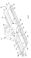
Figure 2 is a perspective view of the plunge saw upon the guide; -
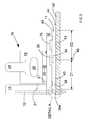
Figure 3 is an end view of the plunge saw and guide ofFigure 2 ; -
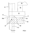
Figure 4 is an end view of detail A shown inFigure 3 ; -
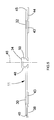
Figure 5 is an end view of the guide; -
Figure 6 is an underside view of a footplate of the plunge saw; -
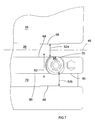
Figure 7 is cross-sectional view VII-VII inFigure 8 of an adjustable mechanism in the form of an eccentric element; -
Figure 8 is an end view of the footplate; -
Figure 9 is a perspective view of the eccentric element; -
Figure 10 is cross-sectional view X-X inFigure 8 of the eccentric element mounted upon the footplate; -
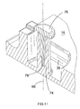
Figure 11 is the same cross-sectional view asFigure 10 without the eccentric element; -
Figure 12 is a perspective view of the plunge saw upon a second different guide; and -
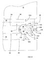
Figure 13 is a cross-sectional view VII-VII inFigure 8 with an alternative adjustment mechanism. - Referring to
Figure 1 to 4 , a hand-held tool in the form of aplunge saw 10 is designed to slide along aguide 11. The plunge saw comprises a motorisedcircular saw blade 12 and ablade guard 14. The blade and blade guard are both normally substantially perpendicular to afootplate 16, but may be adjusted to be inclined to the footplate for the purpose of bevel cutting. The plunge saw'sbody 18 is pitotable in a plane perpendicular to the footplate about ahinge 20 attached to the footplate. The blade can be moved between an upper "parked position" 12a inside the blade guard, and a lower "plunged position" 12b protruding below the footplate. The blade has anaxis 21 about which it rotates when turned by the motor. In use, the blade rotates in the direction of arrow W. Viewed from one end, as is best shown inFigure 1 , theaxis 21 follows an arc-shaped path BP as the blade moves between parked and plunged position. - The blade is biased into the parked position by a
spring 22. In use, a user can push the plunge saw downwardly, via a pair ofhandles position 12b. The exact depth of the plunged position is determined by setting a depth-stop (not shown). When the user releases the handles the blade springs back to the parkedposition 12a. - The user can also push the plunge saw forwardly, again via the handles, so that the footplate 14 slides along the
guide 11 to ensure that the blade cuts a straight line. The guide is made of strong material, like, for example, metal. Sliding motion is assisted by a pair of low-friction strips 30, 32 located on the upper surface of the guide. - The
guide 11 has astraight rail 34 on its upper surface and the footplate has a substantially correspondingly-shapedmiddle channel 36 in its lower surface. Engagement between rail and middle channel guides the footplate as it slides along the guide. In order to ensure a linear cut in the workpiece, the plunge saw 10 is positioned on theguide 11 which is placed upon the workpiece, rather than the plunge saw being positioned directly onto the workpiece. - A
guide lip 38, made of trimmable material, like, for example, hard rubber, is located beneath along side face 40 of the guide. When new, the guide lip is oversized to be wider than the distance X between aninner surface 112 of the blade and the long side face of the guide. The blade's first cut severs anouter margin 38a of the guide lip. What remains of the guide lip touches the blade. In other words, there is no gap between the bladeinner surface 112 and the guide lip. The guide lip is thereby matched to suit the blade which made the first cut. - There are at least two
anti-slip strips 43 on the underside of the guide. Each anti-slip strip has the same thickness as theguide lip 38 so that the guide is evenly supported when upon aworkpiece 42. - The region where guide lip, blade and workpiece meet is shown in detail in
Figure 4 . Downward pressure caused by the weight of the plunge saw and the guide is applied through the anti-slip strips and the guide lip upon the workpiece to hold the guide in place. The downward pressure at the guide lip provides downward support adjacent the blade which counteracts any tendency of the upward sweep of the rotating blade to splinter the upper surface of the workpiece in the region of the arrow B. This leads to a much cleaner cut in the workpiece. The downward pressure can be increased, if necessary, by clamping the guide to the workpiece. - Whenever the
blade 12 is replaced theguide lip 38 should, preferably, be renewed and matched to the replacement blade to ensure that a clean cut is mainatined. Spare guide lips can be easily fixed to the underside of the guide by adhesive. - A
second guide lip 44, also made of trimmable material, like, for example, hard rubber, is located on the oppositelong side face 45 of the guide. The second guide lip has the same thickness as theguide lip 38 and the rubber strips 43. - The
rail 34 is located in the centrallongitudinal plane 46 of the guide. Themiddle channel 36 is arranged so that when the plunge saw is rotated about 180° the blade overhangs the oppositelong side face 45 by approximately the same distance X to perform cutting action on that opposite side. The second guide lip is oversized to be wider than the distance X. The blade's first cut severs an outer margin of the second guide lip and what remains is thereby matched to the blade. - When the blade is replaced, but a spare guide lip is not available, or there is no time to renew it, the second guide lip can be used as a back-up resource. The plunge saw, or guide, is simply rotated through 180°.
- Alternatively, both guide lips can be deliberately matched to suit a particular blade so that both sides of a workpiece can be cut simply by rotating the plunge saw through 180°, rather than the rotating both the plunge saw and guide. This is an advantage when the guide is particularly long and cumbersome, like, for example, when several guides are coupled together.
- Periodically, the work environment dictates that an unsupported portion of a workpiece be cut. Whilst the
guide 11 is relatively strong it does, when unsupported, bow downwards under a bending moment caused by the weight of the plunge saw 10 resting thereupon. For example, when the user approaches the final stage of a cut the plunge saw rests upon an unsupported portion of the guide as it passes beyond the end of the workpiece. - Referring in particular to
Figure 3 , theguide 11 is substantially symmetrical when viewed from one end because the centrallongitudinal plane 46 bi-sects thecentral rail 34 of the otherwise planar guide i.e. distance D1 = distance D2. The guide tends to bow uniformly when unsupported with the plunge saw rested thereupon. The blade maintains its inclination with respect to the workpiece. Thus, provided that the distance bowed downward is not significant, an accurate cut can be finished without need to stop work and alter the guide's support system. - Referring to
Figure 5 , therail 34 has two outward facingsides longitudinal plane 46. - Referring to
Figure 6 , themiddle channel 36 includes thefirst parts - Referring to
Figures 7 and8 , the first part of dual-restriction 52a is defined, on the one hand, by an inward facing fixedside wall 56 in themiddle channel 36 and, on the other hand, by aneccentric element 58. The eccentric element may be rotated so that the width of the first part of dual-restriction 52a, measured in adirection 62 transverse to thelongitudinal plane 46, is adjusted. The first part of other dual-restriction 54a is also defined by a corresponding fixedside wall 56 and an identicaleccentric element 60. Theeccentric element 60 may also be rotated so that the width of the first part of other dual-restriction 54a, measured intransverse direction 62, is adjusted. Theeccentric elements - When the
footplate 16 is positioned on theguide 11 therail 34 passes through thefirst parts side wall 48 of therail 34 slides against the fixedface 56 in themiddle channel 36 and theopposite side wall 50 of therail 34 slides against theeccentric elements - Referring to
Figures 6 and7 , themiddle channel 36 has another inward facingside wall 64, opposite the fixedside wall 56, which is interrupted by theeccentric elements footplate 11 is guided only at thefirst parts side wall 56 and the interruptedside wall 64 is no longer significant, except that this distance must be greater, at least by a small amount, than the width of therail 34. - Since the widths of the
first parts transverse direction 62, the clearance betweenguide 11 and thefootplate 16 may be adjusted so that the footplate is guided without wobbling, as it were, in an exactly linear manner in the longitudinal direction. As such, it is also possible to compensate for manufacturing tolerances of the parts of the footplate. - When the
footplate 16 is positioned on theguide 11, the widths of thefirst parts eccentric elements rail 34 is located within themiddle channel 36 without clearance. - Note that, in principle, it would be sufficient to provide an adjustable dual-restriction at only one point along the channel, which would probably have to be located in the central region of the footplate. More than two such adjustable dual-restrictions may also be provided. However, two adjustable dual-restrictions, one located at each longitudinal end of the footplate's channel, is particularly expedient.
- Referring to
Figure 9 , eacheccentric element respective guide wheel 66, 67. Eacheccentric element rotation 68, 69. Both axes of rotation are perpendicular to the plane of the footplate. Each eccentric element has a cylindricalcircumferential surface 70, 71 which is eccentric to its respective axis ofrotation 68, 69. Rotation of a guide wheel by the plunge saw's user results in rotation of a respective eccentric element. - As is shown in
Figure 8 , rotation of theeccentric element 58 results in itscircumferential surface 70 selectively protruding, to a greater or lesser extent, through the interruptedside wall 64 and towards the fixedside wall 56. Accordingly, the width of thefirst part 52a of the dual-restriction, measured in thetransverse direction 62, is adjustable by rotation of theeccentric element 58. - In order to improve grip of the
guide wheels 66, 67, which are to be grasped manually, they may be provided on their outer circumference with a ribbing, or the like. Eacheccentric element -
Figures 10 and11 show how theeccentric element 58 is secured to a bearingportion 74 of the footplate 16 by a fixingbolt 76 passing through the middle of the eccentric element. The bearing portion has a threadedhole 78 into which the threaded fixingbolt 76 is screwed. The hole, the fixing bolt and the axis ofrotation 68 of the eccentric element are co-centric. To enable rotation of the eccentric element, the user unfastens the fixing bolt. When the eccentric element has been rotated to the extent necessary to adjust the width of the first 52a or second 52b parts of the dual-restriction, the user re-fastens the fixing bolt to immobilize the eccentric element against further rotation. Theeccentric element 60 is secured to a corresponding bearingportion 74 of the footplate in exactly the same way aseccentric element 58. - Referring to
Figures 8 and12 , thefootplate 16 also has aside channel 79 for engagement with arail 80 of analternative guide 82. Features of the alternative guide common with theguide 11 are numbered the same. However, the alternative guide is not symmetrical when viewed from one end because the rail is located on one side of the longitudinalcentral plane 46. Theguide 82 is stiffer in on the side of therail 80 and so it tends to bow in a skewed manner when unsupported. In these circumstances, the plunge saw and the blade will tilt to one side when the plunge saw is upon unsupported guide. The user must stop work and alter the support system of the guide to maintain an accurate cut. - In order to ensure a linear cut in the workpiece, the plunge saw 10 is positioned onto the
guide 82 which is placed upon the workpiece, rather than the plunge saw being placed directly onto the workpiece. Therail 80 has two outward facingside walls longitudinal plane 46. - Referring to
Figures 6 and7 , theside channel 79 includes thesecond parts side wall 88 in theside channel 79 and, on the other hand, by the sameeccentric element first parts middle channel 36. Eacheccentric element transverse direction 62, of the width of thesecond parts - When the
footplate 16 is positioned onto theguide 82 therail 80 passes through thesecond parts side 84 of therail 80 slides against the fixedside wall 88 of theside channel 60 and theopposite side 86 of therail 80 slides against theeccentric elements - Referring to
Figures 6 and7 , theside channel 79 has another inward facingside wall 90, opposite the fixedside wall 88, which is interrupted by theeccentric elements footplate 82 is guided only at thesecond parts side wall 88 and the interruptedside wall 90 is also not significant, except that this distance must be greater, at least by a small amount, than the width of therail 80. - Since the widths of the
second parts transverse direction 62, the clearance betweenguide 82 and thefootplate 16 may be adjusted so that the footplate is again guided without wobbling, as it were, in an exactly linear manner. - When the
footplate 16 is positioned on theguide 82, the widths of thesecond parts eccentric elements rail 80 is located within theside channel 79 without clearance. - The
eccentric elements circumferential surface 70, 71 of the eccentric element selectively protrudes, to a greater or lesser extent, through the interruptedside wall 90 and towards the fixedside wall 88, due to the eccentricity of the of the circumferential surface. Accordingly, the width of thesecond parts transverse direction 62, is also adjustable by rotation of theeccentric elements - Referring to
Figure 13 , an alternative to theeccentric elements adjustment mechanism 92. Like theeccentric elements side 79 channels. Only onealternative adjustment mechanism 92 is shown, but they both work in fundamentally the same way. - The alternative adjustment mechanisms each comprise two
pivot arms common pivot 100 located in thefootplate 16 so that an open mouth may be formed at the other ends of the arms. The arms are biased to pivot towards each other by a pair ofhelical springs 102. The helical springs can be substituted by anything capable of being located within the confines of the footplate, like, for example, a leaf spring or a rubber bush. - Each adjustment mechanism further comprises a
wedge 104 slideable along a straight track (not shown) in thefootplate 16 which is parallel to thelongitudinal plane 46. The wedge is controlled by a grub-screw 106 disposed in an adjacent end face of the footplate. The grub-screw cooperates with a threaded hole in 108 in the footplate. The track is aligned with the grub-screw and is directed towards the common pivot. The track ensures that the wedge is moveable back and forth between the arms but not laterally towards either of the central 36 and theside 79 channels. One end of the grub-screw engages amajor end face 110 of the wedge. Aminor end face 112 of the wedge is always disposed in the mouth between the arms. - Each
arm shoulder side 79 channels, respectively. When the grub-screw is driven by a screwdriver into the footplate the wedge forces the arms to pivot away from each other and against the bias of the springs. The shoulders thus protrude into the central 36 andside 79 channels the extent necessary to select the optimum width, measured in thetransverse direction 62, of thefirst part 52a and thesecond part 52b of the dual-restriction. - If clearance needs to be increased the grub-screw is driven out of the footplate to the extent necessary. The bias of the springs forces the wedge to follow the grub-screw so that the s arms pivot towards each other and the shoulders retract through the interrupted side faces 64, 90 of the central 36 and the
side 79 channels, respectively. - Re-adjustment to increase or decrease play may be performed whenever necessary.
Claims (15)
- A footplate (16) for a hand-held tool (10) for guiding the tool along a guide (11, 82), the footplate comprising on its lower surface at least one dual-restriction (52, 54), wherein the first part (52a, 54a) of the or each dual-restriction is for engaging a rail (34) extending in a longitudinal direction of a first guide (11) on the upper surface of said first guide and the second part (52b, 54b) of the or each dual-restriction is for engaging a rail (80) extending in a longitudinal direction of a second different guide (82) on the upper surface of said second guide, wherein the first and second parts of the or each dual-restriction each has a fixed side wall (56. 88), characterised in that the first and second parts of the or each dual-restriction have an adjustable side wall (70, 71, 114, 116) arranged opposite to a respective fixed side wall.
- A footplate (16) for a hand-held tool (10) as claimed in claim 1, wherein the width between the fixed and adjustable side walls, measured in a direction transverse (62) to the longitudinal direction, is adjustable by an adjustment mechanism (58, 60, 96, 98).
- A footplate (16) for a hand-held tool (10) as claimed in claim 2, wherein the adjustable side walls (70, 71, 114, 116) are located between the fixed side walls (56, 88).
- A footplate (16) for a hand-held tool (10) as claimed in claim 3, wherein the adjustment mechanism comprises a rotatable eccentric element (58, 60) located between the adjustable side walls (70, 71).
- A footplate (16) for a hand-held tool (10) as claimed in claim 4, wherein the adjustable side walls are opposing sides of a perimeter wall (70, 71) of the eccentric element.
- A footplate (16) for a hand-held tool (10) as claimed in claim 5, wherein the perimeter wall is a cylindrical wall arranged eccentrically in relation to the axis of rotation (68, 69) of the eccentric element.
- A footplate (16) for a hand-held tool (10) as claimed in any one of claims 4 to 6, wherein the eccentric element is secured to the footplate by a fixing bolt (76) connected to a bearing portion (74) of the footplate (16), wherein the fixing bolt can be unfastened or fastened to enable or disable rotation of the eccentric element, respectively.
- A footplate (16) for a hand-held tool (10) as claimed in any one of claims 4 to 7, wherein the adjustment mechanism comprises a manually accessible actuating member (66, 67) for rotating the eccentric element (58, 60).
- A footplate (16) for a hand-held tool (10) as claimed in any one of claims 4 to 8, wherein the eccentric element (58, 60) can be rotated about 360°.
- A footplate (16) for a hand-held tool (10) as claimed in claim 3, wherein the adjustment mechanism comprises two arms (96, 98), each arm arranged at one end to pivot about a common pivot point (100) so that an open mouth may be formed at the other ends of the arms, and a wedge (104) arranged to move within the mouth according to the position of a control device (106), whereby movement of the wedge into the mouth forces the arms to pivot apart to reduce the width between the fixed (56, 88) and adjustable (114, 116) side walls, and whereby movement of the wedge away from the mouth allows the arms to pivot closer to each other to increase the width between the fixed and adjustable side walls.
- A footplate (16) for a hand-held tool (10 as claimed in claim 10, wherein each arm (96, 98) has a shoulder (114, 116) and one shoulder protrudes away from the other shoulder in the transverse direction (62), whereby one shoulder is the adjustable side wall (114) of the first part (52a, 54a) of the dual-restriction and the other shoulder is the adjustable side wall (116) of the second part (52b, 54b) of the dual-restriction.
- A footplate for a hand-held tool as claimed in either one of claims 10 or 11, wherein the control device is a grub-screw (106) threadedly engaged with an externally accessible hole (108) in the footplate, whereby rotation of the grub-screw into the footplate moves the wedge (104) into the mouth and whereby rotation of the grub-screw out of the footplate allows the wedge to move out of the mouth.
- A footplate for a hand-held tool as claimed in any one of claims 10 to 12, wherein each arm is biased to pivot towards the other arm.
- A footplate for a hand-held tool substantially as described herein with reference to and as illustrated in the accompanying drawings Figures 1 to 12.
- A footplate for a hand-held tool substantially as described herein with reference to and as illustrated in the accompanying drawings Figures 1 to 5, 8, 12 and 13.
Priority Applications (5)
| Application Number | Priority Date | Filing Date | Title |
|---|---|---|---|
| EP20070113273 EP2018936B1 (en) | 2007-07-26 | 2007-07-26 | A footplate |
| DE200760007755 DE602007007755D1 (en) | 2007-07-26 | 2007-07-26 | footplate |
| AU2008203020A AU2008203020B2 (en) | 2007-07-26 | 2008-07-08 | A footplate |
| US12/171,408 US7856723B2 (en) | 2007-07-26 | 2008-07-11 | Footplate |
| CN2008101377921A CN101352812B (en) | 2007-07-26 | 2008-07-23 | A footplate |
Applications Claiming Priority (1)
| Application Number | Priority Date | Filing Date | Title |
|---|---|---|---|
| EP20070113273 EP2018936B1 (en) | 2007-07-26 | 2007-07-26 | A footplate |
Publications (2)
| Publication Number | Publication Date |
|---|---|
| EP2018936A1 true EP2018936A1 (en) | 2009-01-28 |
| EP2018936B1 EP2018936B1 (en) | 2010-07-14 |
Family
ID=38777958
Family Applications (1)
| Application Number | Title | Priority Date | Filing Date |
|---|---|---|---|
| EP20070113273 Not-in-force EP2018936B1 (en) | 2007-07-26 | 2007-07-26 | A footplate |
Country Status (5)
| Country | Link |
|---|---|
| US (1) | US7856723B2 (en) |
| EP (1) | EP2018936B1 (en) |
| CN (1) | CN101352812B (en) |
| AU (1) | AU2008203020B2 (en) |
| DE (1) | DE602007007755D1 (en) |
Cited By (2)
| Publication number | Priority date | Publication date | Assignee | Title |
|---|---|---|---|---|
| CN103418836A (en) * | 2013-08-02 | 2013-12-04 | 江苏苏美达五金工具有限公司 | Hand-held motor-operated electric tool with slide rail |
| EP4292742A1 (en) * | 2022-05-24 | 2023-12-20 | Black & Decker, Inc. | Power tool guide and power tool guide assembly |
Families Citing this family (15)
| Publication number | Priority date | Publication date | Assignee | Title |
|---|---|---|---|---|
| US20130118332A1 (en) * | 2010-07-21 | 2013-05-16 | Nicholas John Barnes | Portable variable-angle cutting guide |
| CN102380794B (en) * | 2010-08-27 | 2014-03-12 | 苏州宝时得电动工具有限公司 | Accessory of cutter |
| CN102814549B (en) * | 2011-06-07 | 2014-09-10 | 苏州宝时得电动工具有限公司 | Handheld cutting machine, guiding accessory for same and cutting system |
| US9156184B2 (en) * | 2012-03-26 | 2015-10-13 | Thomas Stoffel | Alignment device and method for aligning guide rails for a woodworking tool |
| DE102012218110B4 (en) * | 2012-10-04 | 2020-11-19 | Robert Bosch Gmbh | Management system |
| CN103419068B (en) * | 2013-07-15 | 2015-06-24 | 江苏苏美达五金工具有限公司 | Portable handheld circular saw |
| DE102013220188B4 (en) | 2013-10-07 | 2024-08-08 | Robert Bosch Gmbh | Hand tool guide device |
| US20160221091A1 (en) * | 2015-02-03 | 2016-08-04 | General Electric Company | Turbomachine blade ring segment cutting tool and related guide |
| DE102020100574B4 (en) | 2020-01-13 | 2024-02-08 | Festool Gmbh | Guide rail for guiding a hand-held machine tool |
| EP4171856B1 (en) * | 2020-06-25 | 2025-07-30 | Festool GmbH | Plunge saw with cut indicators and method of operating a plunge saw |
| US12263615B2 (en) | 2020-11-23 | 2025-04-01 | Milwaukee Electric Tool Corporation | Circular saw |
| US20230122037A1 (en) * | 2021-10-15 | 2023-04-20 | Affinity Tool Works, Llc | Rip guide |
| US12465982B2 (en) | 2022-02-24 | 2025-11-11 | Techtronic Cordless Gp | Track saw including plunge lockout mechanism |
| US20230382005A1 (en) * | 2022-05-26 | 2023-11-30 | Milwaukee Electric Tool Corporation | Track saw with movable splinter strip |
| US12083613B2 (en) | 2022-10-18 | 2024-09-10 | Techtronic Cordless Gp | Track saw including plunge lockout mechanism |
Citations (4)
| Publication number | Priority date | Publication date | Assignee | Title |
|---|---|---|---|---|
| DE3606525A1 (en) * | 1986-02-28 | 1987-09-03 | Lutz Eugen Masch | Guide device for portable electric tools |
| GB2204528A (en) * | 1987-05-11 | 1988-11-16 | Reich Maschf Gmbh Karl | Guide shoe for electric tools |
| DE20017862U1 (en) * | 2000-10-18 | 2001-02-08 | FESTO Tooltechnic GmbH & Co., 73728 Esslingen | Guide device for a machine tool |
| DE20101525U1 (en) * | 2001-01-30 | 2001-05-03 | Robert Bosch Gmbh, 70469 Stuttgart | Guide device for a hand machine tool, in particular for a hand-held circular saw |
Family Cites Families (22)
| Publication number | Priority date | Publication date | Assignee | Title |
|---|---|---|---|---|
| US2708465A (en) * | 1952-06-09 | 1955-05-17 | Floyd C Huebner | Guide clampable upon work for powered hand saws |
| US3298407A (en) * | 1964-07-30 | 1967-01-17 | Hugh A Scott | Clean cut saws |
| US3830130A (en) * | 1971-01-21 | 1974-08-20 | H Moore | Guide for portable power saws |
| US3903774A (en) * | 1974-01-04 | 1975-09-09 | Robert J Stinson | Cut-off attachment for a power hand saw |
| US4202233A (en) * | 1978-04-17 | 1980-05-13 | Larson Keith J | Saw guide device |
| US4224854A (en) * | 1978-09-01 | 1980-09-30 | Malacheski Joseph J | Sheet cutting and scoring device and method |
| AU5605080A (en) * | 1979-03-01 | 1980-09-04 | Cornelis Johannes Maria Beerens | Hand saw guide |
| DE8410794U1 (en) * | 1984-04-06 | 1985-10-03 | Robert Bosch Gmbh, 7000 Stuttgart | Guide device for a hand machine tool |
| US4751865A (en) * | 1986-04-17 | 1988-06-21 | Buckalew Joseph A | Self guiding portable saw with saw guide assembly |
| US5044075A (en) * | 1986-10-07 | 1991-09-03 | Sma Controls, Inc. | Boiler repair |
| GB2258188B (en) * | 1991-07-31 | 1994-05-11 | William Albery | Portable saws |
| US5333385A (en) * | 1993-04-27 | 1994-08-02 | Chou Chen Wen | Movable automatic sawing and clamping framework |
| US5509338A (en) * | 1994-01-27 | 1996-04-23 | Ekker; Shawn | Saw guide for cutting truss joist I-beams |
| US6062122A (en) * | 1998-04-20 | 2000-05-16 | Niemczyk; Gary | Cutting guide system for portable power saws |
| US6173631B1 (en) * | 1998-07-16 | 2001-01-16 | Stanton Jay Schock | Saw guide |
| US6712061B1 (en) * | 2001-02-20 | 2004-03-30 | Robert M. Kalb | Portable apparatus for working, shaping and polishing stone and other hard materials |
| US7621206B2 (en) * | 2002-06-24 | 2009-11-24 | Dino Makropoulos | Multi-function woodworking guide |
| US7610839B1 (en) * | 2002-11-25 | 2009-11-03 | Bessette Bernard J | Guide for the precise control of portable power tools |
| DE60302199T2 (en) * | 2002-12-10 | 2006-07-27 | Makita Corp., Anjo | cutting tool |
| US6868612B2 (en) * | 2003-07-18 | 2005-03-22 | Willard E. Ballard | Cutting guide device for circular saws |
| EP1842635B1 (en) * | 2005-06-01 | 2016-06-15 | Black & Decker, Inc. | Circular saw with anti-kickback device |
| JP4600184B2 (en) * | 2005-06-30 | 2010-12-15 | 日立工機株式会社 | Guide and portable cutting tool provided with the same |
-
2007
- 2007-07-26 DE DE200760007755 patent/DE602007007755D1/en active Active
- 2007-07-26 EP EP20070113273 patent/EP2018936B1/en not_active Not-in-force
-
2008
- 2008-07-08 AU AU2008203020A patent/AU2008203020B2/en not_active Ceased
- 2008-07-11 US US12/171,408 patent/US7856723B2/en not_active Expired - Fee Related
- 2008-07-23 CN CN2008101377921A patent/CN101352812B/en not_active Expired - Fee Related
Patent Citations (4)
| Publication number | Priority date | Publication date | Assignee | Title |
|---|---|---|---|---|
| DE3606525A1 (en) * | 1986-02-28 | 1987-09-03 | Lutz Eugen Masch | Guide device for portable electric tools |
| GB2204528A (en) * | 1987-05-11 | 1988-11-16 | Reich Maschf Gmbh Karl | Guide shoe for electric tools |
| DE20017862U1 (en) * | 2000-10-18 | 2001-02-08 | FESTO Tooltechnic GmbH & Co., 73728 Esslingen | Guide device for a machine tool |
| DE20101525U1 (en) * | 2001-01-30 | 2001-05-03 | Robert Bosch Gmbh, 70469 Stuttgart | Guide device for a hand machine tool, in particular for a hand-held circular saw |
Cited By (2)
| Publication number | Priority date | Publication date | Assignee | Title |
|---|---|---|---|---|
| CN103418836A (en) * | 2013-08-02 | 2013-12-04 | 江苏苏美达五金工具有限公司 | Hand-held motor-operated electric tool with slide rail |
| EP4292742A1 (en) * | 2022-05-24 | 2023-12-20 | Black & Decker, Inc. | Power tool guide and power tool guide assembly |
Also Published As
| Publication number | Publication date |
|---|---|
| CN101352812A (en) | 2009-01-28 |
| US20090049972A1 (en) | 2009-02-26 |
| US7856723B2 (en) | 2010-12-28 |
| AU2008203020A1 (en) | 2009-02-12 |
| AU2008203020B2 (en) | 2013-11-21 |
| CN101352812B (en) | 2012-05-23 |
| EP2018936B1 (en) | 2010-07-14 |
| DE602007007755D1 (en) | 2010-08-26 |
Similar Documents
| Publication | Publication Date | Title |
|---|---|---|
| EP2018936B1 (en) | A footplate | |
| US6920694B2 (en) | Saw with a tool guidance mechanism with guide elements adjustable to the tool size | |
| US8544372B2 (en) | Manual table saw and blade therefor | |
| US10744614B1 (en) | Adjustable sharpening apparatus and method for cutting implements | |
| EP2771148B1 (en) | Planer accessory tool for an oscillating power tool | |
| US5570511A (en) | Hand circular saw with swinging protective hood and cutting depth adjusting device | |
| US10131028B1 (en) | Adjustable sharpening apparatus and method for cutting implements | |
| US7156008B2 (en) | Flip-up multi-mode workpiece stop for miter saw | |
| US11052512B1 (en) | Adjustable knife sharpener and clamping assembly | |
| US4790072A (en) | Saw guide having pivotal protractor means | |
| US20090178531A1 (en) | Stationary, motor-driven underfloor saw | |
| EP2800653B1 (en) | Rolling guide for table saw | |
| US7127976B1 (en) | Guide for a cutting tool | |
| EP2412486A2 (en) | Guiding device and hand power tool with the same | |
| EP3348366A1 (en) | Cutting tool with adjustable cutting blade | |
| AU2017203420A1 (en) | Dual position blade guide for vertical or horizontal position of band saw | |
| US5454167A (en) | Portable saws | |
| US20060201297A1 (en) | Powered feed system for use with a machine saw table for providing guided motion along at least one axis | |
| KR102211833B1 (en) | Angle regulator for cutting worktable | |
| US10654188B2 (en) | Guide foot for an oscillating cutting tool | |
| US3927475A (en) | Saw guide | |
| EP2412487B1 (en) | Guiding device and hand power tool with the same | |
| KR20040078668A (en) | Device for cutting glass | |
| US20130139663A1 (en) | Panel saw and method of operation | |
| US20110185582A1 (en) | Power tool, especially hand-held power tool |
Legal Events
| Date | Code | Title | Description |
|---|---|---|---|
| PUAI | Public reference made under article 153(3) epc to a published international application that has entered the european phase |
Free format text: ORIGINAL CODE: 0009012 |
|
| AK | Designated contracting states |
Kind code of ref document: A1 Designated state(s): AT BE BG CH CY CZ DE DK EE ES FI FR GB GR HU IE IS IT LI LT LU LV MC MT NL PL PT RO SE SI SK TR |
|
| AX | Request for extension of the european patent |
Extension state: AL BA HR MK RS |
|
| 17P | Request for examination filed |
Effective date: 20090204 |
|
| 17Q | First examination report despatched |
Effective date: 20090304 |
|
| AKX | Designation fees paid |
Designated state(s): DE GB SE |
|
| GRAP | Despatch of communication of intention to grant a patent |
Free format text: ORIGINAL CODE: EPIDOSNIGR1 |
|
| GRAS | Grant fee paid |
Free format text: ORIGINAL CODE: EPIDOSNIGR3 |
|
| GRAA | (expected) grant |
Free format text: ORIGINAL CODE: 0009210 |
|
| AK | Designated contracting states |
Kind code of ref document: B1 Designated state(s): DE GB SE |
|
| REG | Reference to a national code |
Ref country code: GB Ref legal event code: FG4D |
|
| REF | Corresponds to: |
Ref document number: 602007007755 Country of ref document: DE Date of ref document: 20100826 Kind code of ref document: P |
|
| REG | Reference to a national code |
Ref country code: SE Ref legal event code: TRGR |
|
| PLBE | No opposition filed within time limit |
Free format text: ORIGINAL CODE: 0009261 |
|
| STAA | Information on the status of an ep patent application or granted ep patent |
Free format text: STATUS: NO OPPOSITION FILED WITHIN TIME LIMIT |
|
| 26N | No opposition filed |
Effective date: 20110415 |
|
| REG | Reference to a national code |
Ref country code: DE Ref legal event code: R097 Ref document number: 602007007755 Country of ref document: DE Effective date: 20110415 |
|
| PGFP | Annual fee paid to national office [announced via postgrant information from national office to epo] |
Ref country code: FI Payment date: 20180809 Year of fee payment: 17 |
|
| PGFP | Annual fee paid to national office [announced via postgrant information from national office to epo] |
Ref country code: GB Payment date: 20190724 Year of fee payment: 13 |
|
| REG | Reference to a national code |
Ref country code: SE Ref legal event code: EUG |
|
| PG25 | Lapsed in a contracting state [announced via postgrant information from national office to epo] |
Ref country code: SE Free format text: LAPSE BECAUSE OF NON-PAYMENT OF DUE FEES Effective date: 20190727 |
|
| PGFP | Annual fee paid to national office [announced via postgrant information from national office to epo] |
Ref country code: DE Payment date: 20200714 Year of fee payment: 14 |
|
| GBPC | Gb: european patent ceased through non-payment of renewal fee |
Effective date: 20200726 |
|
| PG25 | Lapsed in a contracting state [announced via postgrant information from national office to epo] |
Ref country code: GB Free format text: LAPSE BECAUSE OF NON-PAYMENT OF DUE FEES Effective date: 20200726 |
|
| REG | Reference to a national code |
Ref country code: DE Ref legal event code: R119 Ref document number: 602007007755 Country of ref document: DE |
|
| PG25 | Lapsed in a contracting state [announced via postgrant information from national office to epo] |
Ref country code: DE Free format text: LAPSE BECAUSE OF NON-PAYMENT OF DUE FEES Effective date: 20220201 |