EP2018328B1 - Closure - Google Patents
Closure Download PDFInfo
- Publication number
- EP2018328B1 EP2018328B1 EP07732869A EP07732869A EP2018328B1 EP 2018328 B1 EP2018328 B1 EP 2018328B1 EP 07732869 A EP07732869 A EP 07732869A EP 07732869 A EP07732869 A EP 07732869A EP 2018328 B1 EP2018328 B1 EP 2018328B1
- Authority
- EP
- European Patent Office
- Prior art keywords
- closure
- annular seal
- side wall
- neck opening
- annular
- Prior art date
- Legal status (The legal status is an assumption and is not a legal conclusion. Google has not performed a legal analysis and makes no representation as to the accuracy of the status listed.)
- Not-in-force
Links
Images


Classifications
-
- B—PERFORMING OPERATIONS; TRANSPORTING
- B65—CONVEYING; PACKING; STORING; HANDLING THIN OR FILAMENTARY MATERIAL
- B65D—CONTAINERS FOR STORAGE OR TRANSPORT OF ARTICLES OR MATERIALS, e.g. BAGS, BARRELS, BOTTLES, BOXES, CANS, CARTONS, CRATES, DRUMS, JARS, TANKS, HOPPERS, FORWARDING CONTAINERS; ACCESSORIES, CLOSURES, OR FITTINGS THEREFOR; PACKAGING ELEMENTS; PACKAGES
- B65D51/00—Closures not otherwise provided for
- B65D51/16—Closures not otherwise provided for with means for venting air or gas
- B65D51/1672—Closures not otherwise provided for with means for venting air or gas whereby venting occurs by manual actuation of the closure or other element
- B65D51/1688—Venting occurring during initial closing or opening of the container, by means of a passage for the escape of gas between the closure and the lip of the container mouth, e.g. interrupted threads
-
- B—PERFORMING OPERATIONS; TRANSPORTING
- B65—CONVEYING; PACKING; STORING; HANDLING THIN OR FILAMENTARY MATERIAL
- B65D—CONTAINERS FOR STORAGE OR TRANSPORT OF ARTICLES OR MATERIALS, e.g. BAGS, BARRELS, BOTTLES, BOXES, CANS, CARTONS, CRATES, DRUMS, JARS, TANKS, HOPPERS, FORWARDING CONTAINERS; ACCESSORIES, CLOSURES, OR FITTINGS THEREFOR; PACKAGING ELEMENTS; PACKAGES
- B65D41/00—Caps, e.g. crown caps or crown seals, i.e. members having parts arranged for engagement with the external periphery of a neck or wall defining a pouring opening or discharge aperture; Protective cap-like covers for closure members, e.g. decorative covers of metal foil or paper
- B65D41/02—Caps or cap-like covers without lines of weakness, tearing strips, tags, or like opening or removal devices
- B65D41/04—Threaded or like caps or cap-like covers secured by rotation
- B65D41/0407—Threaded or like caps or cap-like covers secured by rotation with integral sealing means
- B65D41/0414—Threaded or like caps or cap-like covers secured by rotation with integral sealing means formed by a plug, collar, flange, rib or the like contacting the internal surface of a container neck
- B65D41/0421—Threaded or like caps or cap-like covers secured by rotation with integral sealing means formed by a plug, collar, flange, rib or the like contacting the internal surface of a container neck and combined with integral sealing means contacting other surfaces of a container neck
-
- B—PERFORMING OPERATIONS; TRANSPORTING
- B65—CONVEYING; PACKING; STORING; HANDLING THIN OR FILAMENTARY MATERIAL
- B65D—CONTAINERS FOR STORAGE OR TRANSPORT OF ARTICLES OR MATERIALS, e.g. BAGS, BARRELS, BOTTLES, BOXES, CANS, CARTONS, CRATES, DRUMS, JARS, TANKS, HOPPERS, FORWARDING CONTAINERS; ACCESSORIES, CLOSURES, OR FITTINGS THEREFOR; PACKAGING ELEMENTS; PACKAGES
- B65D41/00—Caps, e.g. crown caps or crown seals, i.e. members having parts arranged for engagement with the external periphery of a neck or wall defining a pouring opening or discharge aperture; Protective cap-like covers for closure members, e.g. decorative covers of metal foil or paper
- B65D41/02—Caps or cap-like covers without lines of weakness, tearing strips, tags, or like opening or removal devices
- B65D41/04—Threaded or like caps or cap-like covers secured by rotation
- B65D41/0471—Threaded or like caps or cap-like covers secured by rotation with means for positioning the cap on the container, or for limiting the movement of the cap, or for preventing accidental loosening of the cap
-
- B—PERFORMING OPERATIONS; TRANSPORTING
- B65—CONVEYING; PACKING; STORING; HANDLING THIN OR FILAMENTARY MATERIAL
- B65D—CONTAINERS FOR STORAGE OR TRANSPORT OF ARTICLES OR MATERIALS, e.g. BAGS, BARRELS, BOTTLES, BOXES, CANS, CARTONS, CRATES, DRUMS, JARS, TANKS, HOPPERS, FORWARDING CONTAINERS; ACCESSORIES, CLOSURES, OR FITTINGS THEREFOR; PACKAGING ELEMENTS; PACKAGES
- B65D41/00—Caps, e.g. crown caps or crown seals, i.e. members having parts arranged for engagement with the external periphery of a neck or wall defining a pouring opening or discharge aperture; Protective cap-like covers for closure members, e.g. decorative covers of metal foil or paper
- B65D41/02—Caps or cap-like covers without lines of weakness, tearing strips, tags, or like opening or removal devices
- B65D41/04—Threaded or like caps or cap-like covers secured by rotation
- B65D41/0485—Threaded or like caps or cap-like covers secured by rotation with means specially adapted for facilitating the operation of opening or closing
Definitions
- the present invention relates generally to a closure for a container. More specifically, the invention relates to a closure made of plastics material for sealing a package containing, for example, a liquid.
- the invention is concerned particularly, but not exclusively, with closures which are for closing the opening of beverage containers, for example the necks of bottles made of glass or plastics material such as polypropylene or polyethylene terephthalate.
- Closure manufacturers have invested heavily in ongoing developments to provide closure designs which offer improved performance and/or reduced manufacturing costs.
- the main factors affecting closure performance include application and release torque, seal effectiveness and the reliability of tamper evidence.
- Plastic beverage closures generally feature four main components: a closure shell, a securing system, a sealing system and a tamper evidence system.
- the closure shell includes a circular top wall with a cylindrical side wall extending perpendicularly from the peripheral edge of the top wall.
- the securing system usually includes a snap on or screw thread design, both of which are known in the art, integrally formed with the cylindrical side wall on the inner surface thereof, which corresponds to a securing system adjacent to the container opening, for example the neck of a bottle.
- sealing system designs are known in the art and these will be discussed below.
- tamper evidence systems have also been developed, however, the most common design consists of a narrow band frangibly connected to the cylindrical side wall of the closure shell.
- the first main difference between plastic beverage closure designs is related to the sealing technology, wherein the sealing system is either integrally formed with the closure shell or a separate sealing system is inserted into the closure shell.
- the former is known as a one-piece closure whilst the latter is a two-piece closure design.
- closure seal design must ensure that the neck portion is hermetically sealed whilst minimising the torque required to remove and re-apply the closure. It will be appreciated that two-piece closure designs provide more design flexibility in that the closure shell may be formed using a high strength plastics material while the separate sealing system may be formed using a highly flexible material for improved sealing performance. However, it will also be appreciated that this arrangement may require a secondary manufacturing process for assembling the closure.
- US 6,779,672 discloses a one-piece closure design including three integrally formed protrusions extending from the inner surface of the top wall. These protrusions include inner and outer sealing protrusions for sealing against an inner and outer surface of the neck of the container respectively and one annular sealing ridge between the inner and outer sealing protrusions for sealing against the top surface of the neck.
- the inner and outer protrusions are shaped and spaced such that application of the closure on the container results in an interference fit thereby to provide a hermetically sealed container.
- the area of each protrusion which contacts the neck of the container comprises a narrow band, thereby concentrating the preload created by the deformation of the protrusions.
- EP 0,529,383 discloses a one-piece closure design having a bead, which is integrally formed with the side wall and top wall, and an outer sealing protrusion extending from the top wall for sealing against the top and outer surfaces of the neck as well as the radiused transition therebetween.
- a bead which is integrally formed with the side wall and top wall, and an outer sealing protrusion extending from the top wall for sealing against the top and outer surfaces of the neck as well as the radiused transition therebetween.
- application of the closure onto the container neck causes the outer sealing protrusion to deform to such an extent that the outer surface thereof contacts, and becomes contiguous with, the bead.
- This in turn causes the inner surface of the outer sealing protrusion to be urged against, and substantially take the shape of, the top and outer surfaces of the neck as well as the radiused transition therebetween.
- the bead provides rigidity to, and facilitates a large degree of plastic deformation of, the sealing protrusion. This arrangement provides a relatively large
- US 6,325,226 discloses a one-piece closure according to the preamble of claim 1, which utilises the outer sealing protrusion of EP 0,529,383 in conjunction with an inner sealing protrusion having a substantially olive cross section. Whilst this arrangement provides a sealing system which mitigates the issues discussed above in relation to US 6,779,672 , the effectiveness and/or manufacturability of the sealing system could be improved.
- a first aspect of the invention provides a one-piece closure for sealingly closing a neck opening of a container, the closure comprising a top wall, an annular side wall depending from the top wall and an annular seal having an inner surface and an outer surface facing the side wall, the annular side wall comprising a circular inner surface having a substantially constant diameter (d1) and extending from a lower end of the side wall to an upper end that connects with the top wall, the inner surface having securing features provided thereon for cooperably engaging features provided on the neck opening and the annular seal being deflectable by engagement between an inner surface thereof and the neck opening when, in use, the closure is fitted to the neck opening to a position in which the inner surface of the annular seal conforms to and is in close contact with the neck opening and the outer surface of the annular seal is pressed against the inner surface having a diameter (d1) by the neck opening.
- the securing features extend inwardly from the diameter (d1). More preferably, the side wall has a substantially constant radial thickness.
- the annular seal sealingly engages, in use, an outer surface of the neck opening whilst abutting the side wall.
- the top wall may have an outer peripheral portion that provides a radiused connection to the upper end of the annular side wall.
- the annular seal may extend at least in part from the outer peripheral portion. Additionally or alternatively, the annular seal may extend at least in part from an inner surface of the top wall.
- the annular seal may include an outer surface tapering away from the inner surface having a diameter (d1) and/or the annular seal may include a lead-in taper at the free end thereof.
- the annular seal may be shaped and dimensioned to sealingly engage the outer surface of the neck opening across a band whose width is at least one third of the overall length of the annular seal.
- the width may be at least one half of the length of the annular seal.
- the annular seal is preferably configured to deform to a greater extent, in use, in the region of the free end thereof than in the region thereof proximate to the top wall.
- the closure may further comprise an inner annular seal depending from the top wall which may sealingly engage, in use, an inner surface of the neck opening.
- the inner annular seal is preferably shaped to sealingly engage, in use, with the inner surface of the neck portion opening across a band whose width is less than the band of the annular seal that sealingly engages the outer surface of the neck opening.
- a portion of the inner annular seal proximate the free end thereof may comprise a substantially triangular cross-section whose apex faces the side wall.
- the apex may form the band that sealingly engages, in use, the inner surface of the neck opening.
- the free end of the inner annular seal may have a substantially olive shaped cross section.
- the closure may further comprise an annular sealing ridge depending from the top wall.
- the annular sealing ridge may be located between the outer and inner seals.
- the annular sealing ridge preferably sealingly engages, in use, a top surface of the neck opening.
- the annular sealing ridge may include an apex which sealingly engages, in use, the top surface of the neck opening.
- the annular sealing ridge is joined to the annular seal by a web portion.
- the securing features preferably protrude from an inner surface of the closure, for example from the side wall.
- the securing features may comprise at least one helical protrusion, for example a multi-start thread.
- the securing features may comprise interruptions therein.
- the securing features may further comprise a ridge for engaging a further ridge on the container, thereby to provide a snap fit.
- the closure may further comprise tamper evidence means, which may comprise a portion of the closure which is separated therefrom.
- the tamper evidence means may comprise a tamper evidence band and bridging elements which connect the tamper evidence band to the side wall of the closure.
- the closure may be sized and dimensioned such that, in use, the tamper evidence means cooperates with the neck opening such that the separable portion is separated from the closure, for example wherein the bridging elements are stressed and broken, as the annular seal disengages with the neck opening.
- the side wall preferably has an outer surface that has grip features provided thereon.
- the securing features may include anti slip members and portions of the annular seal engage the anti slip members when the annular seal is pressed against the inner surface having a diameter (d1).
- the closure may comprise tamper evidence means.
- a further aspect of the invention provides a container having a neck opening in combination with a closure according to the first, aspect of the invention.
- a further aspect of the invention provides a package comprising a container in combination with a closure according to the first and further aspects of the invention, wherein the container contains a liquid and is sealed by the closure.
- the closure of the invention may be designed such that it resembles a crown closure. It is also envisaged that the closure may be removed by similar means to a crown closure.
- Figures 1, 2 and 3 show a one-piece closure 1 including a top wall 2, a side wall 3, an outer peripheral portion 6, a tamper evidence band 4 and a sealing system 23, 24, 25.
- This embodiment of the invention is preferably injection moulded using high strength plastics material with sufficient flexibility for the sealing system to deform and function effectively.
- the plastics material may be, for example, high density polyethylene. It will be appreciated by those skilled in the art that the appearance of the closure of Figures 1 to 3 resembles substantially that of a "crown" closure.
- the top wall 2 is a circular disc of substantially constant wall thickness and includes an injection point 21 and a stiffening structure 22.
- the injection point 21, which results from the injection moulding process, is a substantially frusto-conical protrusion which protrudes from the top surface the top wall 2 at the centre thereof.
- the stiffening structure 22 includes a plurality of stiffening ribs, for example three ribs 22a, 22b, 22c, having a substantially dome shaped longitudinal cross-section, as shown in Figure 3 .
- stiffening ribs 22a, 22b, 22c are joined at their centres and are equiangularly spaced to provide the apexes of hexagram which protrudes from the inner surface of the top wall 2 at the centre thereof and opposite the injection point.
- the side wall 3 is a generally annular wall having a thickness that is substantially constant.
- the side wall 3 has an inner circular surface 30 that extends from the lower end of the side wall 3 to the upper end of the side wall 3.
- the surface 30 has a substantially constant diameter d1.
- a plurality of equispaced ribs 31 are integrally formed with the side wall 3.
- the ribs 31 protrude from the outer surface of the side wall 3 and extend in the axial direction thereof.
- An integrally formed securing means 32, 33 protrudes from the inner surface 30 of the side wall 3 and includes a plurality of interrupted helical protrusions 32 and anti-slip protrusions 33.
- the helical protrusions 32 form internal threads 32 having a common axis with the side wall 3 and have a substantially dome shaped axial cross-section as shown in Figure 3 .
- the threads 32 comprise a two-start thread arrangement.
- the anti-slip protrusions 33 extend axially along the side wall 3 and have a substantially dome shaped lateral cross-section. The width and depth of the anti-slip protrusions 33 both increase along the length thereof, the reasons for which are known in the art.
- the outer peripheral portion 6 is a cylindrical fillet segment defined by the outer periphery of the top wall 2. As shown in Figure 3 , the outer peripheral portion 6 has radial cross-section that provides a substantially orthogonal bend leading to the upper end of the side wall 3.
- the outer peripheral portion 6 has a plurality of equispaced rib extensions 31a provided on its outer surface.
- the spacing, width and depth of the rib extensions 31 a at the axially facing terminal edge of the bend are substantially the same as the spacing, width and depth of the ribs 31 which protrude from the side wall 3.
- the width and depth of the rib extensions 31 a both decrease toward the radially facing terminal edge of the bend to merge with the thickness of the fillet segment.
- the tamper evidence band 4 includes a substantially cylindrical wall 40, bridging elements 41 and retaining elements 42.
- the bridging elements 41 provide a frangible connection between the tamper evidence band 4 and the lower end of the side wall 3.
- the cylindrical wall 40 has an internal diameter which is substantially the same as the diameter d1 of the inner circular surface of the side wall 3 and a wall thickness which is less than that of the side wall 3.
- the bridging elements 41 extend from the axial upper edge of the cylindrical wall 40 of the tamper evidence band 4 to the lower end of the side wall 3 and have a wall thickness which is less than the thickness of the cylindrical wall 40.
- the retaining elements 42 protrude from the inner surface of the cylindrical wall 40 of the tamper evidence band 4 and are skewed in one direction, the reasons for which are known in the art.
- the sealing system 23, 24, 25 includes an annular seal 24 an inner annular seal 23 and an annular sealing ridge 25.
- the inner annular seal 23 includes a cylindrical wall which extends downwardly from, and is integrally formed with, the top wall 2.
- the inner annular seal 23 has an outwardly facing protrusion 26 proximate the free end thereof. But for the protrusions, the cross-sectional thickness of the inner annular seal 23 is substantially constant.
- the protrusion 26 has a substantially triangular cross-section with an outwardly facing apex, the reasons for which will be described below.
- the annular seal 24 includes a cylindrical wall which extends downwardly from, and is integrally formed with, the outer peripheral portion 6 and includes an outer surface which tapers away from the inner surface 30 of the side wall 3.
- the cross-sectional thickness of the annular seal 24 is substantially constant except that proximate the free end thereof it decreases to provide a lead-in taper 27, the reason for which will be explained below.
- the annular sealing ridge 25 is substantially triangular in cross-section with a downwardly facing apex.
- the annular sealing ridge 25 is located radially inwardly of the annular seal 24 and integrally formed therewith by a web portion 28.
- the annular sealing ridge 25 is adjacent the radially facing terminal edge of the outer peripheral portion 6. The reason for the shape and position of the annular sealing ridge 25 and the web portion 28 will be explained below.
- the side wall 3 is connected to, and integrally formed with, the outer peripheral portion 6 of the top wall 2 along the axially facing terminal edge of the outer peripheral portion 6 such that the rib extensions 31 a coincide with the ribs 31 so as to provide an uninterrupted extension thereof.
- the outer peripheral portion 6 provides a smooth transition between the top wall 2 and the side wall 3.
- the tamper evidence band 4 is frangibly connected to the bottom of the side wall 3 by the bridging elements 41, which are integrally formed therewith.
- Figures 4 and 5 show the neck portion 5 of a container for use with the closure 1 of Figures 1 to 3 .
- the neck portion 5 includes a substantially cylindrical body, an outer sealing rim 51, a plurality of interrupted helical protrusions 52, a tamper evidence ring 53 and a neck support ring 54.
- the cylindrical body includes a top sealing surface 55 and an inner sealing surface 56.
- the outer sealing rim 51 is an annular ring which has substantially constant width and depth and protrudes from the outer surface of the cylindrical body adjacent the top sealing surface 55 and blended therewith by a fillet segment 57.
- the helical protrusions 52 have a substantially dome shaped axial cross section and protrude from the outer surface of the cylindrical body below the outer sealing rim 51.
- the helical protrusions 52 form external threads 52 having a common axis with the cylindrical body.
- the tamper evidence ring 53 has an arcuate axial cross-section with a flat bottom surface, a geometry which is known in the art.
- the tamper evidence ring 53 protrudes from the outer surface of the cylindrical body of the neck portion 5 below the external threads 52.
- the neck support ring 54 is substantially frusto-conical in shape with a flat bottom surface, a geometry which is also known in the art.
- the neck support ring 54 protrudes from the outer surface of the cylindrical body of the neck portion 5 below the tamper evidence ring 53.
- Applying the closure 1 to the container also causes the retaining elements 42 of the tamper evidence band 4 to engage the tamper evidence ring 53 of the neck portion 5.
- the retaining elements 42 contact the upper arcuate surface of the tamper evidence ring 53 of the neck portion 5. Further rotation of the closure 1 causes the tamper evidence band 4 to deflect outwardly until the retaining elements 42 pass over the tamper evidence ring 53 and the tamper evidence band 4 reverts to its original shape.
- Removal of the closure 1 also causes the retaining elements 42 to contact the lower generally horizontal underside 60 of the tamper evidence ring 53. Further rotation of the closure causes the bridging elements 41 to be stressed and broken thereby separating the tamper evidence band 4 from the side wall 3. The separation of the tamper evidence band 4 from the closure provides a positive indication that the seal has been compromised.
- the stressing and breaking of the bridging elements 41 and the disengagement of the sealing system 23, 24, 25 with the neck portion 5 occur at substantially the same time.
- This feature is particularly useful in cases where the contents of the container are pressurised in that the bridging elements 41 help to retain the closure 1 on the neck portion 5 as the contents start to vent whilst still providing a reliable indicator of tamper evidence. In such a case, venting is facilitated by the aforementioned interruptions in the threads 32, 52.
- by having the bridging elements break as the venting occurs, rather than having venting occur ahead of breaking of the tamper evidence band it is possible to reduce the height of the closure, thereby reducing the material requirements for the manufacture of the closure.
- the resilient nature of the plastics material causes the sealing system 23, 24, 25 to revert substantially to its original shape.
- the large degree of deformation of the annular seal 24, which ensures an effective seal, will result in some plastic deformation thus precluding it from reverting to its exact original shape.
- the design and position of the sealing system 23, 24, 25 relative to the side wall 3 ensures the seal is effective on subsequent application of the closure. The result is a closure design with good resealability, allowing the container to be hermetically sealed upon repeated application and removal of the closure 1 to the neck portion 5.
- the arrangement disclosed herein provides an effective and reliable sealing structure.
- Several aspects of the closure design contribute to this including, but not limited to, the position of the annular seal 24 causing it to abut and inner surface of the side wall 3 on application of the closure; the fact that the annular seal 24 extends from the outer peripheral portion 6; the presence of the web portion 28 which joins the annular seal 24 and the annular sealing ridge 25 and other aspects which are apparent from the above disclosure, some of which are included in the claims.
- These aspects result a reinforced structure having sufficient flexibility to provide an effective seal both on initial application and further reapplication of the closure.
- the configuration of the closure 1 allows for a mould design that is simpler and less conducive to wear and/or damage during production than many prior art closure designs.
- the substantially constant wall thickness of the side wall 3 adjacent the outer peripheral portion 6 and/or the absence of thickening protrusions on the inner surface 30 of the side wall facilitates cooling during the moulding process.
- the sealing system design reduces the need to thin regions of mould cores as compared with known comparable closure designs.
- the annular seal 24 may be formed in part on the generally planar underside of the top wall 2 and in part on the inner surface of the outer peripheral portion 6.
- the length and geometry of the outer sealing protrusion 24 may be altered, for example by tapering outwardly instead of inwardly toward the terminal edge thereof, or it may be lengthened or shortened as required for a given application.
- the web portion 28 may be thicker, thinner or dispensed with.
- the injection point 21 may be located in a recess on the top surface of the top wall 2.
- the geometry of the contact surfaces may be modified to provide a wider or narrower band than that shown in the drawings, for example the inner annular seal 23 may comprise an end portion which is substantially olive in shape.
- the anti-slip protrusions 33 are optional and may not be desirable for certain applications.
- the securing means 32 may be replaced with any suitable arrangement for retaining the closure on a container.
- a snap-on type securing means may be used.
- the securing means may be incorporated into the sealing system without departing from the scope of the invention, for example by providing a recessed inner sealing surface which retains the inner annular seal 23.
- the securing means may protrude from an outer surface of the side wall 3.
- the closure may be sized and dimensioned such that it may be removed with crown closure removal means known in the art, for example a bottle opener.
- crown closure removal means known in the art, for example a bottle opener.
- the securing means may be in the form of a snap on finish and the overall height of the closure reduced to allow for removal using, for example, a bottle opener.
- the closure may be manufactured using a compression moulding process, for example with a secondary process of slitting the perforations which define the frangible connection between the cylindrical side wall 3 and the tamper evidence band.
- closure provides the possibility of reducing the amount of material required to manufacture of the closure as compared with known closures.
- the sealing system arranged to break the seal with the neck of the container at substantially the same time as the tamper evidence band breaks, it is possible to reduce amount of controlled movement the means securing the closure to the container must provide, so allowing the overall height of the closure and neck portion to be reduced.
- the outer annular seal of the closure by arranging for the outer annular seal of the closure to deflect and engage the start, it is possible to reduce the thickness of the seal, since it is supported by the side wall 3 when providing the seal. By having the outer annular seal directly engage the side wall 3 rather than providing a bead or other contact protrusions provided on the side wall 3, further material savings can be made.
Landscapes
- Engineering & Computer Science (AREA)
- Mechanical Engineering (AREA)
- Closures For Containers (AREA)
- Specific Sealing Or Ventilating Devices For Doors And Windows (AREA)
- Separation By Low-Temperature Treatments (AREA)
- Formation And Processing Of Food Products (AREA)
- Developing Agents For Electrophotography (AREA)
- Glass Compositions (AREA)
Abstract
Description
- The present invention relates generally to a closure for a container. More specifically, the invention relates to a closure made of plastics material for sealing a package containing, for example, a liquid. The invention is concerned particularly, but not exclusively, with closures which are for closing the opening of beverage containers, for example the necks of bottles made of glass or plastics material such as polypropylene or polyethylene terephthalate.
- Closure manufacturers have invested heavily in ongoing developments to provide closure designs which offer improved performance and/or reduced manufacturing costs. The main factors affecting closure performance include application and release torque, seal effectiveness and the reliability of tamper evidence.
- It is known to provide closures made of plastics material for beverage containers. The use of plastics material for closures offers a number of advantages both in terms of manufacturing costs and closure performance, particularly in the area of sealing technology.
- Plastic beverage closures generally feature four main components: a closure shell, a securing system, a sealing system and a tamper evidence system. The closure shell includes a circular top wall with a cylindrical side wall extending perpendicularly from the peripheral edge of the top wall. The securing system usually includes a snap on or screw thread design, both of which are known in the art, integrally formed with the cylindrical side wall on the inner surface thereof, which corresponds to a securing system adjacent to the container opening, for example the neck of a bottle. Several sealing system designs are known in the art and these will be discussed below. Several tamper evidence systems have also been developed, however, the most common design consists of a narrow band frangibly connected to the cylindrical side wall of the closure shell.
- The first main difference between plastic beverage closure designs is related to the sealing technology, wherein the sealing system is either integrally formed with the closure shell or a separate sealing system is inserted into the closure shell. The former is known as a one-piece closure whilst the latter is a two-piece closure design.
- An effective closure seal design must ensure that the neck portion is hermetically sealed whilst minimising the torque required to remove and re-apply the closure. It will be appreciated that two-piece closure designs provide more design flexibility in that the closure shell may be formed using a high strength plastics material while the separate sealing system may be formed using a highly flexible material for improved sealing performance. However, it will also be appreciated that this arrangement may require a secondary manufacturing process for assembling the closure.
- One example of a two-piece closure design is disclosed in
US 6,783,015 wherein a liner insert engages the closure shell and provides a seal between the top wall and the end face of the container. - In an effort to simplify the manufacturing process, single piece closures have been developed to eliminate the need for the secondary process of inserting a separate liner. An early example of one such closure is disclosed in
GB 2,013,635 - Single piece closure sealing technology is constantly under development. The use of a single material for the closure shell and sealing system gives rise to difficulties in establishing the balance between a structure which is strong enough to maintain the structural integrity of the shell whilst providing an effective seal in use. To this end, several closure designs have been developed in order to optimise the balance between these two factors.
- For example,
US 6,779,672 discloses a one-piece closure design including three integrally formed protrusions extending from the inner surface of the top wall. These protrusions include inner and outer sealing protrusions for sealing against an inner and outer surface of the neck of the container respectively and one annular sealing ridge between the inner and outer sealing protrusions for sealing against the top surface of the neck. The inner and outer protrusions are shaped and spaced such that application of the closure on the container results in an interference fit thereby to provide a hermetically sealed container. The area of each protrusion which contacts the neck of the container comprises a narrow band, thereby concentrating the preload created by the deformation of the protrusions. Despite the advantages of such an arrangement, the narrow bands of contact between the sealing system and the neck may result in a less effective seal if the neck of the container is damaged at the contact area, for example during manufacture or transport. -
EP 0,529,383 discloses a one-piece closure design having a bead, which is integrally formed with the side wall and top wall, and an outer sealing protrusion extending from the top wall for sealing against the top and outer surfaces of the neck as well as the radiused transition therebetween. In use, application of the closure onto the container neck causes the outer sealing protrusion to deform to such an extent that the outer surface thereof contacts, and becomes contiguous with, the bead. This in turn causes the inner surface of the outer sealing protrusion to be urged against, and substantially take the shape of, the top and outer surfaces of the neck as well as the radiused transition therebetween. The bead provides rigidity to, and facilitates a large degree of plastic deformation of, the sealing protrusion. This arrangement provides a relatively large contact surface area, which mitigates the effect of any surface damage and improves resealability upon reapplication. -
US 6,325,226 discloses a one-piece closure according to the preamble ofclaim 1, which utilises the outer sealing protrusion ofEP 0,529,383 in conjunction with an inner sealing protrusion having a substantially olive cross section. Whilst this arrangement provides a sealing system which mitigates the issues discussed above in relation toUS 6,779,672 , the effectiveness and/or manufacturability of the sealing system could be improved. - A first aspect of the invention provides a one-piece closure for sealingly closing a neck opening of a container, the closure comprising a top wall, an annular side wall depending from the top wall and an annular seal having an inner surface and an outer surface facing the side wall, the annular side wall comprising a circular inner surface having a substantially constant diameter (d1) and extending from a lower end of the side wall to an upper end that connects with the top wall, the inner surface having securing features provided thereon for cooperably engaging features provided on the neck opening and the annular seal being deflectable by engagement between an inner surface thereof and the neck opening when, in use, the closure is fitted to the neck opening to a position in which the inner surface of the annular seal conforms to and is in close contact with the neck opening and the outer surface of the annular seal is pressed against the inner surface having a diameter (d1) by the neck opening. Preferably, the securing features extend inwardly from the diameter (d1). More preferably, the side wall has a substantially constant radial thickness.
- The annular seal sealingly engages, in use, an outer surface of the neck opening whilst abutting the side wall.
- The top wall may have an outer peripheral portion that provides a radiused connection to the upper end of the annular side wall. The annular seal may extend at least in part from the outer peripheral portion. Additionally or alternatively, the annular seal may extend at least in part from an inner surface of the top wall.
- The annular seal may include an outer surface tapering away from the inner surface having a diameter (d1) and/or the annular seal may include a lead-in taper at the free end thereof.
- The annular seal may be shaped and dimensioned to sealingly engage the outer surface of the neck opening across a band whose width is at least one third of the overall length of the annular seal. The width may be at least one half of the length of the annular seal.
- The annular seal is preferably configured to deform to a greater extent, in use, in the region of the free end thereof than in the region thereof proximate to the top wall.
- The closure may further comprise an inner annular seal depending from the top wall which may sealingly engage, in use, an inner surface of the neck opening. The inner annular seal is preferably shaped to sealingly engage, in use, with the inner surface of the neck portion opening across a band whose width is less than the band of the annular seal that sealingly engages the outer surface of the neck opening.
- A portion of the inner annular seal proximate the free end thereof may comprise a substantially triangular cross-section whose apex faces the side wall. The apex may form the band that sealingly engages, in use, the inner surface of the neck opening.
- Alternatively, the free end of the inner annular seal may have a substantially olive shaped cross section.
- The closure may further comprise an annular sealing ridge depending from the top wall. The annular sealing ridge may be located between the outer and inner seals. The annular sealing ridge preferably sealingly engages, in use, a top surface of the neck opening. The annular sealing ridge may include an apex which sealingly engages, in use, the top surface of the neck opening. Optionally, the annular sealing ridge is joined to the annular seal by a web portion.
- The securing features preferably protrude from an inner surface of the closure, for example from the side wall. The securing features may comprise at least one helical protrusion, for example a multi-start thread. The securing features may comprise interruptions therein.
- Alternatively, the securing features may further comprise a ridge for engaging a further ridge on the container, thereby to provide a snap fit.
- The closure may further comprise tamper evidence means, which may comprise a portion of the closure which is separated therefrom. For example, the tamper evidence means may comprise a tamper evidence band and bridging elements which connect the tamper evidence band to the side wall of the closure. The closure may be sized and dimensioned such that, in use, the tamper evidence means cooperates with the neck opening such that the separable portion is separated from the closure, for example wherein the bridging elements are stressed and broken, as the annular seal disengages with the neck opening.
- The side wall preferably has an outer surface that has grip features provided thereon.
- The securing features may include anti slip members and portions of the annular seal engage the anti slip members when the annular seal is pressed against the inner surface having a diameter (d1).
- The closure may comprise tamper evidence means.
- A further aspect of the invention provides a container having a neck opening in combination with a closure according to the first, aspect of the invention.
- A further aspect of the invention provides a package comprising a container in combination with a closure according to the first and further aspects of the invention, wherein the container contains a liquid and is sealed by the closure.
- The closure of the invention may be designed such that it resembles a crown closure. It is also envisaged that the closure may be removed by similar means to a crown closure.
- Exemplary embodiments of the invention will now be described, by way of example only, with reference to the accompanying drawings in which:
-
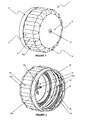
Figure 1 is a perspective view showing the side and top of a closure; -
Figure 2 is a perspective view showing the side and bottom of the closure ofFigure 1 ; -
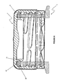
Figure 3 is a cross-sectional view of the closure ofFigure 1 through the centre of the closure showing the sealing system; -
Figure 4 is a perspective view of the top and side of the neck opening of a container for use with the closure ofFigure 1 ; -
Figure 5 is a side view of the neck portion of the container ofFigure 4 ; -
Figure 6 is a cross-sectional view of the closure ofFigure 1 applied to the neck portion ofFigure 4 showing the deformation of the sealing system. -
Figures 1, 2 and3 show a one-piece closure 1 including atop wall 2, aside wall 3, an outerperipheral portion 6, atamper evidence band 4 and asealing system Figures 1 to 3 resembles substantially that of a "crown" closure. - In the preferred embodiment the
top wall 2 is a circular disc of substantially constant wall thickness and includes aninjection point 21 and a stiffeningstructure 22. Theinjection point 21, which results from the injection moulding process, is a substantially frusto-conical protrusion which protrudes from the top surface thetop wall 2 at the centre thereof. The stiffeningstructure 22 includes a plurality of stiffening ribs, for example threeribs Figure 3 . The stiffeningribs top wall 2 at the centre thereof and opposite the injection point. - The
side wall 3 is a generally annular wall having a thickness that is substantially constant. Theside wall 3 has an innercircular surface 30 that extends from the lower end of theside wall 3 to the upper end of theside wall 3. Thesurface 30 has a substantially constant diameter d1. A plurality ofequispaced ribs 31 are integrally formed with theside wall 3. Theribs 31 protrude from the outer surface of theside wall 3 and extend in the axial direction thereof. An integrally formed securing means 32, 33 protrudes from theinner surface 30 of theside wall 3 and includes a plurality of interruptedhelical protrusions 32 andanti-slip protrusions 33. Thehelical protrusions 32 forminternal threads 32 having a common axis with theside wall 3 and have a substantially dome shaped axial cross-section as shown inFigure 3 . In the preferred embodiment, thethreads 32 comprise a two-start thread arrangement. Theanti-slip protrusions 33 extend axially along theside wall 3 and have a substantially dome shaped lateral cross-section. The width and depth of theanti-slip protrusions 33 both increase along the length thereof, the reasons for which are known in the art. - In this embodiment, the outer
peripheral portion 6 is a cylindrical fillet segment defined by the outer periphery of thetop wall 2. As shown inFigure 3 , the outerperipheral portion 6 has radial cross-section that provides a substantially orthogonal bend leading to the upper end of theside wall 3. The outerperipheral portion 6 has a plurality ofequispaced rib extensions 31a provided on its outer surface. The spacing, width and depth of therib extensions 31 a at the axially facing terminal edge of the bend are substantially the same as the spacing, width and depth of theribs 31 which protrude from theside wall 3. The width and depth of therib extensions 31 a both decrease toward the radially facing terminal edge of the bend to merge with the thickness of the fillet segment. - In this embodiment, the
tamper evidence band 4 includes a substantiallycylindrical wall 40, bridgingelements 41 and retainingelements 42. The bridgingelements 41 provide a frangible connection between thetamper evidence band 4 and the lower end of theside wall 3. Thecylindrical wall 40 has an internal diameter which is substantially the same as the diameter d1 of the inner circular surface of theside wall 3 and a wall thickness which is less than that of theside wall 3. The bridgingelements 41 extend from the axial upper edge of thecylindrical wall 40 of thetamper evidence band 4 to the lower end of theside wall 3 and have a wall thickness which is less than the thickness of thecylindrical wall 40. In this embodiment the retainingelements 42 protrude from the inner surface of thecylindrical wall 40 of thetamper evidence band 4 and are skewed in one direction, the reasons for which are known in the art. In this embodiment, the sealingsystem annular seal 24 an innerannular seal 23 and anannular sealing ridge 25. - The inner
annular seal 23 includes a cylindrical wall which extends downwardly from, and is integrally formed with, thetop wall 2. The innerannular seal 23 has an outwardly facingprotrusion 26 proximate the free end thereof. But for the protrusions, the cross-sectional thickness of the innerannular seal 23 is substantially constant. Theprotrusion 26 has a substantially triangular cross-section with an outwardly facing apex, the reasons for which will be described below. - The
annular seal 24 includes a cylindrical wall which extends downwardly from, and is integrally formed with, the outerperipheral portion 6 and includes an outer surface which tapers away from theinner surface 30 of theside wall 3. The cross-sectional thickness of theannular seal 24 is substantially constant except that proximate the free end thereof it decreases to provide a lead-intaper 27, the reason for which will be explained below. - The
annular sealing ridge 25 is substantially triangular in cross-section with a downwardly facing apex. Theannular sealing ridge 25 is located radially inwardly of theannular seal 24 and integrally formed therewith by aweb portion 28. Theannular sealing ridge 25 is adjacent the radially facing terminal edge of the outerperipheral portion 6. The reason for the shape and position of theannular sealing ridge 25 and theweb portion 28 will be explained below. - The
side wall 3 is connected to, and integrally formed with, the outerperipheral portion 6 of thetop wall 2 along the axially facing terminal edge of the outerperipheral portion 6 such that therib extensions 31 a coincide with theribs 31 so as to provide an uninterrupted extension thereof. The outerperipheral portion 6 provides a smooth transition between thetop wall 2 and theside wall 3. Thetamper evidence band 4 is frangibly connected to the bottom of theside wall 3 by the bridgingelements 41, which are integrally formed therewith. -
Figures 4 and 5 show theneck portion 5 of a container for use with theclosure 1 ofFigures 1 to 3 . Theneck portion 5 includes a substantially cylindrical body, anouter sealing rim 51, a plurality of interruptedhelical protrusions 52, atamper evidence ring 53 and aneck support ring 54. - The cylindrical body includes a
top sealing surface 55 and aninner sealing surface 56. The outer sealing rim 51 is an annular ring which has substantially constant width and depth and protrudes from the outer surface of the cylindrical body adjacent thetop sealing surface 55 and blended therewith by afillet segment 57. Thehelical protrusions 52 have a substantially dome shaped axial cross section and protrude from the outer surface of the cylindrical body below theouter sealing rim 51. Thehelical protrusions 52 formexternal threads 52 having a common axis with the cylindrical body. - The
tamper evidence ring 53 has an arcuate axial cross-section with a flat bottom surface, a geometry which is known in the art. Thetamper evidence ring 53 protrudes from the outer surface of the cylindrical body of theneck portion 5 below theexternal threads 52. Theneck support ring 54 is substantially frusto-conical in shape with a flat bottom surface, a geometry which is also known in the art. Theneck support ring 54 protrudes from the outer surface of the cylindrical body of theneck portion 5 below thetamper evidence ring 53. - Referring particularly to
Figure 6 , in use and on application of theclosure 1 to theneck portion 5, clockwise rotation of the closure 1 (as seen from the top thereof) causes theinternal threads 32 of theclosure 1 to mesh with theexternal threads 52 of theneck portion 5. This, in turn, drives thetop wall 2 of theclosure 1 toward thetop sealing surface 55 of theneck portion 5 causing the sealingsystem neck portion 5. - As the
top wall 2 approaches thetop sealing surface 55 of theneck portion 5, a lower portion of thetriangular protrusion 26 of the innerannular seal 23 contacts the radiused corner between thetop sealing surface 55 and theinner sealing surface 56 of theneck portion 5. Further rotation of theclosure 1 causes the innerannular seal 23 to deflect inwardly until the apex of thetriangular protrusion 26 comes into close contact with theinner sealing surface 56 of theneck portion 5. This arrangement results in a resilient engagement with theneck portion 5 providing an inner seal over a narrow band which corresponds to the deformed apex of thetriangular protrusion 26. - As the
closure 1 is rotated further, the lead-intaper 27 of theannular seal 24 contacts thefillet segment 57 between thetop sealing surface 55 and the outer sealing rim 51 of theneck portion 5. Further rotation of theclosure 1 causes theannular seal 24 to deflect outwardly until a lower portion thereof contacts the innercircular surface 30 of theside wall 3. This arrangement forces theannular seal 24 to deform such that a substantial portion of the inner surface thereof conforms to, and is in close contact with, theouter sealing rim 51 and a substantial portion of the outer surface thereof conforms to the innercircular surface 30 of theside wall 3. This arrangement results in an outer seal over a relatively wide band which corresponds to a substantial portion of the length of theannular seal 24, for example more than one third thereof. - Further rotation of the
closure 1 causes the apex of theannular sealing ridge 25 to come into close contact with thetop sealing surface 55 and deform thereby to provide a top seal. This arrangement results in a top seal over a narrow band which corresponds to the deformed apex of theannular sealing ridge 25. - Applying the
closure 1 to the container also causes the retainingelements 42 of thetamper evidence band 4 to engage thetamper evidence ring 53 of theneck portion 5. As theclosure 1 is applied, the retainingelements 42 contact the upper arcuate surface of thetamper evidence ring 53 of theneck portion 5. Further rotation of theclosure 1 causes thetamper evidence band 4 to deflect outwardly until the retainingelements 42 pass over thetamper evidence ring 53 and thetamper evidence band 4 reverts to its original shape. - On removal of the
closure 1, counter-clockwise rotation thereof causes thethreads top wall 2 of theclosure 1 from thetop sealing surface 55 of theneck portion 5. This results in the disengagement of the sealingsystem neck portion 5, corresponding substantially to the reverse of the steps outlined above. - Removal of the
closure 1 also causes the retainingelements 42 to contact the lower generally horizontal underside 60 of thetamper evidence ring 53. Further rotation of the closure causes thebridging elements 41 to be stressed and broken thereby separating thetamper evidence band 4 from theside wall 3. The separation of thetamper evidence band 4 from the closure provides a positive indication that the seal has been compromised. - The stressing and breaking of the
bridging elements 41 and the disengagement of the sealingsystem neck portion 5 occur at substantially the same time. This feature is particularly useful in cases where the contents of the container are pressurised in that the bridgingelements 41 help to retain theclosure 1 on theneck portion 5 as the contents start to vent whilst still providing a reliable indicator of tamper evidence. In such a case, venting is facilitated by the aforementioned interruptions in thethreads - The resilient nature of the plastics material, high density polyethylene in the case of this embodiment, causes the
sealing system annular seal 24, which ensures an effective seal, will result in some plastic deformation thus precluding it from reverting to its exact original shape. The design and position of the sealingsystem side wall 3 ensures the seal is effective on subsequent application of the closure. The result is a closure design with good resealability, allowing the container to be hermetically sealed upon repeated application and removal of theclosure 1 to theneck portion 5. - It will be appreciated that the arrangement disclosed herein provides an effective and reliable sealing structure. Several aspects of the closure design contribute to this including, but not limited to, the position of the
annular seal 24 causing it to abut and inner surface of theside wall 3 on application of the closure; the fact that theannular seal 24 extends from the outerperipheral portion 6; the presence of theweb portion 28 which joins theannular seal 24 and theannular sealing ridge 25 and other aspects which are apparent from the above disclosure, some of which are included in the claims. These aspects result a reinforced structure having sufficient flexibility to provide an effective seal both on initial application and further reapplication of the closure. - Furthermore, it will be appreciated that the two-start thread arrangement requires less torque for application and removal of the closure.
- It will also be appreciated by those skilled in the art that the configuration of the
closure 1 allows for a mould design that is simpler and less conducive to wear and/or damage during production than many prior art closure designs. In particular, the substantially constant wall thickness of theside wall 3 adjacent the outerperipheral portion 6 and/or the absence of thickening protrusions on theinner surface 30 of the side wall facilitates cooling during the moulding process. Moreover, the sealing system design reduces the need to thin regions of mould cores as compared with known comparable closure designs. - Further embodiments are envisaged without departing from the scope of the invention. For example, the
annular seal 24 may be formed in part on the generally planar underside of thetop wall 2 and in part on the inner surface of the outerperipheral portion 6. The length and geometry of theouter sealing protrusion 24 may be altered, for example by tapering outwardly instead of inwardly toward the terminal edge thereof, or it may be lengthened or shortened as required for a given application. Theweb portion 28 may be thicker, thinner or dispensed with. Theinjection point 21 may be located in a recess on the top surface of thetop wall 2. The geometry of the contact surfaces may be modified to provide a wider or narrower band than that shown in the drawings, for example the innerannular seal 23 may comprise an end portion which is substantially olive in shape. - The
anti-slip protrusions 33 are optional and may not be desirable for certain applications. The securing means 32 may be replaced with any suitable arrangement for retaining the closure on a container. For example a snap-on type securing means may be used. Moreover, it is envisaged that the securing means may be incorporated into the sealing system without departing from the scope of the invention, for example by providing a recessed inner sealing surface which retains the innerannular seal 23. Alternatively, the securing means may protrude from an outer surface of theside wall 3. - The closure may be sized and dimensioned such that it may be removed with crown closure removal means known in the art, for example a bottle opener. For example, the securing means may be in the form of a snap on finish and the overall height of the closure reduced to allow for removal using, for example, a bottle opener.
- The closure may be manufactured using a compression moulding process, for example with a secondary process of slitting the perforations which define the frangible connection between the
cylindrical side wall 3 and the tamper evidence band. - It will be understood that various features of the closure provide the possibility of reducing the amount of material required to manufacture of the closure as compared with known closures. As noted above, by having the sealing system arranged to break the seal with the neck of the container at substantially the same time as the tamper evidence band breaks, it is possible to reduce amount of controlled movement the means securing the closure to the container must provide, so allowing the overall height of the closure and neck portion to be reduced. Furthermore, by arranging for the outer annular seal of the closure to deflect and engage the start, it is possible to reduce the thickness of the seal, since it is supported by the
side wall 3 when providing the seal. By having the outer annular seal directly engage theside wall 3 rather than providing a bead or other contact protrusions provided on theside wall 3, further material savings can be made.
Claims (15)
- A one-piece closure (1) for sealingly closing a neck opening of a container, the closure (1) comprising a top wall (2), an annular side wall (3) depending from the top wall (2) and an annular seal (24) having an inner surface and an outer surface facing the side wall (3), the annular side wall (3) comprising a circular inner surface having a substantially constant diameter (d1) and extending from a lower end of the side wall (3) to an upper end that connects with the top wall (2), the inner surface having securing features (32,33) provided thereon for cooperably engaging features (52) provided on the neck opening and the annular seal (24) being deflectable by engagement between an inner surface thereof and the neck opening when, in use, the closure (1) is fitted to the neck opening to a position in which the inner surface of the annular seal (24) conforms to and is in close contact with the neck opening characterised in that the outer surface of the annular seal (24) is pressed against the inner surface having the said substantially constant diameter (d1) by the neck opening.
- A closure (1) as claimed in Claim 1, wherein the securing features (32,33) extend inwardly from the inner surface having the substantially constant diameter (d1).
- A closure (1) as claimed in Claim 1 or Claim 2, wherein the side wall (3) has a substantially constant radial thickness.
- A closure (1) as claimed in any preceding Claim, wherein the top wall (2) has an outer peripheral portion that provides a radiused connection to the upper end of the annular side wall (3).
- A closure (1) as claimed in Claim 4, wherein the annular seal (24) extends at least in part from the outer peripheral portion.
- A closure (1) as claimed in any preceding Claim, wherein the annular seal (24) extends at least in part from an inner surface of the top wall (2)
- A closure (1) as claimed in any preceding Claim, wherein the annular seal (24) includes an outer surface tapering away from the inner surface having a diameter (d1).
- A closure (1) as claimed in any preceding Claim, wherein the annular seal (24) includes a lead-in taper (27) at the free end thereof.
- A closure (1) as claimed in any preceding Claim, further comprising an inner annular seal (23) depending from the top wall (2), which inner annular seal (23) preferably engages, in use, an inner surface of the neck opening.
- A closure (1) as claimed in any preceding Claim, further comprising an annular sealing ridge (25) depending from the top wall (2), wherein the annular sealing ridge (25) preferably includes an apex which sealingly engages, in use, the top surface of the neck opening.
- A closure (1) as claimed in Claim 10, wherein the annular sealing ridge (25) is joined to the annular seal by a web portion (28).
- A closure (1) as claimed in any preceding Claim, further comprising tamper evidence means (4) which preferably comprises a portion of the closure (1) which is separable therefrom.
- A container having a neck opening in combination with a closure (1) as claimed in any one of the preceding Claims.
- A container in combination with a closure (1) as claimed in Claim 12 and 13, wherein the closure (1) is sized and dimensioned such that, in use the tamper evidence means (4) cooperates with the neck opening such that the separable portion (4) is separated from the closure (1) as the annular seal (24) disengages from the neck opening.
- A package comprising a container in combination with a closure (1) as claimed in Claim 13 or Claim 14, wherein the container contains a liquid and is sealed by the closure (1).
Applications Claiming Priority (2)
| Application Number | Priority Date | Filing Date | Title |
|---|---|---|---|
| GBGB0609802.4A GB0609802D0 (en) | 2006-05-17 | 2006-05-17 | Closure |
| PCT/GB2007/001847 WO2007132254A1 (en) | 2006-05-17 | 2007-05-17 | Closure |
Publications (2)
| Publication Number | Publication Date |
|---|---|
| EP2018328A1 EP2018328A1 (en) | 2009-01-28 |
| EP2018328B1 true EP2018328B1 (en) | 2011-08-03 |
Family
ID=36660342
Family Applications (1)
| Application Number | Title | Priority Date | Filing Date |
|---|---|---|---|
| EP07732869A Not-in-force EP2018328B1 (en) | 2006-05-17 | 2007-05-17 | Closure |
Country Status (6)
| Country | Link |
|---|---|
| US (1) | US20090301986A1 (en) |
| EP (1) | EP2018328B1 (en) |
| AT (1) | ATE518772T1 (en) |
| DK (1) | DK2018328T3 (en) |
| GB (1) | GB0609802D0 (en) |
| WO (1) | WO2007132254A1 (en) |
Families Citing this family (18)
| Publication number | Priority date | Publication date | Assignee | Title |
|---|---|---|---|---|
| US20090045158A1 (en) * | 2007-08-14 | 2009-02-19 | Alcoa Closure Systems International, Inc. | Threaded closure with internal ribs |
| GB2467355A (en) | 2009-01-30 | 2010-08-04 | Beeson & Sons Ltd | Container closure with pressure seal |
| US20110100947A1 (en) * | 2009-11-02 | 2011-05-05 | Long Charles J | Anti-Backoff Closure |
| EP2481679A4 (en) * | 2010-01-12 | 2015-05-06 | Chwei-Jei Tsai | Pet bottle lid and manufacturing method thereof |
| JP6055418B2 (en) * | 2010-12-17 | 2016-12-27 | ノバルティス アーゲー | Pressure relief container for sterilization and storage of contact lenses and method of treating contact lenses |
| USD664835S1 (en) * | 2011-01-10 | 2012-08-07 | W.K. Wu Products Inc. | Wall hook |
| PL2720959T3 (en) * | 2011-06-14 | 2019-05-31 | Closure Systems Int Inc | Closure |
| JP5977937B2 (en) * | 2011-11-21 | 2016-08-24 | 株式会社Csiジャパン | Synthetic resin cap for carbonated beverage filling container, closure device, and beverage closure device |
| US8443999B1 (en) * | 2012-04-16 | 2013-05-21 | Robert C. Reinders | Cap, cap/container combination |
| USD722689S1 (en) * | 2012-05-01 | 2015-02-17 | Tri State Distribution, Inc. | Segmented threads for a pharmaceutical cap |
| USD711739S1 (en) * | 2013-03-07 | 2014-08-26 | Apothecary Products, Llc | Push tab vial cover |
| JP6456216B2 (en) * | 2015-02-27 | 2019-01-23 | 株式会社吉野工業所 | Threaded cap container |
| FR3041941B1 (en) * | 2015-10-01 | 2017-11-10 | United Caps France | CAP WITH EVENTS |
| USD824027S1 (en) * | 2016-01-13 | 2018-07-24 | MRI Interventions, Inc. | Fins for a support column for a surgical trajectory frame |
| KR102478408B1 (en) * | 2017-06-15 | 2022-12-15 | 키스코 가부시키가이샤 | volatilization container |
| US10919670B1 (en) * | 2017-12-21 | 2021-02-16 | Gervasio A. Chicaia | Tamperproof seal for sealing containers |
| WO2021041123A1 (en) * | 2019-08-27 | 2021-03-04 | Runway Blue, Llc | Anti-cross-threading thread configuration |
| US12703541B2 (en) | 2024-08-30 | 2026-08-11 | Closure Systems International Inc. | Closure with plug and container |
Family Cites Families (10)
| Publication number | Priority date | Publication date | Assignee | Title |
|---|---|---|---|---|
| FR2327930A1 (en) * | 1975-10-13 | 1977-05-13 | Alca Sa | Plastics sealing cap for screw top bottle - has flexible lip to form seal on outer rim of bottle neck and inner lips to seal bottle opening |
| EP0076778A1 (en) * | 1981-10-05 | 1983-04-13 | Crown Obrist AG | Closure of plastics material |
| US4442947A (en) * | 1983-01-18 | 1984-04-17 | Continental White Cap, Inc. | Plastic closure with sealing flaps |
| US5638972A (en) * | 1988-06-17 | 1997-06-17 | Druitt; Rodney Malcolm | Linerless closure for carbonated beverage container |
| DE19705717A1 (en) * | 1997-02-14 | 1998-08-20 | Bericap Gmbh & Co Kg | Plastic screw cap |
| US20020074306A1 (en) * | 1997-02-14 | 2002-06-20 | Gunter Krautkramer | Plastic screw closure |
| AUPO788597A0 (en) * | 1997-07-14 | 1997-08-07 | Closures And Packaging Services Limited | Closure |
| KR20010096600A (en) * | 2000-03-13 | 2001-11-07 | 도케 케이시 | Synthetic resin container closure |
| US6695161B2 (en) * | 2001-02-08 | 2004-02-24 | Japan Crown Cork Co., Ltd. | Plastic container closure |
| CA2540734C (en) * | 2003-10-01 | 2011-12-13 | Obrist Closures Switzerland Gmbh | A closure |
-
2006
- 2006-05-17 GB GBGB0609802.4A patent/GB0609802D0/en not_active Ceased
-
2007
- 2007-05-17 AT AT07732869T patent/ATE518772T1/en not_active IP Right Cessation
- 2007-05-17 EP EP07732869A patent/EP2018328B1/en not_active Not-in-force
- 2007-05-17 US US12/300,991 patent/US20090301986A1/en not_active Abandoned
- 2007-05-17 DK DK07732869.8T patent/DK2018328T3/en active
- 2007-05-17 WO PCT/GB2007/001847 patent/WO2007132254A1/en not_active Ceased
Also Published As
| Publication number | Publication date |
|---|---|
| WO2007132254A1 (en) | 2007-11-22 |
| EP2018328A1 (en) | 2009-01-28 |
| GB0609802D0 (en) | 2006-06-28 |
| DK2018328T3 (en) | 2011-11-21 |
| US20090301986A1 (en) | 2009-12-10 |
| ATE518772T1 (en) | 2011-08-15 |
Similar Documents
| Publication | Publication Date | Title |
|---|---|---|
| US20090301986A1 (en) | Closure | |
| JP3574445B2 (en) | Lid for tamper evident | |
| EP2627570B1 (en) | Improved tamper-evident closure and package | |
| JP5291175B2 (en) | Synthetic resin container lid and combination of container lid and container | |
| EP0815028B1 (en) | Tamper-evident closure with captive band | |
| US4741447A (en) | Linerless cap closure | |
| US6779672B2 (en) | Synthetic resin container closure | |
| EP3661856B1 (en) | Closure | |
| US8485374B2 (en) | Plastic closure with enhanced performance | |
| US20090045158A1 (en) | Threaded closure with internal ribs | |
| US20030230546A1 (en) | Sports beverage snap closure | |
| US6260721B1 (en) | Plastic cap | |
| US11753215B2 (en) | Container closure of synthetic resin | |
| JPH0210024B2 (en) | ||
| EP0381118B1 (en) | Tamper-indicating plastic closure | |
| GB2323593A (en) | Self-threading closure/container assembly | |
| CN114929589A (en) | Synthetic resin container lid | |
| US6068151A (en) | Tamper-indicating plastic closure having pilfer band | |
| US20030121880A1 (en) | Method of injection molding closure with continuous internal rigid rib, closure made thereby having a lead-in structure and mold for forming same | |
| JP2007137482A (en) | Resin cap | |
| US6568548B1 (en) | Closure with tamper-indicating band | |
| EP1492713B1 (en) | Container screw-closure cap | |
| JP3875421B2 (en) | Can with temporary sealing stopper | |
| CN114051481A (en) | Hinge closure | |
| JPH0442255B2 (en) |
Legal Events
| Date | Code | Title | Description |
|---|---|---|---|
| PUAI | Public reference made under article 153(3) epc to a published international application that has entered the european phase |
Free format text: ORIGINAL CODE: 0009012 |
|
| 17P | Request for examination filed |
Effective date: 20081110 |
|
| AK | Designated contracting states |
Kind code of ref document: A1 Designated state(s): AT BE BG CH CY CZ DE DK EE ES FI FR GB GR HU IE IS IT LI LT LU LV MC MT NL PL PT RO SE SI SK TR |
|
| AX | Request for extension of the european patent |
Extension state: AL BA HR MK RS |
|
| GRAP | Despatch of communication of intention to grant a patent |
Free format text: ORIGINAL CODE: EPIDOSNIGR1 |
|
| DAX | Request for extension of the european patent (deleted) | ||
| GRAS | Grant fee paid |
Free format text: ORIGINAL CODE: EPIDOSNIGR3 |
|
| GRAA | (expected) grant |
Free format text: ORIGINAL CODE: 0009210 |
|
| AK | Designated contracting states |
Kind code of ref document: B1 Designated state(s): AT BE BG CH CY CZ DE DK EE ES FI FR GB GR HU IE IS IT LI LT LU LV MC MT NL PL PT RO SE SI SK TR |
|
| REG | Reference to a national code |
Ref country code: GB Ref legal event code: FG4D |
|
| REG | Reference to a national code |
Ref country code: CH Ref legal event code: EP |
|
| REG | Reference to a national code |
Ref country code: IE Ref legal event code: FG4D |
|
| REG | Reference to a national code |
Ref country code: DE Ref legal event code: R096 Ref document number: 602007016279 Country of ref document: DE Effective date: 20110929 |
|
| REG | Reference to a national code |
Ref country code: SE Ref legal event code: TRGR |
|
| REG | Reference to a national code |
Ref country code: NL Ref legal event code: T3 |
|
| REG | Reference to a national code |
Ref country code: DK Ref legal event code: T3 |
|
| LTIE | Lt: invalidation of european patent or patent extension |
Effective date: 20110803 |
|
| PG25 | Lapsed in a contracting state [announced via postgrant information from national office to epo] |
Ref country code: IS Free format text: LAPSE BECAUSE OF FAILURE TO SUBMIT A TRANSLATION OF THE DESCRIPTION OR TO PAY THE FEE WITHIN THE PRESCRIBED TIME-LIMIT Effective date: 20111203 Ref country code: LT Free format text: LAPSE BECAUSE OF FAILURE TO SUBMIT A TRANSLATION OF THE DESCRIPTION OR TO PAY THE FEE WITHIN THE PRESCRIBED TIME-LIMIT Effective date: 20110803 Ref country code: PT Free format text: LAPSE BECAUSE OF FAILURE TO SUBMIT A TRANSLATION OF THE DESCRIPTION OR TO PAY THE FEE WITHIN THE PRESCRIBED TIME-LIMIT Effective date: 20111205 Ref country code: FI Free format text: LAPSE BECAUSE OF FAILURE TO SUBMIT A TRANSLATION OF THE DESCRIPTION OR TO PAY THE FEE WITHIN THE PRESCRIBED TIME-LIMIT Effective date: 20110803 |
|
| REG | Reference to a national code |
Ref country code: AT Ref legal event code: MK05 Ref document number: 518772 Country of ref document: AT Kind code of ref document: T Effective date: 20110803 |
|
| PG25 | Lapsed in a contracting state [announced via postgrant information from national office to epo] |
Ref country code: PL Free format text: LAPSE BECAUSE OF FAILURE TO SUBMIT A TRANSLATION OF THE DESCRIPTION OR TO PAY THE FEE WITHIN THE PRESCRIBED TIME-LIMIT Effective date: 20110803 Ref country code: GR Free format text: LAPSE BECAUSE OF FAILURE TO SUBMIT A TRANSLATION OF THE DESCRIPTION OR TO PAY THE FEE WITHIN THE PRESCRIBED TIME-LIMIT Effective date: 20111104 Ref country code: SI Free format text: LAPSE BECAUSE OF FAILURE TO SUBMIT A TRANSLATION OF THE DESCRIPTION OR TO PAY THE FEE WITHIN THE PRESCRIBED TIME-LIMIT Effective date: 20110803 Ref country code: AT Free format text: LAPSE BECAUSE OF FAILURE TO SUBMIT A TRANSLATION OF THE DESCRIPTION OR TO PAY THE FEE WITHIN THE PRESCRIBED TIME-LIMIT Effective date: 20110803 Ref country code: CY Free format text: LAPSE BECAUSE OF FAILURE TO SUBMIT A TRANSLATION OF THE DESCRIPTION OR TO PAY THE FEE WITHIN THE PRESCRIBED TIME-LIMIT Effective date: 20110803 Ref country code: LV Free format text: LAPSE BECAUSE OF FAILURE TO SUBMIT A TRANSLATION OF THE DESCRIPTION OR TO PAY THE FEE WITHIN THE PRESCRIBED TIME-LIMIT Effective date: 20110803 |
|
| PG25 | Lapsed in a contracting state [announced via postgrant information from national office to epo] |
Ref country code: CZ Free format text: LAPSE BECAUSE OF FAILURE TO SUBMIT A TRANSLATION OF THE DESCRIPTION OR TO PAY THE FEE WITHIN THE PRESCRIBED TIME-LIMIT Effective date: 20110803 Ref country code: SK Free format text: LAPSE BECAUSE OF FAILURE TO SUBMIT A TRANSLATION OF THE DESCRIPTION OR TO PAY THE FEE WITHIN THE PRESCRIBED TIME-LIMIT Effective date: 20110803 |
|
| PG25 | Lapsed in a contracting state [announced via postgrant information from national office to epo] |
Ref country code: IT Free format text: LAPSE BECAUSE OF FAILURE TO SUBMIT A TRANSLATION OF THE DESCRIPTION OR TO PAY THE FEE WITHIN THE PRESCRIBED TIME-LIMIT Effective date: 20110803 Ref country code: RO Free format text: LAPSE BECAUSE OF FAILURE TO SUBMIT A TRANSLATION OF THE DESCRIPTION OR TO PAY THE FEE WITHIN THE PRESCRIBED TIME-LIMIT Effective date: 20110803 Ref country code: EE Free format text: LAPSE BECAUSE OF FAILURE TO SUBMIT A TRANSLATION OF THE DESCRIPTION OR TO PAY THE FEE WITHIN THE PRESCRIBED TIME-LIMIT Effective date: 20110803 |
|
| PLBE | No opposition filed within time limit |
Free format text: ORIGINAL CODE: 0009261 |
|
| STAA | Information on the status of an ep patent application or granted ep patent |
Free format text: STATUS: NO OPPOSITION FILED WITHIN TIME LIMIT |
|
| 26N | No opposition filed |
Effective date: 20120504 |
|
| REG | Reference to a national code |
Ref country code: DE Ref legal event code: R097 Ref document number: 602007016279 Country of ref document: DE Effective date: 20120504 |
|
| BERE | Be: lapsed |
Owner name: CONSTAR INTERNATIONAL INC. Effective date: 20120531 |
|
| REG | Reference to a national code |
Ref country code: NL Ref legal event code: V1 Effective date: 20121201 |
|
| PG25 | Lapsed in a contracting state [announced via postgrant information from national office to epo] |
Ref country code: MC Free format text: LAPSE BECAUSE OF NON-PAYMENT OF DUE FEES Effective date: 20120531 |
|
| REG | Reference to a national code |
Ref country code: CH Ref legal event code: PL |
|
| REG | Reference to a national code |
Ref country code: SE Ref legal event code: EUG |
|
| REG | Reference to a national code |
Ref country code: DK Ref legal event code: EBP |
|
| GBPC | Gb: european patent ceased through non-payment of renewal fee |
Effective date: 20120517 |
|
| PG25 | Lapsed in a contracting state [announced via postgrant information from national office to epo] |
Ref country code: CH Free format text: LAPSE BECAUSE OF NON-PAYMENT OF DUE FEES Effective date: 20120531 Ref country code: LI Free format text: LAPSE BECAUSE OF NON-PAYMENT OF DUE FEES Effective date: 20120531 |
|
| REG | Reference to a national code |
Ref country code: IE Ref legal event code: MM4A |
|
| PG25 | Lapsed in a contracting state [announced via postgrant information from national office to epo] |
Ref country code: BE Free format text: LAPSE BECAUSE OF NON-PAYMENT OF DUE FEES Effective date: 20120531 Ref country code: SE Free format text: LAPSE BECAUSE OF NON-PAYMENT OF DUE FEES Effective date: 20120518 |
|
| REG | Reference to a national code |
Ref country code: FR Ref legal event code: ST Effective date: 20130131 |
|
| REG | Reference to a national code |
Ref country code: DE Ref legal event code: R119 Ref document number: 602007016279 Country of ref document: DE Effective date: 20121201 |
|
| PG25 | Lapsed in a contracting state [announced via postgrant information from national office to epo] |
Ref country code: NL Free format text: LAPSE BECAUSE OF NON-PAYMENT OF DUE FEES Effective date: 20121201 |
|
| PG25 | Lapsed in a contracting state [announced via postgrant information from national office to epo] |
Ref country code: FR Free format text: LAPSE BECAUSE OF NON-PAYMENT OF DUE FEES Effective date: 20120531 Ref country code: IE Free format text: LAPSE BECAUSE OF NON-PAYMENT OF DUE FEES Effective date: 20120517 Ref country code: ES Free format text: LAPSE BECAUSE OF FAILURE TO SUBMIT A TRANSLATION OF THE DESCRIPTION OR TO PAY THE FEE WITHIN THE PRESCRIBED TIME-LIMIT Effective date: 20111114 Ref country code: GB Free format text: LAPSE BECAUSE OF NON-PAYMENT OF DUE FEES Effective date: 20120517 Ref country code: DK Free format text: LAPSE BECAUSE OF NON-PAYMENT OF DUE FEES Effective date: 20120531 |
|
| PG25 | Lapsed in a contracting state [announced via postgrant information from national office to epo] |
Ref country code: BG Free format text: LAPSE BECAUSE OF FAILURE TO SUBMIT A TRANSLATION OF THE DESCRIPTION OR TO PAY THE FEE WITHIN THE PRESCRIBED TIME-LIMIT Effective date: 20111103 Ref country code: DE Free format text: LAPSE BECAUSE OF NON-PAYMENT OF DUE FEES Effective date: 20121201 |
|
| PG25 | Lapsed in a contracting state [announced via postgrant information from national office to epo] |
Ref country code: MT Free format text: LAPSE BECAUSE OF FAILURE TO SUBMIT A TRANSLATION OF THE DESCRIPTION OR TO PAY THE FEE WITHIN THE PRESCRIBED TIME-LIMIT Effective date: 20110803 |
|
| PG25 | Lapsed in a contracting state [announced via postgrant information from national office to epo] |
Ref country code: TR Free format text: LAPSE BECAUSE OF FAILURE TO SUBMIT A TRANSLATION OF THE DESCRIPTION OR TO PAY THE FEE WITHIN THE PRESCRIBED TIME-LIMIT Effective date: 20110803 |
|
| PG25 | Lapsed in a contracting state [announced via postgrant information from national office to epo] |
Ref country code: LU Free format text: LAPSE BECAUSE OF NON-PAYMENT OF DUE FEES Effective date: 20120517 |
|
| PG25 | Lapsed in a contracting state [announced via postgrant information from national office to epo] |
Ref country code: HU Free format text: LAPSE BECAUSE OF FAILURE TO SUBMIT A TRANSLATION OF THE DESCRIPTION OR TO PAY THE FEE WITHIN THE PRESCRIBED TIME-LIMIT Effective date: 20070517 |