EP2018290B1 - Axle drive and clutch device for a motor vehicle - Google Patents
Axle drive and clutch device for a motor vehicle Download PDFInfo
- Publication number
- EP2018290B1 EP2018290B1 EP07724714A EP07724714A EP2018290B1 EP 2018290 B1 EP2018290 B1 EP 2018290B1 EP 07724714 A EP07724714 A EP 07724714A EP 07724714 A EP07724714 A EP 07724714A EP 2018290 B1 EP2018290 B1 EP 2018290B1
- Authority
- EP
- European Patent Office
- Prior art keywords
- switching
- shaft
- axle drive
- drive according
- sliding sleeve
- Prior art date
- Legal status (The legal status is an assumption and is not a legal conclusion. Google has not performed a legal analysis and makes no representation as to the accuracy of the status listed.)
- Not-in-force
Links
Images


Classifications
-
- F—MECHANICAL ENGINEERING; LIGHTING; HEATING; WEAPONS; BLASTING
- F16—ENGINEERING ELEMENTS AND UNITS; GENERAL MEASURES FOR PRODUCING AND MAINTAINING EFFECTIVE FUNCTIONING OF MACHINES OR INSTALLATIONS; THERMAL INSULATION IN GENERAL
- F16H—GEARING
- F16H63/00—Control outputs from the control unit to change-speed- or reversing-gearings for conveying rotary motion or to other devices than the final output mechanism
- F16H63/02—Final output mechanisms therefor; Actuating means for the final output mechanisms
- F16H63/30—Constructional features of the final output mechanisms
- F16H63/304—Constructional features of the final output mechanisms the final output mechanisms comprising elements moved by electrical or magnetic force
-
- B—PERFORMING OPERATIONS; TRANSPORTING
- B60—VEHICLES IN GENERAL
- B60K—ARRANGEMENT OR MOUNTING OF PROPULSION UNITS OR OF TRANSMISSIONS IN VEHICLES; ARRANGEMENT OR MOUNTING OF PLURAL DIVERSE PRIME-MOVERS IN VEHICLES; AUXILIARY DRIVES FOR VEHICLES; INSTRUMENTATION OR DASHBOARDS FOR VEHICLES; ARRANGEMENTS IN CONNECTION WITH COOLING, AIR INTAKE, GAS EXHAUST OR FUEL SUPPLY OF PROPULSION UNITS IN VEHICLES
- B60K1/00—Arrangement or mounting of electrical propulsion units
-
- B—PERFORMING OPERATIONS; TRANSPORTING
- B60—VEHICLES IN GENERAL
- B60K—ARRANGEMENT OR MOUNTING OF PROPULSION UNITS OR OF TRANSMISSIONS IN VEHICLES; ARRANGEMENT OR MOUNTING OF PLURAL DIVERSE PRIME-MOVERS IN VEHICLES; AUXILIARY DRIVES FOR VEHICLES; INSTRUMENTATION OR DASHBOARDS FOR VEHICLES; ARRANGEMENTS IN CONNECTION WITH COOLING, AIR INTAKE, GAS EXHAUST OR FUEL SUPPLY OF PROPULSION UNITS IN VEHICLES
- B60K17/00—Arrangement or mounting of transmissions in vehicles
- B60K17/04—Arrangement or mounting of transmissions in vehicles characterised by arrangement, location, or kind of gearing
-
- B—PERFORMING OPERATIONS; TRANSPORTING
- B60—VEHICLES IN GENERAL
- B60K—ARRANGEMENT OR MOUNTING OF PROPULSION UNITS OR OF TRANSMISSIONS IN VEHICLES; ARRANGEMENT OR MOUNTING OF PLURAL DIVERSE PRIME-MOVERS IN VEHICLES; AUXILIARY DRIVES FOR VEHICLES; INSTRUMENTATION OR DASHBOARDS FOR VEHICLES; ARRANGEMENTS IN CONNECTION WITH COOLING, AIR INTAKE, GAS EXHAUST OR FUEL SUPPLY OF PROPULSION UNITS IN VEHICLES
- B60K17/00—Arrangement or mounting of transmissions in vehicles
- B60K17/34—Arrangement or mounting of transmissions in vehicles for driving both front and rear wheels, e.g. four wheel drive vehicles
- B60K17/356—Arrangement or mounting of transmissions in vehicles for driving both front and rear wheels, e.g. four wheel drive vehicles having fluid or electric motor, for driving one or more wheels
-
- B—PERFORMING OPERATIONS; TRANSPORTING
- B60—VEHICLES IN GENERAL
- B60K—ARRANGEMENT OR MOUNTING OF PROPULSION UNITS OR OF TRANSMISSIONS IN VEHICLES; ARRANGEMENT OR MOUNTING OF PLURAL DIVERSE PRIME-MOVERS IN VEHICLES; AUXILIARY DRIVES FOR VEHICLES; INSTRUMENTATION OR DASHBOARDS FOR VEHICLES; ARRANGEMENTS IN CONNECTION WITH COOLING, AIR INTAKE, GAS EXHAUST OR FUEL SUPPLY OF PROPULSION UNITS IN VEHICLES
- B60K23/00—Arrangement or mounting of control devices for vehicle transmissions, or parts thereof, not otherwise provided for
- B60K23/08—Arrangement or mounting of control devices for vehicle transmissions, or parts thereof, not otherwise provided for for changing number of driven wheels, for switching from driving one axle to driving two or more axles
-
- B—PERFORMING OPERATIONS; TRANSPORTING
- B60—VEHICLES IN GENERAL
- B60K—ARRANGEMENT OR MOUNTING OF PROPULSION UNITS OR OF TRANSMISSIONS IN VEHICLES; ARRANGEMENT OR MOUNTING OF PLURAL DIVERSE PRIME-MOVERS IN VEHICLES; AUXILIARY DRIVES FOR VEHICLES; INSTRUMENTATION OR DASHBOARDS FOR VEHICLES; ARRANGEMENTS IN CONNECTION WITH COOLING, AIR INTAKE, GAS EXHAUST OR FUEL SUPPLY OF PROPULSION UNITS IN VEHICLES
- B60K6/00—Arrangement or mounting of plural diverse prime-movers for mutual or common propulsion, e.g. hybrid propulsion systems comprising electric motors and internal combustion engines ; Control systems therefor, i.e. systems controlling two or more prime movers, or controlling one of these prime movers and any of the transmission, drive or drive units Informative references: mechanical gearings with secondary electric drive F16H3/72; arrangements for handling mechanical energy structurally associated with the dynamo-electric machine H02K7/00; machines comprising structurally interrelated motor and generator parts H02K51/00; dynamo-electric machines not otherwise provided for in H02K see H02K99/00
- B60K6/20—Arrangement or mounting of plural diverse prime-movers for mutual or common propulsion, e.g. hybrid propulsion systems comprising electric motors and internal combustion engines ; Control systems therefor, i.e. systems controlling two or more prime movers, or controlling one of these prime movers and any of the transmission, drive or drive units Informative references: mechanical gearings with secondary electric drive F16H3/72; arrangements for handling mechanical energy structurally associated with the dynamo-electric machine H02K7/00; machines comprising structurally interrelated motor and generator parts H02K51/00; dynamo-electric machines not otherwise provided for in H02K see H02K99/00 the prime-movers consisting of electric motors and internal combustion engines, e.g. HEVs
- B60K6/22—Arrangement or mounting of plural diverse prime-movers for mutual or common propulsion, e.g. hybrid propulsion systems comprising electric motors and internal combustion engines ; Control systems therefor, i.e. systems controlling two or more prime movers, or controlling one of these prime movers and any of the transmission, drive or drive units Informative references: mechanical gearings with secondary electric drive F16H3/72; arrangements for handling mechanical energy structurally associated with the dynamo-electric machine H02K7/00; machines comprising structurally interrelated motor and generator parts H02K51/00; dynamo-electric machines not otherwise provided for in H02K see H02K99/00 the prime-movers consisting of electric motors and internal combustion engines, e.g. HEVs characterised by apparatus, components or means specially adapted for HEVs
- B60K6/38—Arrangement or mounting of plural diverse prime-movers for mutual or common propulsion, e.g. hybrid propulsion systems comprising electric motors and internal combustion engines ; Control systems therefor, i.e. systems controlling two or more prime movers, or controlling one of these prime movers and any of the transmission, drive or drive units Informative references: mechanical gearings with secondary electric drive F16H3/72; arrangements for handling mechanical energy structurally associated with the dynamo-electric machine H02K7/00; machines comprising structurally interrelated motor and generator parts H02K51/00; dynamo-electric machines not otherwise provided for in H02K see H02K99/00 the prime-movers consisting of electric motors and internal combustion engines, e.g. HEVs characterised by apparatus, components or means specially adapted for HEVs characterised by the driveline clutches
- B60K6/387—Actuated clutches, i.e. clutches engaged or disengaged by electric, hydraulic or mechanical actuating means
-
- B—PERFORMING OPERATIONS; TRANSPORTING
- B60—VEHICLES IN GENERAL
- B60K—ARRANGEMENT OR MOUNTING OF PROPULSION UNITS OR OF TRANSMISSIONS IN VEHICLES; ARRANGEMENT OR MOUNTING OF PLURAL DIVERSE PRIME-MOVERS IN VEHICLES; AUXILIARY DRIVES FOR VEHICLES; INSTRUMENTATION OR DASHBOARDS FOR VEHICLES; ARRANGEMENTS IN CONNECTION WITH COOLING, AIR INTAKE, GAS EXHAUST OR FUEL SUPPLY OF PROPULSION UNITS IN VEHICLES
- B60K6/00—Arrangement or mounting of plural diverse prime-movers for mutual or common propulsion, e.g. hybrid propulsion systems comprising electric motors and internal combustion engines ; Control systems therefor, i.e. systems controlling two or more prime movers, or controlling one of these prime movers and any of the transmission, drive or drive units Informative references: mechanical gearings with secondary electric drive F16H3/72; arrangements for handling mechanical energy structurally associated with the dynamo-electric machine H02K7/00; machines comprising structurally interrelated motor and generator parts H02K51/00; dynamo-electric machines not otherwise provided for in H02K see H02K99/00
- B60K6/20—Arrangement or mounting of plural diverse prime-movers for mutual or common propulsion, e.g. hybrid propulsion systems comprising electric motors and internal combustion engines ; Control systems therefor, i.e. systems controlling two or more prime movers, or controlling one of these prime movers and any of the transmission, drive or drive units Informative references: mechanical gearings with secondary electric drive F16H3/72; arrangements for handling mechanical energy structurally associated with the dynamo-electric machine H02K7/00; machines comprising structurally interrelated motor and generator parts H02K51/00; dynamo-electric machines not otherwise provided for in H02K see H02K99/00 the prime-movers consisting of electric motors and internal combustion engines, e.g. HEVs
- B60K6/22—Arrangement or mounting of plural diverse prime-movers for mutual or common propulsion, e.g. hybrid propulsion systems comprising electric motors and internal combustion engines ; Control systems therefor, i.e. systems controlling two or more prime movers, or controlling one of these prime movers and any of the transmission, drive or drive units Informative references: mechanical gearings with secondary electric drive F16H3/72; arrangements for handling mechanical energy structurally associated with the dynamo-electric machine H02K7/00; machines comprising structurally interrelated motor and generator parts H02K51/00; dynamo-electric machines not otherwise provided for in H02K see H02K99/00 the prime-movers consisting of electric motors and internal combustion engines, e.g. HEVs characterised by apparatus, components or means specially adapted for HEVs
- B60K6/40—Arrangement or mounting of plural diverse prime-movers for mutual or common propulsion, e.g. hybrid propulsion systems comprising electric motors and internal combustion engines ; Control systems therefor, i.e. systems controlling two or more prime movers, or controlling one of these prime movers and any of the transmission, drive or drive units Informative references: mechanical gearings with secondary electric drive F16H3/72; arrangements for handling mechanical energy structurally associated with the dynamo-electric machine H02K7/00; machines comprising structurally interrelated motor and generator parts H02K51/00; dynamo-electric machines not otherwise provided for in H02K see H02K99/00 the prime-movers consisting of electric motors and internal combustion engines, e.g. HEVs characterised by apparatus, components or means specially adapted for HEVs characterised by the assembly or relative disposition of components
-
- B—PERFORMING OPERATIONS; TRANSPORTING
- B60—VEHICLES IN GENERAL
- B60K—ARRANGEMENT OR MOUNTING OF PROPULSION UNITS OR OF TRANSMISSIONS IN VEHICLES; ARRANGEMENT OR MOUNTING OF PLURAL DIVERSE PRIME-MOVERS IN VEHICLES; AUXILIARY DRIVES FOR VEHICLES; INSTRUMENTATION OR DASHBOARDS FOR VEHICLES; ARRANGEMENTS IN CONNECTION WITH COOLING, AIR INTAKE, GAS EXHAUST OR FUEL SUPPLY OF PROPULSION UNITS IN VEHICLES
- B60K6/00—Arrangement or mounting of plural diverse prime-movers for mutual or common propulsion, e.g. hybrid propulsion systems comprising electric motors and internal combustion engines ; Control systems therefor, i.e. systems controlling two or more prime movers, or controlling one of these prime movers and any of the transmission, drive or drive units Informative references: mechanical gearings with secondary electric drive F16H3/72; arrangements for handling mechanical energy structurally associated with the dynamo-electric machine H02K7/00; machines comprising structurally interrelated motor and generator parts H02K51/00; dynamo-electric machines not otherwise provided for in H02K see H02K99/00
- B60K6/20—Arrangement or mounting of plural diverse prime-movers for mutual or common propulsion, e.g. hybrid propulsion systems comprising electric motors and internal combustion engines ; Control systems therefor, i.e. systems controlling two or more prime movers, or controlling one of these prime movers and any of the transmission, drive or drive units Informative references: mechanical gearings with secondary electric drive F16H3/72; arrangements for handling mechanical energy structurally associated with the dynamo-electric machine H02K7/00; machines comprising structurally interrelated motor and generator parts H02K51/00; dynamo-electric machines not otherwise provided for in H02K see H02K99/00 the prime-movers consisting of electric motors and internal combustion engines, e.g. HEVs
- B60K6/42—Arrangement or mounting of plural diverse prime-movers for mutual or common propulsion, e.g. hybrid propulsion systems comprising electric motors and internal combustion engines ; Control systems therefor, i.e. systems controlling two or more prime movers, or controlling one of these prime movers and any of the transmission, drive or drive units Informative references: mechanical gearings with secondary electric drive F16H3/72; arrangements for handling mechanical energy structurally associated with the dynamo-electric machine H02K7/00; machines comprising structurally interrelated motor and generator parts H02K51/00; dynamo-electric machines not otherwise provided for in H02K see H02K99/00 the prime-movers consisting of electric motors and internal combustion engines, e.g. HEVs characterised by the architecture of the hybrid electric vehicle
- B60K6/48—Parallel type
-
- B—PERFORMING OPERATIONS; TRANSPORTING
- B60—VEHICLES IN GENERAL
- B60K—ARRANGEMENT OR MOUNTING OF PROPULSION UNITS OR OF TRANSMISSIONS IN VEHICLES; ARRANGEMENT OR MOUNTING OF PLURAL DIVERSE PRIME-MOVERS IN VEHICLES; AUXILIARY DRIVES FOR VEHICLES; INSTRUMENTATION OR DASHBOARDS FOR VEHICLES; ARRANGEMENTS IN CONNECTION WITH COOLING, AIR INTAKE, GAS EXHAUST OR FUEL SUPPLY OF PROPULSION UNITS IN VEHICLES
- B60K6/00—Arrangement or mounting of plural diverse prime-movers for mutual or common propulsion, e.g. hybrid propulsion systems comprising electric motors and internal combustion engines ; Control systems therefor, i.e. systems controlling two or more prime movers, or controlling one of these prime movers and any of the transmission, drive or drive units Informative references: mechanical gearings with secondary electric drive F16H3/72; arrangements for handling mechanical energy structurally associated with the dynamo-electric machine H02K7/00; machines comprising structurally interrelated motor and generator parts H02K51/00; dynamo-electric machines not otherwise provided for in H02K see H02K99/00
- B60K6/20—Arrangement or mounting of plural diverse prime-movers for mutual or common propulsion, e.g. hybrid propulsion systems comprising electric motors and internal combustion engines ; Control systems therefor, i.e. systems controlling two or more prime movers, or controlling one of these prime movers and any of the transmission, drive or drive units Informative references: mechanical gearings with secondary electric drive F16H3/72; arrangements for handling mechanical energy structurally associated with the dynamo-electric machine H02K7/00; machines comprising structurally interrelated motor and generator parts H02K51/00; dynamo-electric machines not otherwise provided for in H02K see H02K99/00 the prime-movers consisting of electric motors and internal combustion engines, e.g. HEVs
- B60K6/50—Architecture of the driveline characterised by arrangement or kind of transmission units
- B60K6/52—Driving a plurality of drive axles, e.g. four-wheel drive
-
- F—MECHANICAL ENGINEERING; LIGHTING; HEATING; WEAPONS; BLASTING
- F16—ENGINEERING ELEMENTS AND UNITS; GENERAL MEASURES FOR PRODUCING AND MAINTAINING EFFECTIVE FUNCTIONING OF MACHINES OR INSTALLATIONS; THERMAL INSULATION IN GENERAL
- F16D—COUPLINGS FOR TRANSMITTING ROTATION; CLUTCHES; BRAKES
- F16D23/00—Details of mechanically-actuated clutches not specific for one distinct type
- F16D23/02—Arrangements for synchronisation, also for power-operated clutches
- F16D23/04—Arrangements for synchronisation, also for power-operated clutches with an additional friction clutch
- F16D23/06—Arrangements for synchronisation, also for power-operated clutches with an additional friction clutch and a blocking mechanism preventing the engagement of the main clutch prior to synchronisation
-
- F—MECHANICAL ENGINEERING; LIGHTING; HEATING; WEAPONS; BLASTING
- F16—ENGINEERING ELEMENTS AND UNITS; GENERAL MEASURES FOR PRODUCING AND MAINTAINING EFFECTIVE FUNCTIONING OF MACHINES OR INSTALLATIONS; THERMAL INSULATION IN GENERAL
- F16D—COUPLINGS FOR TRANSMITTING ROTATION; CLUTCHES; BRAKES
- F16D28/00—Electrically-actuated clutches
-
- B—PERFORMING OPERATIONS; TRANSPORTING
- B60—VEHICLES IN GENERAL
- B60K—ARRANGEMENT OR MOUNTING OF PROPULSION UNITS OR OF TRANSMISSIONS IN VEHICLES; ARRANGEMENT OR MOUNTING OF PLURAL DIVERSE PRIME-MOVERS IN VEHICLES; AUXILIARY DRIVES FOR VEHICLES; INSTRUMENTATION OR DASHBOARDS FOR VEHICLES; ARRANGEMENTS IN CONNECTION WITH COOLING, AIR INTAKE, GAS EXHAUST OR FUEL SUPPLY OF PROPULSION UNITS IN VEHICLES
- B60K1/00—Arrangement or mounting of electrical propulsion units
- B60K2001/001—Arrangement or mounting of electrical propulsion units one motor mounted on a propulsion axle for rotating right and left wheels of this axle
-
- F—MECHANICAL ENGINEERING; LIGHTING; HEATING; WEAPONS; BLASTING
- F16—ENGINEERING ELEMENTS AND UNITS; GENERAL MEASURES FOR PRODUCING AND MAINTAINING EFFECTIVE FUNCTIONING OF MACHINES OR INSTALLATIONS; THERMAL INSULATION IN GENERAL
- F16D—COUPLINGS FOR TRANSMITTING ROTATION; CLUTCHES; BRAKES
- F16D27/00—Magnetically- or electrically- actuated clutches; Control or electric circuits therefor
- F16D27/004—Magnetically- or electrically- actuated clutches; Control or electric circuits therefor with permanent magnets combined with electromagnets
-
- F—MECHANICAL ENGINEERING; LIGHTING; HEATING; WEAPONS; BLASTING
- F16—ENGINEERING ELEMENTS AND UNITS; GENERAL MEASURES FOR PRODUCING AND MAINTAINING EFFECTIVE FUNCTIONING OF MACHINES OR INSTALLATIONS; THERMAL INSULATION IN GENERAL
- F16H—GEARING
- F16H63/00—Control outputs from the control unit to change-speed- or reversing-gearings for conveying rotary motion or to other devices than the final output mechanism
- F16H63/02—Final output mechanisms therefor; Actuating means for the final output mechanisms
- F16H63/30—Constructional features of the final output mechanisms
- F16H63/304—Constructional features of the final output mechanisms the final output mechanisms comprising elements moved by electrical or magnetic force
- F16H2063/3056—Constructional features of the final output mechanisms the final output mechanisms comprising elements moved by electrical or magnetic force using cam or crank gearing
-
- F—MECHANICAL ENGINEERING; LIGHTING; HEATING; WEAPONS; BLASTING
- F16—ENGINEERING ELEMENTS AND UNITS; GENERAL MEASURES FOR PRODUCING AND MAINTAINING EFFECTIVE FUNCTIONING OF MACHINES OR INSTALLATIONS; THERMAL INSULATION IN GENERAL
- F16H—GEARING
- F16H48/00—Differential gearings
- F16H48/06—Differential gearings with gears having orbital motion
- F16H48/08—Differential gearings with gears having orbital motion comprising bevel gears
-
- Y—GENERAL TAGGING OF NEW TECHNOLOGICAL DEVELOPMENTS; GENERAL TAGGING OF CROSS-SECTIONAL TECHNOLOGIES SPANNING OVER SEVERAL SECTIONS OF THE IPC; TECHNICAL SUBJECTS COVERED BY FORMER USPC CROSS-REFERENCE ART COLLECTIONS [XRACs] AND DIGESTS
- Y02—TECHNOLOGIES OR APPLICATIONS FOR MITIGATION OR ADAPTATION AGAINST CLIMATE CHANGE
- Y02T—CLIMATE CHANGE MITIGATION TECHNOLOGIES RELATED TO TRANSPORTATION
- Y02T10/00—Road transport of goods or passengers
- Y02T10/60—Other road transportation technologies with climate change mitigation effect
- Y02T10/62—Hybrid vehicles
Definitions
- the invention further relates to a final drive with an electrically actuated clutch device for selectively establishing and releasing a rotationally fixed connection between a shift shaft and a coaxially arranged on the shift shaft switching body by electrical adjustment of a coupling member which rotates between a release state in which the shift shaft and the switch body against each other are, and a coupling state in which the coupling member contacted both the switching shaft and the switching element rotationally fixed, is adjustable.
- a generic final drive is known from the DE 4217313A1 , This document discloses a switchable differential gear which is coupled via a multi-stage spur gear transmission with an electric machine.
- This known arrangement is suitable as a stand-alone drive of an axle of a motor vehicle, both as a single or prime mover of the motor vehicle as well as a secondary drive of a motor vehicle for driving an axle driven by a second axis driving prime mover, z.
- B. an internal combustion engine is not driven.
- the known final drive shows a high degree of integration by the output shaft of the electric machine is coupled directly to the input shaft of the transmission gear.
- the transmission gear has two stages, wherein a spur gear of the second, ie last stage meshes with a rigidly coupled to the differential carrier of the differential Achsantriebsrad.
- the differential of the known final drive is designed as a bevel gear differential, the axle wheels are coupled in a conventional manner via differential gears.
- One of the axle wheels is rotatably connected in a conventional manner with a flange for coupling a wheel.
- the second axle is connected to a hollow shaft in which a flange shaft is rotatably mounted for coupling a second wheel coaxially.
- the hollow shaft and the flange shaft mounted in it can be coupled to one another via a switching device designed as a multi-plate clutch.
- the hollow shaft and mounted in its stub shaft are rotatably connected to each other and the hollow shaft is rotatable relative to the differential housing.
- the differential acts as a conventional differential compensation.
- the hollow shaft is rigidly coupled to the differential housing, while the mounted in the hollow shaft flange shaft can rotate freely. In this state, an asymmetrical drive is realized in which only the first flange shaft is driven, while the second, rotating in the hollow shaft flange shaft runs freely.
- a disadvantage of this known device is on the one hand its complicated structure, which is derived in particular from the realization of different ratios. When using modern electric machines and in particular when using the final drive as a secondary drive, which is used only at low speeds of the motor vehicle, such a switching option is not required.
- Another disadvantage of the known device is that even when switched off torque transmission between the electric machine and the wheels of a high moment of inertia differential carrier is constantly driven by the electric machine, which leads to increased energy consumption and unwanted noise.
- An essential idea of the present invention is to move the switching device from the differential into the upstream transmission transmission.
- any conventional differential can be used, which offers a considerable potential for savings, especially in the conversion of conventional motor vehicles to hybrid vehicles, since no significant changes to the differentials used in conventional motor vehicles must be made.
- the inventively provided type of switching device namely as an optional coupling between the ratchet wheel and its associated shift shaft also allows a very compact design, which is advantageous in terms of the required space.
- a parallel arrangement of the electric machine, the shafts of the transmission gear and the differential cage can be realized in this way, so that a high degree of integration can be achieved.
- the ratchet wheel is arranged on the output shaft of the transmission gear.
- the shaft of the last stage of the transmission gear acts as a switching shaft.
- the first and second stages of the transfer gear can be used to bridge the width of the electric machine and to realize part of the preferably high gear ratio, such as 1:14.
- This part of the transmission can be designed variable so that an adaptation to the respective motor vehicle model can be made by selecting the numbers of teeth of the involved spur gears. Switching stage of the transmission gear and the differential, however, preferably remain the same across models.
- connection between the output shaft of the electric machine and the input shaft of the transmission gear can also be effected by a direct coupling, for. B. by a shaft / hub connection.
- the switching device may be formed as a dog clutch having an axial on the Switching shaft movable and non-rotatably connected with her sliding sleeve having a toothing, which engages in the engaged state in a toothing of a non-rotatably connected to the ratchet coupling body.
- Such jaw clutches are known in principle from manual actuated transmissions.
- the switching device is designed as a synchronization, which has an axially movable on the shift shaft and rotatably connected with her sliding sleeve with a toothing, which engages in the engaged state in a toothing of a non-rotatably connected to the ratchet clutch body, wherein a relative to the sliding sleeve limited rotatable synchronizer body only allows the intervention when there is no relative movement between the ratchet and shift shaft.
- synchronizations are also basically known from manually operated manual transmissions.
- the coupling body is preferably welded or forged to the ratchet wheel.
- the power When switched on, the power reaches the selector shaft via the coupling body, the sliding sleeve and the synchronizer body.
- the sliding sleeve can be designed differently depending on the operating device.
- the sleeve is designed without a groove or web, but has axial thrust surfaces or bearing seats for thrust bearings, via which the switching force is applied.
- sliding sleeves with grooves or webs for the engagement of shift forks are possible.
- the switching device as a synchronization is preferably provided that in at least one of the switching body, i. Coupling body or sliding sleeve, but preferably in both, the deposit is reduced to a minimum or is omitted, i. Deposit angle about 0 °.
- the synchronization is preferably designed for high synchronization performance, which can occur in the case of disturbances in the control of the electric machine or by highly dynamic changes in the wheel speeds due to the influence of the road surface. So that the maximum synchronization powers are achieved with small actuating forces and short switching times, preferably a multi-cone synchronization is used, in particular with two or three cones.
- the provision of the sliding sleeve takes place either directly or indirectly, in particular via springs.
- the springs are preferably sized to provide a restoring force of 20-400 Newtons to provide a quick return, i. to realize a rapid decoupling between the electric machine and wheels preferably within 0.1-0.25 seconds.
- the sliding sleeve is spring biased such that the ratchet and the shift shaft are decoupled in the unactuated state of the sliding sleeve.
- a "normaly-open" configuration is preferably realized.
- an active Provision be provided.
- the adjustment of the sliding sleeve can be done in any motor, known in the art.
- an actuating device which serves to adjust the sliding sleeve, electric motor, electromagnetically by solenoid, pneumatically, hydraulically or otherwise work.
- the attack of the actuator on the sliding sleeve can be designed in different ways. It is particularly advantageous if the sliding sleeve can be moved by means of an actuating element of the actuating device arranged in the hollow switching shaft.
- This variant in which, for example, a solenoid mounted in extension of the shift shaft and can protrude with a plunger in the hollow shaft, is particularly advantageous in terms of space requirements.
- the actuating device is arranged adjacent to the switching shaft and the sliding sleeve can be acted upon by an actuating element with an axially directed force and thus can be moved axially are mechanically simpler to implement.
- the actuator may, for example tangentially in the form of a shift fork attach externally to the sliding sleeve.
- the actuating element can also act on a surface lying transversely to the axial direction, for example a bottom surface of the sliding sleeve.
- the aforementioned coupling device is known from the JP 2005-137169A , This document discloses a coupling device for connecting and disconnecting the coupling of an electric machine with the rear axle of a motor vehicle.
- a first, here switching shaft called shaft and a coaxially arranged second shaft, which is called here switching body, produced or solvable.
- a hexagonal clamping body is provided, which is spaced from the cylindrical inner edge of the outer shaft.
- a cage In the space between the clamping body and the inner wall of the outer shaft, a cage is provided with six balls distributed equidistantly over the circumference.
- the diameter of the balls is matched to the distance between the clamping body and the inner wall of the outer shaft, that the vertical distance between the side centers of the hexagon formed by the clamping body of the inner wall of the outer shaft is greater than the diameter of the balls and the vertical distance between the corners of the clamp body and the inner wall of the outer shaft is smaller than the diameter of the balls.
- the balls In the release position, the balls are arranged adjacent to the side center of the clamp body, so that there is no coupling between the shafts.
- a disadvantage of the known device on the one hand, the necessary large material hardness, which is required to wear the high clamping forces wear. Another disadvantage is that the switching torque can not be precisely determined because between the release position and the coupling position is a play angle of at least 30 °. Finally, it is a disadvantage of the known device that both the transition to the coupling position and from the coupling position into the release position requires active actuation, so that in particular in case of failure of the electromagnetic actuator in the coupling state no automatic decoupling takes place.
- a further object of the invention is to provide an alternative coupling device which enables a faster and more precise shifting and, in a preferred embodiment, ensures an automatic transition to the release position in the event of failure of the actuating device.
- Such an improved clutch device would be very well suited in particular for actuating the shifting device of the axle drive according to the invention.
- the object is achieved in conjunction with the features of the preamble of claim 11 by a pair of coaxial with the switching shaft arranged ramp discs with opposing, corresponding and ring or partially annularly extending guides of which at least one has a ramp-like depth over its length, for guiding spacer balls, wherein one of the ramp discs axially fixed to the housing and the other of the ramp discs is axially displaceable and one of the ramp discs relative to the other by means of an electric motor over a limited sector is rotatable such that with the rotation of an interaction of the spacer balls with their guides certain distance of the ramp discs adjustable and standing in operative contact with the axially displaceable ramp disc and formed as a sliding sleeve coupling member between its coupling position and its release position can be moved axially.
- The. Training is based on a complete transformation of the known coupling device.
- a pair of coaxial with the switching shaft arranged ramp discs is used as an actuating element. Between the ramp discs spacer balls are guided, which are mounted in grooves of the ramp discs.
- the grooves extend concentrically around the disk center, wherein each groove is preferably constructed of three sections, each extending over about 120 °. It is also possible that the grooves are not implemented continuously, but in several, strictly separate sections. The depth of the grooves changes with the length of their extension. This means that with a relative rotation of the ramp discs to each other, the spacer balls are sunk deeper or less deep in the grooves.
- the distance of the ramp discs from each other changes with their relative rotation.
- one of the ramp discs is axially fixed and the second ramp disc is axially displaceable, wherein one of the ramp discs is rotatable.
- ramp disc which is also axially displaceable.
- an axially movable on the shift shaft actuating element via which a sliding sleeve can be moved axially, which can then produce in a basically known manner a positive connection between the switching shaft and preferably designed as a switching wheel switching body.
- an arrangement is selected in which the coupling state between the switching shaft and the switching wheel is realized with maximum spacing of the ramp discs to each other and vice versa, the release state between the switching shaft and ratchet is realized with minimal spacing of the ramp discs.
- the actuation of the axial displacement of the sliding sleeve is preferably carried out by one of the electric motor actuated or coupled thereto spur gear meshes with a toothing of the rotatable ramp disc.
- the height of the spur gear is favorably chosen so large that it meshes with each other in each distance state of the ramp discs with the teeth of the rotatable and axially displaceable ramp disc.
- the sector in which the rotatable ramp disc is rotatable at least 90 °.
- the guide grooves preferably consist of three sections of approximately 120 ° each. It is important to use this maximum possible setting range as comprehensively as possible. Further, the adjustment precision of the distance of the Ramp discs can be achieved by a suitable translation between the electric motor and the rotatable ramp disc.
- the interaction of the coupling member designed as a sliding sleeve can be implemented in different ways.
- the sliding sleeve via a synchronizer body a positive connection between the switching shaft and the switch body, i. in particular the ratchet generated. This is known in principle from synchronizing manually operated transmissions.
- the sliding sleeve also directly in the manner of a dog clutch directly the positive connection between the switching shaft and switch body, i. in particular generate ratchet wheel.
- the coupling device automatically transitions into the release position in the event of a fault in the electric motor.
- This is preferably achieved in that the sliding sleeve or the axially movable ramp disc is spring-biased in the direction of a minimum distance between the ramp discs.
- Supporting can be provided in a particularly advantageous manner that the required to increase the distance of the ramp discs rotation of the direction of rotation of the switch body is opposite in the coupling state.
- a torsional decoupling must be provided somewhere in the coupling line between the axially movable ramp disc, which is rotatable at most about the sector driven by the electric motor, and the switching wheel which rotates in the coupling state together with the switching shaft.
- This is preferably designed as an axial needle bearing at the interface between the ramp disc and the sliding sleeve.
- this decoupling point i. in the event that the ramp disc is entrained by the rotation of the ratchet wheel, it is preferably provided that, due to this rotation, the distance between the ramp discs is not further increased, but rather reduced, i.e. reduced in size. automatically initiating a transition to the release state.
- the coupling device in its preferred embodiment must be actively held in the coupling state.
- a sensor is provided which detects the achievement of the coupling state and reports to a control unit.
- the control unit then actuates an electric brake of the electric motor in order to maintain the coupling state against the frictional force of the rotary decoupler, which is preferably designed as an axial needle bearing.
- an electric motor with a maximum rated motor torque of less than 1.5 Nm is typically used to actuate the engine sufficient coupling device according to the invention and an electric brake of the engine with a Bremsnennmoment of not more than 0.7 Nm is typically sufficient to maintain the coupling state.
- the coupling device according to the invention is automatically transferred on the one hand due to the spring preload and on the other hand with the help of friction at the decoupling point in the release state.
- Fig. 1 shows a highly schematic representation of a motor vehicle 10 with two drive motors, namely an internal combustion engine 12 and an electric machine 14.
- the internal combustion engine 12 is coupled via a transmission 16 with coupled differential gear 18 with the front axle, comprising two propeller shafts 20a and 20b with the front wheels 22a and 22b ,
- the electric machine 14 is coupled via a non-illustrated transmission gear to the differential 24 and this via propeller shafts 26a and 26b with the rear wheels 28a and 28b.
- the electric Schuachsantrieb can preferably be used at low speeds, eg ⁇ 30 km / h, as the only drive of the vehicle or can be switched to the Vorderachsantrieb to realize at low speeds four-wheel drive.
- the present invention which addresses specific aspects of the art Fig. 1 however, is not related to configurations as shown in FIG Fig. 1 limited.
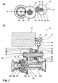
- Fig. 2 shows a first embodiment of a final drive 100 according to the invention, wherein partial figure a) represents a view in the axial direction, while part figure b) shows a sectional view along the section line BB in part figure a).
- the final drive 100 essentially comprises three main components, namely an electric machine 120, a three-stage transmission gear 140 and a differential 180.
- the electron machine 120 generates a torque that is applied to the output shaft 122 of the electric machine 120:
- the output shaft 122 is coupled to the input shaft 142 by means of a shaft / hub connection.
- the input shaft 142 together with its associated, rotatably mounted on her and in the illustrated embodiment integrally running respectivelysstirnrad 144, the first stage of the transmission gear 140.
- Das first Eisenstirnrad 146 is rotatably mounted in the illustrated embodiment about a rigidly connected to a housing, not shown bolt 148.
- a second Eisenstirnrad 150 which forms a one-piece wheel body together with the first spur gear 146 in the illustrated embodiment.
- an adaptation of the final drive according to the invention can be adapted to the specifications of certain motor vehicle models. The following elements, however, preferably remain the same across models.
- the third stage of the transmission gear 140 forms the actual switching stage in the illustrated embodiment.
- the second intermediate gear 150 of the intermediate meshes with a ratchet wheel 152, which is axially fixed and rotatably mounted in the unswitched state about a switching shaft 154.
- the switching shaft 154 is used in the illustrated embodiment at the same time as a drive shaft for driving the downstream differential 180.
- the switching gear 152 rotatably coupled to the switching shaft 154.
- the torque introduced via the two first stages of the transmission gear 140 is transmitted to the drive wheel 156, which is coupled in a rotationally fixed manner to the drive shaft 154 and is embodied in one piece in the illustrated embodiment.
- the drive wheel 156 meshes with the drive wheel 182 of the differential 180, wherein the drive wheel 182 rotatably connected to the differential carrier 184 is connected.
- the differential 180 is essentially a known bevel gear differential with two axle wheels 186a and 186b coupled via differential gears 188 which rotate about a pin 190 rigidly coupled to the differential carrier 184.
- the axle wheels 186a and 186b are directly connected to stub shafts 192a and 192b, which are coupleable in a conventional manner to the rear wheels of the motor vehicle, not shown.
- the switching device for the selective production and solution of a rotationally fixed connection between the ratchet wheel 152 and the shift shaft 154 is executed in the embodiment shown as a synchronization, as it is known in principle from manually operated transmissions.
- the synchronization comprises a sliding sleeve 158 which is rotatably mounted with the switching shaft 154 and axially displaceable on this.
- the sliding sleeve 158 has an internal toothing, which engages in the coupled state in an external toothing of a rotatably connected to the ratchet wheel 152 clutch body 160.
- a synchronizer 162 is arranged between the sliding sleeve 158 and the coupling body 160, which is limited relative to the sliding sleeve 158, in particular by half a tooth width, is rotatable.
- the synchronizing body 162 strikes a friction cone, so that it is offset by half the tooth width against the sliding sleeve 158 due to the frictional engagement. In this state, the synchronizer 162 prevents further advancement of the sliding sleeve 158 until this - and with it the switching shaft 154 - reaches the same rotational speed as the coupling body - and with it the ratchet wheel.
- the synchronizer body 162 is free of forces and allows a low wear and low noise engagement of the internal teeth of the sliding sleeve 158 in the outer toothing of the coupling body 160th
- the sliding sleeve 158 is biased by a coil spring 164 so that the switching gear 152 and the switching shaft 154 are decoupled without concern a switching force.
- Fig. 3 shows a sectional view through the used in the third gear stage of the transmission gear 140 coupling device, but also independent can be used by the final drive 100 discussed here and represents only one embodiment of a universally applicable coupling device.
- the components to be connected in the context of the coupling process are, on the one hand, the selector shaft 154 and, on the other hand, the selector wheel 152, which is rotatably and axially fixed on the selector shaft 154.
- the ratchet wheel 152 is from the upstream gear stage, from the in Fig. 3 only the meshing with the ratchet wheel 152 second idler 150 is shown in regions, driven.
- the indexing wheel 152 rotates freely about the switching shaft 154.
- the switching shaft 154 rotates with the ratchet wheel 152, so that the driving wheel 156 fixedly connected to the switching shaft 154 can drive the drive wheel 182 of the differential cage 180.
- the sliding sleeve 158 is axially displaced against the spring force, so that its internal toothing engages in the external toothing of the clutch wheel 152 rotatably connected to the coupling body 160.
- To minimize wear and switching noise is arranged between the sliding sleeve 158 and the coupling body 160 of the synchronizer body 162 which is rotatableêt.der the sliding sleeve 158 limited.
- the rotatability range of the synchronizer body 162 with respect to the sliding sleeve 158 is preferably about half a tooth width.
- the synchronizer body 162 prevents engagement of the teeth of the sliding sleeve 158 in the toothing of the coupling body 160 until the shift shaft 154 is accelerated by frictional engagement with the rotational speed of the switching wheel 152. At this time, the toothing of the synchronizer body 162 aligns with that of the sliding sleeve 158, so that the latter engage in the toothing of the synchronizer body 160 and can establish a rotationally fixed connection between the switching shaft 154 and the ratchet wheel 152.
- a mechanism for axial displacement of the sliding sleeve 158, a mechanism is provided which comprises a first ramp plate 167a and a second ramp plate 167b.
- the ramp disk 167b is in the illustrated embodiment, relative to a housing, not shown, neither rotatable nor axially movable.
- the ramp disc 167a is relative to the ramp disc 167b to a limited sector, preferably at least 90 ° rotatable and axially displaceable.
- Spacer balls 170 are disposed between the ramp discs 167a and 167b and run in guides 169a, 169b of the ramp discs 167a, 167b. These guides are as in Fig.
- the rotation of the rotatable ramp disk 167a is initiated by an electric motor 166, which has an in Fig. 3 unrecognizable spur gear with an in Fig. 3 likewise not recognizable toothing of the rotatable ramp disc 167a interacts.
- the rotatable ramp disk 167a is rotationally coupled by the sliding sleeve 158 via a thrust bearing 159.
- the ramp slope of the guide 169a of the rotatable ramp disk 167a is opposite to the intended direction of rotation of the switching wheel 152. This means that in case of blockage of the thrust bearing 159, i.
- the rotatable ramp disc 167a is unintentionally entrained by the rotation of the ratchet wheel 152, the distance between the ramp discs 167a, 167b is reduced. In other words, in this case, the coupling device is transferred to its release position and the switching shaft 154 is decoupled from the indexing wheel 152.
- Fig. 4 shows a second embodiment of a final drive 100 according to the invention, wherein the same reference numerals as in Fig. 2 designate the same or analogous elements.
- the description of Fig. 4 only those features are discussed in detail, in which the embodiment of Fig. 4 from that of Fig. 2 different. Incidentally, the detailed description of Fig. 2 directed.
- the actuator is designed as a tangentially engaging claw 168 '.
- the claw 168 ' engages in an annular groove 172 of the sliding sleeve 158.
- the sliding sleeve 158 on the compared to the embodiment of Fig. 2 engages other side of the switching wheel 152.
- Another constructive difference is the displacement of the springs 164 to the outside of the sliding sleeve 158.
- the spring force acts in this embodiment on the jaw 168 'and thus only indirectly on the sliding sleeve 158.
- the displacement to the outside simplifies the internal structure of the synchronization.
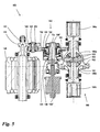
- Fig. 5 shows a third embodiment of the axle drive 100 according to the invention, again like reference numerals the same or analogous elements as in the Figures 2 and 4 describe. For the sake of clarity, reference is also made here to the preceding description with regard to the essentially identical elements. It should only the specifics of the embodiment of Fig. 5 in comparison to the embodiments of Figures 2 and 4 be discussed in more detail.
- the input shaft of the transmission gear 140 and the output shaft of the electric machine 120 are integrally formed. This means a complete integration of the electric machine 120 in the final drive 100.
- the combined shaft carries in Fig. 5 the reference symbol 143.
- the actuator 166 and 166 'in the embodiments according to Figures 2 and 4 is arranged parallel to the switching shaft 154, it is in the embodiment of Fig. 5 arranged in extension of the hollow running switching shafts 154.
- the actuating element 168 "has a tappet-like design and protrudes into the hollow switching shaft 154.
- the tappet 168" is designed in two parts, the tappet head being mounted rotatably against the tappet neck and the selector shaft 154 passing outwards in order to engage the sliding sleeve 158 there.
- the head of the plunger 168 "rotates with the switching shaft 154, while its neck is non-rotatably coupled to the housing-fixed actuating device 166.
- the embodiment differs from Fig. 5 in the design of the differential 180.
- the storage of transmission gear 140 has not been discussed in greater detail. However, this is preferably fixed-lot storage, i. not as tapered roller bearing.
- the differential 180 may be formed substantially like a conventional differential. However, embodiments are particularly advantageous in which the Achsantriebsrad 182 is welded to the differential carrier 184. In this case, the weld can be designed as an axial seam with relief notch in the differential housing.
- the centering of the axle drive wheel 182 preferably takes place via a radial press fit with a large overlap length. Due to the low axle torque is also an interference fit with additional bonding or cutting teeth on the final drive 182 conceivable for the connection of the final drive 182 and the differential housing.
- the axle drive according to the invention can be used with a start / stop function in the context of a hybrid system for recuperation and for electric drive, wherein a run as a low-voltage power electronics can be used.
- a generator with a flying operating voltage of up to 60 volts (low voltage) is used.
- the generator supplies the electrical power directly to the capacitive energy storage, so-called “supercaps”.
- the generator With completely discharged "supercaps" and requirement of all-wheel functionality, the generator delivers the greatest possible power over the supercaps to the electric machine of the final drive according to the invention.
- the all-wheel function can thus always be used (even with unloaded supercaps).
- no additional backup battery for the hybrid functionality is provided.
- the vehicle electrical system is supplied with power via a separate "lead-acid battery”.
- the battery is charged via a DC / DC converter, which is supplied with voltage by the supercaps.
- the starter is preferably pre-loaded, ie at engine standstill, the starter is already meshed in the starter ring gear. The starter can thus begin without further delay upon request rotate.
- the starter ring gear is strengthened for the increased load change requirements.
- other starter concepts such as enhanced starter, assisted direct start, belt starter or crankshaft starter are conceivable.
- the air conditioning compressor is preferably electrically powered for high comfort for the best possible utilization of the recuperation energy. With higher evaluation of the cost aspects, a mechanical air conditioning compressor is also possible.
- the start / stop functionality can in principle be combined with any engine / gearbox variant. Preferably, however, automatic and automated transmissions are used. The changes to the front end are minor and can be incorporated into the module strategy.
- the electric rear axle can be used in the space of rear axle drives.
- the rear axle is preferably 100% COP of conventional four-wheel vehicles of the affected platform.
- the supercaps are placed together with the power electronics in the rear, preferably in the spare wheel well of the vehicle.
- the cooling of these elements is preferably carried out by convection.
- ventilation ducts are introduced, for example, into the "spare wheel well", which is preferably made of plastic.
- other ventilation ducts are to be introduced into the body, which then, however, arise body styles. If necessary, they can be force-ventilated by means of a thermostat-actuated fan. An additional cooling through support by heat exchangers is not required.
- the conventional "lead-acid battery” and the DC / DC converter are preferably also placed in the rear carriage. This arrangement enables shortest cable lengths of both control and power cables, and the simplest possible integration of the production of hybrid vehicles in the production processes and systems preferably of all-wheel drive vehicles.
- the boost, electric drive and traction-assisted four-wheel functions are automatically executed by driving condition detection or can be activated as a direct driver request (four-wheel drive).
- the functions of electric driving and boosting are possible only over short distances due to the low storage capacity of the supercaps.
- An "electric" brake pedal is preferably not provided. That is, the braking effect will vary depending on the Rekuperationsanteil (degree of filling of the supercaps) at the same brake pedal position.
- a recuperation is at speeds up to about 120 km / h allows. Above this speed or when requesting the "Brake Assist" (ABS, ESP, EDS), the electric machine is disconnected from the wheels. At the vehicle speed of about 120 km / h, the electric machine is to rotate at speeds of up to 15,000 rpm. Higher speeds are preferably avoided in order not to have to meet unreasonably high demands on the thermal stability of the electric machine, gear noise, bearing life, balancing accuracy, etc.
- the electric machine should have a power of about 9,000 watts. In this case, a starting torque of 450 Nm on average at the rear axle should be achieved. Depending on the state of charge of the supercaps, this starting torque can vary. The maximum torque for fully charged supercaps and a voltage of 60 volts should be 900 Nm. The starting torque should be applied up to speeds of at least 10 km / h. Electric driving and four-wheel drive should be possible up to about 30 km / h.
Abstract
Description
Die Erfindung betrifft einen Achsantrieb für ein Kraftfahrzeug, umfassend
- eine Elektromaschine zur Erzeugung eines Momentes,
- ein Differential zur Verteilung eines eingeleiteten Momentes an mit dem Differential koppelbare Räder,
- ein als ein Stirnradgetriebe ausgebildetes Übertragungsgetriebe mit mehreren jeweils eine Welle und wenigstens ein auf der Welle angeordnetes Stirnrad umfassenden Stufen, zur Übertragung des von der Elektromaschine erzeugten Momentes auf das Differential sowie
- eine Schalteinrichtung zur wahlweisen An- und Abschaltung der Momentenübertragung von der Elektromaschine auf die Räder,
mit den Merkmalen des Oberbegriffs des Anspruch 1.The invention relates to a final drive for a motor vehicle, comprising
- an electric machine for generating a moment,
- a differential for distributing an input torque to wheels engageable with the differential,
- a transmission gear formed as a spur gear with a plurality of respective one shaft and at least one arranged on the shaft spur gear stages, for transmitting the torque generated by the electric machine to the differential and
- a switching device for selectively switching on and off the transmission of torque from the electric machine to the wheels,
with the features of the preamble of claim 1.
Die Erfindung betrifft weiter einen Achsantrieb mit einer elektrisch betätigten Kupplungseinrichtung zum wahlweisen Herstellen und Lösen einer drehfesten Verbindung zwischen einer Schaltwelle und einem koaxial auf der Schaltwelle angeordneten Schaltkörper durch elektrische Verstellung eines Koppelgliedes, das zwischen einem Lösezustand, in dem die Schaltwelle und der Schaltkörper gegeneinander verdrehbar sind, und einem Koppelzustand, in dem das Koppelglied sowohl die Schaltwelle als auch das Schaltelement drehfest kontaktiert, verstellbar ist.The invention further relates to a final drive with an electrically actuated clutch device for selectively establishing and releasing a rotationally fixed connection between a shift shaft and a coaxially arranged on the shift shaft switching body by electrical adjustment of a coupling member which rotates between a release state in which the shift shaft and the switch body against each other are, and a coupling state in which the coupling member contacted both the switching shaft and the switching element rotationally fixed, is adjustable.
Ein gattungsgemäßer Achsantrieb ist bekannt aus der
Nachteilig bei dieser bekannten Vorrichtung ist zum einen ihr komplizierter Aufbau, der sich insbesondere aus der Realisierung verschiedener Übersetzungsverhältnisse herleitet. Bei Verwendung moderner Elektromaschinen und insbesondere bei Einsatz des Achsantriebs als Sekundärantrieb, der lediglich bei geringen Geschwindigkeiten des Kraftfahrzeugs zum Einsatz kommt, ist eine solche Schaltmöglichkeit nicht erforderlich. Ein weiterer Nachteil der bekannten Vorrichtung besteht darin, dass auch bei abgeschalteter Momentenübertragung zwischen der Elektromaschine und den Rädern der ein hohes Trägheitsmoment aufweisende Differentialkorb ständig weiter von der Elektromaschine angetrieben wird, was zu erhöhtem Energieverbrauch und unerwünschter Geräuschentwicklung führt.A disadvantage of this known device is on the one hand its complicated structure, which is derived in particular from the realization of different ratios. When using modern electric machines and in particular when using the final drive as a secondary drive, which is used only at low speeds of the motor vehicle, such a switching option is not required. Another disadvantage of the known device is that even when switched off torque transmission between the electric machine and the wheels of a high moment of inertia differential carrier is constantly driven by the electric machine, which leads to increased energy consumption and unwanted noise.
Im Dokument
Im Dokument
Es ist die Aufgabe der vorliegenden Erfindung, einen gattungsgemäßen Achsantrieb einfacher, energiesparender und geräuschärmer auszubilden.It is the object of the present invention to form a generic axle drive simpler, energy-saving and quieter.
Diese Aufgabe wird durch einen Achsantrieb mit den Merkmalen des Anspruchs 1 gelöst.This object is achieved by a final drive with the features of claim 1.
Ein wesentlicher Gedanke der vorliegenden Erfindung ist es, die Schalteinrichtung aus dem Differential in das vorgelagerte Übertragungsgetriebe zu verlegen. Auf diese Weise kann als Differential jedes herkömmliche Differential verwendet werden, was insbesondere bei der Umrüstung von herkömmlichen Kraftfahrzeugen auf Hybrid-Kraftfahrzeuge ein erhebliches Einsparpotenzial bietet, da keine wesentlichen Änderungen der in herkömmlichen Kraftfahrzeugen eingesetzten Differentiale vorgenommen werden müssen.An essential idea of the present invention is to move the switching device from the differential into the upstream transmission transmission. In this way, as a differential, any conventional differential can be used, which offers a considerable potential for savings, especially in the conversion of conventional motor vehicles to hybrid vehicles, since no significant changes to the differentials used in conventional motor vehicles must be made.
Die erfindungsgemäß vorgesehene Art der Schalteinrichtung, nämlich als wahlweise Kopplung zwischen dem Schaltrad und der ihm zugeordneten Schaltwelle, erlaubt zudem eine sehr kompakte Bauweise, was im Hinblick auf den benötigten Bauraum vorteilhaft ist. Insbesondere lässt sich auf diese Weise eine parallele Anordnung der Elektromaschine, der Wellen des Übertragungsgetriebes und des Differentialkorbes realisieren, so dass ein hohes Maß an Integration erreicht werden kann.The inventively provided type of switching device, namely as an optional coupling between the ratchet wheel and its associated shift shaft also allows a very compact design, which is advantageous in terms of the required space. In particular, a parallel arrangement of the electric machine, the shafts of the transmission gear and the differential cage can be realized in this way, so that a high degree of integration can be achieved.
Bei einer bevorzugten Ausführungsform der Erfindung ist das Schaltrad auf der Ausgangswelle des Übertragungsgetriebes angeordnet. Dies bedeutet, dass die Welle der letzten Stufe des Übertragungsgetriebes als Schaltwelle wirkt. Bevorzugt ist ein dreistufiges Übertragungsgetriebe, insbesondere mit starrer Übersetzung, vorgesehen, wobei die dritte Stufe in einem Zwischenraum zwischen der Elektromaschine und dem Differential angeordnet ist. Die erste und zweite Stufe des Übertragungsgetriebes können eingesetzt werden, um die Baubreite der Elektromaschine zu überbrücken und um einen Teil der vorzugsweise hohen Übersetzung, wie etwa 1:14, zu realisieren. Dieser Teil des Getriebes kann variabel gestaltet sein, so dass durch Wahl der Zahnzahlen der beteiligten Stirnräder eine Anpassung an das jeweilige Kraftfahrzeugmodell vorgenommen werden kann. Schaltstufe des Übertragungsgetriebes und das Differential bleiben hingegen vorzugsweise modellübergreifend gleich. Die Angleichung des Bauraums der beiden ersten Stufen des Übertragungsgetriebes an die Baubreite der Elektromaschine ist insbesondere in vollintegrierten Fällen günstig in denen die Abtriebswelle der Elektromaschine einstückig mit der Eingangswelle des Übertragungsgetriebes ausgebildet ist. Andererseits kann die Verbindung zwischen der Abtriebswelle der Elektromaschine und der Eingangswelle des Übertragungsgetriebes auch durch eine direkte Kopplung erfolgen, z. B. durch eine Welle/Nabe-Verbindung.In a preferred embodiment of the invention, the ratchet wheel is arranged on the output shaft of the transmission gear. This means that the shaft of the last stage of the transmission gear acts as a switching shaft. Preferably, a three-stage transmission gear, in particular with a rigid translation, provided, wherein the third stage is arranged in a space between the electric machine and the differential. The first and second stages of the transfer gear can be used to bridge the width of the electric machine and to realize part of the preferably high gear ratio, such as 1:14. This part of the transmission can be designed variable so that an adaptation to the respective motor vehicle model can be made by selecting the numbers of teeth of the involved spur gears. Switching stage of the transmission gear and the differential, however, preferably remain the same across models. The approximation of the space of the first two stages of the transmission gear to the width of the electric machine is particularly favorable in fully integrated cases in which the output shaft of the electric machine is formed integrally with the input shaft of the transmission gear. On the other hand, the connection between the output shaft of the electric machine and the input shaft of the transmission gear can also be effected by a direct coupling, for. B. by a shaft / hub connection.
Als Schalteinrichtung zur wählbaren Kopplung zwischen dem Schaltrad und der zugeordneten Schaltwelle haben sich insbesondere zwei alternative Varianten bewährt. In einfachen Fällen, kann die Schalteinrichtung als Klauenkupplung ausgebildet sein, die eine axial auf der Schaltwelle bewegbare und drehfest mit ihr verbundene Schiebemuffe mit einer Verzahnung aufweist, die im eingekuppelten Zustand in eine Verzahnung eines mit dem Schaltrad drehfest verbundenen Kupplungskörper eingreift. Derartige Klauenkupplungen sind von ihrem Prinzip her aus manuellen betätigten Getrieben bekannt.As a switching device for selectable coupling between the ratchet wheel and the associated shift shaft, in particular two alternative variants have been proven. In simple cases, the switching device may be formed as a dog clutch having an axial on the Switching shaft movable and non-rotatably connected with her sliding sleeve having a toothing, which engages in the engaged state in a toothing of a non-rotatably connected to the ratchet coupling body. Such jaw clutches are known in principle from manual actuated transmissions.
Bei einer anderen, bevorzugten Ausführungsform der Erfindung ist die Schalteinrichtung als Synchronisierung ausgebildet, die eine axial auf der Schaltwelle bewegbare und drehfest mit ihr verbundene Schiebemuffe mit einer Verzahnung aufweist, die im eingekuppelten Zustand in eine Verzahnung eines mit dem Schaltrad drehfest verbundenen Kupplungskörpers eingreift, wobei ein gegenüber der Schiebemuffe beschränkt drehbeweglicher Synchronkörper das Eingreifen erst gestattet, wenn keine Relativbewegung zwischen Schaltrad und Schaltwelle vorliegt. Derartige Synchronisierungen sind ebenfalls grundsätzlich aus manuell betätigten Schaltgetrieben bekannt. Der Kupplungskörper ist dabei vorzugsweise an das Schaltrad angeschweißt oder angeschmiedet. Im eingeschalteten Zustand gelangt die Leistung über den Kupplungskörper, die Schiebemuffe und den Synchronkörper auf die Schaltwelle. Die Schiebemuffe kann dabei je nach Betätigungseinrichtung unterschiedlich ausgeführt sein. Vorzugsweise ist die Muffe ohne Nut oder Steg ausgeführt, sondern besitzt axiale Anlaufflächen oder Lagersitze für Axiallager, über die die Schaltkraft aufgebracht wird. Alternativ sind auch Schiebemuffen mit Nuten oder Stegen für den Eingriff von Schaltgabeln möglich.In another preferred embodiment of the invention, the switching device is designed as a synchronization, which has an axially movable on the shift shaft and rotatably connected with her sliding sleeve with a toothing, which engages in the engaged state in a toothing of a non-rotatably connected to the ratchet clutch body, wherein a relative to the sliding sleeve limited rotatable synchronizer body only allows the intervention when there is no relative movement between the ratchet and shift shaft. Such synchronizations are also basically known from manually operated manual transmissions. The coupling body is preferably welded or forged to the ratchet wheel. When switched on, the power reaches the selector shaft via the coupling body, the sliding sleeve and the synchronizer body. The sliding sleeve can be designed differently depending on the operating device. Preferably, the sleeve is designed without a groove or web, but has axial thrust surfaces or bearing seats for thrust bearings, via which the switching force is applied. Alternatively, sliding sleeves with grooves or webs for the engagement of shift forks are possible.
Bei der bevorzugten Ausführungsform der Schalteinrichtung als Synchronisierung ist vorzugsweise vorgesehen, dass bei mindestens einem der Schaltkörper, d.h. Kupplungskörper oder Schiebemuffe, vorzugsweise jedoch bei beiden, die Hinterlegung auf ein Minimum reduziert wird bzw. entfällt, d.h. Hinterlegungswinkel etwa 0°. Die Synchronisierung wird vorzugsweise für hohe Synchronisierungsleistungen ausgelegt, die bei Regelstörungen der Elektromaschine oder durch hochdynamische Änderungen der Raddrehzahlen durch Fahrbahneinfluss auftreten können. Damit die maximalen Synchronisierungsleistungen bei kleinen Betatigungskräften und kurzen Schaltzeiten erreicht werden, wird vorzugsweise eine Mehrkonus-Synchronisierung insbesondere mit zwei oder drei Konen verwendet.In the preferred embodiment of the switching device as a synchronization is preferably provided that in at least one of the switching body, i. Coupling body or sliding sleeve, but preferably in both, the deposit is reduced to a minimum or is omitted, i. Deposit angle about 0 °. The synchronization is preferably designed for high synchronization performance, which can occur in the case of disturbances in the control of the electric machine or by highly dynamic changes in the wheel speeds due to the influence of the road surface. So that the maximum synchronization powers are achieved with small actuating forces and short switching times, preferably a multi-cone synchronization is used, in particular with two or three cones.
Die Rückstellung der Schiebemuffe erfolgt entweder direkt oder indirekt, insbesondere über Federn. Die Federn sind vorzugsweise so dimensioniert, dass eine Rückstellkraft von 20-400 Newton realisiert wird, um eine schnelle Rückstellung, d.h. eine rasche Entkopplung zwischen Elektromaschine und Rädern vorzugsweise innerhalb von 0,1-0,25 Sekunden zu realisieren.The provision of the sliding sleeve takes place either directly or indirectly, in particular via springs. The springs are preferably sized to provide a restoring force of 20-400 Newtons to provide a quick return, i. to realize a rapid decoupling between the electric machine and wheels preferably within 0.1-0.25 seconds.
Bevorzugt ist die Schiebemuffe derart federvorgespannt, dass das Schaltrad und die Schaltwelle im unbetätigten Zustand der Schiebemuffe entkoppelt sind. Mit anderen Worten ist vorzugsweise eine "Normaly-Open"-Konfiguration realisiert. Alternativ kann auch eine aktive Rückstellung vorgesehen sein. Die Einstellung der Schiebemuffe kann auf jede motorische, dem Fachmann bekannte Weise erfolgen. Insbesondere kann eine Betätigungseinrichtung, die der Einstellung der Schiebemuffe dient, elektromotorisch, elektromagnetisch durch Hubmagnet, pneumatisch, hydraulisch oder auf andere Weise arbeiten.Preferably, the sliding sleeve is spring biased such that the ratchet and the shift shaft are decoupled in the unactuated state of the sliding sleeve. In other words, a "normaly-open" configuration is preferably realized. Alternatively, an active Provision be provided. The adjustment of the sliding sleeve can be done in any motor, known in the art. In particular, an actuating device which serves to adjust the sliding sleeve, electric motor, electromagnetically by solenoid, pneumatically, hydraulically or otherwise work.
Der Angriff der Betätigungseinrichtung an der Schiebemuffe kann auf unterschiedliche Weise gestaltet sein. Besonders vorteilhaft ist es, wenn die Schiebemuffe mittels eines in der hohl ausgeführten Schaltwelle angeordneten Betätigungselementes der Betätigungseinrichtung bewegbar ist. Diese Variante, bei der beispielsweise ein Hubmagnet in Verlängerung der Schaltwelle angebracht und mit einem Stößel in die hohle Schaltwelle hineinragen kann, ist im Hinblick auf die Bauraumanforderungen besonders vorteilhaft. Mechanisch einfacher zu realisieren sind jedoch Ausführungsformen, bei denen die Betätigungseinrichtung benachbart zu der Schaltwelle angeordnet ist und die Schiebemuffe über ein Betätigungselement mit einer axial gerichteten Kraft beaufschlagbar und somit axial bewegbar ist. Das Betätigungselement kann beispielsweise tangential in Form einer Schaltgabel außen an der Schiebemuffe ansetzen. Alternativ kann das Betätigungselement auch an einer quer zur Axialrichtung liegenden Fläche, beispielsweise einer Bodenfläche der Schiebemuffe, angreifen.The attack of the actuator on the sliding sleeve can be designed in different ways. It is particularly advantageous if the sliding sleeve can be moved by means of an actuating element of the actuating device arranged in the hollow switching shaft. This variant, in which, for example, a solenoid mounted in extension of the shift shaft and can protrude with a plunger in the hollow shaft, is particularly advantageous in terms of space requirements. However, embodiments in which the actuating device is arranged adjacent to the switching shaft and the sliding sleeve can be acted upon by an actuating element with an axially directed force and thus can be moved axially are mechanically simpler to implement. The actuator may, for example tangentially in the form of a shift fork attach externally to the sliding sleeve. Alternatively, the actuating element can also act on a surface lying transversely to the axial direction, for example a bottom surface of the sliding sleeve.
Eine besonders vorteilhafte Ausführungsform der letztgenannten Alternative wird durch eine Weiterbildung der eingangs genannten Kupplungseinrichtung realisiert, die allerdings auch unabhängig von dem erfindungsgemäßen Achsantrieb eingesetzt werden kann. Die eingangs erwähnte Kupplungseinrichtung ist bekannt aus der
Nachteilig bei der bekannten Vorrichtung ist zum einen die notwendige große Materialhärte, die erforderlich ist, um verschleißarm die hohen Klemmkräfte zu tolerieren. Ein weiterer Nachteil besteht darin, dass der Schaltmoment nicht präzise bestimmt werden kann, da zwischen der Lösestellung und der Kopplungsstellung ein Spielwinkel von mindestens 30° liegt. Schließlich ist es ein Nachteil der bekannten Vorrichtung, dass sowohl der Übergang in die Koppelstellung als auch von der Koppelstellung in die Lösestellung eine aktive Betätigung erfordert, so dass insbesondere bei Ausfall der elektromagnetischen Betätigungsvorrichtung im Kopplungszustand keine automatische Entkopplung erfolgt.A disadvantage of the known device, on the one hand, the necessary large material hardness, which is required to wear the high clamping forces wear. Another disadvantage is that the switching torque can not be precisely determined because between the release position and the coupling position is a play angle of at least 30 °. Finally, it is a disadvantage of the known device that both the transition to the coupling position and from the coupling position into the release position requires active actuation, so that in particular in case of failure of the electromagnetic actuator in the coupling state no automatic decoupling takes place.
Einer Weiterbildung liegt die Aufgabe zugrunde, eine alternative Kupplungseinrichtung zur Verfügung zu stellen, die ein schnelleres und präziseres Schalten ermöglicht und in einer bevorzugten Ausführungsform einen automatischen Übergang in die Lösestellung bei Ausfall der Betätigungseinrichtung sicherstellt. Eine derartig verbesserte Kupplungsvorrichtung wäre insbesondere zur Betätigung der Schalteinrichtung des erfindungsgemäßen Achsantriebs sehr gut geeignet.A further object of the invention is to provide an alternative coupling device which enables a faster and more precise shifting and, in a preferred embodiment, ensures an automatic transition to the release position in the event of failure of the actuating device. Such an improved clutch device would be very well suited in particular for actuating the shifting device of the axle drive according to the invention.
Die Aufgabe wird in Verbindung mit den Merkmalen des Oberbegriffs von Anspruch 11 gelöst durch ein Paar koaxial zu der Schaltwelle angeordneter Rampenscheiben mit einander gegenüberliegenden, korrespondierenden und sich ring- oder teilringförmig erstreckenden Führungen von denen wenigstens eine eine sich über ihre Länge rampenartig ändernde Tiefe aufweist, zur Führung von Abstandskugeln, wobei eine der Rampenscheiben axial gehäusefest und die andere der Rampenscheiben axial verschiebbar ist und eine der Rampenscheiben relativ zu der anderen mittels eines Elektromotors über einen beschränkten Sektor derart drehbar ist, dass mit der Drehung ein durch Wechselwirkung der Abstandskugeln mit ihren Führungen bestimmter Abstand der Rampenscheiben einstellbar und das mit der axial verschiebbaren Rampenscheibe in Wirkkontakt stehende und als Schiebemuffe ausgebildete Koppelglied zwischen seiner Koppelstellung und seiner Lösestellung axial verschoben werden kann.The object is achieved in conjunction with the features of the preamble of claim 11 by a pair of coaxial with the switching shaft arranged ramp discs with opposing, corresponding and ring or partially annularly extending guides of which at least one has a ramp-like depth over its length, for guiding spacer balls, wherein one of the ramp discs axially fixed to the housing and the other of the ramp discs is axially displaceable and one of the ramp discs relative to the other by means of an electric motor over a limited sector is rotatable such that with the rotation of an interaction of the spacer balls with their guides certain distance of the ramp discs adjustable and standing in operative contact with the axially displaceable ramp disc and formed as a sliding sleeve coupling member between its coupling position and its release position can be moved axially.
Die. Weiterbildung basiert auf einer völligen Umgestaltung der bekannten Kupplungseinrichtung. Als Betätigungselement wird ein Paar koaxial zu der Schaltwelle angeordneter Rampenscheiben eingesetzt. Zwischen den Rampenscheiben werden Abstandskugeln geführt, die in Nuten der Rampenscheiben gelagert sind. Die Nuten erstrecken sich konzentrisch um den Scheibenmittelpunkt, wobei jede Nut vorzugsweise aus drei Teilabschnitten, die sich jeweils über etwa 120° erstrecken, aufgebaut ist. Auch ist es möglich, dass die Nuten nicht durchgehend realisiert sind, sondern in mehreren, strikt voneinander getrennten Teilabschnitten. Die Tiefe der Nuten ändert sich mit der Länge ihrer Erstreckung. Dies bedeutet, dass bei einer relativen Verdrehung der Rampenscheiben zueinander die Abstandskugeln tiefer oder weniger tief in den Nuten versenkt sind. Dies führt dazu, dass im Fall, dass die Rampenscheiben derart zueinander kraftbeaufschlagt sind, dass beide Rampenscheiben stets Kontakt zu den Abstandskugeln haben, sich der Abstand der Rampenscheiben zueinander mit ihrer relativen Drehung ändert. Dabei ist vorgesehen, dass eine der Rampenscheiben axial festgelegt ist und die zweite Rampenscheibe axial verschieblich ist, wobei eine der Rampenscheiben drehbar ist. Dies ist vorzugsweise diejenige Rampenscheibe, die auch axial verschiebbar ist. Wird nun die drehbare Rampenscheibe mit Hilfe des Elektromotors über einen beschränkten Sektor, der vorzugsweise mit dem von jedem Teilabschnitt der Führungsnuten überspannten Sektor korreliert ist, verdreht, kann der Abstand der Rampenscheiben zueinander sehr genau eingestellt werden.The. Training is based on a complete transformation of the known coupling device. As an actuating element, a pair of coaxial with the switching shaft arranged ramp discs is used. Between the ramp discs spacer balls are guided, which are mounted in grooves of the ramp discs. The grooves extend concentrically around the disk center, wherein each groove is preferably constructed of three sections, each extending over about 120 °. It is also possible that the grooves are not implemented continuously, but in several, strictly separate sections. The depth of the grooves changes with the length of their extension. This means that with a relative rotation of the ramp discs to each other, the spacer balls are sunk deeper or less deep in the grooves. As a result, in the event that the ramp discs are subjected to force to one another in such a way that both ramp discs always have contact with the spacer balls, the distance of the ramp discs from each other changes with their relative rotation. It is provided that one of the ramp discs is axially fixed and the second ramp disc is axially displaceable, wherein one of the ramp discs is rotatable. This is preferably that ramp disc which is also axially displaceable. Now, if the rotatable ramp disc with the aid of the electric motor over a limited sector, which is preferably correlated with the sector spanned by each section of the guide grooves twisted, the distance between the ramp discs can be set very accurately to each other.
Auf diese Weise wird ein auf der Schaltwelle axial bewegliches Betätigungselement geschaffen, über welches eine Schiebemuffe axial bewegt werden kann, die dann in einer im Grunde bekannten Weise eine formschlüssige Verbindung zwischen der Schaltwelle und dem vorzugsweise als Schaltrad ausgeführten Schaltkörper herstellen kann. Vorzugsweise wird eine Anordnung gewählt, bei der der Koppelzustand zwischen Schaltwelle und Schaltrad bei maximalem Abstand der Rampenscheiben zueinander realisiert ist und umgekehrt der Lösezustand zwischen Schaltwelle und Schaltrad bei minimalem Abstand der Rampenscheiben realisiert ist.In this way, an axially movable on the shift shaft actuating element is provided, via which a sliding sleeve can be moved axially, which can then produce in a basically known manner a positive connection between the switching shaft and preferably designed as a switching wheel switching body. Preferably, an arrangement is selected in which the coupling state between the switching shaft and the switching wheel is realized with maximum spacing of the ramp discs to each other and vice versa, the release state between the switching shaft and ratchet is realized with minimal spacing of the ramp discs.
Die Betätigung der Axialverschiebung der Schiebemuffe erfolgt vorzugsweise, indem ein von dem Elektromotor betätigtes oder mit diesem gekoppeltes Stirnrad mit einer Verzahnung der drehbaren Rampenscheibe kämmt. Im Fall, dass die drehbare Rampenscheibe auch zugleich die axial verschiebliche ist, wird die Höhe des Stirnrades günstigerweise so groß gewählt, dass es in jedem Abstandszustand der Rampenscheiben zueinander noch mit der Verzahnung der drehbaren und axial verschieblichen Rampenscheibe kämmt.The actuation of the axial displacement of the sliding sleeve is preferably carried out by one of the electric motor actuated or coupled thereto spur gear meshes with a toothing of the rotatable ramp disc. In the event that the rotatable ramp disc is at the same time also the axially displaceable, the height of the spur gear is favorably chosen so large that it meshes with each other in each distance state of the ramp discs with the teeth of the rotatable and axially displaceable ramp disc.
Um eine sehr präzise Abstandseinstellung der Rampenscheiben zueinander zu erreichen, ist vorteilhafterweise vorgesehen, dass der Sektor, in dem die drehbare Rampenscheibe drehbar ist, wenigstens 90° beträgt. Wie erwähnt, bestehen die Führungsnuten vorzugsweise aus drei Teilabschnitten von jeweils etwa 120°. Diesen maximal möglichen Einstellungsbereich gilt es möglichst umfassend zu nutzen. Weiter kann die Einstellungspräzision des Abstandes der Rampenscheiben durch eine geeignete Übersetzung zwischen dem Elektromotor und der drehbaren Rampenscheibe erreicht werden.In order to achieve a very precise distance adjustment of the ramp discs to each other, it is advantageously provided that the sector in which the rotatable ramp disc is rotatable, at least 90 °. As mentioned, the guide grooves preferably consist of three sections of approximately 120 ° each. It is important to use this maximum possible setting range as comprehensively as possible. Further, the adjustment precision of the distance of the Ramp discs can be achieved by a suitable translation between the electric motor and the rotatable ramp disc.
Die Wechselwirkung des als Schiebemuffe ausgebildeten Koppelgliedes kann auf unterschiedliche Weise umgesetzt werden. Bei einer besonders günstigen Ausführungsform ist vorgesehen, dass die Schiebemuffe über einen Synchronkörper eine formschlüssige Verbindung zwischen der Schaltwelle und dem Schaltkörper, d.h. insbesondere dem Schaltrad, erzeugt. Dies ist vom Prinzip her von Synchronisierungen manuell betätigter Getriebe bekannt.The interaction of the coupling member designed as a sliding sleeve can be implemented in different ways. In a particularly favorable embodiment, it is provided that the sliding sleeve via a synchronizer body a positive connection between the switching shaft and the switch body, i. in particular the ratchet generated. This is known in principle from synchronizing manually operated transmissions.
Alternativ kann bei einer konstruktiv einfacheren Variante die Schiebemuffe auch nach Art einer Klauenkupplung direkt die formschlüssige Verbindung zwischen Schaltwelle und Schaltkörper, d.h. insbesondere Schaltrad erzeugen.Alternatively, in a structurally simpler variant, the sliding sleeve also directly in the manner of a dog clutch directly the positive connection between the switching shaft and switch body, i. in particular generate ratchet wheel.
Wie oben bereits erwähnt, ist es wünschenswert, wenn die Kupplungseinrichtung im Fall einer Störung des Elektromotors selbsttätig in die Lösestellung übergeht. Dies wird vorzugsweise dadurch erreicht, dass die Schiebemuffe bzw. die axial bewegliche Rampenscheibe in Richtung eines minimalen Abstandes zwischen den Rampenscheiben federvorgespannt ist. Unterstützend kann in besonders vorteilhafter Weise vorgesehen sein, dass die zur Abstandssteigerung der Rampenscheiben erforderliche Drehung der Drehrichtung des Schaltkörpers im Koppelzustand entgegengerichtet ist. Es ist für den Fachmann offensichtlich, dass irgendwo im Kopplungsstrang zwischen der axial beweglichen Rampenscheibe, die höchstens um den von dem Elektromotor angesteuerten Sektor drehbar ist, und dem im Koppelzustand zusammen mit der Schaltwelle umlaufenden Schaltrad eine Drehentkopplung vorgesehen sein muss. Diese ist vorzugsweise als ein Axialnadellager an der Schnittstelle zwischen der Rampenscheibe und der Schiebemuffe ausgebildet. Im Fall einer Blockade dieser Entkopplungsstelle, d.h. im Fall, dass die Rampenscheibe von der Drehung des Schaltrades mitgerissen wird, ist vorzugsweise vorgesehen, dass sich durch diese Drehung der Abstand zwischen den Rampenscheiben nicht weiter vergrößert, sondern vielmehr verkleinert, d.h. das automatisch ein Übergang in den Lösezustand initiiert wird.As already mentioned above, it is desirable if the coupling device automatically transitions into the release position in the event of a fault in the electric motor. This is preferably achieved in that the sliding sleeve or the axially movable ramp disc is spring-biased in the direction of a minimum distance between the ramp discs. Supporting can be provided in a particularly advantageous manner that the required to increase the distance of the ramp discs rotation of the direction of rotation of the switch body is opposite in the coupling state. It is obvious to a person skilled in the art that a torsional decoupling must be provided somewhere in the coupling line between the axially movable ramp disc, which is rotatable at most about the sector driven by the electric motor, and the switching wheel which rotates in the coupling state together with the switching shaft. This is preferably designed as an axial needle bearing at the interface between the ramp disc and the sliding sleeve. In the case of a blockade of this decoupling point, i. in the event that the ramp disc is entrained by the rotation of the ratchet wheel, it is preferably provided that, due to this rotation, the distance between the ramp discs is not further increased, but rather reduced, i.e. reduced in size. automatically initiating a transition to the release state.
Aus dem Vorangehenden wird dem Fachmann klar, dass die Kupplungseinrichtung in ihrer bevorzugten Ausführungsform aktiv im Koppelzustand gehalten werden muss. Dies wird günstigerweise dadurch erreicht, dass ein Sensor vorgesehen ist, der das Erreichen des Koppelzustandes erkennt und an ein Steuergerät meldet. Das Steuergerät betätigt dann eine elektrische Bremse des Elektromotors, um den Koppelzustand auch entgegen der Reibungskraft der vorzugsweise als Axialnadellager ausgebildeten Drehentkopplung aufrechtzuerhalten. Es hat sich gezeigt, dass ein Elektromotor mit einem maximalen Motornennmoment von weniger als 1,5 Nm typischerweise zur Betätigung der erfindungsgemäßen Kupplungseinrichtung ausreicht und eine elektrische Bremse des Motors mit einem Bremsnennmoment von nicht mehr als 0,7 Nm typischerweise ausreicht, um den Koppelzustand beizubehalten. Im Fall eines Ausfalls des Elektromotors und somit auch seiner elektrischen Bremse, wird die erfindungsgemäße Kupplungsvorrichtung einerseits aufgrund der Federvorspannung und andererseits auch mit Hilfe der Reibung an der Entkopplungsstelle automatisch in den Lösezustand überführt.From the foregoing, it will be apparent to those skilled in the art that the coupling device in its preferred embodiment must be actively held in the coupling state. This is conveniently achieved in that a sensor is provided which detects the achievement of the coupling state and reports to a control unit. The control unit then actuates an electric brake of the electric motor in order to maintain the coupling state against the frictional force of the rotary decoupler, which is preferably designed as an axial needle bearing. It has been found that an electric motor with a maximum rated motor torque of less than 1.5 Nm is typically used to actuate the engine sufficient coupling device according to the invention and an electric brake of the engine with a Bremsnennmoment of not more than 0.7 Nm is typically sufficient to maintain the coupling state. In the case of a failure of the electric motor and thus also its electric brake, the coupling device according to the invention is automatically transferred on the one hand due to the spring preload and on the other hand with the help of friction at the decoupling point in the release state.
Weitere Merkmale und Vorteile der vorliegenden Erfindung ergeben sich aus der nachfolgenden, speziellen Beschreibung und den Zeichnungen. Es zeigen:
- Fig. 1
- eine schematische Darstellung eines Kraftfahrzeugs mit erfindungsgemäßem Achsantrieb,
- Fig. 2
- eine erste Ausführungsform eines erfindungsgemäßen Achsantriebs,
- Fig. 3
- eine Detaildarstellung der letzten Übersetzungsstufe des Übertragungsgetriebes der Ausführungsform von
Fig. 2 , - Fig. 4
- eine zweite Ausführungsform eines erfindungsgemäßen Achsantriebs,
- Fig. 5
- eine dritte Ausführungsform eines erfindungsgemäßen Achsantriebs.
- Fig. 1
- a schematic representation of a motor vehicle with inventive axle drive,
- Fig. 2
- A first embodiment of a final drive according to the invention,
- Fig. 3
- a detailed representation of the last gear ratio of the transmission gear of the embodiment of
Fig. 2 . - Fig. 4
- A second embodiment of a final drive according to the invention,
- Fig. 5
- a third embodiment of a final drive according to the invention.
Die Elektromaschine 14 ist über ein nicht dargestelltes Übertragungsgetriebe mit dem Differential 24 und dieses über Gelenkwellen 26a und 26b mit den Hinterrädern 28a und 28b gekoppelt. Der elektrische Hinterachsantrieb kann vorzugsweise bei geringen Geschwindigkeiten, z.B. < 30 km/h, als einziger Antrieb des Fahrzeugs verwendet werden oder kann zu dem Vorderachsantrieb zugeschaltet werden, um bei geringen Geschwindigkeiten einen Allradantrieb zu realisieren. Die vorliegende Erfindung, die sich auf spezielle Aspekte des in
Der Achsantrieb 100 umfasst im Wesentlichen drei Hauptbestandteile, nämlich eine Elektromaschine 120, ein dreistufiges Übertragungsgetriebe 140 und ein Differential 180.The
Die Elektronmaschine 120 erzeugt ein Drehmoment, das an der Abtriebswelle 122 der Elektromaschine 120 anliegt: Bei der in
Die dritte Stufe des Übertragungsgetriebes 140 bildet bei der dargestellten Ausführungsform die eigentliche Schaltstufe. Das zweite Zwischenrad 150 der Zwischenstufe kämmt mit einem Schaltrad 152, welches axial fest und im ungeschalteten Zustand drehbar um eine Schaltwelle 154 gelagert ist. Die Schaltwelle 154 dient bei der dargestellten Ausführungsform zugleich als Triebwelle zum Antrieb des nachgeschalteten Differentials 180. Mittels einer weiter unten im Zusammenhang mit
Das Differential 180 ist im Wesentlichen ein bekanntes Kegelraddifferential mit zwei Achsrädern 186a und 186b, die über Ausgleichsräder 188, die sich um einen mit dem Differentialkorb 184 starr gekoppelten Bolzen 190 drehen, gekoppelt sind. Bei der dargestellten Ausführungsform sind die Achsräder 186a und 186b unmittelbar mit Flanschwellen 192a und 192b verbunden, die auf herkömmliche Weise mit den nicht dargestellten Hinterrädern des Kraftfahrzeugs koppelbar sind.The differential 180 is essentially a known bevel gear differential with two
Die Schalteinrichtung zur wahlweisen Herstellung und Lösung einer drehfesten Verbindung zwischen dem Schaltrad 152 und der Schaltwelle 154 ist in der gezeigten Ausführungsform als eine Synchronisierung ausgeführt, wie sie grundsätzlich aus manuell betätigten Schaltgetrieben bekannt ist.The switching device for the selective production and solution of a rotationally fixed connection between the
Die Synchronisierung umfasst eine Schiebemuffe 158, die drehfest mit der Schaltwelle 154 und auf dieser axial verschiebbar gelagert ist. Die Schiebemuffe 158 weist eine Innenverzahnung auf, die im gekoppelten Zustand in eine Außenverzahnung eines drehfest mit dem Schaltrad 152 verbundenen Kupplungskörpers 160 eingreift. Zur Reduzierung des Verschleißes und zur Vermeidung unerwünschter Geräusche beim Schaltvorgang ist zwischen der Schiebemuffe 158 und dem Kupplungskörper 160 ein Synchronkörper 162 angeordnet, der gegenüber der Schiebemuffe 158 beschränkt, insbesondere um eine halbe Zahnbreite, verdrehbar ist. Wenn beim Schaltvorgang die Schiebemuffe 158 in axialer Richtung auf den Kupplungskörper 160 zu verschoben wird, läuft der Synchronkörper 162 auf einen Reibkonus auf, so dass er durch den Reibschluss um eine halbe Zahnbreite gegen die Schiebemuffe 158 versetzt ist. In diesem Zustand verhindert der Synchronkörper 162 einen weiteren Vorschub der Schiebemuffe 158 solange bis diese - und mit ihr die Schaltwelle 154 - dieselbe Rotationsgeschwindigkeit erreicht wie der Kupplungskörper - und mit ihm das Schaltrad. Erst wenn keine Relativgeschwindigkeit zwischen der Schiebemuffe 158 und dem Kupplungskörper 160 mehr gegeben ist, ist der Synchronkörper 162 kräftefrei und erlaubt einen verschleiß- und gerauscharmen Eingriff der Innenverzahnung der Schiebemuffe 158 in die Außenverzahnung des Kupplungskörpers 160.The synchronization comprises a sliding
Die Schiebehülse 158 ist mittels einer Spiralfeder 164 so vorgespannt, dass das Schaltrad 152 und die Schaltwelle 154 ohne Anliegen einer Schaltkraft entkoppelt sind.The sliding
Zur Aufbringung der Schaltkraft ist bei der dargestellten Ausführungsform ein besonderer Mechanismus vorgesehen, der nachfolgend anhand von
Zur Herstellung einer drehfesten Kopplung zwischen der Schaltwelle 154 und dem Schaltrad 152 wird die Schiebemuffe 158 gegen die Federkraft axial verschoben, so dass ihre Innenverzahnung in die Außenverzahnung des mit dem Schaltrad 152 drehfest verbundenen Kupplungskörpers 160 eingreift. Zur Minimierung von Verschleiß und Schaltgeräuschen ist zwischen der Schiebemuffe 158 und dem Kupplungskörper 160 der Synchronkörper 162 angeordnet, der gegenüber.der Schiebemuffe 158 beschränkt verdrehbar ist. Der Verdrehbarkeitsbereich des Synchronkörpers 162 gegenüber der Schiebemuffe 158 beträgt vorzugsweise in etwa eine halbe Zahnbreite. Beim Schaltvorgang verhindert der Synchronkörper 162 einen Eingriff der Verzahnung der Schiebemuffe 158 in die Verzahnung des Kupplungskörpers 160 so lange, bis die Schaltwelle 154 durch Reibschluss auf die Drehgeschwindigkeit des Schaltrades 152 beschleunigt ist. Zu diesem Zeitpunkt richtet sich die Verzahnung des Synchronkörpers 162 mit derjenigen der Schiebemuffe 158 aus, so dass letztere in die Verzahnung des Synchronkörpers 160 eingreifen und eine drehfeste Verbindung zwischen der Schaltwelle 154 und dem Schaltrad 152 herstellen kann.To produce a rotationally fixed coupling between the switching
Zur axialen Verrückung der Schiebemuffe 158 ist ein Mechanismus vorgesehen, der eine erste Rampenscheibe 167a und eine zweite Rampenscheibe 167b umfasst. Die Rampenscheibe 167b ist bei der dargestellten Ausführungsform relativ zu einem nicht dargestellten Gehäuse weder drehbar noch axial beweglich. Die Rampenscheibe 167a hingegen ist relativ zur Rampenscheibe 167b um einen beschränkten Sektor, vorzugsweise mindestens 90° drehbar und axial verschieblich. Zwischen den Rampenscheiben 167a und 167b sind Abstandskugeln 170 angeordnet, die in Führungen 169a, 169b der Rampenscheiben 167a, 167b laufen. Diese Führungen sind, wie in
Die Drehung der drehbaren Rampenscheibe 167a wird durch einen Elektromotor 166 initiiert, der über ein in
Die drehbare Rampenscheibe 167a ist von der Schiebemuffe 158 über ein Axiallager 159 drehentkoppelt. Die Rampensteigung der Führung 169a der drehbaren Rampenscheibe 167a ist der vorgesehenen Drehrichtung des Schaltrades 152 entgegengesetzt. Dies bedeutet, dass im Fall einer Blockade des Axiallagers 159, d.h. wenn die drehbare Rampenscheibe 167a in nicht vorgesehener Weise von der Drehung des Schaltrades 152 mitgerissen wird, der Abstand zwischen den Rampenscheiben 167a, 167b verringert wird. Mit anderen Worten wird in diesem Fall die Kupplungseinrichtung in ihre Lösestellung überführt und die Schaltwelle 154 vom Schaltrad 152 entkoppelt.The
Durch die zuvor erwähnte Federvorspannung mittels der Feder 164, die sich bei der gezeigten Ausführungsform gegen den Synchronkörper 162 abstützt, wird zudem sichergestellt, dass bei Ausfall des Elektromotors 166 die dreh- und axial bewegbare Rampenscheibe 167a in Richtung der starren Rampenscheibe 167b gedrückt wird, so dass die Kupplungseinrichtung ebenfalls in ihre Lösestellung überführt wird. Hierzu muss lediglich gewährleistet sein, dass die Rampensteigung kein selbstsperrendes Gewinde darstellt. Dieser Vorteil wird jedoch mit der allerdings nicht nachteiligen Notwendigkeit erkauft, den Elektromotor 166 zur Aktivierung seiner elektrischen Bremse nicht nur während des eigentlichen Drehvorganges sondern auch zum Halten der Kupplungsvorrichtung in der Koppelstellung zu bestromen.By the aforementioned spring bias by means of the
Wesentlicher Unterschied zur Ausführungsform von
Bei der Ausführungsform von
Ein weiterer Unterschied zu den vorangehend diskutierten Ausführungsformen ist die Anordnung der Betätigungseinrichtung 166" und deren Betätigungselementes 168". Während die Betätigungseinrichtung 166 bzw. 166' bei den Ausführungsformen gemäß
Schließlich unterscheidet sich die Ausführungsform von
Natürlich stellen die in den Figuren gezeigten und in der speziellen Beschreibung diskutierten Ausführungsformen lediglich illustrative Ausführungsbeispiele der vorliegenden Erfindung dar. Im Rahmen der hier offenbarten Lehre stehen dem Fachmann vielfältige Variationsmöglichkeiten zur Verfügung. Beispielsweise wurde nicht detaillierter auf die Lagerung des Übertragungsgetriebes 140 eingegangen. Diese ist jedoch vorzugsweise als Fest-Los-Lagerung, d.h. nicht als Kegelrollenlager, ausgeführt. Wie bereits erwähnt, kann das Differential 180 im Wesentlichen wie ein herkömmliches Differential ausgebildet werden. Besonders vorteilhaft sind jedoch Ausführungsformen, bei denen das Achsantriebsrad 182 am Differentialkorb 184 angeschweißt ist. Dabei kann die Schweißnaht als Axialnaht mit Entlastungskerbe im Differentialgehäuse ausgeführt sein. Die Zentrierung des Achsantriebsrades 182 erfolgt vorzugsweise über einen radialen Presssitz mit großer Überdeckungslänge. Aufgrund der niedrigen Achsmomente ist für die Verbindung des Achsantriebsrades 182 und des Differentialgehäuses auch ein Presssitz mit zusätzlicher Verklebung oder Schneidverzahnung am Achsantriebsrad 182 denkbar.Of course, the embodiments shown in the figures and discussed in the specific description are merely illustrative embodiments of the present invention. Within the scope of the teachings disclosed herein, various variations are available to those skilled in the art. For example, the storage of
Der erfindungsgemäße Achsantrieb kann mit einer Start/Stopp-Funktion im Rahmen eines Hybridsystems zur Rekuperation und zum elektrischen Antrieb verwendet werden, wobei eine als Niedervoltsystem geführte Leistungselektronik einsetzbar ist.The axle drive according to the invention can be used with a start / stop function in the context of a hybrid system for recuperation and for electric drive, wherein a run as a low-voltage power electronics can be used.
Günstigerweise wird ein Generator mit einer fliegenden Betriebsspannung von bis zu 60 Volt (Niedervolt) eingesetzt. Der Generator liefert die elektrische Leistung direkt an die kapazitive Energiespeicher, so genannten "Supercaps". Bei komplett entladenen "Supercaps" und Anforderung der Allradfunktionalität liefert der Generator die größtmögliche Leistung über die Supercaps an die Elektromaschine des erfindungsgemäßen Achsantriebs. Die Allradfunktion kann somit stets (auch bei entladenen Supercaps) genutzt werden. Darüber hinaus ist keine weitere Stützbatterie für die Hybridfunktionalität vorgesehen. Das Bordnetz wird über eine separate "Bleibatterie" mit Spannung versorgt. Die Ladung der Batterie erfolgt über einen DC/DC-Wandler, welcher von den Supercaps mit Spannung versorgt wird.Conveniently, a generator with a flying operating voltage of up to 60 volts (low voltage) is used. The generator supplies the electrical power directly to the capacitive energy storage, so-called "supercaps". With completely discharged "supercaps" and requirement of all-wheel functionality, the generator delivers the greatest possible power over the supercaps to the electric machine of the final drive according to the invention. The all-wheel function can thus always be used (even with unloaded supercaps). In addition, no additional backup battery for the hybrid functionality is provided. The vehicle electrical system is supplied with power via a separate "lead-acid battery". The battery is charged via a DC / DC converter, which is supplied with voltage by the supercaps.
Für die Start/Stopp-Funktionalität wird vorzugsweise kein eigenes Steuergerät verwendet, sondern das Motorsteuergerät um die erforderlichen Hardware- und Softwareumfänge erweitert (Master). Das Getriebesteuergerät (Slave) empfängt Sollvorgaben vom Motorsteuergerät. Für eine komfortable, aber wenig aufwendige Startfunktionalität wird der Starter vorzugsweise voreingespurt, d. h. bei Motorstillstand wird der Starter bereits in den Starterzahnkranz eingespurt. Der Starter kann bei Anforderung somit ohne weitere Verzögerung beginnen zu drehen. Der Starterzahnkranz wird für die erhöhten Lastwechselanforderungen verstärkt. Alternativ dazu sind andere Starterkonzepte, wie etwa verstärkter Starter, unterstützter Direktstart, Riemenstarter oder Kurbelwellenstarter denkbar.For the start / stop functionality preferably no own control unit is used, but the engine control unit to the required hardware and software scopes extended (master). The transmission control unit (slave) receives setpoint specifications from the engine control unit. For a comfortable, but less complex starting functionality, the starter is preferably pre-loaded, ie at engine standstill, the starter is already meshed in the starter ring gear. The starter can thus begin without further delay upon request rotate. The starter ring gear is strengthened for the increased load change requirements. Alternatively, other starter concepts, such as enhanced starter, assisted direct start, belt starter or crankshaft starter are conceivable.
Der Klimakompressor wird für hohen Komfort für eine bestmögliche Ausnutzung der Rekuperationsenergie vorzugsweise elektrisch angetrieben. Bei Höherbewertung der Kostenaspekte ist ein mechanischer Klimakompressor ebenfalls möglich.The air conditioning compressor is preferably electrically powered for high comfort for the best possible utilization of the recuperation energy. With higher evaluation of the cost aspects, a mechanical air conditioning compressor is also possible.
Die Start/Stopp-Funktionalität ist prinzipiell mit jeder Motor/Getriebe-Variante kombinierbar. Vorzugsweise kommen aber automatische und automatisierte Getriebe zum Einsatz. Die Änderungen am Vorderwagen sind gering und können in die Modulstrategie eingepflegt werden. Die elektrische Hinterachse kann in den Bauraum von Hinterachsantrieben eingesetzt werden. Die Hinterachse ist dabei vorzugsweise 100% COP von herkömmlichen Allradfahrzeugen der betroffenen Plattform.The start / stop functionality can in principle be combined with any engine / gearbox variant. Preferably, however, automatic and automated transmissions are used. The changes to the front end are minor and can be incorporated into the module strategy. The electric rear axle can be used in the space of rear axle drives. The rear axle is preferably 100% COP of conventional four-wheel vehicles of the affected platform.
Die Supercaps werden gemeinsam mit der Leistungselektronik im Hinterwagen, vorzugsweise in der Reserveradmulde des Fahrzeugs platziert. Die Kühlung dieser Elemente erfolgt vorzugsweise durch Konvektion. Hierzu werden beispielsweise in die vorzugsweise aus Kunststoff gefertigte "Reserveradmulde" Lüftungskanäle eingebracht. Bei einer anderen Platzierung sind entsprechend andere Lüftungskanäle in die Karosserie einzubringen, wodurch dann allerdings Karosserievarianten entstehen. Im Bedarfsfall können diese mittels eines thermostatbetätigten Ventilators zwangsbelüftet werden. Eine Zusatzkühlung durch Unterstützung durch Wärmetauscher ist nicht erforderlich.The supercaps are placed together with the power electronics in the rear, preferably in the spare wheel well of the vehicle. The cooling of these elements is preferably carried out by convection. For this purpose, ventilation ducts are introduced, for example, into the "spare wheel well", which is preferably made of plastic. In a different placement other ventilation ducts are to be introduced into the body, which then, however, arise body styles. If necessary, they can be force-ventilated by means of a thermostat-actuated fan. An additional cooling through support by heat exchangers is not required.
Die herkömmliche "Bleibatterie" sowie der DC/DC-Wandler werden vorzugsweise ebenfalls im Hinterwagen platziert. Diese Anordnung ermöglicht kürzeste Leitungslängen sowohl von Steuer- als auch von Leistungskabeln, sowie eine möglichst einfache Integration der Fertigung von Hybridfahrzeugen in die Produktionsprozesse und -anlagen vorzugsweise von Allradfahrzeugen.The conventional "lead-acid battery" and the DC / DC converter are preferably also placed in the rear carriage. This arrangement enables shortest cable lengths of both control and power cables, and the simplest possible integration of the production of hybrid vehicles in the production processes and systems preferably of all-wheel drive vehicles.
Die Funktionen Boosten, elektrisches Fahren und traktionsunterstütztes Allrad werden durch eine Fahrzustandserkennung automatisch ausgeführt oder können als direkte Fahreranforderung zugeschaltet werden (Allrad). Die Funktionen elektrisches Fahren und Boosten sind dabei aufgrund der geringen Speicherkapazität der Supercaps nur über kurze Distanzen möglich.The boost, electric drive and traction-assisted four-wheel functions are automatically executed by driving condition detection or can be activated as a direct driver request (four-wheel drive). The functions of electric driving and boosting are possible only over short distances due to the low storage capacity of the supercaps.
Ein "elektrisches" Bremspedal ist vorzugsweise nicht vorgesehen. D.h. die Bremswirkung wird in Abhängigkeit des Rekuperationsanteil (Füllungsgrad der Supercaps) bei gleicher Bremspedalstellung variieren. Eine Rekuperation wird bei Geschwindigkeiten bis etwa 120 km/h ermöglicht. Oberhalb dieser Geschwindigkeit oder bei Anforderung des "Bremsassistenten" (ABS, ESP, EDS) wird die Elektromaschine von den Rädern getrennt. Bei der Fahrzeuggeschwindigkeit von ca. 120 km/h soll die Elektromaschine mit Drehzahlen von bis zu 15.000 U/min rotieren. Höhere Drehzahlen werden vorzugsweise vermieden, um nicht unangemessen hohe Anforderungen an die thermische Stabilität der Elektromaschine, Verzahnungsgeräusche, Lagerlebensdauer, Wuchtgenauigkeit etc. erfüllen zu müssen.An "electric" brake pedal is preferably not provided. That is, the braking effect will vary depending on the Rekuperationsanteil (degree of filling of the supercaps) at the same brake pedal position. A recuperation is at speeds up to about 120 km / h allows. Above this speed or when requesting the "Brake Assist" (ABS, ESP, EDS), the electric machine is disconnected from the wheels. At the vehicle speed of about 120 km / h, the electric machine is to rotate at speeds of up to 15,000 rpm. Higher speeds are preferably avoided in order not to have to meet unreasonably high demands on the thermal stability of the electric machine, gear noise, bearing life, balancing accuracy, etc.
Die Elektromaschine sollte eine Leistung von etwa 9.000 Watt besitzen. Dabei soll ein Anfahrmoment von durchschnittlich 450 Nm an der Hinterachse erreicht werden. Je nach Ladungszustand der Supercaps kann dieses Anfahrmoment variieren. Das maximale Moment bei vollgeladenen Supercaps und einer Spannung von 60 Volt sollte 900 Nm betragen. Das Anfahrmoment sollte bis zu Geschwindigkeiten von mindestens 10 km/h anliegen. Elektrisches Fahren und Allradantrieb sollten bis etwa 30 km/h möglich sein.The electric machine should have a power of about 9,000 watts. In this case, a starting torque of 450 Nm on average at the rear axle should be achieved. Depending on the state of charge of the supercaps, this starting torque can vary. The maximum torque for fully charged supercaps and a voltage of 60 volts should be 900 Nm. The starting torque should be applied up to speeds of at least 10 km / h. Electric driving and four-wheel drive should be possible up to about 30 km / h.
- 1010
- Kraftfahrzeugmotor vehicle
- 1212
- Verbrennungsmotorinternal combustion engine
- 1414
- Elektromaschineelectric machine
- 1616
- Schaltgetriebemanual transmission
- 1818
- Differentialdifferential
- 20a20a
- Gelenkwellepropeller shaft
- 20b20b
- Gelenkwellepropeller shaft
- 22a22a
- Vorderradfront
- 22b22b
- Vorderradfront
- 2424
- Differentialdifferential
- 26a26a
- Gelenkwellepropeller shaft
- 26b26b
- Gelenkwellepropeller shaft
- 28a28a
- Hinterradrear wheel
- 28b28b
- Hinterradrear wheel
- 100100
- Achsantriebfinal drive
- 120120
- Elektromaschineelectric machine
- 122122
- Abtriebswelle von 120Output shaft of 120
- 140140
- Übertragungsgetriebetransmission gear
- 142142
- Eingangswelle von 140Input shaft of 140
- 143143
- Kombinationswellecombination shaft
- 144144
- Stirnrad von 142/143Spur wheel from 142/143
- 146146
- erstes Zwischenradfirst idler
- 148148
- Bolzenbolt
- 150150
- zweites Zwischenradsecond intermediate wheel
- 152152
- Schaltradratchet
- 154154
- Schaltwelle/TriebwelleShift shaft / drive shaft
- 156156
- TriebradTriebrad
- 158158
- Schiebemuffesliding sleeve
- 159159
- Axiallagerthrust
- 160160
- Kupplungskörperclutch body
- 162162
- Synchronköpersynchronous twill
- 164164
- Federfeather
- 166166
- Elektromotorelectric motor
- 166'166 '
- Betätigungseinrichtungactuator
- 166"166 '
- Betätigungseinrichtungactuator
- 167a,b167a, b
- Betätigungselement RampenscheibenActuator ramp discs
- 168'168 '
- Betätigungselement KlaueActuator claw
- 168"168 '
- Betätigungselement StößelActuator plunger
- 169a,b169a, b
- Führung in 167a,bGuided tour in 167a, b
- 170170
- Abstandskugelspacer ball
- 172172
- Ringnut in 158Ring groove in 158
- 180180
- Differentialdifferential
- 182182
- Achsantriebsradaxle drive
- 184184
- Differentialkorbdifferential carrier
- 186a186a
- Achsradaxle wheel
- 186b186b
- Achsradaxle wheel
- 188188
- Koppelradcoupling gear
- 190190
- Bolzenbolt
- 192a192a
- Flanschwelleflange
- 192b192b
- Flanschwelleflange
- 194a194a
- Steckaufnahmeplug-in receptacle
- 194b194b
- Steckaufnahmeplug-in receptacle
Claims (18)
- Axle drive for a motor vehicle, comprising- an electric machine (120) for generating a torque,- a differential (180) for distributing an introduced torque to wheels that can be coupled to the differential (180),- a transmission gearing (140), which is designed as a spur gear mechanism and which has a plurality of stages comprising in each case one shaft and at least one spur gear arranged on the shaft, for transmitting the torque generated by the electric machine (120) to the differential (180), and- a switching device for selectively activating and deactivating the transmission of torque from the electric machine (120) to the wheels,wherein
an input shaft (142; 143) of the transmission gearing (140) is coupled directly to a drive output shaft (122, 143) of the electric machine (120), and
an output shaft (154) of the transmission gearing (140) bears a drive gear (156) which meshes with a toothing (182) of a differential cage (184) of the differential (180),
and a rotationally conjoint connection of a spur gear, which acts as a switching gear (152), of a stage of the transmission gearing (140) to its
associated shaft, which acts as a switching shaft (154), can be produced or eliminated by means of the switching device,
and the switching device has a sliding sleeve (158) which is axially movable on the switching shaft (154) and which is connected to the latter for conjoint rotation therewith and which has a toothing which, in the coupled state, engages into a toothing of a coupling body (160) connected to the switching gear (152) for conjoint rotation therewith,
characterized
in that the sliding sleeve (158) can be moved by means of an actuating element (168"), which is arranged in the hollow switching shaft (154), of an actuating device (166"). - Axle drive according to Claim 1, characterized in that the switching gear (152) is arranged on the output shaft (154) of the transmission gearing (140).
- Axle drive according to one of the preceding claims, characterized in that the switching device is designed as a claw coupling.
- Axle drive according to either of Claims 1 and 2, characterized in that the switching device is designed as a synchronizer, with a synchronizing body (162) which is rotatable to a limited extent relative to the sliding sleeve (158) permitting the engagement only when there is no relative movement between the switching gear (152) and switching shaft (154).
- Axle drive according to either of Claims 3 and 4, characterized in that the sliding sleeve (158) is spring-preloaded in such a way that the switching gear (152) and the switching shaft (154) are decoupled in the non-actuated state of the sliding sleeve (158).
- Axle drive according to one of the preceding claims, characterized in that the input shaft (143) of the transmission gearing (140) is formed in one piece with the drive output shaft (143) of the electric machine (120).
- Axle drive according to one of Claims 1 to 6, characterized in that the input shaft (142) of the transmission gearing (140) is coupled to the drive output shaft (122) of the electric machine (120) by means of a shaft/hub connection.
- Axle drive according to one of the preceding claims, characterized in that the drive output shaft (122; 143) of the electric machine (122), the shafts of the transmission gearing (142; 143; 146/150; 154) and the differential cage (184) are arranged parallel to one another.
- Axle drive according to one of the preceding claims, characterized by an electrically actuated coupling device for selectively producing and eliminating a rotationally conjoint connection between the switching shaft (154) and the switching body (152), which is arranged coaxially on the switching shaft (154), by means of an electric adjustment of a coupling element (158) that can be adjusted between a released state, in which the switching shaft (154) and the switching body (152) are rotatable relative to one another, and a coupled state, in which the coupling element (158) makes contact, for conjoint rotation, both with the switching shaft (154) and also with the switching element (152), and by a pair of ramp discs (167a, 167b), which are arranged coaxially with respect to the switching shaft (154) and which have mutually opposite, corresponding guides (169a, 169b) which extend in the shape of a ring or a part of a ring and at least one of which has a depth which changes in a ramped manner over its length, for guiding spacer balls (170), wherein one of the ramp discs (167b) is axially fixed with respect to a housing and the other of the ramp discs (167a) is axially movable and one of the ramp discs (167a) can be rotated relative to the other (167b) over a limited sector by means of an electric motor (166), in such a way that, by means of the rotation, a spacing between the ramp discs (167a, 167b) defined by the interaction of the spacer balls (170) with their guides (169a, 169b) can be adjusted, and the coupling element which is in operative contact with the axially movable ramp disc (167a) and which is designed as a sliding sleeve (158) can be moved axially between its coupled position and its released position.
- Axle drive according to Claim 9, characterized in that the switching body is a switching gear (152) arranged on the switching shaft (154).
- Axle drive according to either of Claims 9 and 10, characterized in that a spur gear which is actuated by the electric motor (166) meshes with a toothing of the rotatable ramp disc (167).
- Axle drive according to one of Claims 9 to 11, characterized in that the rotatable ramp disc (167a) is also the axially movable one.
- Axle drive according to one of Claims 9 to 12, characterized in that the sector in which the rotatable ramp disc (167a) can rotate amounts to at least 90°.
- Axle drive according to one of Claims 9 to 13, characterized in that the sliding sleeve (158) produces, by means of a synchronizing body (162), a positively locking connection between the switching shaft (154) and the switching body (152).
- Axle drive according to one of Claims 9 to 14, characterized in that the sliding sleeve (158), in the manner of a claw coupling, directly produces a positively locking connection between the switching shaft (154) and the switching body (152).
- Axle drive according to one of Claims 9 to 15, characterized in that the sliding sleeve (158) is spring-preloaded in such a way that, when the electric motor (166) is in the electrically deenergized state, the coupling is held in its released state and the spacing of the ramp discs (167a, 167b) to one another is minimized.
- Axle drive according to one of Claims 9 to 16, characterized in that the rotation required for increasing the spacing of the ramp discs (167a, 167b) is in the opposite direction to the direction of rotation of the switching body (152) in the coupled state.
- Axle drive according to one of Claims 9 to 17, characterized in that a sensor is provided by means of which, during the switching process, the attainment of the coupled state is detected and signaled to a control unit, which then actuates an electric brake of the electric motor (166).
Applications Claiming Priority (4)
| Application Number | Priority Date | Filing Date | Title |
|---|---|---|---|
| DE102006022226 | 2006-05-11 | ||
| DE102007010369A DE102007010369A1 (en) | 2006-05-11 | 2007-03-03 | Axle drive for motor vehicle, comprises electric motor for producing torque, and switching device acts as control gear to create or interrupt rotationally fixed connection between spur gear of stage of transmission |
| DE102007010370A DE102007010370A1 (en) | 2006-05-11 | 2007-03-03 | Axle drive for motor vehicle, comprises electric motor for producing torque, and switching device acts as control gear to create or interrupt rotationally fixed connection between spur gear of stage of transmission |
| PCT/EP2007/003787 WO2007131616A2 (en) | 2006-05-11 | 2007-04-28 | Axle drive and clutch device for a motor vehicle |
Publications (2)
| Publication Number | Publication Date |
|---|---|
| EP2018290A2 EP2018290A2 (en) | 2009-01-28 |
| EP2018290B1 true EP2018290B1 (en) | 2011-09-28 |
Family
ID=39687960
Family Applications (1)
| Application Number | Title | Priority Date | Filing Date |
|---|---|---|---|
| EP07724714A Not-in-force EP2018290B1 (en) | 2006-05-11 | 2007-04-28 | Axle drive and clutch device for a motor vehicle |
Country Status (4)
| Country | Link |
|---|---|
| EP (1) | EP2018290B1 (en) |
| AT (1) | ATE526192T1 (en) |
| DE (2) | DE102007010370A1 (en) |
| WO (1) | WO2007131616A2 (en) |
Cited By (1)
| Publication number | Priority date | Publication date | Assignee | Title |
|---|---|---|---|---|
| DE102020211396A1 (en) | 2020-07-16 | 2022-01-20 | Magna powertrain gmbh & co kg | Method and control for a four wheel drive propulsion system |
Families Citing this family (18)
| Publication number | Priority date | Publication date | Assignee | Title |
|---|---|---|---|---|
| DE102007042695A1 (en) * | 2007-09-07 | 2009-03-12 | Volkswagen Ag | Electrically actuated clutch device |
| DE102007055767A1 (en) * | 2007-12-12 | 2009-06-18 | Zf Friedrichshafen Ag | Electric drive for a mobile vehicle |
| FR2933247A1 (en) * | 2008-06-27 | 2010-01-01 | Peugeot Citroen Automobiles Sa | COUPLING METHOD FOR AN ELECTRIC OR HYBRID VEHICLE BETWEEN A SHAFT OF AN ELECTRIC MACHINE AND A WHEEL SHAFT |
| DE102008042056A1 (en) * | 2008-09-12 | 2010-03-18 | Robert Bosch Gmbh | Device and method for operating a drive with an electrically driven axle |
| GB2466973B (en) * | 2009-01-16 | 2013-09-18 | Gm Global Tech Operations Inc | Coupling and synchronizing device for electric drive modules |
| DE102009060906A1 (en) * | 2009-12-31 | 2011-07-07 | Volkswagen Aktiengesellschaft, 38436 | Motor vehicle-air conditioning compressor, has coupling device designed as electrically-switchable gearbox-synchronization device that is electroless during coupling and uncoupling of drive shaft to counter shaft |
| DE102011015190A1 (en) | 2011-03-26 | 2012-09-27 | Iav Gmbh Ingenieurgesellschaft Auto Und Verkehr | Electrically switchable coupling for manufacturing or resolving torque-proof connection, has input element and output element, where input element is connected to output element by switching element |
| DE102011018861A1 (en) * | 2011-04-28 | 2012-10-31 | Magna Powertrain Ag & Co. Kg | Drive unit for a hybrid vehicle |
| DE102011102265A1 (en) | 2011-05-23 | 2012-04-12 | Daimler Ag | Arrangement for power train on structure, particularly vehicle body of motor vehicle, comprises electric machine, which is arranged in vehicle longitudinal direction behind rear axle of motor vehicle |
| EP2851227B1 (en) * | 2013-09-24 | 2017-05-17 | Volvo Car Corporation | A rear drive unit for a hybrid electric motor vehicle |
| EP3110700A4 (en) * | 2014-02-24 | 2017-12-20 | Mahindra and Mahindra Limited | An arrangement for packaging an engine of a vehicle |
| DE102016205491A1 (en) * | 2016-04-04 | 2017-10-05 | Zf Friedrichshafen Ag | Gear arrangement for driving a motor vehicle |
| US10882389B2 (en) | 2016-05-06 | 2021-01-05 | Allison Transmission, Inc. | Axle assembly with electric motor |
| FR3056160B1 (en) * | 2016-09-20 | 2019-08-09 | Renault S.A.S | TRANSMISSION FOR MOTOR VEHICLE WITH ELECTRIC PROPULSION |
| CN108001199B (en) * | 2016-10-31 | 2021-07-09 | 比亚迪股份有限公司 | Power transmission system and vehicle with same |
| DE102017201894A1 (en) | 2017-02-07 | 2018-08-09 | Zf Friedrichshafen Ag | Construction of a transmission for a hybrid vehicle |
| DE102018203594B4 (en) | 2018-03-09 | 2022-09-15 | Zf Friedrichshafen Ag | Shaft connecting device, method for shifting a shaft connecting device and vehicle transmission |
| DE102021109199A1 (en) * | 2021-04-13 | 2022-10-13 | Bayerische Motoren Werke Aktiengesellschaft | Motor vehicle with a linkage and linkage for a motor vehicle |
Family Cites Families (9)
| Publication number | Priority date | Publication date | Assignee | Title |
|---|---|---|---|---|
| DE3815225A1 (en) * | 1988-05-05 | 1989-11-16 | Uni Cardan Ag | Lockable differential |
| DE3915959A1 (en) * | 1989-05-18 | 1990-11-22 | Gkn Automotive Ag | GEARBOX |
| DE4217313A1 (en) | 1992-05-26 | 1993-12-02 | Gkn Automotive Ag | Switchable differential gear |
| DE4305055A1 (en) * | 1993-02-18 | 1994-08-25 | Steyr Daimler Puch Ag | Axle drive unit for an electric motor car |
| JP3261673B2 (en) * | 1997-09-18 | 2002-03-04 | 本田技研工業株式会社 | Vehicle start assist device |
| JP4636651B2 (en) * | 2000-04-07 | 2011-02-23 | Gknドライブラインジャパン株式会社 | Power transmission device |
| US6647816B1 (en) * | 2002-04-25 | 2003-11-18 | Borgwarner Inc. | Electrically actuated synchronizer for a vehicle transmission |
| JP2005106266A (en) * | 2003-09-11 | 2005-04-21 | Honda Motor Co Ltd | Driving device for vehicles |
| JP2005253167A (en) * | 2004-03-03 | 2005-09-15 | Hitachi Ltd | Vehicle driving unit and electric four-wheel drive vehicle using it |
-
2007
- 2007-03-03 DE DE102007010370A patent/DE102007010370A1/en not_active Withdrawn
- 2007-03-03 DE DE102007010369A patent/DE102007010369A1/en not_active Withdrawn
- 2007-04-28 WO PCT/EP2007/003787 patent/WO2007131616A2/en active Application Filing
- 2007-04-28 EP EP07724714A patent/EP2018290B1/en not_active Not-in-force
- 2007-04-28 AT AT07724714T patent/ATE526192T1/en active
Cited By (3)
| Publication number | Priority date | Publication date | Assignee | Title |
|---|---|---|---|---|
| DE102020211396A1 (en) | 2020-07-16 | 2022-01-20 | Magna powertrain gmbh & co kg | Method and control for a four wheel drive propulsion system |
| WO2022012817A1 (en) | 2020-07-16 | 2022-01-20 | Magna powertrain gmbh & co kg | Method and control for a drive system having four-wheel drive |
| DE102020211396B4 (en) | 2020-07-16 | 2022-08-11 | Magna powertrain gmbh & co kg | Method and control for a four wheel drive propulsion system |
Also Published As
| Publication number | Publication date |
|---|---|
| DE102007010369A1 (en) | 2007-11-29 |
| EP2018290A2 (en) | 2009-01-28 |
| WO2007131616A3 (en) | 2008-01-17 |
| ATE526192T1 (en) | 2011-10-15 |
| WO2007131616A2 (en) | 2007-11-22 |
| DE102007010370A1 (en) | 2008-09-18 |
Similar Documents
| Publication | Publication Date | Title |
|---|---|---|
| EP2018290B1 (en) | Axle drive and clutch device for a motor vehicle | |
| EP3405693B1 (en) | Clutch arrangement having a ball ramp unit, and method for controlling a clutch arrangement | |
| EP3354920B1 (en) | Clutch assembly for a drive train and gear system comprising such a coupling assembly | |
| WO2004098935A1 (en) | Drivetrain comprising an internal combustion engine and two electrical drive units | |
| DE102012207941A1 (en) | Hybrid module for a drive train of a vehicle | |
| EP3197701A2 (en) | Clutch arrangement and drive arrangement comprising a clutch arrangement | |
| DE102010039444A1 (en) | Vehicle drive train has two drivable vehicle axles, prime mover and transmission device for displaying various transmission ratios, where form-locked switching element is provided | |
| EP2904285A1 (en) | Drive train | |
| EP2971829A1 (en) | Clutch system | |
| EP3538784A1 (en) | Clutch assembly and drive assembly | |
| DE102013225355A1 (en) | Actuator for a clutch, clutch, electric drive module and method for assembling a clutch | |
| DE102018107426B4 (en) | torque limiter | |
| WO2019233513A1 (en) | Friction clutch for a motor vehicle powertrain, powertrain unit, transmission unit, and powertrain | |
| EP4045818B1 (en) | Two-speed gearbox for an electric drive system, and drive system comprising such a two-speed gearbox | |
| EP2861445B1 (en) | Translational and differential transmission and motor and transmission unit | |
| WO2018192770A1 (en) | Drive train for a hybrid vehicle, in particular for a temporarily four-wheel-driven motor vehicle | |
| WO2018138008A1 (en) | Drive arrangement for a motor vehicle | |
| DE102012216710A1 (en) | Axle drive for vehicle e.g. four-wheeled vehicle, has common actuating device that is provided for actuating switching elements that couple or decouple drive shaft and differential device respectively | |
| DE102012015434A1 (en) | Dual-clutch transmission for motor vehicle, has two transmission input shafts coupled alternatively to one another with drive shaft by dual-clutch assembly, where each transmission input shaft is coupled with rotor of electrical machine | |
| EP1178234B1 (en) | Clutch arrangement | |
| EP3803146B1 (en) | Clutch device for a motor vehicle powertrain, transmission unit, and powertrain | |
| DE102016202719A1 (en) | Motorcycle transmission with electromechanical energy converter | |
| DE102019122833A1 (en) | Axial force actuator | |
| AT524702B1 (en) | Device for switching off the drive train of a vehicle | |
| WO2017157703A1 (en) | Braking device for transmission gearwheels |
Legal Events
| Date | Code | Title | Description |
|---|---|---|---|
| PUAI | Public reference made under article 153(3) epc to a published international application that has entered the european phase |
Free format text: ORIGINAL CODE: 0009012 |
|
| 17P | Request for examination filed |
Effective date: 20081211 |
|
| AK | Designated contracting states |
Kind code of ref document: A2 Designated state(s): AT BE BG CH CY CZ DE DK EE ES FI FR GB GR HU IE IS IT LI LT LU LV MC MT NL PL PT RO SE SI SK TR |
|
| AX | Request for extension of the european patent |
Extension state: AL BA HR MK RS |
|
| DAX | Request for extension of the european patent (deleted) | ||
| 17Q | First examination report despatched |
Effective date: 20100319 |
|
| GRAP | Despatch of communication of intention to grant a patent |
Free format text: ORIGINAL CODE: EPIDOSNIGR1 |
|
| GRAS | Grant fee paid |
Free format text: ORIGINAL CODE: EPIDOSNIGR3 |
|
| GRAA | (expected) grant |
Free format text: ORIGINAL CODE: 0009210 |
|
| AK | Designated contracting states |
Kind code of ref document: B1 Designated state(s): AT BE BG CH CY CZ DE DK EE ES FI FR GB GR HU IE IS IT LI LT LU LV MC MT NL PL PT RO SE SI SK TR |
|
| REG | Reference to a national code |
Ref country code: GB Ref legal event code: FG4D Free format text: NOT ENGLISH |
|
| REG | Reference to a national code |
Ref country code: CH Ref legal event code: EP |
|
| REG | Reference to a national code |
Ref country code: IE Ref legal event code: FG4D |
|
| REG | Reference to a national code |
Ref country code: DE Ref legal event code: R096 Ref document number: 502007008258 Country of ref document: DE Effective date: 20111124 |
|
| REG | Reference to a national code |
Ref country code: NL Ref legal event code: VDEP Effective date: 20110928 |
|
| PG25 | Lapsed in a contracting state [announced via postgrant information from national office to epo] |
Ref country code: FI Free format text: LAPSE BECAUSE OF FAILURE TO SUBMIT A TRANSLATION OF THE DESCRIPTION OR TO PAY THE FEE WITHIN THE PRESCRIBED TIME-LIMIT Effective date: 20110928 Ref country code: LT Free format text: LAPSE BECAUSE OF FAILURE TO SUBMIT A TRANSLATION OF THE DESCRIPTION OR TO PAY THE FEE WITHIN THE PRESCRIBED TIME-LIMIT Effective date: 20110928 Ref country code: SE Free format text: LAPSE BECAUSE OF FAILURE TO SUBMIT A TRANSLATION OF THE DESCRIPTION OR TO PAY THE FEE WITHIN THE PRESCRIBED TIME-LIMIT Effective date: 20110928 |
|
| LTIE | Lt: invalidation of european patent or patent extension |
Effective date: 20110928 |
|
| PG25 | Lapsed in a contracting state [announced via postgrant information from national office to epo] |
Ref country code: CY Free format text: LAPSE BECAUSE OF FAILURE TO SUBMIT A TRANSLATION OF THE DESCRIPTION OR TO PAY THE FEE WITHIN THE PRESCRIBED TIME-LIMIT Effective date: 20110928 Ref country code: GR Free format text: LAPSE BECAUSE OF FAILURE TO SUBMIT A TRANSLATION OF THE DESCRIPTION OR TO PAY THE FEE WITHIN THE PRESCRIBED TIME-LIMIT Effective date: 20111229 Ref country code: LV Free format text: LAPSE BECAUSE OF FAILURE TO SUBMIT A TRANSLATION OF THE DESCRIPTION OR TO PAY THE FEE WITHIN THE PRESCRIBED TIME-LIMIT Effective date: 20110928 Ref country code: SI Free format text: LAPSE BECAUSE OF FAILURE TO SUBMIT A TRANSLATION OF THE DESCRIPTION OR TO PAY THE FEE WITHIN THE PRESCRIBED TIME-LIMIT Effective date: 20110928 |
|
| REG | Reference to a national code |
Ref country code: IE Ref legal event code: FD4D |
|
| PG25 | Lapsed in a contracting state [announced via postgrant information from national office to epo] |
Ref country code: IS Free format text: LAPSE BECAUSE OF FAILURE TO SUBMIT A TRANSLATION OF THE DESCRIPTION OR TO PAY THE FEE WITHIN THE PRESCRIBED TIME-LIMIT Effective date: 20120128 Ref country code: CZ Free format text: LAPSE BECAUSE OF FAILURE TO SUBMIT A TRANSLATION OF THE DESCRIPTION OR TO PAY THE FEE WITHIN THE PRESCRIBED TIME-LIMIT Effective date: 20110928 Ref country code: SK Free format text: LAPSE BECAUSE OF FAILURE TO SUBMIT A TRANSLATION OF THE DESCRIPTION OR TO PAY THE FEE WITHIN THE PRESCRIBED TIME-LIMIT Effective date: 20110928 |
|
| PG25 | Lapsed in a contracting state [announced via postgrant information from national office to epo] |
Ref country code: IT Free format text: LAPSE BECAUSE OF FAILURE TO SUBMIT A TRANSLATION OF THE DESCRIPTION OR TO PAY THE FEE WITHIN THE PRESCRIBED TIME-LIMIT Effective date: 20110928 Ref country code: NL Free format text: LAPSE BECAUSE OF FAILURE TO SUBMIT A TRANSLATION OF THE DESCRIPTION OR TO PAY THE FEE WITHIN THE PRESCRIBED TIME-LIMIT Effective date: 20110928 Ref country code: PT Free format text: LAPSE BECAUSE OF FAILURE TO SUBMIT A TRANSLATION OF THE DESCRIPTION OR TO PAY THE FEE WITHIN THE PRESCRIBED TIME-LIMIT Effective date: 20120130 Ref country code: EE Free format text: LAPSE BECAUSE OF FAILURE TO SUBMIT A TRANSLATION OF THE DESCRIPTION OR TO PAY THE FEE WITHIN THE PRESCRIBED TIME-LIMIT Effective date: 20110928 Ref country code: RO Free format text: LAPSE BECAUSE OF FAILURE TO SUBMIT A TRANSLATION OF THE DESCRIPTION OR TO PAY THE FEE WITHIN THE PRESCRIBED TIME-LIMIT Effective date: 20110928 |
|
| RAP2 | Party data changed (patent owner data changed or rights of a patent transferred) |
Owner name: VOLKSWAGEN AKTIENGESELLSCHAFT |
|
| PG25 | Lapsed in a contracting state [announced via postgrant information from national office to epo] |
Ref country code: IE Free format text: LAPSE BECAUSE OF FAILURE TO SUBMIT A TRANSLATION OF THE DESCRIPTION OR TO PAY THE FEE WITHIN THE PRESCRIBED TIME-LIMIT Effective date: 20110928 Ref country code: DK Free format text: LAPSE BECAUSE OF FAILURE TO SUBMIT A TRANSLATION OF THE DESCRIPTION OR TO PAY THE FEE WITHIN THE PRESCRIBED TIME-LIMIT Effective date: 20110928 |
|
| PLBE | No opposition filed within time limit |
Free format text: ORIGINAL CODE: 0009261 |
|
| STAA | Information on the status of an ep patent application or granted ep patent |
Free format text: STATUS: NO OPPOSITION FILED WITHIN TIME LIMIT |
|
| PG25 | Lapsed in a contracting state [announced via postgrant information from national office to epo] |
Ref country code: PL Free format text: LAPSE BECAUSE OF FAILURE TO SUBMIT A TRANSLATION OF THE DESCRIPTION OR TO PAY THE FEE WITHIN THE PRESCRIBED TIME-LIMIT Effective date: 20110928 |
|
| 26N | No opposition filed |
Effective date: 20120629 |
|
| REG | Reference to a national code |
Ref country code: DE Ref legal event code: R097 Ref document number: 502007008258 Country of ref document: DE Effective date: 20120629 |
|
| BERE | Be: lapsed |
Owner name: VOLKSWAGEN A.G. Effective date: 20120430 |
|
| PG25 | Lapsed in a contracting state [announced via postgrant information from national office to epo] |
Ref country code: MC Free format text: LAPSE BECAUSE OF NON-PAYMENT OF DUE FEES Effective date: 20120430 |
|
| REG | Reference to a national code |
Ref country code: CH Ref legal event code: PL |
|
| GBPC | Gb: european patent ceased through non-payment of renewal fee |
Effective date: 20120428 |
|
| REG | Reference to a national code |
Ref country code: FR Ref legal event code: ST Effective date: 20121228 |
|
| PG25 | Lapsed in a contracting state [announced via postgrant information from national office to epo] |
Ref country code: BE Free format text: LAPSE BECAUSE OF NON-PAYMENT OF DUE FEES Effective date: 20120430 Ref country code: CH Free format text: LAPSE BECAUSE OF NON-PAYMENT OF DUE FEES Effective date: 20120430 Ref country code: LI Free format text: LAPSE BECAUSE OF NON-PAYMENT OF DUE FEES Effective date: 20120430 Ref country code: GB Free format text: LAPSE BECAUSE OF NON-PAYMENT OF DUE FEES Effective date: 20120428 |
|
| PG25 | Lapsed in a contracting state [announced via postgrant information from national office to epo] |
Ref country code: FR Free format text: LAPSE BECAUSE OF NON-PAYMENT OF DUE FEES Effective date: 20120430 |
|
| PG25 | Lapsed in a contracting state [announced via postgrant information from national office to epo] |
Ref country code: ES Free format text: LAPSE BECAUSE OF FAILURE TO SUBMIT A TRANSLATION OF THE DESCRIPTION OR TO PAY THE FEE WITHIN THE PRESCRIBED TIME-LIMIT Effective date: 20120108 |
|
| REG | Reference to a national code |
Ref country code: AT Ref legal event code: MM01 Ref document number: 526192 Country of ref document: AT Kind code of ref document: T Effective date: 20120428 |
|
| PG25 | Lapsed in a contracting state [announced via postgrant information from national office to epo] |
Ref country code: BG Free format text: LAPSE BECAUSE OF FAILURE TO SUBMIT A TRANSLATION OF THE DESCRIPTION OR TO PAY THE FEE WITHIN THE PRESCRIBED TIME-LIMIT Effective date: 20111228 |
|
| PG25 | Lapsed in a contracting state [announced via postgrant information from national office to epo] |
Ref country code: AT Free format text: LAPSE BECAUSE OF NON-PAYMENT OF DUE FEES Effective date: 20120428 Ref country code: MT Free format text: LAPSE BECAUSE OF FAILURE TO SUBMIT A TRANSLATION OF THE DESCRIPTION OR TO PAY THE FEE WITHIN THE PRESCRIBED TIME-LIMIT Effective date: 20110928 |
|
| PG25 | Lapsed in a contracting state [announced via postgrant information from national office to epo] |
Ref country code: TR Free format text: LAPSE BECAUSE OF FAILURE TO SUBMIT A TRANSLATION OF THE DESCRIPTION OR TO PAY THE FEE WITHIN THE PRESCRIBED TIME-LIMIT Effective date: 20110928 |
|
| PG25 | Lapsed in a contracting state [announced via postgrant information from national office to epo] |
Ref country code: LU Free format text: LAPSE BECAUSE OF NON-PAYMENT OF DUE FEES Effective date: 20120428 |
|
| PG25 | Lapsed in a contracting state [announced via postgrant information from national office to epo] |
Ref country code: HU Free format text: LAPSE BECAUSE OF FAILURE TO SUBMIT A TRANSLATION OF THE DESCRIPTION OR TO PAY THE FEE WITHIN THE PRESCRIBED TIME-LIMIT Effective date: 20070428 |
|
| PGFP | Annual fee paid to national office [announced via postgrant information from national office to epo] |
Ref country code: DE Payment date: 20160430 Year of fee payment: 10 |
|
| REG | Reference to a national code |
Ref country code: DE Ref legal event code: R119 Ref document number: 502007008258 Country of ref document: DE |
|
| PG25 | Lapsed in a contracting state [announced via postgrant information from national office to epo] |
Ref country code: DE Free format text: LAPSE BECAUSE OF NON-PAYMENT OF DUE FEES Effective date: 20171103 |