EP2018218B1 - Mixing apparatus for mixing at least two fluids, and its use - Google Patents
Mixing apparatus for mixing at least two fluids, and its use Download PDFInfo
- Publication number
- EP2018218B1 EP2018218B1 EP07732561A EP07732561A EP2018218B1 EP 2018218 B1 EP2018218 B1 EP 2018218B1 EP 07732561 A EP07732561 A EP 07732561A EP 07732561 A EP07732561 A EP 07732561A EP 2018218 B1 EP2018218 B1 EP 2018218B1
- Authority
- EP
- European Patent Office
- Prior art keywords
- impeller
- mixing apparatus
- mixing
- cis
- impellers
- Prior art date
- Legal status (The legal status is an assumption and is not a legal conclusion. Google has not performed a legal analysis and makes no representation as to the accuracy of the status listed.)
- Not-in-force
Links
- 239000012530 fluid Substances 0.000 title claims abstract description 27
- 239000007788 liquid Substances 0.000 claims description 25
- 239000007791 liquid phase Substances 0.000 claims description 16
- 238000006243 chemical reaction Methods 0.000 claims description 14
- 239000006185 dispersion Substances 0.000 claims description 13
- 238000005810 carbonylation reaction Methods 0.000 claims description 7
- 230000009977 dual effect Effects 0.000 claims description 7
- 238000000034 method Methods 0.000 claims description 7
- XYFCBTPGUUZFHI-UHFFFAOYSA-N Phosphine Chemical compound P XYFCBTPGUUZFHI-UHFFFAOYSA-N 0.000 claims description 6
- 238000005086 pumping Methods 0.000 claims description 6
- 239000000376 reactant Substances 0.000 claims description 6
- 239000003054 catalyst Substances 0.000 claims description 5
- 230000006315 carbonylation Effects 0.000 claims description 4
- 150000001875 compounds Chemical class 0.000 claims description 4
- 229910052751 metal Inorganic materials 0.000 claims description 4
- 239000002184 metal Substances 0.000 claims description 4
- 239000003446 ligand Substances 0.000 claims description 3
- 229910000073 phosphorus hydride Inorganic materials 0.000 claims description 3
- UGFAIRIUMAVXCW-UHFFFAOYSA-N Carbon monoxide Chemical compound [O+]#[C-] UGFAIRIUMAVXCW-UHFFFAOYSA-N 0.000 claims description 2
- 229910000074 antimony hydride Inorganic materials 0.000 claims description 2
- RBFQJDQYXXHULB-UHFFFAOYSA-N arsane Chemical compound [AsH3] RBFQJDQYXXHULB-UHFFFAOYSA-N 0.000 claims description 2
- 229910002091 carbon monoxide Inorganic materials 0.000 claims description 2
- 230000003197 catalytic effect Effects 0.000 claims description 2
- 239000007795 chemical reaction product Substances 0.000 claims description 2
- 125000002887 hydroxy group Chemical group [H]O* 0.000 claims description 2
- OUULRIDHGPHMNQ-UHFFFAOYSA-N stibane Chemical compound [SbH3] OUULRIDHGPHMNQ-UHFFFAOYSA-N 0.000 claims description 2
- RGSFGYAAUTVSQA-UHFFFAOYSA-N Cyclopentane Chemical compound C1CCCC1 RGSFGYAAUTVSQA-UHFFFAOYSA-N 0.000 description 22
- UHOVQNZJYSORNB-UHFFFAOYSA-N Benzene Chemical compound C1=CC=CC=C1 UHOVQNZJYSORNB-UHFFFAOYSA-N 0.000 description 21
- PMPVIKIVABFJJI-UHFFFAOYSA-N Cyclobutane Chemical compound C1CCC1 PMPVIKIVABFJJI-UHFFFAOYSA-N 0.000 description 12
- XDTMQSROBMDMFD-UHFFFAOYSA-N Cyclohexane Chemical compound C1CCCCC1 XDTMQSROBMDMFD-UHFFFAOYSA-N 0.000 description 11
- DMEGYFMYUHOHGS-UHFFFAOYSA-N heptamethylene Natural products C1CCCCCC1 DMEGYFMYUHOHGS-UHFFFAOYSA-N 0.000 description 11
- 238000009826 distribution Methods 0.000 description 8
- 230000021715 photosynthesis, light harvesting Effects 0.000 description 6
- 239000007787 solid Substances 0.000 description 5
- -1 2-phosphinomethyl-1,3,5,7-tetramethyl-6,9,10-trioxaadamantyl Chemical group 0.000 description 4
- 238000004519 manufacturing process Methods 0.000 description 4
- OKKJLVBELUTLKV-UHFFFAOYSA-N Methanol Chemical compound OC OKKJLVBELUTLKV-UHFFFAOYSA-N 0.000 description 3
- QEGNUYASOUJEHD-UHFFFAOYSA-N gem-dimethylcyclohexane Natural products CC1(C)CCCCC1 QEGNUYASOUJEHD-UHFFFAOYSA-N 0.000 description 3
- HEIVQJRWTUOXSX-UHFFFAOYSA-N C(C)(C)(C)P(C(C)(C)C)C[C-]1C(=CC=C1)CP(C(C)(C)C)C(C)(C)C.[CH-]1C=CC=C1.[Fe+2] Chemical compound C(C)(C)(C)P(C(C)(C)C)C[C-]1C(=CC=C1)CP(C(C)(C)C)C(C)(C)C.[CH-]1C=CC=C1.[Fe+2] HEIVQJRWTUOXSX-UHFFFAOYSA-N 0.000 description 2
- KDLHZDBZIXYQEI-UHFFFAOYSA-N Palladium Chemical compound [Pd] KDLHZDBZIXYQEI-UHFFFAOYSA-N 0.000 description 2
- 125000005073 adamantyl group Chemical group C12(CC3CC(CC(C1)C3)C2)* 0.000 description 2
- 238000004581 coalescence Methods 0.000 description 2
- GDOPTJXRTPNYNR-UHFFFAOYSA-N methyl-cyclopentane Natural products CC1CCCC1 GDOPTJXRTPNYNR-UHFFFAOYSA-N 0.000 description 2
- LMIZIUOAKLGJMK-UHFFFAOYSA-N C(C)(C)(C)P(C(C)(C)C)C[C-]1C(=C(C=C1)CP(C(C)(C)C)C(C)(C)C)CP(C(C)(C)C)C(C)(C)C.[CH-]1C=CC=C1.[Fe+2] Chemical compound C(C)(C)(C)P(C(C)(C)C)C[C-]1C(=C(C=C1)CP(C(C)(C)C)C(C)(C)C)CP(C(C)(C)C)C(C)(C)C.[CH-]1C=CC=C1.[Fe+2] LMIZIUOAKLGJMK-UHFFFAOYSA-N 0.000 description 1
- OMCZAJNLRFONCM-UHFFFAOYSA-N C(C)P(CC)C[C-]1C(=CC=C1)CP(CC)CC.[CH-]1C=CC=C1.[Fe+2] Chemical compound C(C)P(CC)C[C-]1C(=CC=C1)CP(CC)CC.[CH-]1C=CC=C1.[Fe+2] OMCZAJNLRFONCM-UHFFFAOYSA-N 0.000 description 1
- VXQXJNWMZUBCKO-UHFFFAOYSA-N C1(CCCCC1)P(C1CCCCC1)C[C-]1C(=CC=C1)CP(C1CCCCC1)C1CCCCC1.[CH-]1C=CC=C1.[Fe+2] Chemical compound C1(CCCCC1)P(C1CCCCC1)C[C-]1C(=CC=C1)CP(C1CCCCC1)C1CCCCC1.[CH-]1C=CC=C1.[Fe+2] VXQXJNWMZUBCKO-UHFFFAOYSA-N 0.000 description 1
- PHEKQPSBRPMZHN-UHFFFAOYSA-N CP(C)C[C-]1C(=CC=C1)CP(C)C.[CH-]1C=CC=C1.[Fe+2] Chemical compound CP(C)C[C-]1C(=CC=C1)CP(C)C.[CH-]1C=CC=C1.[Fe+2] PHEKQPSBRPMZHN-UHFFFAOYSA-N 0.000 description 1
- QPXQNFPJRJRHMW-UHFFFAOYSA-N OC(O)PC[C-]1C(=CC=C1)CPC(O)O.[CH-]1C=CC=C1.[Fe+2] Chemical compound OC(O)PC[C-]1C(=CC=C1)CPC(O)O.[CH-]1C=CC=C1.[Fe+2] QPXQNFPJRJRHMW-UHFFFAOYSA-N 0.000 description 1
- DITRSVVQSTZKIM-UHFFFAOYSA-N PC([C-]1C(=CC=C1)C(P)P)P.[CH-]1C=CC=C1.[Fe+2] Chemical compound PC([C-]1C(=CC=C1)C(P)P)P.[CH-]1C=CC=C1.[Fe+2] DITRSVVQSTZKIM-UHFFFAOYSA-N 0.000 description 1
- KNJLLVULIPAWDX-UHFFFAOYSA-N [1-(1-adamantyl)-1-[2-[1-(1-adamantyl)-2,2-dimethyl-1-phosphanylpropyl]phenyl]-2,2-dimethylpropyl]phosphane Chemical compound C1C(C2)CC(C3)CC2CC13C(P)(C(C)(C)C)C1=CC=CC=C1C(P)(C(C)(C)C)C1(C2)CC(C3)CC2CC3C1 KNJLLVULIPAWDX-UHFFFAOYSA-N 0.000 description 1
- AZIOGQFFAQETOW-UHFFFAOYSA-N [2,3-bis[(dimethylamino)methyl]cyclopenta-2,4-dien-1-yl]methanol cyclopenta-1,3-diene iron(2+) Chemical compound [Fe++].c1cc[cH-]c1.CN(C)Cc1cc[c-](CO)c1CN(C)C AZIOGQFFAQETOW-UHFFFAOYSA-N 0.000 description 1
- NRULGPVQXYQMSP-UHFFFAOYSA-N [2-[bis(2-methylbutan-2-yl)phosphanylmethyl]phenyl]methyl-bis(2-methylbutan-2-yl)phosphane Chemical compound CCC(C)(C)P(C(C)(C)CC)CC1=CC=CC=C1CP(C(C)(C)CC)C(C)(C)CC NRULGPVQXYQMSP-UHFFFAOYSA-N 0.000 description 1
- XNQIQPPWJDKFPC-UHFFFAOYSA-N [2-[bis(2-methylpropyl)phosphanylmethyl]cyclopenta-1,3-dien-1-yl]methyl-bis(2-methylpropyl)phosphane cyclopenta-1,3-diene iron(2+) Chemical compound [Fe++].c1cc[cH-]c1.CC(C)CP(CC(C)C)Cc1ccc[c-]1CP(CC(C)C)CC(C)C XNQIQPPWJDKFPC-UHFFFAOYSA-N 0.000 description 1
- ZTHCUOODJOPAKX-UHFFFAOYSA-N bis(1-adamantyl)-[[2-(ditert-butylphosphanylmethyl)phenyl]methyl]phosphane Chemical compound CC(C)(C)P(C(C)(C)C)CC1=CC=CC=C1CP(C12CC3CC(CC(C3)C1)C2)C1(C2)CC(C3)CC2CC3C1 ZTHCUOODJOPAKX-UHFFFAOYSA-N 0.000 description 1
- QVRQKIKWJXZECK-UHFFFAOYSA-N bis(1-adamantyl)-[[2-[1-(1-adamantylphosphanyl)-2,2-dimethylpropyl]phenyl]methyl]phosphane Chemical compound C1C(C2)CC(C3)CC2CC13P(C12CC3CC(CC(C3)C1)C2)CC1=CC=CC=C1C(C(C)(C)C)PC1(C2)CC(C3)CC2CC3C1 QVRQKIKWJXZECK-UHFFFAOYSA-N 0.000 description 1
- MIZJPSACHCOTRL-UHFFFAOYSA-N bis(1-adamantyl)-[[2-[bis(1-adamantyl)phosphanylmethyl]phenyl]methyl]phosphane Chemical compound C1C(C2)CC(C3)CC2CC13P(C12CC3CC(CC(C3)C1)C2)CC1=CC=CC=C1CP(C12CC3CC(CC(C3)C1)C2)C1(C2)CC(C3)CC2CC3C1 MIZJPSACHCOTRL-UHFFFAOYSA-N 0.000 description 1
- 238000005660 chlorination reaction Methods 0.000 description 1
- LIODACAQSUGIIZ-UHFFFAOYSA-N cyclopenta-1,3-diene 1-[2-[(dimethylamino)methyl]cyclopenta-1,3-dien-1-yl]-N,N-dimethylmethanamine iron(2+) Chemical compound [Fe++].c1cc[cH-]c1.CN(C)Cc1ccc[c-]1CN(C)C LIODACAQSUGIIZ-UHFFFAOYSA-N 0.000 description 1
- OQIMOMVGMYGXKU-UHFFFAOYSA-N cyclopenta-1,3-diene [2-[(dimethylamino)methyl]cyclopenta-1,4-dien-1-yl]methanol iron(2+) Chemical compound [Fe++].c1cc[cH-]c1.CN(C)Cc1ccc[c-]1CO OQIMOMVGMYGXKU-UHFFFAOYSA-N 0.000 description 1
- VAPRXBBLNZKHAQ-UHFFFAOYSA-N cyclopenta-1,3-diene [2-[di(propan-2-yl)phosphanylmethyl]cyclopenta-1,3-dien-1-yl]methyl-di(propan-2-yl)phosphane iron(2+) Chemical compound [Fe++].c1cc[cH-]c1.CC(C)P(Cc1ccc[c-]1CP(C(C)C)C(C)C)C(C)C VAPRXBBLNZKHAQ-UHFFFAOYSA-N 0.000 description 1
- AKJCIXVJQZAAGQ-UHFFFAOYSA-N cyclopenta-1,3-diene dicyclopentyl-[[2-(dicyclopentylphosphanylmethyl)cyclopenta-1,3-dien-1-yl]methyl]phosphane iron(2+) Chemical compound [Fe++].c1cc[cH-]c1.C(P(C1CCCC1)C1CCCC1)c1ccc[c-]1CP(C1CCCC1)C1CCCC1 AKJCIXVJQZAAGQ-UHFFFAOYSA-N 0.000 description 1
- 230000001419 dependent effect Effects 0.000 description 1
- RFHJIKLLDUYFCV-UHFFFAOYSA-N ditert-butyl-[[1-(ditert-butylphosphanylmethyl)naphthalen-2-yl]methyl]phosphane Chemical compound C1=CC=CC2=C(CP(C(C)(C)C)C(C)(C)C)C(CP(C(C)(C)C)C(C)(C)C)=CC=C21 RFHJIKLLDUYFCV-UHFFFAOYSA-N 0.000 description 1
- SFCNPIUDAIFHRD-UHFFFAOYSA-N ditert-butyl-[[2-(ditert-butylphosphanylmethyl)phenyl]methyl]phosphane Chemical compound CC(C)(C)P(C(C)(C)C)CC1=CC=CC=C1CP(C(C)(C)C)C(C)(C)C SFCNPIUDAIFHRD-UHFFFAOYSA-N 0.000 description 1
- 230000002349 favourable effect Effects 0.000 description 1
- 238000000855 fermentation Methods 0.000 description 1
- 230000004151 fermentation Effects 0.000 description 1
- KTWOOEGAPBSYNW-UHFFFAOYSA-N ferrocene Chemical compound [Fe+2].C=1C=C[CH-]C=1.C=1C=C[CH-]C=1 KTWOOEGAPBSYNW-UHFFFAOYSA-N 0.000 description 1
- 239000008187 granular material Substances 0.000 description 1
- XMBWDFGMSWQBCA-UHFFFAOYSA-N hydrogen iodide Chemical compound I XMBWDFGMSWQBCA-UHFFFAOYSA-N 0.000 description 1
- 238000005984 hydrogenation reaction Methods 0.000 description 1
- 230000016507 interphase Effects 0.000 description 1
- KYMNSBSWJPFUJH-UHFFFAOYSA-N iron;5-methylcyclopenta-1,3-diene;methylcyclopentane Chemical compound [Fe].C[C-]1C=CC=C1.C[C-]1[CH-][CH-][CH-][CH-]1 KYMNSBSWJPFUJH-UHFFFAOYSA-N 0.000 description 1
- 230000003647 oxidation Effects 0.000 description 1
- 238000007254 oxidation reaction Methods 0.000 description 1
- 229910052763 palladium Inorganic materials 0.000 description 1
- 239000012071 phase Substances 0.000 description 1
Images

Classifications
-
- B—PERFORMING OPERATIONS; TRANSPORTING
- B01—PHYSICAL OR CHEMICAL PROCESSES OR APPARATUS IN GENERAL
- B01F—MIXING, e.g. DISSOLVING, EMULSIFYING OR DISPERSING
- B01F23/00—Mixing according to the phases to be mixed, e.g. dispersing or emulsifying
- B01F23/20—Mixing gases with liquids
-
- B—PERFORMING OPERATIONS; TRANSPORTING
- B01—PHYSICAL OR CHEMICAL PROCESSES OR APPARATUS IN GENERAL
- B01F—MIXING, e.g. DISSOLVING, EMULSIFYING OR DISPERSING
- B01F27/00—Mixers with rotary stirring devices in fixed receptacles; Kneaders
- B01F27/80—Mixers with rotary stirring devices in fixed receptacles; Kneaders with stirrers rotating about a substantially vertical axis
- B01F27/90—Mixers with rotary stirring devices in fixed receptacles; Kneaders with stirrers rotating about a substantially vertical axis with paddles or arms
- B01F27/906—Mixers with rotary stirring devices in fixed receptacles; Kneaders with stirrers rotating about a substantially vertical axis with paddles or arms with fixed axis
-
- B—PERFORMING OPERATIONS; TRANSPORTING
- B01—PHYSICAL OR CHEMICAL PROCESSES OR APPARATUS IN GENERAL
- B01F—MIXING, e.g. DISSOLVING, EMULSIFYING OR DISPERSING
- B01F23/00—Mixing according to the phases to be mixed, e.g. dispersing or emulsifying
- B01F23/20—Mixing gases with liquids
- B01F23/23—Mixing gases with liquids by introducing gases into liquid media, e.g. for producing aerated liquids
- B01F23/233—Mixing gases with liquids by introducing gases into liquid media, e.g. for producing aerated liquids using driven stirrers with completely immersed stirring elements
-
- B—PERFORMING OPERATIONS; TRANSPORTING
- B01—PHYSICAL OR CHEMICAL PROCESSES OR APPARATUS IN GENERAL
- B01F—MIXING, e.g. DISSOLVING, EMULSIFYING OR DISPERSING
- B01F23/00—Mixing according to the phases to be mixed, e.g. dispersing or emulsifying
- B01F23/20—Mixing gases with liquids
- B01F23/23—Mixing gases with liquids by introducing gases into liquid media, e.g. for producing aerated liquids
- B01F23/233—Mixing gases with liquids by introducing gases into liquid media, e.g. for producing aerated liquids using driven stirrers with completely immersed stirring elements
- B01F23/2335—Mixing gases with liquids by introducing gases into liquid media, e.g. for producing aerated liquids using driven stirrers with completely immersed stirring elements characterised by the direction of introduction of the gas relative to the stirrer
- B01F23/23353—Mixing gases with liquids by introducing gases into liquid media, e.g. for producing aerated liquids using driven stirrers with completely immersed stirring elements characterised by the direction of introduction of the gas relative to the stirrer the gas being sucked towards the rotating stirrer
-
- B—PERFORMING OPERATIONS; TRANSPORTING
- B01—PHYSICAL OR CHEMICAL PROCESSES OR APPARATUS IN GENERAL
- B01F—MIXING, e.g. DISSOLVING, EMULSIFYING OR DISPERSING
- B01F23/00—Mixing according to the phases to be mixed, e.g. dispersing or emulsifying
- B01F23/20—Mixing gases with liquids
- B01F23/23—Mixing gases with liquids by introducing gases into liquid media, e.g. for producing aerated liquids
- B01F23/237—Mixing gases with liquids by introducing gases into liquid media, e.g. for producing aerated liquids characterised by the physical or chemical properties of gases or vapours introduced in the liquid media
- B01F23/2376—Mixing gases with liquids by introducing gases into liquid media, e.g. for producing aerated liquids characterised by the physical or chemical properties of gases or vapours introduced in the liquid media characterised by the gas being introduced
- B01F23/23763—Chlorine or chlorine containing gases
-
- B—PERFORMING OPERATIONS; TRANSPORTING
- B01—PHYSICAL OR CHEMICAL PROCESSES OR APPARATUS IN GENERAL
- B01F—MIXING, e.g. DISSOLVING, EMULSIFYING OR DISPERSING
- B01F23/00—Mixing according to the phases to be mixed, e.g. dispersing or emulsifying
- B01F23/20—Mixing gases with liquids
- B01F23/23—Mixing gases with liquids by introducing gases into liquid media, e.g. for producing aerated liquids
- B01F23/237—Mixing gases with liquids by introducing gases into liquid media, e.g. for producing aerated liquids characterised by the physical or chemical properties of gases or vapours introduced in the liquid media
- B01F23/2376—Mixing gases with liquids by introducing gases into liquid media, e.g. for producing aerated liquids characterised by the physical or chemical properties of gases or vapours introduced in the liquid media characterised by the gas being introduced
- B01F23/23764—Hydrogen
-
- B—PERFORMING OPERATIONS; TRANSPORTING
- B01—PHYSICAL OR CHEMICAL PROCESSES OR APPARATUS IN GENERAL
- B01F—MIXING, e.g. DISSOLVING, EMULSIFYING OR DISPERSING
- B01F27/00—Mixers with rotary stirring devices in fixed receptacles; Kneaders
-
- B—PERFORMING OPERATIONS; TRANSPORTING
- B01—PHYSICAL OR CHEMICAL PROCESSES OR APPARATUS IN GENERAL
- B01F—MIXING, e.g. DISSOLVING, EMULSIFYING OR DISPERSING
- B01F27/00—Mixers with rotary stirring devices in fixed receptacles; Kneaders
- B01F27/05—Stirrers
- B01F27/11—Stirrers characterised by the configuration of the stirrers
- B01F27/113—Propeller-shaped stirrers for producing an axial flow, e.g. shaped like a ship or aircraft propeller
-
- B—PERFORMING OPERATIONS; TRANSPORTING
- B01—PHYSICAL OR CHEMICAL PROCESSES OR APPARATUS IN GENERAL
- B01F—MIXING, e.g. DISSOLVING, EMULSIFYING OR DISPERSING
- B01F27/00—Mixers with rotary stirring devices in fixed receptacles; Kneaders
- B01F27/05—Stirrers
- B01F27/11—Stirrers characterised by the configuration of the stirrers
- B01F27/19—Stirrers with two or more mixing elements mounted in sequence on the same axis
- B01F27/191—Stirrers with two or more mixing elements mounted in sequence on the same axis with similar elements
-
- B—PERFORMING OPERATIONS; TRANSPORTING
- B01—PHYSICAL OR CHEMICAL PROCESSES OR APPARATUS IN GENERAL
- B01J—CHEMICAL OR PHYSICAL PROCESSES, e.g. CATALYSIS OR COLLOID CHEMISTRY; THEIR RELEVANT APPARATUS
- B01J10/00—Chemical processes in general for reacting liquid with gaseous media other than in the presence of solid particles, or apparatus specially adapted therefor
- B01J10/002—Chemical processes in general for reacting liquid with gaseous media other than in the presence of solid particles, or apparatus specially adapted therefor carried out in foam, aerosol or bubbles
-
- B—PERFORMING OPERATIONS; TRANSPORTING
- B01—PHYSICAL OR CHEMICAL PROCESSES OR APPARATUS IN GENERAL
- B01J—CHEMICAL OR PHYSICAL PROCESSES, e.g. CATALYSIS OR COLLOID CHEMISTRY; THEIR RELEVANT APPARATUS
- B01J19/00—Chemical, physical or physico-chemical processes in general; Their relevant apparatus
- B01J19/0053—Details of the reactor
- B01J19/0066—Stirrers
-
- B—PERFORMING OPERATIONS; TRANSPORTING
- B01—PHYSICAL OR CHEMICAL PROCESSES OR APPARATUS IN GENERAL
- B01J—CHEMICAL OR PHYSICAL PROCESSES, e.g. CATALYSIS OR COLLOID CHEMISTRY; THEIR RELEVANT APPARATUS
- B01J19/00—Chemical, physical or physico-chemical processes in general; Their relevant apparatus
- B01J19/18—Stationary reactors having moving elements inside
-
- B—PERFORMING OPERATIONS; TRANSPORTING
- B01—PHYSICAL OR CHEMICAL PROCESSES OR APPARATUS IN GENERAL
- B01J—CHEMICAL OR PHYSICAL PROCESSES, e.g. CATALYSIS OR COLLOID CHEMISTRY; THEIR RELEVANT APPARATUS
- B01J19/00—Chemical, physical or physico-chemical processes in general; Their relevant apparatus
- B01J19/18—Stationary reactors having moving elements inside
- B01J19/1806—Stationary reactors having moving elements inside resulting in a turbulent flow of the reactants, such as in centrifugal-type reactors, or having a high Reynolds-number
-
- C—CHEMISTRY; METALLURGY
- C07—ORGANIC CHEMISTRY
- C07C—ACYCLIC OR CARBOCYCLIC COMPOUNDS
- C07C51/00—Preparation of carboxylic acids or their salts, halides or anhydrides
- C07C51/10—Preparation of carboxylic acids or their salts, halides or anhydrides by reaction with carbon monoxide
- C07C51/14—Preparation of carboxylic acids or their salts, halides or anhydrides by reaction with carbon monoxide on a carbon-to-carbon unsaturated bond in organic compounds
-
- B—PERFORMING OPERATIONS; TRANSPORTING
- B01—PHYSICAL OR CHEMICAL PROCESSES OR APPARATUS IN GENERAL
- B01F—MIXING, e.g. DISSOLVING, EMULSIFYING OR DISPERSING
- B01F2215/00—Auxiliary or complementary information in relation with mixing
- B01F2215/04—Technical information in relation with mixing
- B01F2215/0413—Numerical information
- B01F2215/0436—Operational information
- B01F2215/0481—Numerical speed values
-
- B—PERFORMING OPERATIONS; TRANSPORTING
- B01—PHYSICAL OR CHEMICAL PROCESSES OR APPARATUS IN GENERAL
- B01F—MIXING, e.g. DISSOLVING, EMULSIFYING OR DISPERSING
- B01F23/00—Mixing according to the phases to be mixed, e.g. dispersing or emulsifying
- B01F23/20—Mixing gases with liquids
- B01F23/23—Mixing gases with liquids by introducing gases into liquid media, e.g. for producing aerated liquids
- B01F23/233—Mixing gases with liquids by introducing gases into liquid media, e.g. for producing aerated liquids using driven stirrers with completely immersed stirring elements
- B01F23/2335—Mixing gases with liquids by introducing gases into liquid media, e.g. for producing aerated liquids using driven stirrers with completely immersed stirring elements characterised by the direction of introduction of the gas relative to the stirrer
- B01F23/23351—Mixing gases with liquids by introducing gases into liquid media, e.g. for producing aerated liquids using driven stirrers with completely immersed stirring elements characterised by the direction of introduction of the gas relative to the stirrer the gas moving along the axis of rotation
-
- B—PERFORMING OPERATIONS; TRANSPORTING
- B01—PHYSICAL OR CHEMICAL PROCESSES OR APPARATUS IN GENERAL
- B01F—MIXING, e.g. DISSOLVING, EMULSIFYING OR DISPERSING
- B01F23/00—Mixing according to the phases to be mixed, e.g. dispersing or emulsifying
- B01F23/20—Mixing gases with liquids
- B01F23/23—Mixing gases with liquids by introducing gases into liquid media, e.g. for producing aerated liquids
- B01F23/233—Mixing gases with liquids by introducing gases into liquid media, e.g. for producing aerated liquids using driven stirrers with completely immersed stirring elements
- B01F23/2336—Mixing gases with liquids by introducing gases into liquid media, e.g. for producing aerated liquids using driven stirrers with completely immersed stirring elements characterised by the location of the place of introduction of the gas relative to the stirrer
- B01F23/23362—Mixing gases with liquids by introducing gases into liquid media, e.g. for producing aerated liquids using driven stirrers with completely immersed stirring elements characterised by the location of the place of introduction of the gas relative to the stirrer the gas being introduced under the stirrer
-
- B—PERFORMING OPERATIONS; TRANSPORTING
- B01—PHYSICAL OR CHEMICAL PROCESSES OR APPARATUS IN GENERAL
- B01J—CHEMICAL OR PHYSICAL PROCESSES, e.g. CATALYSIS OR COLLOID CHEMISTRY; THEIR RELEVANT APPARATUS
- B01J2219/00—Chemical, physical or physico-chemical processes in general; Their relevant apparatus
- B01J2219/00761—Details of the reactor
- B01J2219/00763—Baffles
- B01J2219/00779—Baffles attached to the stirring means
Definitions
- the invention relates to a mixing apparatus.
- the invention relates to an apparatus for dispersing gas in liquid.
- Impeller driven mixing systems generally incorporate one impeller mounted on a rotating shaft. Such systems may be said to have an axial longitudinal flow parallel to the axis of the rotating shaft and/or a radial flow parallel to the radially extending blades mounted on the shaft.
- the impeller may thus be a radial flow impeller which projects fluid in a radial direction towards a wall of a chamber in which the impeller is housed, for example, a Chemineer BT-6TM turbine, or alternatively, the impeller may be an axial flow impeller which comprises radially extending blades that are pitched at an angle so as to direct the fluid flow in an axial direction.
- Examples of axial flow impellers include marine impellers and hydrofoil impellers.
- Mixed flow systems are known, where the impeller causes flow in both axial and radial directions.
- An example of a mixed flow impeller is the 45° pitched blade turbine.
- Such mixing systems can be used in liquid-liquid, liquid-solid, or liquid-gas reactions.
- a dual impeller system for dispersing a gas in a liquid, in a vessel is known.
- Kuboi entitled “The Power Drawn by Dual Impeller Systems Under Gassed and Ungassed Conditions” Fourth European Conference on Mixing, April 27-29 1982
- the combination of two axially spaced 45° pitched blade turbines is disclosed whereby a first impeller is mounted below a second impeller on a common shaft.
- the impeller blades are orientated such that the first impeller projects liquid upwards and outwards and the second impeller projects liquid downwards and outwards.
- the first impeller causes the incoming flow of gas bubbles to split so that some of the flow is driven radially outwards towards the walls of the vessel, and some is driven axially upwards towards the second impeller.
- the effectiveness of the two impeller system under gassing conditions depends upon the speed of rotation of the impellers. At lower speeds it is possible that the bubbles that have been projected upwards by the first impeller are not affected by the second impeller.
- the second impeller is unable to overcome buoyancy forces and therefore the second impeller plays no part in the dispersion of gas in the liquid. Only when the rotational speed of the second impeller is increased are the buoyancy forces overcome. Disadvantageously, non-uniform dispersion of the gas in the liquid results. This is shown in Figure 1 of the application. In order to achieve uniform dispersion, further disadvantageously, the rotational speed of the second impeller has to be sharply increased.
- US 2004/042942 discloses a reactor system for mixing a solid granular catalyst and a liquid phase.
- the system comprises a core in which is located a basket assembly.
- a shaft assembly comprising upper and lower impellers and blades is mounted in the basket assembly and is operable to urge flow outwardly to mix with a granular material.
- DE 20306404 discloses a multi-stirrer arrangement designed to be contactlessly, inductively or magnetically driven.
- the arrangement comprises a shaft having an upper stirrer tool and a lower stirrer tool.
- the two stirrer tools are identical but opposed being configured to cancel axial forces acting on the arrangement.
- a mixing apparatus for mixing at least two fluids, the at least two fluids comprising a liquid and a gas
- the mixing apparatus comprising a shaft rotatable about its longitudinal axis, a first and a second radially extending impeller mounted on the shaft and respectively axially spaced apart, the first impeller comprising a plurality of curved blades operable to move said fluids in an axial direction towards the second impeller, and the second impeller comprising a plurality of curved blades operable to move said fluids in an axial direction towards the first impeller, characterised in that said blades of each impeller are hydrofoil blades.
- the blades on each impeller are inward pumping into the space between the impellers.
- the lower impeller is, therefore, upward pumping and the upper impeller is downward pumping.
- the blades of each impeller are hydrofoil blades.
- a suitable hydrofoil blade is the Chemineer MaxfloTM W.
- the Lightnin A315TM, A320TM or A340TM may be used.
- a region of high turbulence is observed in a central mixing zone between said impellers.
- the high turbulence is maintained in this zone, and so there is little variation in the turbulence energy dissipation. Consequently, there is minimal variation in bubble size which results in a narrow size distribution of the bubbles in the central mixing zone.
- a narrow bubble size distribution enables the process or chemical reaction to be more easily controlled.
- This region provides a zone where the at least two fluids are brought together to be mixed. A chemical reaction can therefore be facilitated in the central mixing zone.
- the fluids may be liquid-solid, liquid-liquid, or liquid-gas.
- the at least two fluids comprise a liquid and a gas.
- the first impeller and the second impeller each comprise two or more curved blades, more preferably, three or more curved blades. Most preferably, are impellers with four curved blades.
- the provision of an impeller with a large number of curved blades increases the shear forces acting to break up large bubbles.
- the small bubbles produced have a smaller average bubble diameter than those produced with a first impeller and/or a second impeller with fewer curved blades and therefore, the available surface area for a reaction to occur is increased.
- the diameter of the first impeller is the same as the diameter of the second impeller.
- the diameter of the or each impeller is substantially half the diameter of the vessel in which said impeller is mounted.
- the smaller the diameter of the impeller the greater the shear force created for a given power and therefore, a large number of small bubbles are produced which leads to an increase in available surface area for a reaction to occur.
- the axial distance between the first impeller and the second impeller is at least one impeller diameter apart.
- the turbulence created by the opposing impellers is an equilibrium in the central mixing zone which allows for prediction of bubble size and therefore control of the reaction occurring.
- the total power drawn by the combination of impellers is low.
- the impellers operate at a low power number, preferably substantially between 1 to 5, more preferably, substantially between 1 to 3, most preferably substantially 1.75.
- the system consumes less energy than conventional systems which operate at power numbers of typically 3.2.
- the power may be measured using conventional equipment, for example, strain gauges.
- hydrofoil blades reduces tip vortices and converts more of the shaft energy into flow rather than turbulent kinetic energy, aiding complete dispersion.
- the specific power used when the first impeller and the second impeller rotate is substantially between 50W/m 3 to 900W/m 3 , more preferably, substantially between 100W/m 3 to 800W/m 3 .
- the preferred specific power is substantially between 50W/m 3 to 900W/m 3 .
- the preferred specific power is substantially between 400W/m 3 to 3200W/m 3 . At such specific powers, a narrow bubble size distribution is maintained and the reaction is controlled.
- the arithmetic mean size (d 10 ) is substantially between 250 ⁇ m to 550 ⁇ m and the surface volume mean diameter (d 32 ) is substantially between 400 ⁇ m to 750 ⁇ m.
- the d 10 is substantially between 250 ⁇ m to 350 ⁇ m, most preferably substantially 296 ⁇ m, and preferably, the d 32 is substantially between 400 ⁇ m to 500 ⁇ m, most preferably substantially 450 ⁇ m.
- the d 10 when operating at substantially 991rpm, is substantially between 300 ⁇ m to 400 ⁇ m, most preferably substantially 330 ⁇ m, and preferably, the d 32 is substantially between 460 ⁇ m to 560 ⁇ m, most preferably substantially 510 ⁇ m.
- the d 10 when operating at substantially 1200rpm, is substantially between 350 ⁇ m to 450 ⁇ m, most preferably substantially 394 ⁇ m, and preferably, the d 32 is substantially between 450 ⁇ m to 550 ⁇ m, most preferably substantially 500 ⁇ m.
- the d 10 is substantially between 250 ⁇ m to 1500 ⁇ m.
- the d 10 when operating at substantially 251rpm, preferably the d 10 is substantially between 550 ⁇ m to 650 ⁇ m, most preferably substantially 633 ⁇ m, and the d 32 is preferably substantially between 800pm to 1000 ⁇ m, most preferably substantially 978 ⁇ m.
- the d 10 when operating at substantially 380rpm, is preferably substantially between 800 ⁇ m to 900 ⁇ m, most preferably substantially 841 ⁇ m, and the d 32 is preferably substantially between 1000 ⁇ m to 1500 ⁇ m, most preferably substantially 1345pm.
- the d 10 is preferably substantially between 500 ⁇ m to 600 ⁇ m, most preferably substantially 597 ⁇ m, and the d 32 is preferably substantially between 700 ⁇ m to 800 ⁇ m, most preferably substantially 721 ⁇ m.
- the d 10 is preferably substantially between 300 ⁇ m to 400 ⁇ m, most preferably substantially 378 ⁇ m, and the d 32 is preferably substantially between 400 ⁇ m to 500 ⁇ m, most preferably substantially 445 ⁇ m.
- the sparged gas rate is substantially between 0.05 to 1.0 m 3 /s, preferably substantially between 0.1 to 0.5m 3 /s, most preferably substantially 0.13m 3 /s at an impeller speed of preferably between 50rpm to 1200rpm, most preferably substantially 50rpm to 200rpm.
- a key parameter used in the design of gas-liquid mixing systems is the critical dispersion speed. This is the minimum impeller speed required to ensure uniform dispersion of the gas bubbles.
- the critical dispersion speed for achieving dispersion in a dual opposed flow hydrofoil system in a vessel having a diameter of preferably substantially between 1 to 10m, more preferably, substantially between 2 to 5m, is preferably substantially between 1 to 100rpm, preferably substantially between 5 to 50rpm, more preferably substantially between 10 to 20rpm, most preferably substantially 14rpm.
- a mixing apparatus for mixing a fluid into the liquid phase in a chemical reaction system comprising the liquid phase.
- the fluid is a solid or most preferably, the fluid is a gas.
- the liquid phase comprises at least one liquid phase reactant for reacting with a gas introduced into the liquid phase, as well as at least one liquid phase reaction product.
- the liquid phase includes a gas introduced therein.
- the said gas comprises one or more reactants capable of reacting with the said one or more reactants.
- the liquid phase comprises a catalyst system.
- the reaction system is a carbonylation reaction system such as one referred to in European patents and patent applications EP-A-0055875 , EP-A-0106379 , EP-A-0235864 , EP-A-0274795 , EP-A-0499329 , EP-A-0386833 , EP-A-0441447 , EP-A-0489472 , EP-A-0282142 , EP-A-0227160 , EP-A-0495547 , EP-A-0495548 , EP-A-1651587 , EP-A-1565425 , EP-A-1554039 , EP-A-1534427 , EP-A-1527038 , EP-A-1204476 , W02005118519 and W02005079981 .
- the reaction system is a carbonylation process comprising carbonylating an ethylenically unsaturated compound with carbon monoxide in the presence of a source of hydroxyl groups, preferably, methanol, and a catalyst system comprising (a) a bidentate phosphine, arsine or stibine ligand, and (b) a catalytic metal selected from a group 8, 9 or 10 metal or a compound thereof, preferably palladium.
- a source of hydroxyl groups preferably, methanol
- a catalyst system comprising (a) a bidentate phosphine, arsine or stibine ligand, and (b) a catalytic metal selected from a group 8, 9 or 10 metal or a compound thereof, preferably palladium.
- the phosphine ligand is selected from 1,2-bis-(di-tert-butylphosphinomethyl)benzene, 1,2-bis-(di-tert-pentylphosphinomethyl)benzene, 1,2-bis-(di-tert-butylphosphinomethyl)naphthalene, 1,2 bis(diadamantylphosphinomethyl)benzene, 1,2 bis(di-3,5-dimethyladamantylphosphinomethyl)benzene, 1,2 bis(di-5-tert-butyladamantylphosphinomethyl)benzene, 1,2 bis(1-adamantyl tert-butyl-phosphinomethyl)benzene, 1-(diadamantylphosphinomethyl)-2-(di-tert-butylphosphinomethyl)benzene, 1-(di-tert-butylphosphinomethyl)-2-(dicarbamate,
- the bubble size produced by the invention may be small and therefore a large surface area is provided for interface mass transfer to take place. Furthermore, because the bubble size distribution is narrow with small deviation, the carbonylation reaction can be controlled.
- FIG. 1 shows a prior art mixing apparatus 10 in use in a vessel 12 containing a liquid 14.
- the vessel 12 has an inlet 16 through which a gas 18 is sparged into the liquid 14.
- the mixing apparatus 10 comprises a vertical elongate shaft 20 rotatable about a longitudinal axis 21 on which are fixedly mounted a first impeller 22 and a second impeller 24 in spaced apart relation.
- the first impeller 22 is mounted above the second impeller 24.
- Both the first and the second impellers 22,24 are 45° pitched blade turbines.
- said impellers In use, said impellers must rotate at the same speed.
- the first impeller 22 causes incoming gas bubbles 26 to flow in a both an axial and radial direction.
- the axial component of the flow creates momentum, which along with buoyancy, prevents the second impeller 24 from operating effectively.
- the momentum and buoyancy is only overcome by increasing the speed of the impellers 22, 24. This increase in speed causes full dispersion of the gas 18 in the liquid 14 as shown in Figure 1 by the lines A. Non-uniform dispersion of the liquid 14 in the gas 18 is undesirable because the mixing process cannot be controlled.
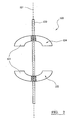
- FIG. 2 shows a mixing apparatus 100 according to the present invention.
- the mixing apparatus 100 comprises a vertical elongate shaft 120 rotatable about a longitudinal axis 121 on which are fixedly mounted a first impeller 122 and a second impeller 124 in a spaced apart arrangement. Both the first and the second impeller 122, 124 comprise a number of hydrofoil blades 125.
- Each impeller 122,124 comprises four radially extending blades 125 fixedly mounted on the shaft 120 for co-operating rotation about the longitudinal axis of the shaft, in use.
- Each blade 125 on each impeller 122,124 is a hydrofoil blade arranged so as to impel the surrounding fluid axially in the direction of the other impeller.
- the first or lower impeller 122 is thus an up-pumping impeller and the second or upper impeller 124 is a down-pumping impeller.
- the first or lower impeller 122 is thus an up-pumping impeller and the second or upper impeller 124 is a down-pumping impeller.
- the second or upper impeller 124 is a down-pumping impeller.
- any number of blades may be used on each of the said impellers, for example, 3, 4 or even 6 blades.
- Particularly suitable commercially available impellers are those known as MaxfloTM W, A315, A320 or A340 impellers.
- the first impeller 122 is mounted on the shaft 120 so that the concave face of the blades 125 face in an upward direction.
- the second impeller 124 is spaced along the shaft 120 and is mounted so that the concave face of the blades 125 face in a downwards direction.
- the distance between the first impeller 122 and the second impeller 124 is approximately the diameter of either of the said impellers 122, 124.
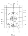
- FIG 3 shows the mixing apparatus 100 in a cylindrical vessel 112.
- a gas inlet 116 is located in the bottom-wall 132 of the vessel 112 adjacent to the base 132.
- the vessel 112 can be of any suitable alternative configuration, for example, it may be a hopper.
- the mixing apparatus 100 is centrally suspended in the vessel 112.
- mixing apparatus 100 Although only one mixing apparatus 100 is shown in Figure 3 , it will be appreciated that any number of mixing apparatus 100 could be used in the chamber 112. For example, two, three, or four mixing apparatus 100 may be mounted in the chamber 112.
- first or second impellers 122,124 may be mounted on the shaft 120 and in keeping with the object of the invention.
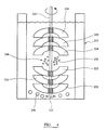
- the arrangement 200 shown in Figure 4 wherein a series of first impellers 222 and a series of second impellers 224 are mounted on the shaft 220.
- Any number of impellers 222,224 may be provided on the shaft 220.
- An alternative configuration would comprise pairs of impellers mounted on the shaft. Each pair would comprise a first impeller and a second impeller. There may be a number of pairs of impellers on any given shaft, for example, two, three, or four pairs.
- the fluid for example, gas
- the fluid may be introduced into the chamber through the base or the side wall thereof, being directed under and towards the first impeller.
- the first or the second impeller may be driven by a separate drive means so that the rotational speed of, for example, the first impeller, may be different to the rotational speed of the said other impeller.
- the diameter of the first and second impellers may not necessarily be the same in any one of the embodiments shown. Further, the optimum distance between two impellers is dependent upon the geometry of the vessel and the diameter of said impellers.
- the vessel 112,212 is filled with fluid 114,214.
- a gas 118,218 is then directed into the vessel 112,212 via gas inlet 116,216.
- the shaft 120,220 is rotated by a suitable drive means (not shown), so as to cause the first impeller 122,222 and the second impeller 124,224 to rotate about the longitudinal axis 121,221 of the shaft 120,220 in a liquid 114.
- the gas 118,218 enters the vessel 112,212 as large bubbles 150,215.
- Rotation of the first impeller 122,222 causes the large bubbles 150,215 to move in an axial direction towards the blades 125,225.
- the large bubbles 150,250 impact on the blades 125,225 and are broken up into a number of small bubbles 152,252 in the region of high turbulent energy dissipation. Small bubbles follow the liquid flow path which is initially axial then radial.
- the second impeller 124,224 causes axial flow in a downwards direction towards the first impeller 122,222. Due to the opposing axial flow paths created by said impellers, a central zone 160,260, or high turbulent energy dissipation zone, is established.
- the central zone 160,260 comprises an area of comparatively uniform high turbulent energy dissipation with high interfacial area to allow reaction between reactants in the liquid 114,214 and in reactants in the gas 118,218. Further, because the turbulent energy dissipation in the central zone 160,260 is maintained without much variation, a narrow size distribution of small bubbles is produced. Such a narrow size distribution enables the reactor performance to be predicted and controlled.
- the mixing apparatus 100,200 is particularly suited to carbonylation processes.
- Table 1 gives an example of resultant bubble size for a dual opposed Maxflo impeller system operating at various speeds, and at 4.2mm/sec. The bubble size was determined using a typical image capture camera. Table 1 N (rpm) 750 991 1200 d 10 ( ⁇ m) 296 330 394 d 32 ( ⁇ m) 450 510 500
Landscapes
- Chemical & Material Sciences (AREA)
- Chemical Kinetics & Catalysis (AREA)
- Organic Chemistry (AREA)
- Engineering & Computer Science (AREA)
- Dispersion Chemistry (AREA)
- Aviation & Aerospace Engineering (AREA)
- Oil, Petroleum & Natural Gas (AREA)
- Organic Low-Molecular-Weight Compounds And Preparation Thereof (AREA)
- Mixers Of The Rotary Stirring Type (AREA)
- Confectionery (AREA)
- Physical Or Chemical Processes And Apparatus (AREA)
- Catalysts (AREA)
- Low-Molecular Organic Synthesis Reactions Using Catalysts (AREA)
- Accessories For Mixers (AREA)
Abstract
Description
- The invention relates to a mixing apparatus. In particular, but not exclusively, the invention relates to an apparatus for dispersing gas in liquid.
- Many industrial processes incorporate an impeller driven mixing system, for example, processes for fermentation, hydrogenation, chlorination, oxidation, and carbonylation.
- Impeller driven mixing systems generally incorporate one impeller mounted on a rotating shaft. Such systems may be said to have an axial longitudinal flow parallel to the axis of the rotating shaft and/or a radial flow parallel to the radially extending blades mounted on the shaft. The impeller may thus be a radial flow impeller which projects fluid in a radial direction towards a wall of a chamber in which the impeller is housed, for example, a Chemineer BT-6™ turbine, or alternatively, the impeller may be an axial flow impeller which comprises radially extending blades that are pitched at an angle so as to direct the fluid flow in an axial direction. Examples of axial flow impellers include marine impellers and hydrofoil impellers. Mixed flow systems are known, where the impeller causes flow in both axial and radial directions. An example of a mixed flow impeller is the 45° pitched blade turbine. Such mixing systems can be used in liquid-liquid, liquid-solid, or liquid-gas reactions.
- A dual impeller system for dispersing a gas in a liquid, in a vessel, is known. Specifically, in a paper by Kuboi, entitled "The Power Drawn by Dual Impeller Systems Under Gassed and Ungassed Conditions" Fourth European Conference on Mixing, April 27-29 1982, the combination of two axially spaced 45° pitched blade turbines is disclosed whereby a first impeller is mounted below a second impeller on a common shaft. The impeller blades are orientated such that the first impeller projects liquid upwards and outwards and the second impeller projects liquid downwards and outwards. Under gassed conditions, as gas is introduced into the vessel, the first impeller causes the incoming flow of gas bubbles to split so that some of the flow is driven radially outwards towards the walls of the vessel, and some is driven axially upwards towards the second impeller.
- The effectiveness of the two impeller system under gassing conditions depends upon the speed of rotation of the impellers. At lower speeds it is possible that the bubbles that have been projected upwards by the first impeller are not affected by the second impeller. The second impeller is unable to overcome buoyancy forces and therefore the second impeller plays no part in the dispersion of gas in the liquid. Only when the rotational speed of the second impeller is increased are the buoyancy forces overcome. Disadvantageously, non-uniform dispersion of the gas in the liquid results. This is shown in
Figure 1 of the application. In order to achieve uniform dispersion, further disadvantageously, the rotational speed of the second impeller has to be sharply increased. -
US 2004/042942 discloses a reactor system for mixing a solid granular catalyst and a liquid phase. The system comprises a core in which is located a basket assembly. A shaft assembly comprising upper and lower impellers and blades is mounted in the basket assembly and is operable to urge flow outwardly to mix with a granular material. -
DE 20306404 discloses a multi-stirrer arrangement designed to be contactlessly, inductively or magnetically driven. The arrangement comprises a shaft having an upper stirrer tool and a lower stirrer tool. The two stirrer tools are identical but opposed being configured to cancel axial forces acting on the arrangement. - It is highly desirable to be able to achieve complete uniform dispersion in an industrial process. In industrial processes where gas/liquid mass transfer is an essential feature, this aids controllability and enhances reactor performance. In such processes, when the gas is well dispersed, a region of reasonably uniform turbulent kinetic eddy dissipation can exist in the liquid between and around the impellers which controls coalescence and breakup of the bubbles. If the gas dispersion is highly non-uniform, undesirable coalescence can result in a sharp increase in bubble size and therefore, the surface area for interface mass transfer to occur is reduced. Advantageously, a controlled turbulent kinetic energy dissipation field results in a narrow bubble size distribution over a range of impeller specific powers.
- It is an object of the present invention to provide a mixing apparatus which enables controllable mixing of fluids or solids whilst simultaneously providing an effective mixing environment.
- According to a first aspect of the present invention there is provided a mixing apparatus for mixing at least two fluids, the at least two fluids comprising a liquid and a gas, the mixing apparatus comprising a shaft rotatable about its longitudinal axis, a first and a second radially extending impeller mounted on the shaft and respectively axially spaced apart, the first impeller comprising a plurality of curved blades operable to move said fluids in an axial direction towards the second impeller, and the second impeller comprising a plurality of curved blades operable to move said fluids in an axial direction towards the first impeller, characterised in that said blades of each impeller are hydrofoil blades.
- Preferably, the blades on each impeller are inward pumping into the space between the impellers. In the case of a substantially vertical shaft, the lower impeller is, therefore, upward pumping and the upper impeller is downward pumping. Preferably, the blades of each impeller are hydrofoil blades. A suitable hydrofoil blade is the Chemineer Maxflo™ W. Alternatively, the Lightnin A315™, A320™ or A340™ may be used.
- Advantageously, due to the opposing axial flows created by the first impeller and the second impeller, a region of high turbulence is observed in a central mixing zone between said impellers. The high turbulence is maintained in this zone, and so there is little variation in the turbulence energy dissipation. Consequently, there is minimal variation in bubble size which results in a narrow size distribution of the bubbles in the central mixing zone. Advantageously, a narrow bubble size distribution enables the process or chemical reaction to be more easily controlled. This region provides a zone where the at least two fluids are brought together to be mixed. A chemical reaction can therefore be facilitated in the central mixing zone. The fluids may be liquid-solid, liquid-liquid, or liquid-gas. Preferably, the at least two fluids comprise a liquid and a gas.
- It is advantageous to provide a gas/liquid mixing environment where the bubble size is largely independent of the impeller specific power. In such a system the liquid mixing time may be varied independently of the bubble size.
- Preferably, the first impeller and the second impeller each comprise two or more curved blades, more preferably, three or more curved blades. Most preferably, are impellers with four curved blades. The provision of an impeller with a large number of curved blades increases the shear forces acting to break up large bubbles. The small bubbles produced have a smaller average bubble diameter than those produced with a first impeller and/or a second impeller with fewer curved blades and therefore, the available surface area for a reaction to occur is increased.
- Preferably, the diameter of the first impeller is the same as the diameter of the second impeller. Preferably, the diameter of the or each impeller is substantially half the diameter of the vessel in which said impeller is mounted.
- Advantageously, the smaller the diameter of the impeller, the greater the shear force created for a given power and therefore, a large number of small bubbles are produced which leads to an increase in available surface area for a reaction to occur.
- Preferably, the axial distance between the first impeller and the second impeller is at least one impeller diameter apart. In this configuration, the turbulence created by the opposing impellers is an equilibrium in the central mixing zone which allows for prediction of bubble size and therefore control of the reaction occurring.
- It is preferable that the total power drawn by the combination of impellers is low. Preferably, the impellers operate at a low power number, preferably substantially between 1 to 5, more preferably, substantially between 1 to 3, most preferably substantially 1.75. In so doing, the system consumes less energy than conventional systems which operate at power numbers of typically 3.2. The power may be measured using conventional equipment, for example, strain gauges.
- Preferably, when operating at a low power number complete uniform dispersed phase distribution is achieved. This is highly desirable and is because of the energy efficiency of the hydrofoil blades.
- Without being restricted by theory, one possible explanation for the efficiency of the invention is that the use of hydrofoil blades reduces tip vortices and converts more of the shaft energy into flow rather than turbulent kinetic energy, aiding complete dispersion.
- Preferably, the specific power used when the first impeller and the second impeller rotate is substantially between 50W/m3 to 900W/m3, more preferably, substantially between 100W/m3 to 800W/m3.
- Preferably, when dual opposed Maxflo type impellers are used in the system, the preferred specific power is substantially between 50W/m3 to 900W/m3. Preferably, when BT-6 type impellers are used, the preferred specific power is substantially between 400W/m3 to 3200W/m3. At such specific powers, a narrow bubble size distribution is maintained and the reaction is controlled.
- Preferably, when dual opposed Maxflo impellers are used, the arithmetic mean size (d10) is substantially between 250µm to 550µm and the surface volume mean diameter (d32) is substantially between 400µm to 750µm. Preferably, when operating at substantially 750rpm, the d10 is substantially between 250µm to 350µm, most preferably substantially 296µm, and preferably, the d32 is substantially between 400µm to 500µm, most preferably substantially 450µm. Preferably, when operating at substantially 991rpm, the d10 is substantially between 300µm to 400µm, most preferably substantially 330µm, and preferably, the d32 is substantially between 460µm to 560µm, most preferably substantially 510µm. Preferably, when operating at substantially 1200rpm, the d10 is substantially between 350µm to 450µm, most preferably substantially 394µm, and preferably, the d32 is substantially between 450µm to 550µm, most preferably substantially 500µm.
- Preferably, when BT-6 type impellers are used, the d10 is substantially between 250µm to 1500µm. Particularly, when operating at substantially 251rpm, preferably the d10 is substantially between 550µm to 650µm, most preferably substantially 633µm, and the d32 is preferably substantially between 800pm to 1000µm, most preferably substantially 978µm. Preferably, when operating at substantially 380rpm, the d10 is preferably substantially between 800µm to 900µm, most preferably substantially 841µm, and the d32 is preferably substantially between 1000µm to 1500µm, most preferably substantially 1345pm. At substantially 500rpm, the d10 is preferably substantially between 500µm to 600µm, most preferably substantially 597µm, and the d32 is preferably substantially between 700µm to 800µm, most preferably substantially 721µm. Preferably, when operating at substantially 765rpm, the d10 is preferably substantially between 300µm to 400µm, most preferably substantially 378µm, and the d32 is preferably substantially between 400µm to 500µm, most preferably substantially 445µm.
- In a reactor where gas is sparged into an agitated liquid medium, preferably, the sparged gas rate is substantially between 0.05 to 1.0 m3/s, preferably substantially between 0.1 to 0.5m3/s, most preferably substantially 0.13m3/s at an impeller speed of preferably between 50rpm to 1200rpm, most preferably substantially 50rpm to 200rpm.
- A key parameter used in the design of gas-liquid mixing systems is the critical dispersion speed. This is the minimum impeller speed required to ensure uniform dispersion of the gas bubbles. The critical dispersion speed for achieving dispersion in a dual opposed flow hydrofoil system in a vessel having a diameter of preferably substantially between 1 to 10m, more preferably, substantially between 2 to 5m, is preferably substantially between 1 to 100rpm, preferably substantially between 5 to 50rpm, more preferably substantially between 10 to 20rpm, most preferably substantially 14rpm.
- Accordingly, in a further aspect of the present invention there is provided a use of a mixing apparatus according to the first aspect of the invention for mixing a fluid into the liquid phase in a chemical reaction system comprising the liquid phase. Preferably, the fluid is a solid or most preferably, the fluid is a gas.
- Preferably, the liquid phase comprises at least one liquid phase reactant for reacting with a gas introduced into the liquid phase, as well as at least one liquid phase reaction product. Preferably, the liquid phase includes a gas introduced therein. Preferably, the said gas comprises one or more reactants capable of reacting with the said one or more reactants. Preferably, the liquid phase comprises a catalyst system. Preferably, the reaction system is a carbonylation reaction system such as one referred to in European patents and patent applications
EP-A-0055875 ,EP-A-0106379 ,EP-A-0235864 ,EP-A-0274795 ,EP-A-0499329 ,EP-A-0386833 ,EP-A-0441447 ,EP-A-0489472 ,EP-A-0282142 ,EP-A-0227160 ,EP-A-0495547 ,EP-A-0495548 ,EP-A-1651587 ,EP-A-1565425 ,EP-A-1554039 ,EP-A-1534427 ,EP-A-1527038 ,EP-A-1204476 ,W02005118519 andW02005079981 . - Preferably, the reaction system is a carbonylation process comprising carbonylating an ethylenically unsaturated compound with carbon monoxide in the presence of a source of hydroxyl groups, preferably, methanol, and a catalyst system comprising (a) a bidentate phosphine, arsine or stibine ligand, and (b) a catalytic metal selected from a
group 8, 9 or 10 metal or a compound thereof, preferably palladium. Preferably, the phosphine ligand is selected from 1,2-bis-(di-tert-butylphosphinomethyl)benzene, 1,2-bis-(di-tert-pentylphosphinomethyl)benzene, 1,2-bis-(di-tert-butylphosphinomethyl)naphthalene, 1,2 bis(diadamantylphosphinomethyl)benzene, 1,2 bis(di-3,5-dimethyladamantylphosphinomethyl)benzene, 1,2 bis(di-5-tert-butyladamantylphosphinomethyl)benzene, 1,2 bis(1-adamantyl tert-butyl-phosphinomethyl)benzene, 1-(diadamantylphosphinomethyl)-2-(di-tert-butylphosphinomethyl)benzene, 1-(di-tert-butylphosphinomethyl)-2-(dicongressylphosphinomethyl)benzene, 1-(di-tert-butylphosphinomethyl)-2-(phospha-adamantyl-P-methyl)benzene, 1-(diadamantylphosphinomethyl)-2-(phospha-adamantyl-P-methyl)benzene, 1-(tert-butyladamantylphosphinomethyl)-2-(di-adamantylphosphinomethyl)benzene and 1-[(P-(2,2,6,6,-tetra-methylphosphinan-4-one)phosphinomethyl)]-2-(phospha-adamantyl-P-methyl)benzene, wherein "phospha-adamantyl" is selected from 2-phospha-1,3,5,7-tetramethyl-6,9,10-trioxadamantyl,2-phospha-1,3,5-trimethyl-6,9,10 trioxadamantyl, 2-phospha-1,3,5,7-tetra(trifluoromethyl)-6,9,10-trioxadamantyl or 2-phospha-1,3,5-tri(trifluoromethyl)-6,9,10-trioxadamantyl; 1,2-bis-(dimethylaminomethyl)ferrocene, 1,2-bis-(ditertbutylphosphinomethyl)ferrocene, 1-hydroxymethyl-2-dimethylaminomethylferrocene, 1,2-bis-(ditertbutylphosphinomethyl)ferrocene, 1-hydroxymethyl-2,3-bis-(dimethylaminomethyl)ferrocene, 1,2,3-tris-(ditertbutylphosphinomethyl)ferrocene, 1,2-bis-(dicyclohexylphosphinomethyl)ferrocene, 1,2-bis-(di-isobutylphosphinomethyl)ferrocene, 1,2-bis-(dicyclopentylphosphinomethyl)ferrocene, 1,2-bis-(diethylphosphinomethyl)ferrocene, 1,2-bis(di-isopropylphosphinomethyl)ferrocene, 1,2-bis-(dimethylphosphinomethyl)ferrocene, 1,2-bis-(di-(1,3,5,7-tetramethyl-6,9,10-trioxa-2-phosphaadamantylmethyl))ferrocene, 1,2-bis-(dimethylaminomethyl)ferrocene-bismethyl iodide, 1,2-bis(dihydroxymethylphosphinomethyl)ferrocene, 1,2-bis(diphosphinomethyl)ferrocene, 1,2-bis-α,α-(P-(2,2,6,6,-tetramethylphosphinan-4-one))dimethylferrocene, and 1,2-bis-(di-1,3,5,7-tetramethyl-6,9,10-trioxa-2-phosphaadamantylmethyl))benzene; cis-1,2-bis(di-t-butylphosphinomethyl)-4,5- dimethyl cyclohexane; cis-1,2-bis(di-t-butylphosphinomethyl)-5- methylcyclopentane; cis-1,2-bis(2-phosphinomethyl-1,3,5,7-tetramethyl-6,9,10-trioxa-adamantyl)-4,5-dimethylcyclohexane; cis-1,2-bis(2-phosphinomethyl-1,3,5,7-tetramethyl-6,9,10-trioxaadamantyl) 5-methylcyclopentane; cis-1,2-bis(di-adamantylphosphinomethyl)-4,5 dimethylcyclohexane; cis-1,2-bis(di-adamantylphosphinomethyl)-5-methyl cyclopentane; cis-1- (P,P adamantyl, t-butyl phosphinomethyl)-2-(di-t-butylphosphinomethyl)-4,5-dimethylcyclohexane; cis-1- (P,P adamantyl, t-butyl phosphinomethyl)-2-(di-t-butylphosphinomethyl)-5-methylcyclopentane; cis-1- (2-phosphinomethyl-1,3,5,7-tetramethyl-6,9,10-trioxa-adamantyl) - 2 - (di-t-butylphosphinomethyl)4,5- dimethylcyclohexane; cis-1- (2-phosphinomethyl-1,3,5,7-tetramethyl-6,9,10-trioxaadamantyl) - 2 - (di-t-butylphosphinomethyl)-5-methyl cyclopentane; cis-1-(2-phosphinomethyl-1,3,5,7-tetramethyl-6,9,10-trioxa-adamantyl) -2-(diadamantylphosphinomethyl)-5-methyl cyclohexane; cis-1-(2-phosphinomethyl-1,3,5,7-tetramethyl-6,9,10-trioxaadamantyl)-2-(diadamantylphosphinomethyl)-5-methyl cyclopentane; cis-1-(2-phosphinomethyl-1,3,5,7-tetramethyl-6,9,10-trioxa-adamantyl) -2-(diadamantylphosphinomethyl)cyclobutane; cis-1-(di-t-butylphosphinomethyl)-2- (diadamantylphosphinomethyl)-4,5-dimethyl cyclohexane; cis-1-(di-t-butylphosphinomethyl)-2- (diadamantylphosphinomethyl)-5-methyl cyclopentane; cis-1,2-bis(2-phospha-1,3,5-trimethyl-6,9,10-trioxatricyclo-{3.3.1.1[3.7]}decyl)-4,5-dimethyl cyclohexane; cis-1,2-bis(2-phospha-1,3,5-trimethyl-6,9,10-trioxatricyclo-{3.3.1.1[3.7]}decyl)-5-methyl cyclopentane; cis-1-(2-phospha-1,3,5-trimethyl-6,9,10-trioxatricyclo-{3.3.1.1[3.7]}decyl)-2-(di-t-butylphosphinomethyl)-4,5-dimethyl cyclohexane; cis-1-(2-phospha-1,3,5-trimethyl-6,9,10-trioxatricyclo-{3.3.1.1[3.7]}decyl)-2-(di-t-butylphosphinomethyl)-5-methyl cyclopentane; cis-1-(2-phospha-1,3,5-trimethyl-6,9,10-trioxatricyclo-{3.3.1.1[3.7]}decyl)-2-(diadamantylphosphinomethyl)-4,5-dimethyl cyclohexane; cis-1-(2-phospha-1,3,5-trimethyl-6,9,10-trioxatricyclo-{3.3.1.1[3.7]}decyl)-2-(diadamantylphosphinomethyl)-5-methyl cyclopentane; cis-1,2-bis-perfluoro(2-phospha-1,3,5,7-tetramethyl-6,9,10-trioxatricyclo{3.3.1.1[3.7]}-decyl)-4,5-dimethyl cyclohexane; cis-1,2-bis-perfluoro(2-phospha-1,3,5,7-tetramethyl-6,9,10-trioxatricyclo{3.3.1.1[3.7]}decyl)-5-methyl cyclopentane; cis-1,2-bis- (2-phospha-1,3,5,7-tetra(trifluoro-methyl)-6,9,10-trioxatricyclo{3.3.1.1[3.7]}decyl)-4,5-dimethyl cyclohexane; cis-1,2-bis- (2-phospha-1,3,5,7-tetra(trifluoro-methyl)-6,9,10-trioxatricyclo{3.3.1.1[3.7]}decyl)-5-methyl cyclopentane; cis-1,2-bis(di-t-butylphosphinomethyl)cyclohexane; cis-1,2-bis(di-t-butylphosphinomethyl)cyclopentane; cis-1,2-bis(di-t-butylphosphinomethyl)cyclobutane; cis-1,2-bis(2-phosphinomethyl-1,3,5,7-tetramethyl-6,9,10-trioxaadamantyl)cyclohexane; cis-1,2-bis(2-phosphinomethyl-1,3,5,7-tetramethyl-6,9,10-trioxa-adamantyl)cyclopentane; cis-1,2-bis(2-phosphinomethyl-1,3,5,7-tetramethyl-6,9,10-trioxa-adamantyl)cyclobutane; cis-1,2-bis(di-adamantylphosphinomethyl)cyclohexane; cis-1,2-bis(di-adamantylphosphinomethyl)cyclopentane; cis-1,2-bis(di-adamantylphosphinomethyl)cyclobutane; cis-1- (P,P-adamantyl, t-butyl-phosphinomethyl)-2-(di-t-butylphosphinomethyl)cyclohexane; cis-1- (P,P-adamantyl, t-butyl-phosphinomethyl)-2-(di-t-butylphosphinomethyl)cyclopentane; cis-1- (P,P-adamantyl, t-butyl-phosphinomethyl)-2-(di-t-butylphosphinomethyl)cyclobutane; cis-1- (2-phosphinomethyl-1,3,5,7-tetramethyl-6,9,10-trioxaadamantyl) - 2 - (di-t-butylphosphinomethyl) cyclohexane; cis-1- (2-phosphinomethyl-1,3,5,7-tetramethyl-6,9,10-trioxa-adamantyl) - 2 - (di-t-butylphosphinomethyl)cyclopentane; cis-1- (2-phosphinomethyl-1,3,5,7-tetramethyl-6,9,10-trioxaadamantyl) - 2 - (di-t-butylphosphinomethyl) cyclobutane; cis-1-(2-phosphinomethyl-1,3,5,7-tetramethyl-6,9,10-trioxa-adamantyl) -2-(diadamantylphosphinomethyl)cyclohexane; cis-1-(2-phosphinomethyl-1,3,5,7-tetramethyl-6,9,10-trioxaadamantyl)-2-(diadamantylphosphinomethyl)cyclopentane; cis-1-(2-phosphinomethyl-1,3,5,7-tetramethyl-6,9,10-trioxa-adamantyl) -2-(diadamantylphosphinomethyl)cyclobutane; cis-1-(di-t-butylphosphinomethyl)-2-(diadamantylphosphinomethyl)cyclohexane; cis-1-(di-t-butylphosphinomethyl)-2-(diadamantylphosphinomethyl)cyclopentane; cis-1-(di-t-butylphosphinomethyl)-2-(diadamantylphosphinomethyl)cyclobutane; cis-1,2-bis(2-phospha-1,3,5-trimethyl-6,9,10-trioxatricyclo{3.3.1.1[3.7]}decyl)cyclohexane; cis-1,2-bis(2-phospha-1,3,5-trimethyl-6,9,10-trioxatricyclo-{3.3.1.1[3.7]}decyl)cyclopentane; cis-1,2-bis(2-phospha-1,3,5-trimethyl-6,9,10-trioxatricyclo-{3.3.1.1[3.7]}decyl)cyclobutane; cis-1-(2-phospha-1,3,5-trimethyl-6,9,10-trioxatricyclo-{3.3.1.1[3.7]}decyl)-2-(di-t-butylphosphinomethyl)cyclohexane; cis-1-(2-phospha-1,3,5-trimethyl-6,9,10-trioxatricyclo-{3.3.1.1[3.7]}decyl)-2-(di-t-butylphosphinomethyl)cyclopentane; cis-1-(2-phospha-1,3,5-trimethyl-6,9,10-trioxatricyclo-{3.3.1.1[3.7]}decyl)-2-(di-t-butylphosphinomethyl)cyclobutane; cis-1-(2-phospha-1,3,5-trimethyl-6,9,10-trioxatricyclo-{3.3.1.1[3.7]}decyl)-2-(diadamantylphosphinomethyl)cyclohexane; cis-1-(2-phospha-1,3,5-trimethyl-6,9,10-trioxatricyclo-{3.3.1.1[3.7]}decyl)-2-(diadamantylphosphinomethyl)cyclopentane; cis-1-(2-phospha-1,3,5-trimethyl-6,9,10-trioxatricyclo-{3.3.1.1[3.7]}decyl)-2-(diadamantylphosphinomethyl)cyclobutane; cis-1,2-bis-perfluoro(2-phospha-1,3,5,7-tetramethyl-6,9,10-trioxatricyclo{3.3.1.1[3.7]}-decyl)cyclohexane; cis-1,2-bis-perfluoro(2-phospha-1,3,5,7-tetramethyl-6,9,10-trioxatricyclo{3.3.1.1[3.7]}decyl)cyclopentane; cis-1,2-bis-perfluoro(2-phospha-1,3,5,7-tetramethyl-6,9,10-trioxatricyclo{3.3.1.1[3.7]}decyl)cyclobutane; cis-1,2-bis- (2-phospha-1,3,5,7-tetra(trifluoro-methyl)-6,9,10-trioxatricyclo{3.3.1.1[3.7]}decyl)cyclohexane; cis-1,2-bis- (2-phospha-1,3,5,7-tetra(trifluoro-methyl)-6,9,10-trioxatricyclo{3.3.1.1[3.7]}decyl)cyclopentane; and cis-1,2-bis- (2-phospha-1,3,5,7-tetra(trifluoro-methyl)-6,9,10-trioxatricyclo{3.3.1.1[3.7]}decyl)cyclobutane; (2-exo, 3-exo)-bicyclo[2.2.1]heptane-2,3-bis(di-tert-butylphosphinomethyl) and (2-endo, 3-endo)-bicyclo[2.2.1]heptane-2,3-bis(di-tert-butylphosphinomethyl). - The bubble size produced by the invention may be small and therefore a large surface area is provided for interface mass transfer to take place. Furthermore, because the bubble size distribution is narrow with small deviation, the carbonylation reaction can be controlled.
- All of the features described herein may be combined with any of the above aspects, in any combination unless such combinations are mutually exclusive.
- An embodiment of the invention will now be described, by way of example only, with reference to the accompanying drawings, wherein:
-
Figure 1 is a schematic sectional side view of a prior art mixing apparatus; -
Figure 2 is a schematic sectional side view of a mixing apparatus according to the invention; -
Figure 3 is a schematic sectional side view of a mixing apparatus according to the invention in use; and -
Figure 4 is a further schematic sectional side view of a mixing apparatus according to the invention in use. -
Figure 1 shows a priorart mixing apparatus 10 in use in avessel 12 containing a liquid 14. Thevessel 12 has aninlet 16 through which agas 18 is sparged into the liquid 14. The mixingapparatus 10 comprises a verticalelongate shaft 20 rotatable about alongitudinal axis 21 on which are fixedly mounted afirst impeller 22 and asecond impeller 24 in spaced apart relation. Thefirst impeller 22 is mounted above thesecond impeller 24. Both the first and thesecond impellers - In use, said impellers must rotate at the same speed. The
first impeller 22 causes incoming gas bubbles 26 to flow in a both an axial and radial direction. The axial component of the flow creates momentum, which along with buoyancy, prevents thesecond impeller 24 from operating effectively. The momentum and buoyancy is only overcome by increasing the speed of theimpellers gas 18 in the liquid 14 as shown inFigure 1 by the lines A. Non-uniform dispersion of the liquid 14 in thegas 18 is undesirable because the mixing process cannot be controlled. -
Figure 2 shows amixing apparatus 100 according to the present invention. The mixingapparatus 100 comprises a verticalelongate shaft 120 rotatable about alongitudinal axis 121 on which are fixedly mounted afirst impeller 122 and asecond impeller 124 in a spaced apart arrangement. Both the first and thesecond impeller hydrofoil blades 125. Each impeller 122,124 comprises four radially extendingblades 125 fixedly mounted on theshaft 120 for co-operating rotation about the longitudinal axis of the shaft, in use. Eachblade 125 on each impeller 122,124 is a hydrofoil blade arranged so as to impel the surrounding fluid axially in the direction of the other impeller. The first orlower impeller 122 is thus an up-pumping impeller and the second orupper impeller 124 is a down-pumping impeller. Although only twoblades 125 can be seen in the figure, it will be understood by a skilled person, that any number of blades may be used on each of the said impellers, for example, 3, 4 or even 6 blades. Particularly suitable commercially available impellers are those known as Maxflo™ W, A315, A320 or A340 impellers. - The
first impeller 122 is mounted on theshaft 120 so that the concave face of theblades 125 face in an upward direction. Thesecond impeller 124 is spaced along theshaft 120 and is mounted so that the concave face of theblades 125 face in a downwards direction. The distance between thefirst impeller 122 and thesecond impeller 124 is approximately the diameter of either of the saidimpellers -
Figure 3 shows themixing apparatus 100 in acylindrical vessel 112. Agas inlet 116 is located in the bottom-wall 132 of thevessel 112 adjacent to thebase 132. It will be appreciated that thevessel 112 can be of any suitable alternative configuration, for example, it may be a hopper. The mixingapparatus 100 is centrally suspended in thevessel 112. - Although only one
mixing apparatus 100 is shown inFigure 3 , it will be appreciated that any number of mixingapparatus 100 could be used in thechamber 112. For example, two, three, or fourmixing apparatus 100 may be mounted in thechamber 112. - It will also be understood that any number of first or second impellers 122,124 may be mounted on the
shaft 120 and in keeping with the object of the invention. For example, the arrangement 200 shown inFigure 4 , wherein a series offirst impellers 222 and a series ofsecond impellers 224 are mounted on theshaft 220. Any number of impellers 222,224 may be provided on theshaft 220. - An alternative configuration would comprise pairs of impellers mounted on the shaft. Each pair would comprise a first impeller and a second impeller. There may be a number of pairs of impellers on any given shaft, for example, two, three, or four pairs. In such an arrangement, the fluid, for example, gas, may be introduced into the chamber through the base or the side wall thereof, being directed under and towards the first impeller.
- The first or the second impeller may be driven by a separate drive means so that the rotational speed of, for example, the first impeller, may be different to the rotational speed of the said other impeller.
- The diameter of the first and second impellers may not necessarily be the same in any one of the embodiments shown. Further, the optimum distance between two impellers is dependent upon the geometry of the vessel and the diameter of said impellers.
- In use, as in the illustrated carbonylation reaction, the vessel 112,212 is filled with fluid 114,214. A gas 118,218 is then directed into the vessel 112,212 via gas inlet 116,216. The shaft 120,220 is rotated by a suitable drive means (not shown), so as to cause the first impeller 122,222 and the second impeller 124,224 to rotate about the longitudinal axis 121,221 of the shaft 120,220 in a liquid 114.
- The gas 118,218 enters the vessel 112,212 as large bubbles 150,215. Rotation of the first impeller 122,222 causes the large bubbles 150,215 to move in an axial direction towards the blades 125,225. The large bubbles 150,250 impact on the blades 125,225 and are broken up into a number of small bubbles 152,252 in the region of high turbulent energy dissipation. Small bubbles follow the liquid flow path which is initially axial then radial.
- The second impeller 124,224 causes axial flow in a downwards direction towards the first impeller 122,222. Due to the opposing axial flow paths created by said impellers, a central zone 160,260, or high turbulent energy dissipation zone, is established. The central zone 160,260 comprises an area of comparatively uniform high turbulent energy dissipation with high interfacial area to allow reaction between reactants in the liquid 114,214 and in reactants in the gas 118,218. Further, because the turbulent energy dissipation in the central zone 160,260 is maintained without much variation, a narrow size distribution of small bubbles is produced. Such a narrow size distribution enables the reactor performance to be predicted and controlled.
- The mixing apparatus 100,200 is particularly suited to carbonylation processes.
- Table 1 gives an example of resultant bubble size for a dual opposed Maxflo impeller system operating at various speeds, and at 4.2mm/sec. The bubble size was determined using a typical image capture camera.
Table 1 N (rpm) 750 991 1200 d10 (µm) 296 330 394 d32 (µm) 450 510 500 - It is a distinct advantage to be able to control the reaction occurring between two fluids, particularly a liquid and a gas. It is also especially favorable to be able to promote effective and efficient mixing and interphase mass transfer between at least two fluids. When applied to industrial processes, such advantages are of high commercial value.
Claims (17)
- A mixing apparatus (100) for mixing at least two fluids, the at least two fluids comprising a liquid and a gas, the mixing apparatus (100) comprising a shaft (120) rotatable about its longitudinal axis (121), a first and a second radially extending impeller (122,124) mounted on the shaft (120) and respectively axially spaced apart, the first impeller (122) comprising a plurality of curved blades (125) operable to move said fluids in an axial direction towards the second impeller (124), and the second impeller (124) comprising a plurality of curved blades (125) operable to move said fluids in an axial direction towards the first impeller (122), characterised in that said blades (125) of each impeller are hydrofoil blades.
- A mixing apparatus as claimed in claim 1, characterised in that the blades (125) on each impeller are operable to be inward pumping into the space between the impellers (122,124).
- A mixing apparatus as claimed in any one of the preceding claims, characterised in that the first impeller (122) and the second impeller (124) each comprise two or more curved blades (125).
- A mixing apparatus as claimed in any one of the preceding claims, characterised in that the diameter of the first impeller (122) is the same as the diameter of the second impeller (124).
- A mixing apparatus as claimed in any one of the preceding claims, characterised in that the axial distance between the first impeller (122) and the second impeller (124) is at least one impeller diameter apart.
- A mixing apparatus as claimed in any one of the preceding claims, characterised in that said impellers (122,124) are operable at a power number 1.75.
- A mixing apparatus as claimed in any one of the preceding claims, characterised in that the specific power used when the first impeller (122) and the second impeller (124) are operable to rotate is between 100W/m3 to 800W/m3.
- A mixing apparatus as claimed in any one of the preceding claims, characterised in that when dual opposed Maxflo impellers are used, the arithmetic mean size (d10) is between 250µm to 550µm and the surface volume mean diameter (d32) is between 400µm to 750µm.
- A mixing apparatus as claimed in any one of the preceding claims, characterised in that when BT-6 type impellers are used, the d10 is between 250µm to 1500µm.
- A mixing apparatus as claimed in claim 9, characterised in that when operable at 765rpm, the d10 is 378µm, and the d32 is 445µm.
- A mixing apparatus as claimed in any one of the preceding claims, characterised in that the sparged gas rate is between 0.05 to 1.0 m3/s.
- A mixing apparatus as claimed in claim 11, characterised in that the sparged gas rate is 0.13m3/s at an impeller speed of 50rpm to 200rpm.
- A mixing apparatus as claimed in any one of the preceding claims, characterised in that a critical dispersion speed in a vessel having a diameter of between 2 to 5m, is between 10 to 20rpm.
- A use of a mixing apparatus according to any one of the preceding claims for mixing a fluid into a liquid phase in a chemical reaction system comprising the liquid phase.
- A use of a mixing apparatus as claimed in claim 14, characterised in that the liquid phase comprises at least one liquid phase reactant for reacting with a gas introduced into the liquid phase, as well as at least one liquid phase reaction product.
- A use of a mixing apparatus as claimed in claims 14 or 15, characterised in that the liquid phase comprises a catalyst system.
- A use of a mixing apparatus as claimed in any one of claims 14 to 16, characterised in that the reaction system is a carbonylation process comprising carbonylating an ethylenically unsaturated compound with carbon monoxide in the presence of a source of hydroxyl groups, and a catalyst system comprising (a) a bidentate phosphine, arsine or stibine ligand, and (b) a catalytic metal selected from a group 8, 9 or 10 metal or a compound thereof.
Priority Applications (1)
| Application Number | Priority Date | Filing Date | Title |
|---|---|---|---|
| PL07732561T PL2018218T3 (en) | 2006-05-10 | 2007-04-25 | Mixing apparatus for mixing at least two fluids, and its use |
Applications Claiming Priority (2)
| Application Number | Priority Date | Filing Date | Title |
|---|---|---|---|
| GB0609219A GB2437930A (en) | 2006-05-10 | 2006-05-10 | Mixing apparatus |
| PCT/GB2007/001524 WO2007129023A1 (en) | 2006-05-10 | 2007-04-25 | Mixing apparatus |
Publications (2)
| Publication Number | Publication Date |
|---|---|
| EP2018218A1 EP2018218A1 (en) | 2009-01-28 |
| EP2018218B1 true EP2018218B1 (en) | 2011-11-23 |
Family
ID=36637204
Family Applications (1)
| Application Number | Title | Priority Date | Filing Date |
|---|---|---|---|
| EP07732561A Not-in-force EP2018218B1 (en) | 2006-05-10 | 2007-04-25 | Mixing apparatus for mixing at least two fluids, and its use |
Country Status (20)
| Country | Link |
|---|---|
| US (2) | US20090208390A1 (en) |
| EP (1) | EP2018218B1 (en) |
| JP (2) | JP5490528B2 (en) |
| KR (1) | KR101431600B1 (en) |
| CN (1) | CN101443100B (en) |
| AT (1) | ATE534456T1 (en) |
| AU (1) | AU2007246957B2 (en) |
| BR (1) | BRPI0711430A2 (en) |
| CA (1) | CA2650969C (en) |
| EA (1) | EA015826B1 (en) |
| ES (1) | ES2375233T3 (en) |
| GB (1) | GB2437930A (en) |
| MX (1) | MX2008014170A (en) |
| MY (1) | MY149061A (en) |
| NO (1) | NO20084866L (en) |
| PL (1) | PL2018218T3 (en) |
| SG (1) | SG174060A1 (en) |
| TW (1) | TWI429481B (en) |
| WO (1) | WO2007129023A1 (en) |
| ZA (1) | ZA200809066B (en) |
Families Citing this family (11)
| Publication number | Priority date | Publication date | Assignee | Title |
|---|---|---|---|---|
| EP2216395A1 (en) | 2009-02-09 | 2010-08-11 | Lonza Biologics plc. | Bioreactor for the cultivation of mammalian cells |
| CN103651237B (en) * | 2012-09-05 | 2016-12-21 | 曾进辉 | A kind of return stirring mechanism and micro-bubble generator |
| JP6159577B2 (en) * | 2013-05-24 | 2017-07-05 | 佐竹化学機械工業株式会社 | Gas-liquid stirring blade |
| JP6534665B2 (en) * | 2014-07-01 | 2019-06-26 | 佐竹化学機械工業株式会社 | Reciprocating motion stirring device having a fine bubble generating device |
| KR102256402B1 (en) * | 2018-10-15 | 2021-05-25 | 한화솔루션 주식회사 | Batch reactor |
| EP3962638A4 (en) * | 2019-05-03 | 2023-01-11 | Philadelphia Mixing Solutions, LLC | Reaction mixer |
| CN112479815A (en) * | 2019-09-12 | 2021-03-12 | 南京延长反应技术研究院有限公司 | A kind of reaction system and process for preparing butanol and octanol based on micro-interface enhanced carbonylation of propylene |
| JP7555059B2 (en) * | 2020-06-02 | 2024-09-24 | 株式会社フォーティー科研 | Bubble generating device and bubble generating method |
| WO2024252434A1 (en) * | 2023-06-06 | 2024-12-12 | Aquasoil S.R.L. | Process and system for degrading a chemical compound in a liquid stream |
| CN116983871B (en) * | 2023-09-20 | 2023-12-01 | 常州登达适医疗科技有限公司 | Gas-liquid mixing and stirring device and stirring method thereof |
| CN117160276A (en) * | 2023-10-18 | 2023-12-05 | 河络新图生物科技(上海)有限公司 | Rotor for biological reaction |
Family Cites Families (43)
| Publication number | Priority date | Publication date | Assignee | Title |
|---|---|---|---|---|
| CH332926A (en) * | 1955-09-22 | 1958-09-30 | Kreuzer Emil | Agitator |
| US3330818A (en) * | 1963-02-18 | 1967-07-11 | Monsanto Co | Elimination of fouling in ziegler polymerizations |
| US3252689A (en) * | 1964-06-10 | 1966-05-24 | Diamond Alkali Co | Method and apparatus for mixing and distributing liquids |
| US4013273A (en) * | 1973-12-19 | 1977-03-22 | The International Nickel Company, Inc. | Method of, and mixer for intimate blending of fine, dry, particulate solid materials with moist wet or slurried particulate solid materials |
| US4004786A (en) * | 1975-05-16 | 1977-01-25 | Barnard & Leas Manufacturing Co. Inc. | Stirring device |
| US4401645A (en) * | 1979-02-28 | 1983-08-30 | Joy Manufacturing Company | Lime slaking method |
| DE3175174D1 (en) | 1981-01-06 | 1986-09-25 | Shell Int Research | Process for the carbonylation of olefins |
| US4468130A (en) * | 1981-11-04 | 1984-08-28 | General Signal Corp. | Mixing apparatus |
| CA1231346A (en) | 1982-09-30 | 1988-01-12 | Eit Drent | Process for the carbonylation of olefinically unsaturated compounds with a palladium catalyst |
| US4594228A (en) * | 1984-05-21 | 1986-06-10 | The Standard Oil Company | Mixing apparatus |
| JPS6245330A (en) * | 1985-08-23 | 1987-02-27 | Tokushu Kika Kogyo Kk | Shearing type stirrer |
| GB8531624D0 (en) | 1985-12-23 | 1986-02-05 | Shell Int Research | Carbonylation of ethylenically unsaturated compounds |
| GB8605034D0 (en) | 1986-02-28 | 1986-04-09 | Shell Int Research | Carbonylation of compounds |
| KR880007426A (en) | 1986-12-24 | 1988-08-27 | 오노 알버어스 | Carbonylation Method of Olefinic Unsaturated Compound Using Palladium Catalyst |
| GB8705699D0 (en) | 1987-03-11 | 1987-04-15 | Shell Int Research | Carbonylation of olefinically unsaturated compounds |
| US5145255A (en) * | 1987-05-19 | 1992-09-08 | Mitsubishi Jukogoyo Kabushiki Kaisha | Stirring apparatus and stirring tower type apparatus for polmerization reactions |
| KR0144567B1 (en) | 1989-03-03 | 1998-07-15 | 오노 알버어스 | Catalyst system for carbonylation |
| US4934828A (en) * | 1989-06-07 | 1990-06-19 | Ciba-Geigy Corporation | Apparatus for mixing viscous materials |
| CA2034971A1 (en) | 1990-02-05 | 1991-08-06 | Eit Drent | Carbonylation catalyst system |
| CA2055628A1 (en) | 1990-12-03 | 1992-06-04 | Eit Drent | Carbonylation process and catalyst composition |
| EP0495547B1 (en) | 1991-01-15 | 1996-04-24 | Shell Internationale Researchmaatschappij B.V. | Carbonylation of olefins |
| ES2077337T3 (en) | 1991-01-15 | 1995-11-16 | Shell Int Research | PROCEDURE FOR THE CARBONILATION OF OLEPHINS. |
| EP0499329B1 (en) | 1991-02-15 | 1994-05-04 | Shell Internationale Researchmaatschappij B.V. | Carbonylation catalyst system |
| JPH078776A (en) | 1993-04-30 | 1995-01-13 | Kansai Kagaku Kikai Seisaku Kk | Stirring blade |
| DE4421478C2 (en) * | 1994-06-20 | 1998-10-01 | Netzsch Erich Holding | Propeller mill |
| JPH0810597A (en) | 1994-06-29 | 1996-01-16 | Fuji Electric Co Ltd | Device for mixing and transferring gas and liquid |
| JP3584582B2 (en) | 1995-11-28 | 2004-11-04 | 富士ゼロックス株式会社 | Powder mixing apparatus and toner manufacturing method |
| JP3210877B2 (en) | 1997-02-28 | 2001-09-25 | 中国塗料株式会社 | Stirrer and tank with stirrer |
| US5972661A (en) * | 1998-09-28 | 1999-10-26 | Penn State Research Foundation | Mixing systems |
| GB9918229D0 (en) | 1999-08-04 | 1999-10-06 | Ici Plc | Improvements relating to metal-compound catalysed processes |
| MY127093A (en) * | 2000-05-17 | 2006-11-30 | Lucite Int Uk Ltd | Bidentate ligands useful in catalyst systems |
| US6796707B2 (en) * | 2002-02-26 | 2004-09-28 | Spx Corporation | Dual direction mixing impeller and method |
| JP4112908B2 (en) * | 2002-06-07 | 2008-07-02 | 株式会社日立プラントテクノロジー | Continuous stirring device and continuous polycondensation method of polycondensation resin |
| GB0228018D0 (en) * | 2002-11-30 | 2003-01-08 | Lucite Int Uk Ltd | Carbonylation of ester |
| TWI301481B (en) * | 2002-08-10 | 2008-10-01 | Lucite Int Uk Ltd | A catalyst system |
| GB0218613D0 (en) | 2002-08-10 | 2002-09-18 | Lucite Int Uk Ltd | Process for the carbonylation of ethylenically unsaturated compounds |
| US20040042942A1 (en) * | 2002-09-03 | 2004-03-04 | Siccardi Edward S. | Continually stirred reactor system |
| ES2429871T3 (en) * | 2002-09-12 | 2013-11-18 | Lucite International Uk Limited | A catalyst system comprising a 1,2-bis- (phosphin) metallocene ligand |
| DE20306404U1 (en) * | 2003-04-24 | 2003-06-26 | Mavag Verfahrenstechnik Ag Neu | Single-shaft twin propeller mixer comprises rotating shaft with two or more mixer blades on float bearing, minimizing mechanical loads on float bearing |
| WO2005003070A1 (en) | 2003-07-03 | 2005-01-13 | Lucite International Uk Limited | Process for the hydroformylation of ethylenically unsaturated compounds |
| GB0403592D0 (en) * | 2004-02-18 | 2004-03-24 | Lucite Int Uk Ltd | A catalyst system |
| GB0411951D0 (en) | 2004-05-28 | 2004-06-30 | Lucite Int Uk Ltd | Carbonylation of ester |
| US7168849B2 (en) * | 2005-02-04 | 2007-01-30 | Spx Corporation | Agitation apparatus and method for dry solids addition to fluid |
-
2006
- 2006-05-10 GB GB0609219A patent/GB2437930A/en not_active Withdrawn
-
2007
- 2007-03-09 TW TW096108224A patent/TWI429481B/en not_active IP Right Cessation
- 2007-04-25 SG SG2011057338A patent/SG174060A1/en unknown
- 2007-04-25 MY MYPI20084480A patent/MY149061A/en unknown
- 2007-04-25 KR KR1020087027240A patent/KR101431600B1/en not_active Expired - Fee Related
- 2007-04-25 WO PCT/GB2007/001524 patent/WO2007129023A1/en not_active Ceased
- 2007-04-25 EP EP07732561A patent/EP2018218B1/en not_active Not-in-force
- 2007-04-25 MX MX2008014170A patent/MX2008014170A/en active IP Right Grant
- 2007-04-25 CA CA2650969A patent/CA2650969C/en not_active Expired - Fee Related
- 2007-04-25 CN CN2007800167915A patent/CN101443100B/en not_active Expired - Fee Related
- 2007-04-25 BR BRPI0711430-3A patent/BRPI0711430A2/en not_active Application Discontinuation
- 2007-04-25 AU AU2007246957A patent/AU2007246957B2/en not_active Ceased
- 2007-04-25 US US12/300,072 patent/US20090208390A1/en not_active Abandoned
- 2007-04-25 ES ES07732561T patent/ES2375233T3/en active Active
- 2007-04-25 AT AT07732561T patent/ATE534456T1/en active
- 2007-04-25 JP JP2009508450A patent/JP5490528B2/en not_active Expired - Fee Related
- 2007-04-25 PL PL07732561T patent/PL2018218T3/en unknown
- 2007-04-25 EA EA200870518A patent/EA015826B1/en not_active IP Right Cessation
-
2008
- 2008-10-22 ZA ZA200809066A patent/ZA200809066B/en unknown
- 2008-11-19 NO NO20084866A patent/NO20084866L/en not_active Application Discontinuation
-
2013
- 2013-01-11 JP JP2013004093A patent/JP2013121590A/en not_active Withdrawn
- 2013-02-08 US US13/763,393 patent/US9138694B2/en not_active Expired - Fee Related
Also Published As
| Publication number | Publication date |
|---|---|
| JP2009536095A (en) | 2009-10-08 |
| CA2650969C (en) | 2014-10-28 |
| ZA200809066B (en) | 2009-08-26 |
| EA200870518A1 (en) | 2009-04-28 |
| ES2375233T3 (en) | 2012-02-28 |
| CA2650969A1 (en) | 2007-11-15 |
| WO2007129023A1 (en) | 2007-11-15 |
| JP2013121590A (en) | 2013-06-20 |
| MY149061A (en) | 2013-07-15 |
| TWI429481B (en) | 2014-03-11 |
| PL2018218T3 (en) | 2012-04-30 |
| EA015826B1 (en) | 2011-12-30 |
| MX2008014170A (en) | 2008-11-18 |
| EP2018218A1 (en) | 2009-01-28 |
| KR20090016552A (en) | 2009-02-16 |
| SG174060A1 (en) | 2011-09-29 |
| CN101443100B (en) | 2012-09-05 |
| US20090208390A1 (en) | 2009-08-20 |
| NO20084866L (en) | 2008-11-19 |
| AU2007246957A1 (en) | 2007-11-15 |
| TW200810828A (en) | 2008-03-01 |
| GB0609219D0 (en) | 2006-06-21 |
| CN101443100A (en) | 2009-05-27 |
| GB2437930A (en) | 2007-11-14 |
| US9138694B2 (en) | 2015-09-22 |
| AU2007246957B2 (en) | 2012-03-08 |
| US20130150618A1 (en) | 2013-06-13 |
| BRPI0711430A2 (en) | 2011-11-16 |
| ATE534456T1 (en) | 2011-12-15 |
| KR101431600B1 (en) | 2014-08-19 |
| JP5490528B2 (en) | 2014-05-14 |
Similar Documents
| Publication | Publication Date | Title |
|---|---|---|
| US9138694B2 (en) | Mixing apparatus | |
| JP3231870U (en) | Micro-interface-enhanced hydrogenation reaction system | |
| US7652175B2 (en) | High shear process for the production of acetaldehyde | |
| US8022153B2 (en) | System and process for production of polyethylene and polypropylene | |
| CN101274249B (en) | Novel liquid-liquid heterophase reactor | |
| RU2763424C2 (en) | Methods for conducting hydroformylation reaction | |
| Poncin et al. | Hydrodynamics and volumetric gas–liquid mass transfer coefficient of a stirred vessel equipped with a gas-inducing impeller | |
| CN111686665A (en) | Micro-interface enhanced reaction system | |
| EP2152767A2 (en) | System and process for production of polyvinyl chloride | |
| US8192695B2 (en) | Reactor apparatus having reduced back mixing | |
| CN215429072U (en) | Hydroformylation cross-flow mixing reactor | |
| JP7341389B2 (en) | Reactor and chemical treatment method using the reactor | |
| JP7105445B2 (en) | Reactor | |
| Kausley et al. | Process intensification opportunities in multiphase stirred tank reactors | |
| JP7299591B2 (en) | Method of operating the reactor | |
| WO2025240820A1 (en) | Phosacid reaction mixer |
Legal Events
| Date | Code | Title | Description |
|---|---|---|---|
| PUAI | Public reference made under article 153(3) epc to a published international application that has entered the european phase |
Free format text: ORIGINAL CODE: 0009012 |
|
| 17P | Request for examination filed |
Effective date: 20081029 |
|
| AK | Designated contracting states |
Kind code of ref document: A1 Designated state(s): AT BE BG CH CY CZ DE DK EE ES FI FR GB GR HU IE IS IT LI LT LU LV MC MT NL PL PT RO SE SI SK TR |
|
| AX | Request for extension of the european patent |
Extension state: AL BA HR MK RS |
|
| 17Q | First examination report despatched |
Effective date: 20090626 |
|
| RTI1 | Title (correction) |
Free format text: MIXING APPARATUS FOR MIXING AT LEAST TWO FLUIDS, AND ITS USE |
|
| GRAP | Despatch of communication of intention to grant a patent |
Free format text: ORIGINAL CODE: EPIDOSNIGR1 |
|
| DAX | Request for extension of the european patent (deleted) | ||
| GRAS | Grant fee paid |
Free format text: ORIGINAL CODE: EPIDOSNIGR3 |
|
| GRAA | (expected) grant |
Free format text: ORIGINAL CODE: 0009210 |
|
| AK | Designated contracting states |
Kind code of ref document: B1 Designated state(s): AT BE BG CH CY CZ DE DK EE ES FI FR GB GR HU IE IS IT LI LT LU LV MC MT NL PL PT RO SE SI SK TR |
|
| REG | Reference to a national code |
Ref country code: GB Ref legal event code: FG4D |
|
| REG | Reference to a national code |
Ref country code: CH Ref legal event code: EP |
|
| REG | Reference to a national code |
Ref country code: IE Ref legal event code: FG4D |
|
| REG | Reference to a national code |
Ref country code: DE Ref legal event code: R096 Ref document number: 602007018909 Country of ref document: DE Effective date: 20120119 |
|
| REG | Reference to a national code |
Ref country code: ES Ref legal event code: FG2A Ref document number: 2375233 Country of ref document: ES Kind code of ref document: T3 Effective date: 20120228 |
|
| REG | Reference to a national code |
Ref country code: NL Ref legal event code: T3 |
|
| LTIE | Lt: invalidation of european patent or patent extension |
Effective date: 20111123 |
|
| PG25 | Lapsed in a contracting state [announced via postgrant information from national office to epo] |
Ref country code: LT Free format text: LAPSE BECAUSE OF FAILURE TO SUBMIT A TRANSLATION OF THE DESCRIPTION OR TO PAY THE FEE WITHIN THE PRESCRIBED TIME-LIMIT Effective date: 20111123 Ref country code: IS Free format text: LAPSE BECAUSE OF FAILURE TO SUBMIT A TRANSLATION OF THE DESCRIPTION OR TO PAY THE FEE WITHIN THE PRESCRIBED TIME-LIMIT Effective date: 20120323 |
|
| REG | Reference to a national code |
Ref country code: PL Ref legal event code: T3 |
|
| PG25 | Lapsed in a contracting state [announced via postgrant information from national office to epo] |
Ref country code: PT Free format text: LAPSE BECAUSE OF FAILURE TO SUBMIT A TRANSLATION OF THE DESCRIPTION OR TO PAY THE FEE WITHIN THE PRESCRIBED TIME-LIMIT Effective date: 20120323 Ref country code: GR Free format text: LAPSE BECAUSE OF FAILURE TO SUBMIT A TRANSLATION OF THE DESCRIPTION OR TO PAY THE FEE WITHIN THE PRESCRIBED TIME-LIMIT Effective date: 20120224 Ref country code: SI Free format text: LAPSE BECAUSE OF FAILURE TO SUBMIT A TRANSLATION OF THE DESCRIPTION OR TO PAY THE FEE WITHIN THE PRESCRIBED TIME-LIMIT Effective date: 20111123 Ref country code: SE Free format text: LAPSE BECAUSE OF FAILURE TO SUBMIT A TRANSLATION OF THE DESCRIPTION OR TO PAY THE FEE WITHIN THE PRESCRIBED TIME-LIMIT Effective date: 20111123 Ref country code: LV Free format text: LAPSE BECAUSE OF FAILURE TO SUBMIT A TRANSLATION OF THE DESCRIPTION OR TO PAY THE FEE WITHIN THE PRESCRIBED TIME-LIMIT Effective date: 20111123 |
|
| PG25 | Lapsed in a contracting state [announced via postgrant information from national office to epo] |
Ref country code: CY Free format text: LAPSE BECAUSE OF FAILURE TO SUBMIT A TRANSLATION OF THE DESCRIPTION OR TO PAY THE FEE WITHIN THE PRESCRIBED TIME-LIMIT Effective date: 20111123 |
|
| PG25 | Lapsed in a contracting state [announced via postgrant information from national office to epo] |
Ref country code: DK Free format text: LAPSE BECAUSE OF FAILURE TO SUBMIT A TRANSLATION OF THE DESCRIPTION OR TO PAY THE FEE WITHIN THE PRESCRIBED TIME-LIMIT Effective date: 20111123 Ref country code: EE Free format text: LAPSE BECAUSE OF FAILURE TO SUBMIT A TRANSLATION OF THE DESCRIPTION OR TO PAY THE FEE WITHIN THE PRESCRIBED TIME-LIMIT Effective date: 20111123 Ref country code: BG Free format text: LAPSE BECAUSE OF FAILURE TO SUBMIT A TRANSLATION OF THE DESCRIPTION OR TO PAY THE FEE WITHIN THE PRESCRIBED TIME-LIMIT Effective date: 20120223 Ref country code: SK Free format text: LAPSE BECAUSE OF FAILURE TO SUBMIT A TRANSLATION OF THE DESCRIPTION OR TO PAY THE FEE WITHIN THE PRESCRIBED TIME-LIMIT Effective date: 20111123 |
|
| PG25 | Lapsed in a contracting state [announced via postgrant information from national office to epo] |
Ref country code: RO Free format text: LAPSE BECAUSE OF FAILURE TO SUBMIT A TRANSLATION OF THE DESCRIPTION OR TO PAY THE FEE WITHIN THE PRESCRIBED TIME-LIMIT Effective date: 20111123 |
|
| REG | Reference to a national code |
Ref country code: AT Ref legal event code: MK05 Ref document number: 534456 Country of ref document: AT Kind code of ref document: T Effective date: 20111123 |
|
| PLBE | No opposition filed within time limit |
Free format text: ORIGINAL CODE: 0009261 |
|
| STAA | Information on the status of an ep patent application or granted ep patent |
Free format text: STATUS: NO OPPOSITION FILED WITHIN TIME LIMIT |
|
| 26N | No opposition filed |
Effective date: 20120824 |
|
| PG25 | Lapsed in a contracting state [announced via postgrant information from national office to epo] |
Ref country code: MC Free format text: LAPSE BECAUSE OF NON-PAYMENT OF DUE FEES Effective date: 20120430 |
|
| REG | Reference to a national code |
Ref country code: CH Ref legal event code: PL |
|
| REG | Reference to a national code |
Ref country code: DE Ref legal event code: R097 Ref document number: 602007018909 Country of ref document: DE Effective date: 20120824 |
|
| REG | Reference to a national code |
Ref country code: IE Ref legal event code: MM4A |
|
| PG25 | Lapsed in a contracting state [announced via postgrant information from national office to epo] |
Ref country code: IE Free format text: LAPSE BECAUSE OF NON-PAYMENT OF DUE FEES Effective date: 20120425 Ref country code: AT Free format text: LAPSE BECAUSE OF FAILURE TO SUBMIT A TRANSLATION OF THE DESCRIPTION OR TO PAY THE FEE WITHIN THE PRESCRIBED TIME-LIMIT Effective date: 20111123 Ref country code: LI Free format text: LAPSE BECAUSE OF NON-PAYMENT OF DUE FEES Effective date: 20120430 Ref country code: CH Free format text: LAPSE BECAUSE OF NON-PAYMENT OF DUE FEES Effective date: 20120430 |
|
| PG25 | Lapsed in a contracting state [announced via postgrant information from national office to epo] |
Ref country code: FI Free format text: LAPSE BECAUSE OF FAILURE TO SUBMIT A TRANSLATION OF THE DESCRIPTION OR TO PAY THE FEE WITHIN THE PRESCRIBED TIME-LIMIT Effective date: 20111123 |
|
| PG25 | Lapsed in a contracting state [announced via postgrant information from national office to epo] |
Ref country code: MT Free format text: LAPSE BECAUSE OF FAILURE TO SUBMIT A TRANSLATION OF THE DESCRIPTION OR TO PAY THE FEE WITHIN THE PRESCRIBED TIME-LIMIT Effective date: 20111123 |
|
| PG25 | Lapsed in a contracting state [announced via postgrant information from national office to epo] |
Ref country code: TR Free format text: LAPSE BECAUSE OF FAILURE TO SUBMIT A TRANSLATION OF THE DESCRIPTION OR TO PAY THE FEE WITHIN THE PRESCRIBED TIME-LIMIT Effective date: 20111123 |
|
| PG25 | Lapsed in a contracting state [announced via postgrant information from national office to epo] |
Ref country code: LU Free format text: LAPSE BECAUSE OF NON-PAYMENT OF DUE FEES Effective date: 20120425 |
|
| PG25 | Lapsed in a contracting state [announced via postgrant information from national office to epo] |
Ref country code: HU Free format text: LAPSE BECAUSE OF FAILURE TO SUBMIT A TRANSLATION OF THE DESCRIPTION OR TO PAY THE FEE WITHIN THE PRESCRIBED TIME-LIMIT Effective date: 20070425 |
|
| REG | Reference to a national code |
Ref country code: FR Ref legal event code: PLFP Year of fee payment: 9 |
|
| REG | Reference to a national code |
Ref country code: FR Ref legal event code: PLFP Year of fee payment: 10 |
|
| PGFP | Annual fee paid to national office [announced via postgrant information from national office to epo] |
Ref country code: CZ Payment date: 20160323 Year of fee payment: 10 |
|
| PGFP | Annual fee paid to national office [announced via postgrant information from national office to epo] |
Ref country code: PL Payment date: 20160322 Year of fee payment: 10 |
|
| PGFP | Annual fee paid to national office [announced via postgrant information from national office to epo] |
Ref country code: NL Payment date: 20160420 Year of fee payment: 10 |
|
| PGFP | Annual fee paid to national office [announced via postgrant information from national office to epo] |
Ref country code: DE Payment date: 20160421 Year of fee payment: 10 Ref country code: ES Payment date: 20160414 Year of fee payment: 10 Ref country code: GB Payment date: 20160421 Year of fee payment: 10 |
|
| PGFP | Annual fee paid to national office [announced via postgrant information from national office to epo] |
Ref country code: BE Payment date: 20160420 Year of fee payment: 10 Ref country code: FR Payment date: 20160421 Year of fee payment: 10 Ref country code: IT Payment date: 20160426 Year of fee payment: 10 |
|
| REG | Reference to a national code |
Ref country code: DE Ref legal event code: R119 Ref document number: 602007018909 Country of ref document: DE |
|
| REG | Reference to a national code |
Ref country code: NL Ref legal event code: MM Effective date: 20170501 |
|
| GBPC | Gb: european patent ceased through non-payment of renewal fee |
Effective date: 20170425 |
|
| REG | Reference to a national code |
Ref country code: FR Ref legal event code: ST Effective date: 20171229 |
|
| PG25 | Lapsed in a contracting state [announced via postgrant information from national office to epo] |
Ref country code: DE Free format text: LAPSE BECAUSE OF NON-PAYMENT OF DUE FEES Effective date: 20171103 Ref country code: FR Free format text: LAPSE BECAUSE OF NON-PAYMENT OF DUE FEES Effective date: 20170502 Ref country code: NL Free format text: LAPSE BECAUSE OF NON-PAYMENT OF DUE FEES Effective date: 20170501 Ref country code: CZ Free format text: LAPSE BECAUSE OF NON-PAYMENT OF DUE FEES Effective date: 20170425 |
|
| PG25 | Lapsed in a contracting state [announced via postgrant information from national office to epo] |
Ref country code: GB Free format text: LAPSE BECAUSE OF NON-PAYMENT OF DUE FEES Effective date: 20170425 |
|
| REG | Reference to a national code |
Ref country code: BE Ref legal event code: MM Effective date: 20170430 |
|
| PG25 | Lapsed in a contracting state [announced via postgrant information from national office to epo] |
Ref country code: BE Free format text: LAPSE BECAUSE OF NON-PAYMENT OF DUE FEES Effective date: 20170430 Ref country code: IT Free format text: LAPSE BECAUSE OF NON-PAYMENT OF DUE FEES Effective date: 20170425 |
|
| REG | Reference to a national code |
Ref country code: ES Ref legal event code: FD2A Effective date: 20180629 |
|
| PG25 | Lapsed in a contracting state [announced via postgrant information from national office to epo] |
Ref country code: ES Free format text: LAPSE BECAUSE OF NON-PAYMENT OF DUE FEES Effective date: 20170426 |
|
| PG25 | Lapsed in a contracting state [announced via postgrant information from national office to epo] |
Ref country code: PL Free format text: LAPSE BECAUSE OF NON-PAYMENT OF DUE FEES Effective date: 20170425 |