EP2017989A1 - A method and system for transmitting data over PDH channels and corresponding computer program product - Google Patents
A method and system for transmitting data over PDH channels and corresponding computer program product Download PDFInfo
- Publication number
- EP2017989A1 EP2017989A1 EP07425441A EP07425441A EP2017989A1 EP 2017989 A1 EP2017989 A1 EP 2017989A1 EP 07425441 A EP07425441 A EP 07425441A EP 07425441 A EP07425441 A EP 07425441A EP 2017989 A1 EP2017989 A1 EP 2017989A1
- Authority
- EP
- European Patent Office
- Prior art keywords
- container
- octet
- concatenation
- containers
- pdh
- Prior art date
- Legal status (The legal status is an assumption and is not a legal conclusion. Google has not performed a legal analysis and makes no representation as to the accuracy of the status listed.)
- Granted
Links
- 238000000034 method Methods 0.000 title claims description 36
- 238000004590 computer program Methods 0.000 title claims description 4
- 230000032258 transport Effects 0.000 claims description 22
- 230000015654 memory Effects 0.000 claims description 4
- 238000013507 mapping Methods 0.000 description 11
- 230000006978 adaptation Effects 0.000 description 5
- 239000000725 suspension Substances 0.000 description 5
- 101000798109 Homo sapiens Melanotransferrin Proteins 0.000 description 4
- 102100032239 Melanotransferrin Human genes 0.000 description 4
- 238000001514 detection method Methods 0.000 description 4
- 238000009432 framing Methods 0.000 description 4
- 230000011218 segmentation Effects 0.000 description 4
- 230000005540 biological transmission Effects 0.000 description 3
- 238000010586 diagram Methods 0.000 description 3
- 230000006870 function Effects 0.000 description 3
- 208000003035 Pierre Robin syndrome Diseases 0.000 description 2
- 230000001174 ascending effect Effects 0.000 description 2
- 230000015556 catabolic process Effects 0.000 description 2
- 230000008859 change Effects 0.000 description 2
- 238000006731 degradation reaction Methods 0.000 description 2
- 238000013467 fragmentation Methods 0.000 description 2
- 238000006062 fragmentation reaction Methods 0.000 description 2
- 230000007246 mechanism Effects 0.000 description 2
- 230000004048 modification Effects 0.000 description 2
- 238000012986 modification Methods 0.000 description 2
- 230000008569 process Effects 0.000 description 2
- 238000012545 processing Methods 0.000 description 2
- 230000001360 synchronised effect Effects 0.000 description 2
- 201000004182 Congenital stromal corneal dystrophy Diseases 0.000 description 1
- 230000002776 aggregation Effects 0.000 description 1
- 238000004220 aggregation Methods 0.000 description 1
- 238000013459 approach Methods 0.000 description 1
- 230000008901 benefit Effects 0.000 description 1
- 238000004891 communication Methods 0.000 description 1
- 238000010276 construction Methods 0.000 description 1
- 230000006378 damage Effects 0.000 description 1
- 230000003247 decreasing effect Effects 0.000 description 1
- 238000012217 deletion Methods 0.000 description 1
- 230000037430 deletion Effects 0.000 description 1
- 238000005516 engineering process Methods 0.000 description 1
- 230000003287 optical effect Effects 0.000 description 1
- 238000012546 transfer Methods 0.000 description 1
Images






Classifications
-
- H—ELECTRICITY
- H04—ELECTRIC COMMUNICATION TECHNIQUE
- H04J—MULTIPLEX COMMUNICATION
- H04J3/00—Time-division multiplex systems
- H04J3/02—Details
- H04J3/06—Synchronising arrangements
- H04J3/062—Synchronisation of signals having the same nominal but fluctuating bit rates, e.g. using buffers
- H04J3/0626—Synchronisation of signals having the same nominal but fluctuating bit rates, e.g. using buffers plesiochronous multiplexing systems, e.g. plesiochronous digital hierarchy [PDH], jitter attenuators
- H04J3/0629—Synchronisation of signals having the same nominal but fluctuating bit rates, e.g. using buffers plesiochronous multiplexing systems, e.g. plesiochronous digital hierarchy [PDH], jitter attenuators in a network, e.g. in combination with switching or multiplexing, slip buffers
Definitions
- the invention relates to techniques for transmitting data over Plesiochronous Digital Hierarchy (PDH) channels.
- PDH Plesiochronous Digital Hierarchy
- the ITU-T G.7041 Recommendation defines a Generic Framing Procedure (GFP) to delineate octet-aligned, variable-length payloads from higher-level client signals for subsequent mapping into octet synchronous paths. Mapping of such a GFP frame into PDH-type traffic forms the subject mater of the ITU-T G.8040 Recommendation.
- GFP Generic Framing Procedure
- GFP The generic framing procedure (GFP), as defined in ITU-T Rec. G.7041/Y.1303, was developed for transport of data clients over synchronous digital hierarchy (SDH) networks of ITU-T Rec. G.707/Y.1322 and optical transport networks (OTN) of ITU-T Rec. G.709/Y.1331. Interfaces from the plesiochronous digital hierarchy (PDH) are ubiquitous, especially in the access networks where there is a desire to carry client data signals.
- SDH synchronous digital hierarchy
- OTN optical transport networks
- PDH plesiochronous digital hierarchy
- PDH plesiochronous digital hierarchy
- GFP has been identified as a suitable technique for mapping data frames into PDH signals of the hierarchies of ITU-T Rec. G.704 as well as the virtually concatenated PDH signals as defined in ITU-T Rec. G.7043/Y.1343.
- ITU-T G.8040 provides for mapping of GFP-encapsulated data into PDH signals for transport over PDH trails.
- the octet-wise mapping into octet-oriented transport containers originally defined for GFP is maintained.
- the 1544 kbit/s signal payload is typically arranged as 24 octets (i.e., time slots 1 to 24).
- the multiframe structure for the 24-frame multiframe as described in ITU-T Rec. G.704 is typically used.
- the concatenation overhead octet shall is set to a value of 0x00.
- GFP Idle frames shall be inserted in order to perform rate adaptation, filling the server capacity as described in ITU-T Rec. G.7041/Y.1303. GFP frames are scrambled consistent with ITU-T Rec. G.7041/Y.1303. GFP frame delineation is performed in the manner described in ITU-T Rec. G.7041/Y.1303.
- the basic frame structure at 2048 kbit/s as described in ITU-T Rec. G.704 shall be used.
- Time slots 1-31 are used to carry the GFP octets.
- the multiframe structure for the 16-frame multiframe as described in ITU-T Rec. G.704 is be used.
- the concatenation overhead octet shall be set to a value of 0x00.
- GFP Idle frames shall be inserted in order to perform rate adaptation, filling the server capacity as described in ITU-T Rec. G.7041/Y.1303. GFP frames are scrambled consistent with ITU-T Rec. G.7041/Y.1303. GFP frame delineation is performed in the manner described in ITU-T Rec. G.7041/Y.1303.
- Throughput REAL AvPacketSize AvPacketSize + 8 ⁇ or ⁇ 68 ⁇ Throughput TEO
- C-LCAS Container - Link Capacity Adjustment Scheme
- C-VCAT Container - Virtual conCATenation
- VCAT Virtual concatenation of PDH signals
- ITU-T G.7043 the basic PDH signal frame structures for 1544, 2048 and 44 736 kbit/s signals are defined in ITU-T Rec. G.704 and the octet structure 34 368 kbit/s is defined in ITU-T Rec. G.832.
- Recommendation G.7043 enhances the functions of these frame structures to support the virtual concatenation of these frame structures to form larger transport entities (containers). Only frame structures of the same type can be virtually concatenated together.
- This virtual concatenation supports the Link Capacity Adjustment Scheme (LCAS) specified in ITU-T Rec. G.7042/Y.1305.
- LCAS Link Capacity Adjustment Scheme
- the concatenation overhead octet is time-multiplexed to carry the overhead required for virtual concatenation. This time multiplexing takes the form of a 16-nibble VLI (Very Long Instruction) that is transmitted one nibble per concatenation overhead octet.
- VLI Very Long Instruction
- the concatenation overhead octet contains one nibble for the VLI and one nibble for the MFI1.
- the definitions of the fields within the control packet are given in ITU-T Rec. G.7042/Y.1305.
- VCAT Virtual concatenation
- the multiframe structure for the 24-frame multiframe as described in ITU-T Rec. G.704 is used.
- the concatenation overhead octet allows the virtual concatenation of N 1544 kbit/s signals to form a single channel referred to as a virtual concatenation group (VCG).
- VCG virtual concatenation group
- the payload container bandwidth of the resulting VCG is Nx[1536-(64/24)] kbit/s ⁇ Nx1533 kbit/s.
- Client signals are mapped into the Nx1544 kbit/s signal members of the VCG on an octet-wise, round-robin basis.
- the round robin sequence follows the ascending order of the per-member sequence numbers that are communicated in each member's concatenation overhead octet. For example, if a data packet's octet 1 is mapped into the 1544 kbit/s signal with sequence number 0, the next packet octet is mapped into the 1544 kbit/s signal with sequence number 1, etc.
- LCAS Link Capacity Adjustment Scheme
- All Nx1544 kbit/s member signals that constitute a VCG are aligned at their transmission from the VCG source with respect to their 1544 kbit/s clock frequency, PDH signal frame and multiframe, MFI1 and MFI2.
- the VCG sink can determine the differential delay that the different members encountered in the network by comparing their respective MFI1 and MFI2 values, and performing the proper realignment.
- the four MSBs of MFI2 are not used for differential delay compensation.
- VCAT Virtual concatenation
- the basic frame and 16-frame multiframe structure at 2048 kbit/s as described in ITU-T Rec. G.704 shall be used.
- the time slot 1 of the first frame of the multiframe is used to carry the concatenation overhead for each 2048 kbit/s signal.
- the concatenation overhead octet allows the virtual concatenation of N 2048 kbit/s signals to form a single channel referred to as a virtual concatenation group.
- Client signals are mapped into the Nx2048 kbit/s signal members of the VCG on an octet-wise, round-robin basis.
- the round robin sequence follows the ascending order of the per-member sequence numbers that are communicated in each member's concatenation overhead octet. For example, if a data packet's octet 1 is mapped into the 2048 kbit/s signal with sequence number 0, the next packet octet is mapped into the 2048 kbit/s signal with sequence number 1, etc.
- Up to sixteen 2048 kbit/s signals can be virtually concatenated into a single VCG.
- the concatenation octet definitions for the 2048 kbit/s signal are the same as those specified in the foregoing for T1 signals.
- the differential delay compensation for the 2048 kbit/s signal is the same, except that the clock frequency is 2048 kbit/s.
- the four MSBs of MFI2 are not used for differential delay compensation.
- ITU-T G. 7042 specifies a Link Capacity Adjustment Scheme (LCAS) for VCAT signals (ITU-T G.7042) for use in increasing or decreasing the capacity of a container that is transported in an SDH/OTN network using Virtual Concatenation.
- LCAS Link Capacity Adjustment Scheme
- the scheme will automatically decrease the capacity if a member experiences a failure in the network and increase the capacity when the network fault is repaired.
- the scheme is applicable to every member of the Virtual Concatenation group. This Recommendation defines the required states at the source and at the sink side of the link as well as the control information exchanged between both the source and the sink side of the link to enable the flexible resizing of this Virtual Concatenated signal.
- LCAS in the virtual concatenation source and sink adaptation functions provides a control mechanism to hitless increase or decrease the capacity of a VCG link to meet the bandwidth needs of the application.
- Hitless bandwidth modification can only be achieved when the transmission of the active members belonging to the VCG - before and after the bandwidth modification - is error free. It also provides the capability of temporarily removing member links that have experienced a failure.
- the LCAS scheme assumes that in cases of capacity adjustment (i.e., creation, increase, decrease or deletion), the construction or destruction of the end-to-end path of each individual member is the responsibility of the Network and Element Management Systems.
- a VCG capacity increase or decrease can be initiated at either end.
- Synchronization of changes in the capacity of the transmitter (So) and the receiver (Sk) shall be achieved by a control packet.
- Each control packet describes the state of the link during the next control packet. Changes are sent in advance so that the receiver can switch to the new configuration as soon as it arrives.
- the control packet consists of fields dedicated to a specific function.
- the control packet contains information sent from So to Sk and information sent from Sk to So, i.e.:
- the LCAS generally assumes directional independence of individual members of a virtually concatenated group. This implies connection asymmetry, i.e., the bandwidth of the forward transport is independent of the bandwidth of the return transport.
- a basic object of the invention is thus to provide an arrangement which may overcome such a drawback.
- a specific object of the invention is to provide an effective mechanism to adapt variable length packet (VLP) traffic to a PDH transport network (i.e. to provide a VLPoverE1 or VLPoverT1 transmission scheme). All this while preserving the possibility of implementing Container - Link Capacity Adjustment Scheme (C-LCAS) and /or Container - Virtual conCATenation (C-VCAT), preferably by resorting to improved arrangements over those described in the recommendations ITU-T G.7042 and ITU-T G.7043.
- C-LCAS Container - Link Capacity Adjustment Scheme
- C-VCAT Container - Virtual conCATenation
- the invention also relates to a corresponding system, a corresponding network as well as a corresponding computer program product, loadable in the memory of at least one computer and including software code portions for performing the steps of the method of the invention when the product is run on a computer.
- a computer program product is intended to be equivalent to reference to a computer-readable medium containing instructions for controlling a computer system to coordinate the performance of the method of the invention.
- Reference to "at least one computer” is evidently intended to highlight the possibility for the present invention to be implemented in a distributed/ modular fashion.
- a preferred embodiment of the arrangement described herein is thus a method of transmitting a data flow over at least one Plesiochronous Digital Hierarchy (PDH) channel, said at least one Plesiochronous Digital Hierarchy (PDH) channel including channel bytes for carrying alignment and alarm data, the method including the step of using at least a set of said channel bytes to carry a synchronization word and for carrying said data flow.
- PDH Plesiochronous Digital Hierarchy
- PDH Plesiochronous Digital Hierarchy
- VLP Variable Length Packet
- VCCG Virtual Concatenated Containers Group
- VLP input flow has been mapped into the continuous packet flow in question by resorting to any of the methods described in a co-pending application filed on even date by the same applicant.
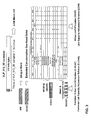
- Figure 1 is a functional diagram illustrative of a sequence of steps taken for mapping such a continuous packet flow into one or more E1 (2048 Kbit/s) PDH signals.
- the first of these containers is designated a VLP_512_4E container.
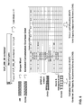
- VLP_512_4E container is comprised of 512 bytes repeated every 2 ms. That means that the VLP_512_4E container throughput is equal to 2,048 Mbit/s, which makes it possible to map this container into one unframed E1 signal. Within the VLP_512_4E container four bytes are reserved for special purposes as better detailed in figure 2 :
- the "Unique Word” represents a synchronization word, which permits to identify the VLP_512_4E container frame alignment.
- Concatenation Overhead Octet is the Concatenation Overhead Octet as described in ITU-T reference G.7043.
- VCAT and LCAS operations as described in ITU-T references G.7042 and G.7043 can be realized.
- the "Container Virtual Concatenation Octet” transports Multi Container Identifier (MC-ID) and container order information (C-ORDER) that are used to realize Container Virtual Concatenation (C-VCAT) as described in the following.
- MC-ID Multi Container Identifier
- C-ORDER container order information
- C-VCAT Container Virtual Concatenation
- the "Container Link Capacity Adjustment Octet” transports alarm and management bits that are used in order to realize Container Link Capacity Adjustment Scheme (C-LCAS) as described in the following.
- C-LCAS Container Link Capacity Adjustment Scheme
- VLP_512_2E container The second type of container considered herein is designated a VLP_512_2E container.
- the VLP_512_2E container is comprised of 512 bytes repeated every 2 ms. As is the case for the VLP_512_4E container discussed previously, the throughput for the VLP_512_2E container is equal to 2,048 Mbit/s, which again makes it possible to map this container onto one unframed E1 signal.
- VLP_512_2E Within the VLP_512_2E container two bytes are reserved for special purposes as depicted in figure 3 , i.e.:
- the "Unique Word” represents a synchronization word, which permits to identify the VLP_512_2E container frame alignment.
- the "Extended Concatenation Overhead Octet” is the Concatenation Overhead Octet as described in ITU-T reference G.7043 where some reserved bits are used in order to transport, by time division multiplexing technique, Container Virtual Concatenation Octet and Container Link Capacity Adjustment Octet information.
- VCAT and LCAS operations can be realized as described in ITU-T recommendations G.7042 and G.7043.
- Container Virtual Concatenation (C-VCAT) and Container Link Capacity Adjustment Scheme (C-LCAS) can be realized as better described in the following.
- VLP_512_4E and VLP_512_2E containers have throughputs equal to 2,048 Mbit/s and can be mapped onto one unframed E1 signal.
- VLPoverE1 In order to transport VLP over E1 signal (VLPoverE1) the continuous packet flow that carries the VLP packet flow is inserted in the payload bytes of the two containers, thus making it possible TO insert VLP traffic over PDH E1 signal.
- Some of the arrangements described in the co-pending application already referred to in the foregoing involve segmentation/fragmentation of the VLP packets. These segmentation operations and the reassembling operations associated therewith lead to some net throughput degradation in terms of Real Throughput (Throughput REAL ) in comparison with the Theoretical Throughput (Throughput THEO ) that can easily be calculated in both cases.
- Theoretical Throughput represents the payload throughput within VLP_512_xE.
- Figure 4 is a functional diagram illustrative of a sequence of steps taken for mapping the same continuous packet flow into one or more T1 (1544 Kbit/s) PDH signals.
- the first of these containers is designated a VLP_386_4E container.
- VLP_512_4E container is comprised of 386 bytes repeated every 2 ms. That means that VLP_386_4E container throughput is equal to 1,544 Mbit/s, therefore can be mapped onto one unframed T1 signal.
- the "Unique Word” represents a synchronization word, which permits to identify the VLP_386_4E container frame alignment.
- Concatenation Overhead Octet is the Concatenation Overhead Octet as described in ITU-T reference G.7043.
- VCAT and LCAS operations as described in ITU-T references G.7042 and G.7043 can be realized.
- the "Container Virtual Concatenation Octet” transports Multi Container Identifier (MC-ID) and container order information (C-ORDER) that is used to realize Container Virtual Concatenation (C-VCAT) as described in the following
- the "Container Link Capacity Adjustment Octet” transports alarm and management bits that are used in order to realize a Container Link Capacity Adjustment Scheme (C-LCAS) as described in the following.
- C-LCAS Container Link Capacity Adjustment Scheme
- VLP_386_2E container The second type of container considered herein is designated a VLP_386_2E container.
- VLP_386_2E container is comprised of 386 bytes repeated every 2 ms. As is the case with the VLP_386_4E container, the throughput of the VLP_386_2E container is equal to 1,544 Mbit/s. which makes it possible to map the VLP_386_2E container onto one unframed T1 signal. Again, within the VLP_386_2E container two bytes are reserved for special purposes as depicted in figure 6 :
- the "Unique Word” represents a synchronization word, which permits to identify the VLP_386_2E container frame alignment.
- the "Extended Concatenation Overhead Octet” is the Concatenation Overhead Octet as described in ITU-T reference G.7043 where some reserved bits are used in order to transport, by a time division multiplexing technique, Container Virtual Concatenation Octet and Container Link Capacity Adjustment Octet information.
- VCAT and LCAS operations can be realized as described in ITU-T recommendations G.7042 and G.7043.
- Container Virtual Concatenation (C-VCAT) and Container Link Capacity Adjustment Scheme (C-LCAS) can be realized as better described in the following.
- VLP_386_4E and VLP_386_2E containers have throughputs equal to 1,544 Mbit/s, so that they can be mapped onto one unframed T1 signal.
- VLPoverT1 In order to transport VLP over a T1 signal (VLPoverT1) the continuous packet flow that carries the VLP packet flow is inserted in the payload bytes of the two containers, thus making it possible TO insert VLP traffic over PDH T1 signal.
- VLPoverT1 the continuous packet flow that carries the VLP packet flow is inserted in the payload bytes of the two containers, thus making it possible TO insert VLP traffic over PDH T1 signal.
- Some of the arrangements described in the co-pending application already referred to in the foregoing involve segmentation/fragmentation of the VLP packets. These segmentation operations and the reassembling operations associated therewith lead to some net throughput degradation in terms of Real Throughput (Throughput REAL ) in comparison with the Theoretical Throughput (Throughput THEO ) that can easily be calculated in both cases.
- Theoretical Throughput represents the payload throughput within VLP_ VLP_386_xE.
- VLP-containers VLP-Containers
- VLP-Containers are generated with the same time reference.
- the Extended Concatenation Overhead Octet and Container Virtual Concatenation Octet are used in order to manage Container Virtual concatenation.
- VLP-Container synchronization and reordering i.e. reconstructing the original data flow bytes sequence
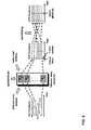
- these items of information permit delay compensation and reordering of the VLP-containers. This result is usually achieved by using different delay memories as schematically shown in figure 9 .
- AP Alignment Probability
- FMP False Misalignment Probability
- FAP False Alignment Probability
- a container Link Capacity Adjustment Scheme (C-LCAS) can be resorted to whenever an advantage may exist in being able to change Virtual Container Concatenation Capacity by stopping data transfer into one particular VLP-container.
- This approach can be used, for instance, in order to control data throughput in case of frequently and temporary local memory early overflow alarm inside circuits that perform F-GFP or FFP.
- This operation is schematically represented in the diagram of figure 11 and is referred to as "Container Capacity Adjustment Scheme", and further detailed in figure 12 .
- FIG. 12 details the exchange of messages between two network elements designated NetElement1 and NetElement2, respectively, during a Container Suspension Procedure (CSP)
- CSP Container Suspension Procedure
- FIG. 12 The right-hand portion of figure 12 details the exchange of messages between two network elements, again designated NetElement1 and NetElement2, respectively, during a Container Re-Admission Procedure (CRP)
- CCP Container Re-Admission Procedure
- the Container Link Capacity Adjustment Octet is used in order to manage Container Link Capacity Adjustment Scheme.
- the GFP Payload Area is variable length area that may include from 4 to 65535 octets. This means that packets of size up to 65535 bytes can be mapped into GFP packet. However, for the purposes of this description maximum packet size is not a mandatory requirement.
- the ITU-T V-CAT recommendation makes it possible to concatenate up to 16 PDH signals into the same Virtual Group.
- the C-VCAT strategy described herein makes possible concatenate up to 256 PDH flow.
- both the ITU-T recommendation and the C-VCAT strategy described herein permit to compensate differential delay values up to ⁇ 256 ms between PDH E1 signals.
- the ITU-T V-CAT is able to compensate up to ⁇ 384 ms
- the C-VCAT strategy is able to compensate up to ⁇ 256 ms of differential delay between PDH T1 signals.
Landscapes
- Engineering & Computer Science (AREA)
- Computer Hardware Design (AREA)
- Computer Networks & Wireless Communication (AREA)
- Signal Processing (AREA)
- Data Exchanges In Wide-Area Networks (AREA)
- Time-Division Multiplex Systems (AREA)
- Communication Control (AREA)
Abstract
Description
- The invention relates to techniques for transmitting data over Plesiochronous Digital Hierarchy (PDH) channels.
- Properly managing communication networks adapted to handle multi-standard traffic (i.e. hybrid network standards) is an ever increasing requirement and conventional technology-specific interface solutions become increasingly insufficient for that purpose.
- The ITU-T G.7041 Recommendation defines a Generic Framing Procedure (GFP) to delineate octet-aligned, variable-length payloads from higher-level client signals for subsequent mapping into octet synchronous paths. Mapping of such a GFP frame into PDH-type traffic forms the subject mater of the ITU-T G.8040 Recommendation.
- The generic framing procedure (GFP), as defined in ITU-T Rec. G.7041/Y.1303, was developed for transport of data clients over synchronous digital hierarchy (SDH) networks of ITU-T Rec. G.707/Y.1322 and optical transport networks (OTN) of ITU-T Rec. G.709/Y.1331. Interfaces from the plesiochronous digital hierarchy (PDH) are ubiquitous, especially in the access networks where there is a desire to carry client data signals. GFP has been identified as a suitable technique for mapping data frames into PDH signals of the hierarchies of ITU-T Rec. G.704 as well as the virtually concatenated PDH signals as defined in ITU-T Rec. G.7043/Y.1343.
- Recommendation ITU-T G.8040 provides for mapping of GFP-encapsulated data into PDH signals for transport over PDH trails. The octet-wise mapping into octet-oriented transport containers originally defined for GFP is maintained. When a GFP frame is to be mapped onto T1 signals, the 1544 kbit/s signal payload is typically arranged as 24 octets (i.e.,
time slots 1 to 24). The multiframe structure for the 24-frame multiframe as described in ITU-T Rec. G.704 is typically used. The first octet following the first framing bit of the multiframe is used to carry the concatenation overhead, as defined in ITU-T Rec. G.7043/Y.1343. This octet is reserved for all values of N, (N = 1...16). - When neither of the VCAT/LCAS arrangements to be discussed in the following is used (which implies one 1544 kbit/s signal), the concatenation overhead octet shall is set to a value of 0x00. When neither GFP client data frames nor GFP client management frames are available from the GFP source adaptation process, GFP Idle frames shall be inserted in order to perform rate adaptation, filling the server capacity as described in ITU-T Rec. G.7041/Y.1303. GFP frames are scrambled consistent with ITU-T Rec. G.7041/Y.1303. GFP frame delineation is performed in the manner described in ITU-T Rec. G.7041/Y.1303.
- Conversely, when a GFP frame is to be mapped onto E1 signals, the basic frame structure at 2048 kbit/s as described in ITU-T Rec. G.704 shall be used. Time slots 1-31 are used to carry the GFP octets. The multiframe structure for the 16-frame multiframe as described in ITU-T Rec. G.704 is be used.
Time slot 1 of the first frame of the multiframe is used to carry the concatenation overhead, as defined in ITU-T Rec. G.7043/Y.1343. This octet is reserved for all values of N, (N = 1...16). - For the non-VCAT/LCAS case (which implies one 2048 kbit/s signal), the concatenation overhead octet shall be set to a value of 0x00. When neither GFP client data frames nor GFP client management frames are available from the GFP source adaptation process, GFP Idle frames shall be inserted in order to perform rate adaptation, filling the server capacity as described in ITU-T Rec. G.7041/Y.1303. GFP frames are scrambled consistent with ITU-T Rec. G.7041/Y.1303. GFP frame delineation is performed in the manner described in ITU-T Rec. G.7041/Y.1303.
- Adopting the ITU-T strategy leads to the following throughput values:

where:
and
- Other recommendations such as ITU-T G.7042 and ITU-T G.7043 describe additional procedures known as Container - Link Capacity Adjustment Scheme (C-LCAS) and Container - Virtual conCATenation (C-VCAT), which can be used in the context referred to herein.
- In the case of Virtual concatenation (VCAT) of PDH signals (ITU-T G.7043), the basic PDH signal frame structures for 1544, 2048 and 44 736 kbit/s signals are defined in ITU-T Rec. G.704 and the octet structure 34 368 kbit/s is defined in ITU-T Rec. G.832. Recommendation G.7043 enhances the functions of these frame structures to support the virtual concatenation of these frame structures to form larger transport entities (containers). Only frame structures of the same type can be virtually concatenated together. This virtual concatenation supports the Link Capacity Adjustment Scheme (LCAS) specified in ITU-T Rec. G.7042/Y.1305. The concatenation overhead octet is time-multiplexed to carry the overhead required for virtual concatenation. This time multiplexing takes the form of a 16-nibble VLI (Very Long Instruction) that is transmitted one nibble per concatenation overhead octet. The concatenation overhead octet contains one nibble for the VLI and one nibble for the MFI1. The definitions of the fields within the control packet are given in ITU-T Rec. G.7042/Y.1305.
- In the case of Virtual concatenation (VCAT) of T1 signals, the multiframe structure for the 24-frame multiframe as described in ITU-T Rec. G.704 is used. The first octet following the first framing bit of the multiframe is used to carry the concatenation overhead for each 1544 kbit/s signal. This octet is reserved for all values of N (N = 1...16). The concatenation overhead octet allows the virtual concatenation of N 1544 kbit/s signals to form a single channel referred to as a virtual concatenation group (VCG). The payload container bandwidth of the resulting VCG is Nx[1536-(64/24)] kbit/s ≅ Nx1533 kbit/s. Client signals are mapped into the Nx1544 kbit/s signal members of the VCG on an octet-wise, round-robin basis. The round robin sequence follows the ascending order of the per-member sequence numbers that are communicated in each member's concatenation overhead octet. For example, if a data packet's
octet 1 is mapped into the 1544 kbit/s signal withsequence number 0, the next packet octet is mapped into the 1544 kbit/s signal withsequence number 1, etc. Up to sixteen 1544 kbit/s signals can be virtually concatenated into a single VCG. In general, the virtual concatenation and associated Link Capacity Adjustment Scheme (LCAS) functionality and definitions are the same as those specified for SDH virtual containers in ITU-T Rec. G.707/Y.1322. All Nx1544 kbit/s member signals that constitute a VCG are aligned at their transmission from the VCG source with respect to their 1544 kbit/s clock frequency, PDH signal frame and multiframe, MFI1 and MFI2. The VCG sink can determine the differential delay that the different members encountered in the network by comparing their respective MFI1 and MFI2 values, and performing the proper realignment. The four MSBs of MFI2 are not used for differential delay compensation. The maximum differential delay that can be detected is ± (256)(24)(125µs)/2 = ±384 ms. - In the case of Virtual concatenation (VCAT) of E1 signals, the basic frame and 16-frame multiframe structure at 2048 kbit/s as described in ITU-T Rec. G.704 shall be used. The
time slot 1 of the first frame of the multiframe is used to carry the concatenation overhead for each 2048 kbit/s signal. This octet is reserved for all values of N (N = 1...16). The concatenation overhead octet allows the virtual concatenation of N 2048 kbit/s signals to form a single channel referred to as a virtual concatenation group. The payload container bandwidth of the resulting VCG is Nx[1984-(64/16)] kbit/s = Nx1980 kbit/s. Client signals are mapped into the Nx2048 kbit/s signal members of the VCG on an octet-wise, round-robin basis. The round robin sequence follows the ascending order of the per-member sequence numbers that are communicated in each member's concatenation overhead octet. For example, if a data packet'soctet 1 is mapped into the 2048 kbit/s signal withsequence number 0, the next packet octet is mapped into the 2048 kbit/s signal withsequence number 1, etc. Up to sixteen 2048 kbit/s signals can be virtually concatenated into a single VCG. The concatenation octet definitions for the 2048 kbit/s signal are the same as those specified in the foregoing for T1 signals. Also the differential delay compensation for the 2048 kbit/s signal is the same, except that the clock frequency is 2048 kbit/s. The four MSBs of MFI2 are not used for differential delay compensation. The maximum differential delay that can be detected is ±(256)(16)(125µs)/2 = ±256 ms. - Recommendation ITU-T G. 7042 specifies a Link Capacity Adjustment Scheme (LCAS) for VCAT signals (ITU-T G.7042) for use in increasing or decreasing the capacity of a container that is transported in an SDH/OTN network using Virtual Concatenation. In addition, the scheme will automatically decrease the capacity if a member experiences a failure in the network and increase the capacity when the network fault is repaired. The scheme is applicable to every member of the Virtual Concatenation group. This Recommendation defines the required states at the source and at the sink side of the link as well as the control information exchanged between both the source and the sink side of the link to enable the flexible resizing of this Virtual Concatenated signal.
- LCAS in the virtual concatenation source and sink adaptation functions provides a control mechanism to hitless increase or decrease the capacity of a VCG link to meet the bandwidth needs of the application. Hitless bandwidth modification can only be achieved when the transmission of the active members belonging to the VCG - before and after the bandwidth modification - is error free. It also provides the capability of temporarily removing member links that have experienced a failure. The LCAS scheme assumes that in cases of capacity adjustment (i.e., creation, increase, decrease or deletion), the construction or destruction of the end-to-end path of each individual member is the responsibility of the Network and Element Management Systems. A VCG capacity increase or decrease can be initiated at either end.
- Synchronization of changes in the capacity of the transmitter (So) and the receiver (Sk) shall be achieved by a control packet. Each control packet describes the state of the link during the next control packet. Changes are sent in advance so that the receiver can switch to the new configuration as soon as it arrives.
- The control packet consists of fields dedicated to a specific function. The control packet contains information sent from So to Sk and information sent from Sk to So, i.e.:
- Forward direction, So to Sk:
- MultiFrame Indicator (MFI) field;
- Sequence Indicator (SQ) field;
- Control (CTRL) field;
- Group Identification (GID) bit.
- Return direction, Sk to So:
- Member Status (MST) field;
- Re-Sequence Acknowledge (RS-Ack) bit.
- The LCAS generally assumes directional independence of individual members of a virtually concatenated group. This implies connection asymmetry, i.e., the bandwidth of the forward transport is independent of the bandwidth of the return transport.
- A basic drawback of the arrangements described in the foregoing, when applied to networks required to handle hybrid network standards, lies in the inherent complexity of their control structure and the overhead inevitably associated thereto.
- A basic object of the invention is thus to provide an arrangement which may overcome such a drawback. A specific object of the invention is to provide an effective mechanism to adapt variable length packet (VLP) traffic to a PDH transport network (i.e. to provide a VLPoverE1 or VLPoverT1 transmission scheme). All this while preserving the possibility of implementing Container - Link Capacity Adjustment Scheme (C-LCAS) and /or Container - Virtual conCATenation (C-VCAT), preferably by resorting to improved arrangements over those described in the recommendations ITU-T G.7042 and ITU-T G.7043.
- According to the present invention, that object is achieved by means of a method having the features set forth in the claims that follow. The invention also relates to a corresponding system, a corresponding network as well as a corresponding computer program product, loadable in the memory of at least one computer and including software code portions for performing the steps of the method of the invention when the product is run on a computer. As used herein, reference to such a computer program product is intended to be equivalent to reference to a computer-readable medium containing instructions for controlling a computer system to coordinate the performance of the method of the invention. Reference to "at least one computer" is evidently intended to highlight the possibility for the present invention to be implemented in a distributed/ modular fashion.
- The claims are an integral part of the disclosure of the invention provided herein.
- A preferred embodiment of the arrangement described herein is thus a method of transmitting a data flow over at least one Plesiochronous Digital Hierarchy (PDH) channel, said at least one Plesiochronous Digital Hierarchy (PDH) channel including channel bytes for carrying alignment and alarm data, the method including the step of using at least a set of said channel bytes to carry a synchronization word and for carrying said data flow.
- The invention will now be described, by way of example only, with reference to the enclosed figures of drawing, wherein:
-
Figure 1 is representative of an arrangement for transporting a VLP input data flow over a E1 PDH channel; -
Figure 2 further details the container arrangement offigure 1 ; -
Figure 3 illustrates a variant of the container arrangement offigure 1 -
Figure 4 is representative of an arrangement for transporting a VLP input data flow over a T1 PDH channel; -
Figure 5 further details the container arrangement offigure 4 ; -
Figure 6 illustrates a variant of the container arrangement offigure 4 ; -
Figures 7 and8 are illustrative of Container Virtual concatenation procedures adapted for use within the context of the arrangement described herein; -
Figure 9 are illustrative of Virtual Container Concatenation resynchronization and reordering procedures adapted for use within the context of the arrangement described herein; -
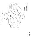
Figure 10 is illustrative of a frame alignment algorithm adapted for use within the context of the arrangement described herein; -
Figure 11 is illustrative of a Container Link Capacity Adjustment Scheme adapted for use within the context of the arrangement described herein; and -
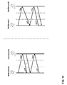
Figure 12 is further illustrative of the Container Link Capacity Adjustment Scheme as considered herein. - The following detailed description of exemplary embodiments will generally refer to transmitting over one or more E1 or T1 PDH channels a continuous packet flow obtained starting from a Variable Length Packet (VLP) input flow. One Variable Length Packet (VLP) signal, as Ethernet signal, can be transported over one or more PDH signals forming a Virtual Concatenated Containers Group (VCCG) by means of container aggregation.
- Preferably, such a VLP input flow has been mapped into the continuous packet flow in question by resorting to any of the methods described in a co-pending application filed on even date by the same applicant.
-
Figure 1 is a functional diagram illustrative of a sequence of steps taken for mapping such a continuous packet flow into one or more E1 (2048 Kbit/s) PDH signals. - In order to realize this mapping two specific containers are been defined.
- The first of these containers is designated a VLP_512_4E container.
- As shown in
figure 1 , such a VLP_512_4E container is comprised of 512 bytes repeated every 2 ms. That means that the VLP_512_4E container throughput is equal to 2,048 Mbit/s, which makes it possible to map this container into one unframed E1 signal. Within the VLP_512_4E container four bytes are reserved for special purposes as better detailed infigure 2 : - Unique Word (UW);
- Concatenation Overhead Octet (COO);
- Container Virtual Concatenation Octet (CVCO);
- Container Link Capacity Adjustment Octet (CLCAO).
- The "Unique Word" represents a synchronization word, which permits to identify the VLP_512_4E container frame alignment.
- The "Concatenation Overhead Octet" is the Concatenation Overhead Octet as described in ITU-T reference G.7043. By means of this byte VCAT and LCAS operations, as described in ITU-T references G.7042 and G.7043 can be realized.
- The "Container Virtual Concatenation Octet" transports Multi Container Identifier (MC-ID) and container order information (C-ORDER) that are used to realize Container Virtual Concatenation (C-VCAT) as described in the following.
- The "Container Link Capacity Adjustment Octet" transports alarm and management bits that are used in order to realize Container Link Capacity Adjustment Scheme (C-LCAS) as described in the following.
- The second type of container considered herein is designated a VLP_512_2E container.
- The VLP_512_2E container is comprised of 512 bytes repeated every 2 ms. As is the case for the VLP_512_4E container discussed previously, the throughput for the VLP_512_2E container is equal to 2,048 Mbit/s, which again makes it possible to map this container onto one unframed E1 signal.
- Within the VLP_512_2E container two bytes are reserved for special purposes as depicted in
figure 3 , i.e.: - Unique Word (UW);
- Extended Concatenation Overhead Octet (ECOO).
- Again, the "Unique Word" represents a synchronization word, which permits to identify the VLP_512_2E container frame alignment.
- The "Extended Concatenation Overhead Octet" is the Concatenation Overhead Octet as described in ITU-T reference G.7043 where some reserved bits are used in order to transport, by time division multiplexing technique, Container Virtual Concatenation Octet and Container Link Capacity Adjustment Octet information. By means of this byte VCAT and LCAS operations can be realized as described in ITU-T recommendations G.7042 and G.7043. Additionally, Container Virtual Concatenation (C-VCAT) and Container Link Capacity Adjustment Scheme (C-LCAS) can be realized as better described in the following.
- Both VLP_512_4E and VLP_512_2E containers have throughputs equal to 2,048 Mbit/s and can be mapped onto one unframed E1 signal.
- In order to transport VLP over E1 signal (VLPoverE1) the continuous packet flow that carries the VLP packet flow is inserted in the payload bytes of the two containers, thus making it possible TO insert VLP traffic over PDH E1 signal.
- Some of the arrangements described in the co-pending application already referred to in the foregoing involve segmentation/fragmentation of the VLP packets. These segmentation operations and the reassembling operations associated therewith lead to some net throughput degradation in terms of Real Throughput (Throughput REAL ) in comparison with the Theoretical Throughput (Throughput THEO ) that can easily be calculated in both cases. The Theoretical Throughput represents the payload throughput within VLP_512_xE.
-
Figure 4 is a functional diagram illustrative of a sequence of steps taken for mapping the same continuous packet flow into one or more T1 (1544 Kbit/s) PDH signals. - Again, in order to realize this mapping two specific containers are been defined.
- The first of these containers is designated a VLP_386_4E container.
- As shown in
figure 4 , such a VLP_512_4E container is comprised of 386 bytes repeated every 2 ms. That means that VLP_386_4E container throughput is equal to 1,544 Mbit/s, therefore can be mapped onto one unframed T1 signal. - Within the VLP_386_4E container, four bytes are reserved for special purposes as depicted in
figures 4 and5 : - Unique Word (UW);
- Concatenation Overhead Octet (COO);
- Container Virtual Concatenation Octet (CVCO);
- Container Link Capacity Adjustment Octet (CLCAO).
- The "Unique Word" represents a synchronization word, which permits to identify the VLP_386_4E container frame alignment.
- The "Concatenation Overhead Octet" is the Concatenation Overhead Octet as described in ITU-T reference G.7043. By means of this byte VCAT and LCAS operations, as described in ITU-T references G.7042 and G.7043 can be realized.
- The "Container Virtual Concatenation Octet" transports Multi Container Identifier (MC-ID) and container order information (C-ORDER) that is used to realize Container Virtual Concatenation (C-VCAT) as described in the following
- The "Container Link Capacity Adjustment Octet" transports alarm and management bits that are used in order to realize a Container Link Capacity Adjustment Scheme (C-LCAS) as described in the following.
- The second type of container considered herein is designated a VLP_386_2E container.
- VLP_386_2E container is comprised of 386 bytes repeated every 2 ms. As is the case with the VLP_386_4E container, the throughput of the VLP_386_2E container is equal to 1,544 Mbit/s. which makes it possible to map the VLP_386_2E container onto one unframed T1 signal. Again, within the VLP_386_2E container two bytes are reserved for special purposes as depicted in
figure 6 : - Unique Word (UW);
- Extended Concatenation Overhead Octet (ECOO).
- Again, the "Unique Word" represents a synchronization word, which permits to identify the VLP_386_2E container frame alignment.
- The "Extended Concatenation Overhead Octet" is the Concatenation Overhead Octet as described in ITU-T reference G.7043 where some reserved bits are used in order to transport, by a time division multiplexing technique, Container Virtual Concatenation Octet and Container Link Capacity Adjustment Octet information. By means of this byte VCAT and LCAS operations can be realized as described in ITU-T recommendations G.7042 and G.7043. Additionally, Container Virtual Concatenation (C-VCAT) and Container Link Capacity Adjustment Scheme (C-LCAS) can be realized as better described in the following.
- Both VLP_386_4E and VLP_386_2E containers have throughputs equal to 1,544 Mbit/s, so that they can be mapped onto one unframed T1 signal.
- In order to transport VLP over a T1 signal (VLPoverT1) the continuous packet flow that carries the VLP packet flow is inserted in the payload bytes of the two containers, thus making it possible TO insert VLP traffic over PDH T1 signal. Again, some of the arrangements described in the co-pending application already referred to in the foregoing involve segmentation/fragmentation of the VLP packets. These segmentation operations and the reassembling operations associated therewith lead to some net throughput degradation in terms of Real Throughput (Throughput REAL ) in comparison with the Theoretical Throughput (Throughput THEO ) that can easily be calculated in both cases. The Theoretical Throughput represents the payload throughput within VLP_ VLP_386_xE.
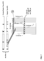
- When the VLP data throughput is greater than the throughput which can be carried by a single VLP-Container, a Virtual Container Concatenation structure is used. In this case, as schematically shown in
figure 7 , data flow bytes are subdivided into different VLP-Containers (VLP-containers). Since data flow bytes are inserted orthogonally into VLP-containers payload bytes, an increase in the number of the VLP-Containers used leads to a decrease in VLP transport delay. - In order to permit an orthogonal distribution of VLPs into VLP-Containers, the VLP-Containers are generated with the same time reference. The Extended Concatenation Overhead Octet and Container Virtual Concatenation Octet are used in order to manage Container Virtual concatenation.
- The extra information bytes carried within the containers permit VLP-Container synchronization and reordering (i.e. reconstructing the original data flow bytes sequence).
- Specifically:
- the Unique Word information, together with Frame Number information, enables re-synchronization of the containers;
- the Concatenation Overhead Octet information makes it possible to implement VCAT and LCAS as described in the ITU-T standard;
- the Container Virtual Concatenation Octet (CVCO) information makes it possible to implement Container Virtual conCATenation (C-VCAT) by transporting Virtual Container Concatenation Group and Virtual Container Concatenation Order information relative to the particular.
- the Container Link Capacity Adjustment Octet (CLCAO) makes it possible to implement Container Link Capacity Adjustment Scheme (C-LCAS) by transporting container adjustment messages.
- Upon reception of the VLP-Containers, these items of information permit delay compensation and reordering of the VLP-containers. This result is usually achieved by using different delay memories as schematically shown in
figure 9 . - Within the framework of a general VLP-Container alignment strategy the VLP-Container stream is continuously parsed searching for Unique Word (UW) information. As schematically shown in
figure 10 , once a UW is found and confirmed (for an elapsed time of R "Probably Aligned" frames, PA#), an "In Frame" state (IF) is reached. On the other hand, if a VLP-Container's UW is not found within an elapsed time of S "Probably Not Aligned" frames (PNA#) an "Out Of Frame" state (OOF) is declared. Once OOF frame is reached, R (PA#) confirmed frames are needed to reach back the IF state again. The OOF state, false detections and false un-detection might occur with different probabilities (where Pε is the bit error probability, p' is the digit probability (p'=0.5) and N is the number of bits in each frame). - Consequently, the Alignment Probability (AP), i.e. the probability of reaching the alignment state can be expressed as:

- Conversely, the False Misalignment Probability (FMP), i.e. the probability of loss of alignment state for a false un-detections due to error rate is given by:

- The False Alignment Probability (FAP), i.e. the probability of reaching the alignment state after false detections due to UW emulation is given by:

- A container Link Capacity Adjustment Scheme (C-LCAS) can be resorted to whenever an advantage may exist in being able to change Virtual Container Concatenation Capacity by stopping data transfer into one particular VLP-container.
- This approach can be used, for instance, in order to control data throughput in case of frequently and temporary local memory early overflow alarm inside circuits that perform F-GFP or FFP. This operation is schematically represented in the diagram of
figure 11 and is referred to as "Container Capacity Adjustment Scheme", and further detailed infigure 12 . - Specifically, the left-hand portion of
figure 12 details the exchange of messages between two network elements designated NetElement1 and NetElement2, respectively, during a Container Suspension Procedure (CSP) - The following designations apply:
- CSR = Container Suspension Request
- CSCD = Container Suspension CountDown
- CAA = Container Align Alarm
- CSA = Container Suspension Acknowledge.
- The right-hand portion of
figure 12 details the exchange of messages between two network elements, again designated NetElement1 and NetElement2, respectively, during a Container Re-Admission Procedure (CRP) - The following designations apply:
- CRR = Container Re-admission Request
- CRA = Container Re-admission Acknowledge
- CAO = Container Align OK
- CRCD = Container Re-admission CountDown.
- Various automatic procedures for VLP-container suspension and readmission can be implemented in order to standardize VLP-container level procedures to manage data throughput change. The Container Link Capacity Adjustment Octet is used in order to manage Container Link Capacity Adjustment Scheme. The GFP Payload Area is variable length area that may include from 4 to 65535 octets. This means that packets of size up to 65535 bytes can be mapped into GFP packet. However, for the purposes of this description maximum packet size is not a mandatory requirement.
- Concerning the maximum number of PDH signals per Virtual Group, the ITU-T V-CAT recommendation makes it possible to concatenate up to 16 PDH signals into the same Virtual Group. By way of contrast, the C-VCAT strategy described herein makes possible concatenate up to 256 PDH flow. As regards PDH signal resynchronization, both the ITU-T recommendation and the C-VCAT strategy described herein permit to compensate differential delay values up to ±256 ms between PDH E1 signals. Specifically, while the ITU-T V-CAT is able to compensate up to ±384 ms, the C-VCAT strategy is able to compensate up to ±256 ms of differential delay between PDH T1 signals.
- As regards Net throughput performance for each PDH signal, the applicant has conducted experimentation concerning both mapping onto PDH E1 and mapping onto PDH T1. Packets with average sizes of 64 and 256 bytes have been considered leading to thoroughly satisfactory performance.
- All the processing steps illustrated in the figures herein can be performed by resorting to a dedicated processor system or a general purpose processor system suitably programmed (according to criteria that are known per se) to perform those processing steps.
- Without prejudice to the underlying principles of the invention, the details and the embodiments may vary, even appreciably, with reference to what has been described by way of example only, without departing from the scope of the invention as defined by the annexed claims.
Claims (12)
- A method of transmitting a data flow over at least one Plesiochronous Digital Hierarchy (PDH) channel, said at least one Plesiochronous Digital Hierarchy (PDH) channel including channel bytes for carrying alignment and alarm data, the method including the step of using at least a set of said channel bytes to carry a synchronization word and for carrying said data flow.
- The method of claim 1, including the steps of arranging said data flow in data containers, each said container including one byte comprising a synchronization word to identify a frame alignment of said container.
- The method of claim 2, wherein each said container includes one concatenation overhead octet to permit ITU-T compliant virtual concatenation (VCAT) and link capacity adjustment (LCAS) operation.
- The method of either of claims 2 or 3, wherein each said container includes one container virtual concatenation octet to transport a multi container identifier and container order information to realize virtual concatenation of said containers.
- The method of any of claims 2 to 4, wherein each said container includes one container link capacity adjustment octet to transport alarm and management bits to perform link capacity adjustment of said containers.
- The method of claim 2 and claim 4, wherein each said container includes one ITU-T compliant extended concatenation overhead octet to transport said virtual concatenation octet.
- The method of claim 2 and claim 5, wherein each said container includes one ITU-T compliant extended concatenation overhead octet to transport said link capacity adjustment octet.
- The method of claim 6 and claim 7, wherein said extended concatenation overhead octet transports, by a time division multiplexing technique, both said virtual concatenation octet and said link capacity adjustment octet.
- The method of claim 2, wherein each said container is comprised of 512 bytes, with a throughput of 2,048 Mbit/s, whereby said containers can be mapped onto one unframed E1 PDH signal.
- The method of claim 2, wherein each said container is comprised of 386 bytes, with a throughput of 1,544 Mbit/s, whereby said containers can be mapped onto one unframed T1 PDH signal.
- A system for transmitting a data flow over at least one Plesiochronous Digital Hierarchy (PDH) channel, the system being configured to perform the method any of claims 1 to 10.
- A computer program product, directly loadable in the memory of at least one computer and including software code portions for performing the method of any of claims 1 to 10.
Priority Applications (3)
| Application Number | Priority Date | Filing Date | Title |
|---|---|---|---|
| EP07425441A EP2017989B1 (en) | 2007-07-18 | 2007-07-18 | A method and system for transmitting data over PDH channels |
| DE602007012077T DE602007012077D1 (en) | 2007-07-18 | 2007-07-18 | Method and system for data transmission via PDH channels |
| AT07425441T ATE496442T1 (en) | 2007-07-18 | 2007-07-18 | METHOD AND SYSTEM FOR DATA TRANSMISSION VIA PDH CHANNELS |
Applications Claiming Priority (1)
| Application Number | Priority Date | Filing Date | Title |
|---|---|---|---|
| EP07425441A EP2017989B1 (en) | 2007-07-18 | 2007-07-18 | A method and system for transmitting data over PDH channels |
Publications (2)
| Publication Number | Publication Date |
|---|---|
| EP2017989A1 true EP2017989A1 (en) | 2009-01-21 |
| EP2017989B1 EP2017989B1 (en) | 2011-01-19 |
Family
ID=38669629
Family Applications (1)
| Application Number | Title | Priority Date | Filing Date |
|---|---|---|---|
| EP07425441A Not-in-force EP2017989B1 (en) | 2007-07-18 | 2007-07-18 | A method and system for transmitting data over PDH channels |
Country Status (3)
| Country | Link |
|---|---|
| EP (1) | EP2017989B1 (en) |
| AT (1) | ATE496442T1 (en) |
| DE (1) | DE602007012077D1 (en) |
Cited By (1)
| Publication number | Priority date | Publication date | Assignee | Title |
|---|---|---|---|---|
| CN107528661A (en) * | 2016-06-22 | 2017-12-29 | 中兴通讯股份有限公司 | A kind of method and device of business processing |
-
2007
- 2007-07-18 AT AT07425441T patent/ATE496442T1/en not_active IP Right Cessation
- 2007-07-18 DE DE602007012077T patent/DE602007012077D1/en active Active
- 2007-07-18 EP EP07425441A patent/EP2017989B1/en not_active Not-in-force
Non-Patent Citations (4)
| Title |
|---|
| "Application Note 3849 - Ethernet-over-PDH Technology Overview", DALLAS SEMICONDUCTOR MAXIM, 30 May 2006 (2006-05-30), XP002459059, Retrieved from the Internet <URL:http://pdfserv.maxim-ic.com/en/an/AN3849.pdf> [retrieved on 20071116] * |
| "Generic framing procedure (GFP); G.7041/Y.1303 (08/05)", ITU-T STANDARD IN FORCE (I), INTERNATIONAL TELECOMMUNICATION UNION, GENEVA, CH, no. G7041/Y1303 8/5, 22 August 2005 (2005-08-22), XP017404569 * |
| "GFP frame mapping into Plesiochronous Digital Hierarchy (PDH); G.8040/Y.1340 (09/05)", ITU-T STANDARD IN FORCE (I), INTERNATIONAL TELECOMMUNICATION UNION, GENEVA, CH, no. G8040/Y1340 9/5, 6 September 2005 (2005-09-06), XP017404625 * |
| CHEN WENTAO ET AL.: "Performance Analysis of Two Ethernet over E1 Schemes", TSINGHUA SCI. TECH.; TSINGHUA SCIENCE AND TECHNOLOGY, vol. 12, no. 1, February 2007 (2007-02-01), State Key Laboratory on Microwave and Digital Communication Department of Electronic Engineering Tsinghua University, Beijing, 100084, China, pages 70 - 76, XP002458889, ISSN: 1007-0214 * |
Cited By (1)
| Publication number | Priority date | Publication date | Assignee | Title |
|---|---|---|---|---|
| CN107528661A (en) * | 2016-06-22 | 2017-12-29 | 中兴通讯股份有限公司 | A kind of method and device of business processing |
Also Published As
| Publication number | Publication date |
|---|---|
| DE602007012077D1 (en) | 2011-03-03 |
| ATE496442T1 (en) | 2011-02-15 |
| EP2017989B1 (en) | 2011-01-19 |
Similar Documents
| Publication | Publication Date | Title |
|---|---|---|
| US10237009B2 (en) | Dynamic hitless resizing in optical transport networks | |
| EP2037626A1 (en) | Bandwidth adjusting method in bod transaction and apparatus thereof | |
| EP0996246B1 (en) | Communication system | |
| US8166183B2 (en) | Method and system for fast virtual concatenation setup in a communication network | |
| EP1248420A2 (en) | Method and apparatus for mapping fast ethernet packets in SONET containers over a radio-link system | |
| WO2001097390A2 (en) | Transparent transport overhead mapping | |
| EP1574108B1 (en) | System, method and device for time slot status messaging among sonet nodes | |
| US20190052562A1 (en) | Method for processing data in ethernet, device, and system | |
| EP1339183B1 (en) | Method and device for transporting ethernet frames over a transport SDH/SONET network | |
| US20020018261A1 (en) | Transmission system | |
| EP2017989B1 (en) | A method and system for transmitting data over PDH channels | |
| EP1339198B1 (en) | Enhanced transport of ethernet traffic over a transport SDH/SONET network | |
| CN100496045C (en) | Method and system for supporting data framing protocol on multi-service transmission node equipment | |
| EP1926256B1 (en) | Method of time aligning the members of a virtual concatenated group in a synchronous transmission system | |
| EP1936849B1 (en) | Method for mapping and demapping data information over the members of a concatenated group | |
| US20030002530A1 (en) | Method and apparatus for obtaining a scalable and managed bandwidth for connections between asynchronous level and synchronous hierarchy level in a telecommunication network | |
| Carrasco | Ethernet over SONET/SDH GFP, VCAT and LCAS | |
| EP2048828A1 (en) | Method and systems for data transmission over packet networks, corresponding computer program product | |
| EP1638228B1 (en) | Method and apparatus for computing virtual concatenation group bandwidth data | |
| EP1598969A1 (en) | Optimized link capacity adjustment scheme | |
| Caballero | SDH Next Generation | |
| Guild | Next Generation Synchronous Digital Hierarchy |
Legal Events
| Date | Code | Title | Description |
|---|---|---|---|
| PUAI | Public reference made under article 153(3) epc to a published international application that has entered the european phase |
Free format text: ORIGINAL CODE: 0009012 |
|
| AK | Designated contracting states |
Kind code of ref document: A1 Designated state(s): AT BE BG CH CY CZ DE DK EE ES FI FR GB GR HU IE IS IT LI LT LU LV MC MT NL PL PT RO SE SI SK TR |
|
| AX | Request for extension of the european patent |
Extension state: AL BA HR MK RS |
|
| 17P | Request for examination filed |
Effective date: 20090721 |
|
| 17Q | First examination report despatched |
Effective date: 20090812 |
|
| AKX | Designation fees paid |
Designated state(s): AT BE BG CH CY CZ DE DK EE ES FI FR GB GR HU IE IS IT LI LT LU LV MC MT NL PL PT RO SE SI SK TR |
|
| RTI1 | Title (correction) |
Free format text: METHOD AND SYSTEM FOR TRANSMITTING DATA OVER PDH CHANNELS |
|
| GRAP | Despatch of communication of intention to grant a patent |
Free format text: ORIGINAL CODE: EPIDOSNIGR1 |
|
| RTI1 | Title (correction) |
Free format text: A METHOD AND SYSTEM FOR TRANSMITTING DATA OVER PDH CHANNELS |
|
| GRAS | Grant fee paid |
Free format text: ORIGINAL CODE: EPIDOSNIGR3 |
|
| GRAA | (expected) grant |
Free format text: ORIGINAL CODE: 0009210 |
|
| AK | Designated contracting states |
Kind code of ref document: B1 Designated state(s): AT BE BG CH CY CZ DE DK EE ES FI FR GB GR HU IE IS IT LI LT LU LV MC MT NL PL PT RO SE SI SK TR |
|
| REG | Reference to a national code |
Ref country code: GB Ref legal event code: FG4D |
|
| REG | Reference to a national code |
Ref country code: CH Ref legal event code: EP |
|
| REG | Reference to a national code |
Ref country code: IE Ref legal event code: FG4D |
|
| REF | Corresponds to: |
Ref document number: 602007012077 Country of ref document: DE Date of ref document: 20110303 Kind code of ref document: P |
|
| REG | Reference to a national code |
Ref country code: DE Ref legal event code: R096 Ref document number: 602007012077 Country of ref document: DE Effective date: 20110303 |
|
| REG | Reference to a national code |
Ref country code: NL Ref legal event code: VDEP Effective date: 20110119 |
|
| LTIE | Lt: invalidation of european patent or patent extension |
Effective date: 20110119 |
|
| PG25 | Lapsed in a contracting state [announced via postgrant information from national office to epo] |
Ref country code: ES Free format text: LAPSE BECAUSE OF FAILURE TO SUBMIT A TRANSLATION OF THE DESCRIPTION OR TO PAY THE FEE WITHIN THE PRESCRIBED TIME-LIMIT Effective date: 20110430 Ref country code: IS Free format text: LAPSE BECAUSE OF FAILURE TO SUBMIT A TRANSLATION OF THE DESCRIPTION OR TO PAY THE FEE WITHIN THE PRESCRIBED TIME-LIMIT Effective date: 20110519 Ref country code: GR Free format text: LAPSE BECAUSE OF FAILURE TO SUBMIT A TRANSLATION OF THE DESCRIPTION OR TO PAY THE FEE WITHIN THE PRESCRIBED TIME-LIMIT Effective date: 20110420 Ref country code: LT Free format text: LAPSE BECAUSE OF FAILURE TO SUBMIT A TRANSLATION OF THE DESCRIPTION OR TO PAY THE FEE WITHIN THE PRESCRIBED TIME-LIMIT Effective date: 20110119 Ref country code: LV Free format text: LAPSE BECAUSE OF FAILURE TO SUBMIT A TRANSLATION OF THE DESCRIPTION OR TO PAY THE FEE WITHIN THE PRESCRIBED TIME-LIMIT Effective date: 20110119 Ref country code: PT Free format text: LAPSE BECAUSE OF FAILURE TO SUBMIT A TRANSLATION OF THE DESCRIPTION OR TO PAY THE FEE WITHIN THE PRESCRIBED TIME-LIMIT Effective date: 20110519 Ref country code: SE Free format text: LAPSE BECAUSE OF FAILURE TO SUBMIT A TRANSLATION OF THE DESCRIPTION OR TO PAY THE FEE WITHIN THE PRESCRIBED TIME-LIMIT Effective date: 20110119 |
|
| PG25 | Lapsed in a contracting state [announced via postgrant information from national office to epo] |
Ref country code: PL Free format text: LAPSE BECAUSE OF FAILURE TO SUBMIT A TRANSLATION OF THE DESCRIPTION OR TO PAY THE FEE WITHIN THE PRESCRIBED TIME-LIMIT Effective date: 20110119 Ref country code: BE Free format text: LAPSE BECAUSE OF FAILURE TO SUBMIT A TRANSLATION OF THE DESCRIPTION OR TO PAY THE FEE WITHIN THE PRESCRIBED TIME-LIMIT Effective date: 20110119 Ref country code: SI Free format text: LAPSE BECAUSE OF FAILURE TO SUBMIT A TRANSLATION OF THE DESCRIPTION OR TO PAY THE FEE WITHIN THE PRESCRIBED TIME-LIMIT Effective date: 20110119 Ref country code: FI Free format text: LAPSE BECAUSE OF FAILURE TO SUBMIT A TRANSLATION OF THE DESCRIPTION OR TO PAY THE FEE WITHIN THE PRESCRIBED TIME-LIMIT Effective date: 20110119 Ref country code: AT Free format text: LAPSE BECAUSE OF FAILURE TO SUBMIT A TRANSLATION OF THE DESCRIPTION OR TO PAY THE FEE WITHIN THE PRESCRIBED TIME-LIMIT Effective date: 20110119 Ref country code: CY Free format text: LAPSE BECAUSE OF FAILURE TO SUBMIT A TRANSLATION OF THE DESCRIPTION OR TO PAY THE FEE WITHIN THE PRESCRIBED TIME-LIMIT Effective date: 20110119 Ref country code: NL Free format text: LAPSE BECAUSE OF FAILURE TO SUBMIT A TRANSLATION OF THE DESCRIPTION OR TO PAY THE FEE WITHIN THE PRESCRIBED TIME-LIMIT Effective date: 20110119 Ref country code: BG Free format text: LAPSE BECAUSE OF FAILURE TO SUBMIT A TRANSLATION OF THE DESCRIPTION OR TO PAY THE FEE WITHIN THE PRESCRIBED TIME-LIMIT Effective date: 20110419 |
|
| PG25 | Lapsed in a contracting state [announced via postgrant information from national office to epo] |
Ref country code: EE Free format text: LAPSE BECAUSE OF FAILURE TO SUBMIT A TRANSLATION OF THE DESCRIPTION OR TO PAY THE FEE WITHIN THE PRESCRIBED TIME-LIMIT Effective date: 20110119 Ref country code: DK Free format text: LAPSE BECAUSE OF FAILURE TO SUBMIT A TRANSLATION OF THE DESCRIPTION OR TO PAY THE FEE WITHIN THE PRESCRIBED TIME-LIMIT Effective date: 20110119 |
|
| PLBE | No opposition filed within time limit |
Free format text: ORIGINAL CODE: 0009261 |
|
| STAA | Information on the status of an ep patent application or granted ep patent |
Free format text: STATUS: NO OPPOSITION FILED WITHIN TIME LIMIT |
|
| PG25 | Lapsed in a contracting state [announced via postgrant information from national office to epo] |
Ref country code: SK Free format text: LAPSE BECAUSE OF FAILURE TO SUBMIT A TRANSLATION OF THE DESCRIPTION OR TO PAY THE FEE WITHIN THE PRESCRIBED TIME-LIMIT Effective date: 20110119 Ref country code: RO Free format text: LAPSE BECAUSE OF FAILURE TO SUBMIT A TRANSLATION OF THE DESCRIPTION OR TO PAY THE FEE WITHIN THE PRESCRIBED TIME-LIMIT Effective date: 20110119 Ref country code: CZ Free format text: LAPSE BECAUSE OF FAILURE TO SUBMIT A TRANSLATION OF THE DESCRIPTION OR TO PAY THE FEE WITHIN THE PRESCRIBED TIME-LIMIT Effective date: 20110119 |
|
| 26N | No opposition filed |
Effective date: 20111020 |
|
| PG25 | Lapsed in a contracting state [announced via postgrant information from national office to epo] |
Ref country code: MT Free format text: LAPSE BECAUSE OF FAILURE TO SUBMIT A TRANSLATION OF THE DESCRIPTION OR TO PAY THE FEE WITHIN THE PRESCRIBED TIME-LIMIT Effective date: 20110119 Ref country code: IT Free format text: LAPSE BECAUSE OF FAILURE TO SUBMIT A TRANSLATION OF THE DESCRIPTION OR TO PAY THE FEE WITHIN THE PRESCRIBED TIME-LIMIT Effective date: 20110119 |
|
| REG | Reference to a national code |
Ref country code: DE Ref legal event code: R097 Ref document number: 602007012077 Country of ref document: DE Effective date: 20111020 |
|
| PG25 | Lapsed in a contracting state [announced via postgrant information from national office to epo] |
Ref country code: MC Free format text: LAPSE BECAUSE OF NON-PAYMENT OF DUE FEES Effective date: 20110731 |
|
| REG | Reference to a national code |
Ref country code: CH Ref legal event code: PL |
|
| REG | Reference to a national code |
Ref country code: IE Ref legal event code: MM4A |
|
| PG25 | Lapsed in a contracting state [announced via postgrant information from national office to epo] |
Ref country code: CH Free format text: LAPSE BECAUSE OF NON-PAYMENT OF DUE FEES Effective date: 20110731 Ref country code: LI Free format text: LAPSE BECAUSE OF NON-PAYMENT OF DUE FEES Effective date: 20110731 |
|
| PG25 | Lapsed in a contracting state [announced via postgrant information from national office to epo] |
Ref country code: IE Free format text: LAPSE BECAUSE OF NON-PAYMENT OF DUE FEES Effective date: 20110718 |
|
| REG | Reference to a national code |
Ref country code: GB Ref legal event code: 732E Free format text: REGISTERED BETWEEN 20120719 AND 20120725 |
|
| REG | Reference to a national code |
Ref country code: AT Ref legal event code: MK05 Ref document number: 496442 Country of ref document: AT Kind code of ref document: T Effective date: 20110119 |
|
| REG | Reference to a national code |
Ref country code: DE Ref legal event code: R081 Ref document number: 602007012077 Country of ref document: DE Owner name: DRAGONWAVE S.A R.L., LU Free format text: FORMER OWNER: NOKIA SIEMENS NETWORKS S.P.A., MILANO, IT Effective date: 20120731 Ref country code: DE Ref legal event code: R081 Ref document number: 602007012077 Country of ref document: DE Owner name: NOKIA SIEMENS NETWORKS ITALIA S.P.A., IT Free format text: FORMER OWNER: NOKIA SIEMENS NETWORKS S.P.A., MILANO, IT Effective date: 20120731 |
|
| PG25 | Lapsed in a contracting state [announced via postgrant information from national office to epo] |
Ref country code: LU Free format text: LAPSE BECAUSE OF NON-PAYMENT OF DUE FEES Effective date: 20110718 |
|
| REG | Reference to a national code |
Ref country code: FR Ref legal event code: CD Owner name: NOKIA SIEMENS NETWORKS ITALIA S.P.A., IT Effective date: 20130426 Ref country code: FR Ref legal event code: CA Effective date: 20130426 |
|
| REG | Reference to a national code |
Ref country code: FR Ref legal event code: CA Effective date: 20130607 Ref country code: FR Ref legal event code: TP Owner name: NOKIA SIEMENS NETWORKS ITALIA S.P.A., IT Effective date: 20130607 |
|
| PG25 | Lapsed in a contracting state [announced via postgrant information from national office to epo] |
Ref country code: TR Free format text: LAPSE BECAUSE OF FAILURE TO SUBMIT A TRANSLATION OF THE DESCRIPTION OR TO PAY THE FEE WITHIN THE PRESCRIBED TIME-LIMIT Effective date: 20110119 |
|
| PG25 | Lapsed in a contracting state [announced via postgrant information from national office to epo] |
Ref country code: HU Free format text: LAPSE BECAUSE OF FAILURE TO SUBMIT A TRANSLATION OF THE DESCRIPTION OR TO PAY THE FEE WITHIN THE PRESCRIBED TIME-LIMIT Effective date: 20110119 |
|
| REG | Reference to a national code |
Ref country code: FR Ref legal event code: PLFP Year of fee payment: 9 |
|
| PGFP | Annual fee paid to national office [announced via postgrant information from national office to epo] |
Ref country code: FR Payment date: 20150629 Year of fee payment: 9 |
|
| PG25 | Lapsed in a contracting state [announced via postgrant information from national office to epo] |
Ref country code: FR Free format text: LAPSE BECAUSE OF NON-PAYMENT OF DUE FEES Effective date: 20160801 |
|
| REG | Reference to a national code |
Ref country code: FR Ref legal event code: ST Effective date: 20170331 |
|
| REG | Reference to a national code |
Ref country code: DE Ref legal event code: R081 Ref document number: 602007012077 Country of ref document: DE Owner name: DRAGONWAVE S.A R.L., LU Free format text: FORMER OWNER: NOKIA SIEMENS NETWORKS ITALIA S.P.A., CASSINA DE PECCHI, IT |
|
| PGFP | Annual fee paid to national office [announced via postgrant information from national office to epo] |
Ref country code: DE Payment date: 20170724 Year of fee payment: 11 Ref country code: GB Payment date: 20170719 Year of fee payment: 11 |
|
| REG | Reference to a national code |
Ref country code: DE Ref legal event code: R119 Ref document number: 602007012077 Country of ref document: DE |
|
| GBPC | Gb: european patent ceased through non-payment of renewal fee |
Effective date: 20180718 |
|
| PG25 | Lapsed in a contracting state [announced via postgrant information from national office to epo] |
Ref country code: GB Free format text: LAPSE BECAUSE OF NON-PAYMENT OF DUE FEES Effective date: 20180718 Ref country code: DE Free format text: LAPSE BECAUSE OF NON-PAYMENT OF DUE FEES Effective date: 20190201 |