EP2017988A1 - A method and system for transmitting data over PDH channels and corresponding computer program product - Google Patents
A method and system for transmitting data over PDH channels and corresponding computer program product Download PDFInfo
- Publication number
- EP2017988A1 EP2017988A1 EP07425440A EP07425440A EP2017988A1 EP 2017988 A1 EP2017988 A1 EP 2017988A1 EP 07425440 A EP07425440 A EP 07425440A EP 07425440 A EP07425440 A EP 07425440A EP 2017988 A1 EP2017988 A1 EP 2017988A1
- Authority
- EP
- European Patent Office
- Prior art keywords
- packet
- byte
- packet flow
- flow
- bit
- Prior art date
- Legal status (The legal status is an assumption and is not a legal conclusion. Google has not performed a legal analysis and makes no representation as to the accuracy of the status listed.)
- Granted
Links
- 238000000034 method Methods 0.000 title claims description 35
- 238000004590 computer program Methods 0.000 title claims description 4
- 238000000638 solvent extraction Methods 0.000 claims abstract description 18
- 230000005540 biological transmission Effects 0.000 claims abstract description 7
- 238000013467 fragmentation Methods 0.000 claims description 9
- 238000006062 fragmentation reaction Methods 0.000 claims description 9
- 230000007246 mechanism Effects 0.000 claims description 8
- 238000012937 correction Methods 0.000 claims description 6
- 238000013507 mapping Methods 0.000 claims description 6
- 230000000295 complement effect Effects 0.000 claims description 2
- 125000004122 cyclic group Chemical group 0.000 claims description 2
- ZJPGOXWRFNKIQL-JYJNAYRXSA-N Phe-Pro-Pro Chemical compound C([C@H](N)C(=O)N1[C@@H](CCC1)C(=O)N1[C@@H](CCC1)C(O)=O)C1=CC=CC=C1 ZJPGOXWRFNKIQL-JYJNAYRXSA-N 0.000 claims 1
- 238000001514 detection method Methods 0.000 claims 1
- 238000012545 processing Methods 0.000 description 4
- 230000006978 adaptation Effects 0.000 description 3
- 238000013459 approach Methods 0.000 description 3
- 238000009432 framing Methods 0.000 description 3
- 238000003780 insertion Methods 0.000 description 3
- 230000037431 insertion Effects 0.000 description 3
- 230000011218 segmentation Effects 0.000 description 3
- 230000001360 synchronised effect Effects 0.000 description 2
- 230000001131 transforming effect Effects 0.000 description 2
- 239000006163 transport media Substances 0.000 description 2
- 230000002411 adverse Effects 0.000 description 1
- 230000002776 aggregation Effects 0.000 description 1
- 238000004220 aggregation Methods 0.000 description 1
- 238000004364 calculation method Methods 0.000 description 1
- 230000015556 catabolic process Effects 0.000 description 1
- 238000004891 communication Methods 0.000 description 1
- 238000006731 degradation reaction Methods 0.000 description 1
- 238000010586 diagram Methods 0.000 description 1
- 230000000694 effects Effects 0.000 description 1
- 238000005516 engineering process Methods 0.000 description 1
- 239000000945 filler Substances 0.000 description 1
- 239000012634 fragment Substances 0.000 description 1
- 230000006870 function Effects 0.000 description 1
- 230000000977 initiatory effect Effects 0.000 description 1
- 239000002609 medium Substances 0.000 description 1
- 230000003362 replicative effect Effects 0.000 description 1
- 238000000926 separation method Methods 0.000 description 1
- 230000007723 transport mechanism Effects 0.000 description 1
- VLCQZHSMCYCDJL-UHFFFAOYSA-N tribenuron methyl Chemical compound COC(=O)C1=CC=CC=C1S(=O)(=O)NC(=O)N(C)C1=NC(C)=NC(OC)=N1 VLCQZHSMCYCDJL-UHFFFAOYSA-N 0.000 description 1
Images


Classifications
-
- H—ELECTRICITY
- H04—ELECTRIC COMMUNICATION TECHNIQUE
- H04J—MULTIPLEX COMMUNICATION
- H04J3/00—Time-division multiplex systems
- H04J3/02—Details
- H04J3/06—Synchronising arrangements
- H04J3/062—Synchronisation of signals having the same nominal but fluctuating bit rates, e.g. using buffers
- H04J3/0626—Synchronisation of signals having the same nominal but fluctuating bit rates, e.g. using buffers plesiochronous multiplexing systems, e.g. plesiochronous digital hierarchy [PDH], jitter attenuators
- H04J3/0629—Synchronisation of signals having the same nominal but fluctuating bit rates, e.g. using buffers plesiochronous multiplexing systems, e.g. plesiochronous digital hierarchy [PDH], jitter attenuators in a network, e.g. in combination with switching or multiplexing, slip buffers
Definitions
- the invention relates to techniques for transmitting data over Plesiochronous Digital Hierarchy (PDH) channels.
- PDH Plesiochronous Digital Hierarchy
- VLPoverPDH provides a generic mechanism to adapt variable length packet (VLP) traffic to a PDH transport network.
- VLP signals need be mapped onto the different Plesiochronous Digital Hierarchy (PDH) signals.
- the ITU-T G.7041 Recommendation defines a Generic Framing Procedure (GFP) to delineate octet-aligned, variable-length payloads from higher-level client signals for subsequent mapping into octet synchronous paths.
- GFP Generic Framing Procedure
- the definitions provided in the Recommendation include the frame formats for protocol data units (PDUs) transferred between GFP initiation and termination points, and the mapping procedure for the client signals into GFP.
- PDUs protocol data units
- GFP client frames and GFP control frames; frame formats for GFP client and control frames are defined.
- GFP also supports a flexible (payload) header extension mechanism to facilitate the adaptation of GFP for use with diverse transport mechanisms.
- payload extension header types are specified.
- the basic signal structure for GFP client frames provides for GFP frames that are octet-aligned and consist of a GFP Core Header and, except for GFP Idle frames, a GFP Payload Area.
- the four octets of the GFP Core Header consist of a 16-bit Payload Length Indicator field and a 16-bit Core Header Error Check (cHEC) field. This header allows GFP frame delineation independent of the content of the higher layer PDUs.
- the GFP Payload Area which is comprised of all the octets in the GFP frame after the GFP Core Header, is used to convey higher layer specific protocol information. This variable length area may include from 4 to 65535 octets.
- the GFP Payload Area consists of two common components: a Payload Header and a Payload Information field. An optional Payload FCS (pFCS) field is also supported.
- the Payload Header is a variable-length area, 4 to 64 octets long, intended to support data link management procedures specific to the higher-layer client signal.
- the structure of the GFP Payload Header provides for an area containing two mandatory fields, the Type and the tHEC fields, and a variable number of additional payload header fields. This group of additional payload header fields is referred to as the Extension Header.
- the presence of the Extension Header, and its format, and the presence of the optional Payload FCS are specified by the Type field.
- the tHEC protects the integrity of the Type field.
- the Payload Information field contains the framed PDU for frame mapped GFP or, in the case of transparent GFP, a group of client signal characters.
- This variable length field may include from 0 to 65535-X octets, where X is the size of the Payload Header.
- This field may include an optional Payload FCS field.
- the client PDU/signal is always transferred into the GFP Payload Information field as an octet-aligned packet stream.
- Scrambling of the GFP Payload Area is required to provide security against payload information replicating scrambling word (or its inverse) from a frame synchronous scrambler such as those used in the SDH RS layer or in an OTN OPUk channel. All octets in the GFP Payload Area are scrambled using a 1 + x 43 self-synchronous scrambler. Scrambling is done in network bit order.
- GFP control frames are used in the management of the GFP connection.
- the only control frame specified at this time is the GFP Idle frame.
- the GFP Idle frame is a special four-octet GFP control frame consisting of only a GFP Core Header with the PLI and cHEC fields (see 6.1.1) set to 0, and no Payload Area.
- the Idle frame is intended for use as a filler frame for the GFP source adaptation process to facilitate the adaptation of the GFP octet stream to any given transport medium where the transport medium channel has a higher capacity than required by the client signal.
- the object of the invention is thus to provide an arrangement which may overcome such a drawback.
- the invention also relates to a corresponding system, a corresponding network as well as a corresponding computer program product, loadable in the memory of at least one computer and including software code portions for performing the steps of the method of the invention when the product is run on a computer.
- a computer program product is intended to be equivalent to reference to a computer-readable medium containing instructions for controlling a computer system to coordinate the performance of the method of the invention.
- Reference to "at least one computer” is evidently intended to highlight the possibility for the present invention to be implemented in a distributed/ modular fashion.
- a preferred embodiment of the arrangement described herein is thus a method of transmitting a Variable Length Packet (VLP) input data flow over a Plesiochronous Digital Hierarchy (PDH) channel, including the step of mapping said Variable Length Packet input data flow into a continuous packet flow for transmission over the Plesiochronous Digital Hierarchy channel; the continuous packet flow includes subsequent partitioning bit strings wherein at least one bit string in a pair of subsequent partitioning bit strings is indicative of the length of an associated packet in the continuous packet flow; the method includes the step of inserting in the continuous packet flow a safeguard signal for said partitioning bit strings.
- VLP Variable Length Packet
- PDH Plesiochronous Digital Hierarchy
- the partitioning bit strings are in the form of pointers that indicate the length of an associated packet in the continuous packet flow by pointing to a "next" pointer associated to a subsequent packet in the flow.
- the safeguard signal is a frame period signal that permits re-synchronizing the continuous packet flow in case the partitioning strings/pointers are not properly detected.
- the partitioning bit strings are in the form of a unique word (UW) that marks the beginning (or the end) of an associated packet in the continuous packet flow, so that the length of an associated packet is indicated by the distance separating two subsequent unique words in the continuous packet flow.
- the safeguard signal may be a bit-long or byte-long signal inserted in the continuous packet flow whenever a bit string is detected in the continuous packet flow which "emulates” a unique word, so that such an "emulating" bit string cannot be erroneously taken as a unique word that marks the beginning of an associated packet.
- FIG. 1 is a functional diagram illustrative of a sequence of steps taken for mapping a Variable Length Packet (VLP) signal into a specific framing adapted for transporting the Variable Length Packet signal, as an Ethernet signal over one or more PDH signals forming e.g. a Virtual Concatenated Containers Group (VCCG) by means of container aggregation.
- VLP Variable Length Packet
- VCCG Virtual Concatenated Containers Group
- each packet in the Variable Length Packet input flow (which packet is usually comprised of a VLP header and a VLP payload) is subdivided into VLP Fragments (VLP-frag) of maximum size equal to e.g. 1024 bytes, forming what is designated in figure 1 a flow of Simple Packets (SPs).
- VLP-frag VLP Fragments
- VLP packets having a length in excess of the fragmentation threshold e.g. 1024 bytes
- VLP packets that are "shorter" than the fragmentation threshold are not fragmented and are passed on directly in the flow of Simple Packets (SPs).
- SPs Simple Packets
- a bit string in the form of a preamble such as a two byte preamble, designated a First/Next Packet Pointer (NPP) is added in order to obtain an Extended Packet (EP).
- NPP First/Next Packet Pointer
- EP Extended Packet
- CRC Cyclic Redundancy Code
- the Extended Packets EP are linked up to form an Extended Packet Sequence (EPS) and finally the Extended Packet Sequence is mapped into a Framed Packet Flow (FPF) frame with a length equal to 1024 bytes.
- EPS Extended Packet Sequence
- FPF Framed Packet Flow
- a "hole”, i.e. a discontinuity is present in the Extended Packet Sequence one (or more) idle packets are inserted in the Extended Packet Sequence to ensure continuity of the final Framed Packet Flow, i.e. to ensure that the final Framed Packet Flow is exempt from discontinuities.
- the idle packet length is typically 2 to 1024 byte (i.e. the fragmentation threshold).
- the Framed Packet Flow (FPF) frame is typically comprised of "Unique Words" (UWs) i.e. synchronization/framing bits that act as a safeguard signal for the Next Packet Pointer structure, by causing each Unique Word in the Framed Packet Flow (FPF) to be followed by a "first" Next Packet Pointer - indicated simply as a First Packet Pointer (FPP) in the drawing.
- UWs Unique Words
- FPP First Packet Pointer
- Each unique word UW (see figure 3 ) included in the FPF frame arrangement will in fact re-set that mechanism by making sure that the first packet pointer occurring in the Framed Packet Flow after a unique word UW will be used as a First Packet Pointer (FPP) to re-start the pointer mechanism, which will be thus safeguarded against errors.
- FPP/NPP fields are arranged as shown in figure 3 .
- the FPP bit string is comprised of a "BYTE_POINTER" field that indicates the first NPP byte after the associated packet and a "CODE” field (6 bits) that contains the error correction code, e.g. a Hamming (16,10,6) code.
- the first 10 bits in the NPP bit string indicate the size SP "SIZE” (i.e. again an indication of the length) of the subsequent associated packet.
- a "LAST” bit is then typically provided in the NPPs to indicate if the associated packet is part of a bigger packet that has been split (fragmented).
- a "CODE” field is provided containing a linear block code as an error correction code for the previous bits.
- a combination of a (15, 11) Hamming code proper and 5 parity bits is used which e.g.
- the exemplary FPF frame illustrated in the drawings is thus comprised of 1024 bytes: the first byte is the unique word (UW) byte, added for safeguard/synchronization purposes, while the second and third bytes form the so called First Packet Pointer (FPP) and are used to indicate the first byte in the frame that accommodate one NPP.
- UW unique word
- FPP First Packet Pointer
- This arrangement provides a give a simple way of finding Extended Packets (EPs) within the frame.
- EPs Extended Packets
- the frame structure just described makes it possible to safeguard the EPS alignment when a NPP is received corrupted.
- the introduction of an error correction code within the NPP and FPP minimizes EP alignment loss inside FPF frame.
- Figures 4 to 7 in the drawing are representative of an alternative approach based on flag separation of packets. This approach may in turn rely on two different solutions (bit processing or byte processing) to provide a safeguard signal.
- SP-Flag Simple Packet Flag
- the SP-Flag includes again a "Unique Word” (UW) plus a “Distinguish” bit and a “LAST” bit.
- the Extended Packets thus formed are linked to form a Packet Flow (PF). Again, if a "hole", i.e. a discontinuity, is present in the Extended Packet Sequence one (or more) idle packets are inserted in the Extended Packet Sequence so that the resulting Packet Flow is exempt from discontinuities.
- PF Packet Flow
- the SP-Flag field is configured as illustrated in figure 5 .
- the first 10 bits reproduce the Unique Word, then the Distinguish bit is inserted and finally there is a "LAST" bit to indicate if te packet is part of a bigger packet that has been split up.
- a byte stuffing technique is used to avoid idle flags into the Extended Packet stream.
- the CRC-16 value is calculated over the data bytes before the stuffing process. So, the byte stuffing is performed without effects over the CRC-16 value.
- the initial value is set to 0xFFFF and the polynomial X 16 + X 12 + X 5 + X 0 is used to calculate the final result. This value is inverted (logical "NOT") and inserted after the packet data with MSB sent first.
- the Extended Packets are then linked to form the output Packet Flow (PF) to be used for transmission.
- PF Packet Flow
- the GFP Payload Area is a variable length area that may include from 4 to 65535 octets. This means that packets of size up to 65535 bytes can be mapped into GFP packets as described herein.
Landscapes
- Engineering & Computer Science (AREA)
- Computer Hardware Design (AREA)
- Computer Networks & Wireless Communication (AREA)
- Signal Processing (AREA)
- Data Exchanges In Wide-Area Networks (AREA)
- Communication Control (AREA)
Abstract
Description
- The invention relates to techniques for transmitting data over Plesiochronous Digital Hierarchy (PDH) channels.
- Properly managing communication networks adapted to handle multi-standard traffic (i.e. hybrid network standards) is an ever increasing requirement and conventional technology-specific interface solutions become increasingly insufficient for that purpose. VLPoverPDH provides a generic mechanism to adapt variable length packet (VLP) traffic to a PDH transport network. For that purpose VLP signals need be mapped onto the different Plesiochronous Digital Hierarchy (PDH) signals.
- The ITU-T G.7041 Recommendation defines a Generic Framing Procedure (GFP) to delineate octet-aligned, variable-length payloads from higher-level client signals for subsequent mapping into octet synchronous paths. The definitions provided in the Recommendation include the frame formats for protocol data units (PDUs) transferred between GFP initiation and termination points, and the mapping procedure for the client signals into GFP.
- Specifically, two kinds of GFP frames are defined: GFP client frames and GFP control frames; frame formats for GFP client and control frames are defined. GFP also supports a flexible (payload) header extension mechanism to facilitate the adaptation of GFP for use with diverse transport mechanisms. Various payload extension header types are specified.
- The basic signal structure for GFP client frames provides for GFP frames that are octet-aligned and consist of a GFP Core Header and, except for GFP Idle frames, a GFP Payload Area. The four octets of the GFP Core Header consist of a 16-bit Payload Length Indicator field and a 16-bit Core Header Error Check (cHEC) field. This header allows GFP frame delineation independent of the content of the higher layer PDUs.
- The GFP Payload Area, which is comprised of all the octets in the GFP frame after the GFP Core Header, is used to convey higher layer specific protocol information. This variable length area may include from 4 to 65535 octets. The GFP Payload Area consists of two common components: a Payload Header and a Payload Information field. An optional Payload FCS (pFCS) field is also supported. The Payload Header is a variable-length area, 4 to 64 octets long, intended to support data link management procedures specific to the higher-layer client signal.
- The structure of the GFP Payload Header provides for an area containing two mandatory fields, the Type and the tHEC fields, and a variable number of additional payload header fields. This group of additional payload header fields is referred to as the Extension Header. The presence of the Extension Header, and its format, and the presence of the optional Payload FCS are specified by the Type field. The tHEC protects the integrity of the Type field.
- The Payload Information field contains the framed PDU for frame mapped GFP or, in the case of transparent GFP, a group of client signal characters. This variable length field may include from 0 to 65535-X octets, where X is the size of the Payload Header. This field may include an optional Payload FCS field. The client PDU/signal is always transferred into the GFP Payload Information field as an octet-aligned packet stream.
- Scrambling of the GFP Payload Area is required to provide security against payload information replicating scrambling word (or its inverse) from a frame synchronous scrambler such as those used in the SDH RS layer or in an OTN OPUk channel. All octets in the GFP Payload Area are scrambled using a 1 + x43 self-synchronous scrambler. Scrambling is done in network bit order.
- GFP control frames are used in the management of the GFP connection. The only control frame specified at this time is the GFP Idle frame. The GFP Idle frame is a special four-octet GFP control frame consisting of only a GFP Core Header with the PLI and cHEC fields (see 6.1.1) set to 0, and no Payload Area. The Idle frame is intended for use as a filler frame for the GFP source adaptation process to facilitate the adaptation of the GFP octet stream to any given transport medium where the transport medium channel has a higher capacity than required by the client signal.
- A basic drawback of the arrangement described in the foregoing, when applied to networks required to handle lies in the inherent complexity of its control (i.e. header) structure.
- The object of the invention is thus to provide an arrangement which may overcome such a drawback.
- According to the present invention, that object is achieved by means of a method having the features set forth in the claims that follow. The invention also relates to a corresponding system, a corresponding network as well as a corresponding computer program product, loadable in the memory of at least one computer and including software code portions for performing the steps of the method of the invention when the product is run on a computer. As used herein, reference to such a computer program product is intended to be equivalent to reference to a computer-readable medium containing instructions for controlling a computer system to coordinate the performance of the method of the invention. Reference to "at least one computer" is evidently intended to highlight the possibility for the present invention to be implemented in a distributed/ modular fashion.
- The claims are an integral part of the disclosure of the invention provided herein.
- A preferred embodiment of the arrangement described herein is thus a method of transmitting a Variable Length Packet (VLP) input data flow over a Plesiochronous Digital Hierarchy (PDH) channel, including the step of mapping said Variable Length Packet input data flow into a continuous packet flow for transmission over the Plesiochronous Digital Hierarchy channel; the continuous packet flow includes subsequent partitioning bit strings wherein at least one bit string in a pair of subsequent partitioning bit strings is indicative of the length of an associated packet in the continuous packet flow; the method includes the step of inserting in the continuous packet flow a safeguard signal for said partitioning bit strings.
- In an embodiment, the partitioning bit strings are in the form of pointers that indicate the length of an associated packet in the continuous packet flow by pointing to a "next" pointer associated to a subsequent packet in the flow. In this case, the safeguard signal is a frame period signal that permits re-synchronizing the continuous packet flow in case the partitioning strings/pointers are not properly detected.
- In an alternative embodiment, the partitioning bit strings are in the form of a unique word (UW) that marks the beginning (or the end) of an associated packet in the continuous packet flow, so that the length of an associated packet is indicated by the distance separating two subsequent unique words in the continuous packet flow. In this case, the safeguard signal may be a bit-long or byte-long signal inserted in the continuous packet flow whenever a bit string is detected in the continuous packet flow which "emulates" a unique word, so that such an "emulating" bit string cannot be erroneously taken as a unique word that marks the beginning of an associated packet.
- The invention will now be described, by way of example only, with reference to the enclosed figures of drawing, wherein:
-
Figure 1 is representative of the sequence of steps involved in transforming a VLP input data flow into a continuous packet flow for transmission over a PDH channel according to a first embodiment of the arrangement described herein; -
Figure 2 further details the insertion of a safeguard signal in the continuous packet flow produced according to the arrangement offigure 1 ; -
Figure 3 further illustrates the details of certain signals used in the arrangement offigures 1 and2 ; -
Figure 4 is representative of the sequence of steps involved in transforming a VLP input data flow into a continuous packet flow for transmission over a a PDH channel according to a second embodiment of the arrangement described herein; -
Figure 5 further illustrates the details of certain signals used in the arrangement offigure 4 ; -
Figure 6 details the insertion of a safeguard signal in the continuous packet flow in a variant of the arrangement offigure 4 ; and -
Figure 7 illustrates the details of certain signals used in the arrangement offigure 6 . -
Figure 1 is a functional diagram illustrative of a sequence of steps taken for mapping a Variable Length Packet (VLP) signal into a specific framing adapted for transporting the Variable Length Packet signal, as an Ethernet signal over one or more PDH signals forming e.g. a Virtual Concatenated Containers Group (VCCG) by means of container aggregation. - As a first step, each packet in the Variable Length Packet input flow (which packet is usually comprised of a VLP header and a VLP payload) is subdivided into VLP Fragments (VLP-frag) of maximum size equal to e.g. 1024 bytes, forming what is designated in
figure 1 a flow of Simple Packets (SPs). - As schematically depicted in the left-hand portion of
figure 1 , only VLP packets having a length in excess of the fragmentation threshold (e.g. 1024 bytes) are actually fragmented. VLP packets that are "shorter" than the fragmentation threshold are not fragmented and are passed on directly in the flow of Simple Packets (SPs). - Then a bit string in the form of a preamble, such as a two byte preamble, designated a First/Next Packet Pointer (NPP), is added in order to obtain an Extended Packet (EP). At the same time, a CRC (Cyclic Redundancy Code) can be - optionally - added at the end of each Simple Packet SP.
- The Extended Packets EP are linked up to form an Extended Packet Sequence (EPS) and finally the Extended Packet Sequence is mapped into a Framed Packet Flow (FPF) frame with a length equal to 1024 bytes.
- If a "hole", i.e. a discontinuity is present in the Extended Packet Sequence one (or more) idle packets are inserted in the Extended Packet Sequence to ensure continuity of the final Framed Packet Flow, i.e. to ensure that the final Framed Packet Flow is exempt from discontinuities. The idle packet length is typically 2 to 1024 byte (i.e. the fragmentation threshold).
- The Framed Packet Flow (FPF) frame is typically comprised of "Unique Words" (UWs) i.e.
synchronization/framing bits that act as a safeguard signal for the Next Packet Pointer structure, by causing each Unique Word in the Framed Packet Flow (FPF) to be followed by a "first" Next Packet Pointer - indicated simply as a First Packet Pointer (FPP) in the drawing. - As better detailed in
figure 2 , any accidental loss of proper alignment of the FPP/NPP pointers - which act as partitioning bit strings between subsequent packets in the Extended Packet Sequence - leading to an erroneous pointer mechanism to the leading ends of the packets in the Extended Packet Sequence is rapidly recovered. - Each unique word UW (see
figure 3 ) included in the FPF frame arrangement will in fact re-set that mechanism by making sure that the first packet pointer occurring in the Framed Packet Flow after a unique word UW will be used as a First Packet Pointer (FPP) to re-start the pointer mechanism, which will be thus safeguarded against errors. Typically, the FPP/NPP fields are arranged as shown infigure 3 . In the exemplary embodiment shown, the FPP bit string is comprised of a "BYTE_POINTER" field that indicates the first NPP byte after the associated packet and a "CODE" field (6 bits) that contains the error correction code, e.g. a Hamming (16,10,6) code. The first 10 bits in the NPP bit string indicate the size SP "SIZE" (i.e. again an indication of the length) of the subsequent associated packet. A "LAST" bit is then typically provided in the NPPs to indicate if the associated packet is part of a bigger packet that has been split (fragmented). Again, a "CODE" field is provided containing a linear block code as an error correction code for the previous bits.In a preferred embodiment, a combination of a (15, 11) Hamming code proper and 5 parity bits is used which e.g. is able to correct a single error and detect up to two errors.The exemplary FPF frame illustrated in the drawings is thus comprised of 1024 bytes: the first byte is the unique word (UW) byte, added for safeguard/synchronization purposes, while the second and third bytes form the so called First Packet Pointer (FPP) and are used to indicate the first byte in the frame that accommodate one NPP. This arrangement provides a give a simple way of finding Extended Packets (EPs) within the frame. By direct comparison with the ITU-T standard G.7041, the frame structure just described makes it possible to safeguard the EPS alignment when a NPP is received corrupted. At the same time, the introduction of an error correction code within the NPP and FPP minimizes EP alignment loss inside FPF frame. These results are achieved by substantially reducing the overhead in comparison with the ITU-T standard G.7041 without adversely affecting the quality of transmission. -
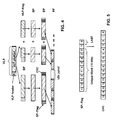
Figures 4 to 7 in the drawing are representative of an alternative approach based on flag separation of packets. This approach may in turn rely on two different solutions (bit processing or byte processing) to provide a safeguard signal. - In the arrangement shown in
figure 4 , no VLP packet maximum size is foreseen, while packet segmentation (VLP-frag) is still admitted. - After having generated a Simple Packet (SP) flow - essentially along the lines of the process already described in connection with
figure 1 , a Simple Packet Flag (SP-Flag) is inserted at the leading end of each packet in order to obtain an Extended Packet (EP). As in the case of the first embodiment described previously, a CRC code may be optionally added at the leading end of the packet. - The SP-Flag includes again a "Unique Word" (UW) plus a "Distinguish" bit and a "LAST" bit.
- During this step, possible Unique Word emulations (i.e. sequences of bits that accidentally reproduce the Unique Word) are searched within the Simple Packet P flow - e.g. by means of a "sliding" window - and an Inverse Distinguish bit (i.e. a bit set to the complementary value of the Distinguish bit included in the SP-Flag) is inserted after any occurrence of such an emulation.
- The Extended Packets thus formed are linked to form a Packet Flow (PF). Again, if a "hole", i.e. a discontinuity, is present in the Extended Packet Sequence one (or more) idle packets are inserted in the Extended Packet Sequence so that the resulting Packet Flow is exempt from discontinuities.
- Typically, the SP-Flag field is configured as illustrated in
figure 5 . The first 10 bits reproduce the Unique Word, then the Distinguish bit is inserted and finally there is a "LAST" bit to indicate if te packet is part of a bigger packet that has been split up. - In the alternative approach of
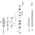
figures 6 and 7 , no VLP packet maximum size is foreseen and packet segmentation is not generally allowed, so that each VLP packet will generally map into one Simple Packet (SP). Once the Simple Packet flow is generated, in order to obtain an Extended Packet (EP), a SP-Flag that represents the "Unique Word" (UW) is again added at the leading end of each the Simple Packet, while a CRC-16 tail is optionally added after at the trailing end. - During this step, a byte stuffing technique is used to avoid idle flags into the Extended Packet stream.
- In so doing, two basic rules are enforced:
- each "emulation" of the Unique Word is replaced by the sequence Inserted Byte (IB) - UW Distinguish Byte (UW_DB);
- each occurrence of the Inserted Byte IB is replaced by the sequence IB - IB Distinguish Byte (IB_DB).
- UW_DB and IB_DB are calculated by X-oring (i.e. via an Exclusive-OR operation) DB and IB with Xoring Byte (XB) that is:
UW_DB = UW xor XB;
IB_DB = IB xor XB. - For instance, choosing UW = 0x7E, DB = 0x7D and XB = 0x20 the two basic rules are:
- each 0x7E occurrence is replaced by the sequence 0x7D 0x5E (Ox7E xor 0x20);
- each 0x7D occurrence is replaced by the sequence 0x7D 0x5D (Ox7D xor 0x20).
- The CRC-16 value is calculated over the data bytes before the stuffing process. So, the byte stuffing is performed without effects over the CRC-16 value. To perform the CRC-16 calculation, the initial value is set to 0xFFFF and the polynomial X16 + X12 + X5 + X0 is used to calculate the final result. This value is inverted (logical "NOT") and inserted after the packet data with MSB sent first.
- The Extended Packets are then linked to form the output Packet Flow (PF) to be used for transmission. When no VLP packet is present, one idle packet, formed by a single 0x7E byte, is joined to the PF.
- With all the arrangements described, no packet maximum size is foreseen. Moreover, in the case of the "framed" arrangement of
figures 1 to 3 , packet alignment is highly insensitive to Bit Error Rate and information on packet length is directly available via the First/Next Packet Pointer mechanism. If a control flag (e.g. CRC-16) is present, all the procedures described can control packet error and packets discard. - Additionally, different values for the Real Throughput (i.e. throughput of the incoming VLP signal) can be assured as a function of Theoretic Throughput (depending on PDH signal chosen) and Average Packet Length. The Segmentation And Reassembling (SAR) operations - if performed - lead to a relatively minor throughput degradation that can easily be calculated in all cases (the values refer to arrangements without CRC insertion).
- In the case of the arrangement of
figures 1 to 3 :
- In the case of the arrangement of
figures 4 and 5 , when '1s' and '0s' are equally probable:
- Finally, in the case of the arrangement of
figures 6 and 7 , again when '1s' and '0s' are equally probable:
- Different performance levels can be achieved with the various arrangements described in the foregoing, and different choices may be made in different context. -GFP.
- Both Packet Flow (PF) and Framed Packet Flow (FPF) signals generated as described in the foregoing can be mapped e.g. into one or more E1 (2048 Kbit/s) PDH signals. Preferably, this result can be achieved by resorting to the arrangement discloses in a co-pending application filed on even date by the same applicant.
- All the processing steps illustrated in
figures 1 ,5 , and6 can be performed by resorting to a dedicated processor system or a general purpose processor system suitably programmed (according to criteria that are known per se) to perform those processing steps. - In terms of Maximum Packet Length the GFP Payload Area is a variable length area that may include from 4 to 65535 octets. This means that packets of size up to 65535 bytes can be mapped into GFP packets as described herein.
- Without prejudice to the underlying principles of the invention, the details and the embodiments may vary, even appreciably, with reference to what has been described by way of example only, without departing from the scope of the invention as defined by the annexed claims.
Claims (18)
- A method of transmitting a Variable Length Packet (VLP) input data flow over a Plesiochronous Digital Hierarchy (PDH) channel, the method including the step of mapping said Variable Length Packet input data flow into a continuous packet flow for transmission over said Plesiochronous Digital Hierarchy channel, said continuous packet flow including subsequent partitioning bit strings wherein at least one bit string in a pair of said subsequent partitioning bit strings is indicative of the length of an associated packet in said continuous packet flow, the method including the step of inserting in said continuous packet flow a safeguard signal for said partitioning bit strings.
- The method of claim 1, further including the step of transmitting said continuous packet flow over one or more Plesiochronous Digital Hierarchy channels.
- The method of either of claims 1 or 2, including the step of adding a Cyclic Redundancy Code to the packets in said continuous packet flow.
- The method of any of claims 1 o 3, including the step of including idle packets in said continuous packet flow to ensure continuity thereof.
- The method of any of the previous claims, including the step of subjecting said packets in said Variable Length Packet input flow to fragmentation whereby packets longer than a given fragmentation threshold are fragmented into packets shorter than said fragmentation threshold in view of mapping into said continuous packet flow.
- The method of claim 5, including the step of including in said partitioning strings at least one bit indicative of the fact that associated packet is part of a longer packet that has been subject to fragmentation.
- The method of any of the previous claims, including the steps of:- providing in said partitioning strings pointers (FPP, NPP) comprising a pointing mechanism wherein each said pointer points to a subsequent pointer in said continuous packet flow; and- providing said safeguard signal as a frame signal with a fixed frame period (FPF) whereby said pointing mechanism is re-set at each frame of said frame signal.
- The method of claim 7, wherein each frame of said frame signal frames a First Packet Pointer followed by a set of Next Packet Pointers.
- The method of claims 5 and 7, wherein said fragmentation threshold and said fixed frame period are identical.
- The method of claim 9, wherein said fragmentation threshold and said fixed frame period are equal to 1024 bytes.
- The method of any of claims 6 to 10, including the step of adding in said partitioning strings an error correction code for the pointers in said partitioning strings.
- The method of claim 11, wherein said error correction code is selected as a code permitting correction of at least one errored bit and detection of up to two errored bits in the pointers in said partitioning strings.
- The method of any of claims 1 to 6, including the steps of:- providing in said partitioning strings flags each identificative of the presence of said associated packet in said continuous packet flow; and- providing said safeguard signal as a distinguishing signal for distinguishing said flags over any emulations thereof in said continuous packet flow.
- The method of claim 13, including the steps of:- associating with each said flag a distinguishing bit,- searching said continuous packet flow for any emulations of said flag; and- associating with any emulation found in said searching an inverse distinguishing bit with a value complementary to said distinguishing bit.
- The method of claim 13, including the steps of:- searching said continuous packet flow for any emulations of said flags;- replacing any flag emulation found in said searching by a sequence of an Inserted Byte (IB) and a Flag Distinguishing Byte (UW_DB);- searching in said continuous packet flow any emulations of said Inserted Byte (IB); and- replacing any emulation of said Inserted Byte IB located in said searching by a sequence of said Inserted Byte (IB) and an Inserted Byte Distinguish Byte (IB_DB).
- The method of claim 15, wherein said Flag
Distinguishing Byte (UW_DB) and said Inserted Byte
Distinguish Byte (IB_DB) are calculated by X-oring said Flag (UW) and said Inserted Byte IB with an Xoring Byte (XB). - A system for transmitting a Variable Length Packet (VLP) input data flow over a Plesiochronous Digital Hierarchy (PDH) channel, the system being configured to perform the method any of claims 1 to 16.
- A computer program product, directly loadable in the memory of at least one computer and including software code portions for performing the method of any of claims 1 to 16.
Priority Applications (3)
| Application Number | Priority Date | Filing Date | Title |
|---|---|---|---|
| AT07425440T ATE496441T1 (en) | 2007-07-18 | 2007-07-18 | METHOD AND SYSTEM FOR DATA TRANSMISSION VIA PDH CHANNELS AND CORRESPONDING COMPUTER PROGRAM |
| DE602007012076T DE602007012076D1 (en) | 2007-07-18 | 2007-07-18 | Method and system for data transmission via PDH channels and corresponding computer program |
| EP07425440A EP2017988B1 (en) | 2007-07-18 | 2007-07-18 | A method and system for transmitting data over PDH channels and corresponding computer program product |
Applications Claiming Priority (1)
| Application Number | Priority Date | Filing Date | Title |
|---|---|---|---|
| EP07425440A EP2017988B1 (en) | 2007-07-18 | 2007-07-18 | A method and system for transmitting data over PDH channels and corresponding computer program product |
Publications (2)
| Publication Number | Publication Date |
|---|---|
| EP2017988A1 true EP2017988A1 (en) | 2009-01-21 |
| EP2017988B1 EP2017988B1 (en) | 2011-01-19 |
Family
ID=38663134
Family Applications (1)
| Application Number | Title | Priority Date | Filing Date |
|---|---|---|---|
| EP07425440A Not-in-force EP2017988B1 (en) | 2007-07-18 | 2007-07-18 | A method and system for transmitting data over PDH channels and corresponding computer program product |
Country Status (3)
| Country | Link |
|---|---|
| EP (1) | EP2017988B1 (en) |
| AT (1) | ATE496441T1 (en) |
| DE (1) | DE602007012076D1 (en) |
Cited By (1)
| Publication number | Priority date | Publication date | Assignee | Title |
|---|---|---|---|---|
| US9344321B1 (en) | 2012-08-13 | 2016-05-17 | Microsemi Storage Solutions (U.S.), Inc. | Frame delineation method for a generic framing procedure |
-
2007
- 2007-07-18 AT AT07425440T patent/ATE496441T1/en not_active IP Right Cessation
- 2007-07-18 DE DE602007012076T patent/DE602007012076D1/en active Active
- 2007-07-18 EP EP07425440A patent/EP2017988B1/en not_active Not-in-force
Non-Patent Citations (4)
| Title |
|---|
| "Application Note 3849 - Ethernet-over-PDH Technology Overview", DALLAS SEMICONDUCTOR MAXIM, 30 May 2006 (2006-05-30), XP002459059, Retrieved from the Internet <URL:http://pdfserv.maxim-ic.com/en/an/AN3849.pdf> [retrieved on 20071116] * |
| "Generic framing procedure (GFP); G.7041/Y.1303 (08/05)", ITU-T STANDARD IN FORCE (I), INTERNATIONAL TELECOMMUNICATION UNION, GENEVA, CH, no. G7041/Y1303 8/5, 22 August 2005 (2005-08-22), XP017404569 * |
| "GFP frame mapping into Plesiochronous Digital Hierarchy (PDH); G.8040/Y.1340 (09/05)", ITU-T STANDARD IN FORCE (I), INTERNATIONAL TELECOMMUNICATION UNION, GENEVA, CH, no. G8040/Y1340 9/5, 6 September 2005 (2005-09-06), XP017404625 * |
| CHEN WENTAO ET AL.: "Performance Analysis of Two Ethernet over E1 Schemes", TSINGHUA SCI. TECH.; TSINGHUA SCIENCE AND TECHNOLOGY, vol. 12, no. 1, February 2007 (2007-02-01), State Key Laboratory on Microwave and Digital Communication Department of Electronic Engineering Tsinghua University, Beijing, 100084, China, pages 70 - 76, XP002458889, ISSN: 1007-0214 * |
Cited By (3)
| Publication number | Priority date | Publication date | Assignee | Title |
|---|---|---|---|---|
| US9344321B1 (en) | 2012-08-13 | 2016-05-17 | Microsemi Storage Solutions (U.S.), Inc. | Frame delineation method for a generic framing procedure |
| US9736275B1 (en) | 2012-08-13 | 2017-08-15 | Microsemi Solutions (U.S.), Inc. | Frame delineation method for a generic framing procedure |
| US10306027B2 (en) | 2012-08-13 | 2019-05-28 | Microsemi Solutions (U.S.), Inc. | Frame delineation method for a generic framing procedure |
Also Published As
| Publication number | Publication date |
|---|---|
| ATE496441T1 (en) | 2011-02-15 |
| EP2017988B1 (en) | 2011-01-19 |
| DE602007012076D1 (en) | 2011-03-03 |
Similar Documents
| Publication | Publication Date | Title |
|---|---|---|
| US7519080B2 (en) | Fibre channel frame-mode GFP with distributed delimiter | |
| US6098188A (en) | Packet framer | |
| EP1755248B1 (en) | Indication of lost segments across layer boundaries | |
| EP1871068B1 (en) | Method and device for generic framing procedure encapsulation | |
| US7725808B1 (en) | System and method for representing compressed information | |
| AU5254000A (en) | Encoding method of multimedia data and device thereof | |
| AU3079300A (en) | A data communication device and method in a cdma communication system | |
| US6993046B1 (en) | Mapping of block-encoded data formats onto a bit/byte synchronous transport medium | |
| EP1648133B1 (en) | A method for encapsulating data stream | |
| US9031415B2 (en) | Adaptor system for an Ethernet network | |
| US6819679B1 (en) | Multiprotocol packet framing technique | |
| EP2017988B1 (en) | A method and system for transmitting data over PDH channels and corresponding computer program product | |
| US7672330B2 (en) | Methods for sending and receiving network management messages and/or control messages | |
| US20060092979A1 (en) | Method and device of processing a generic framing procedure frame | |
| EP1067740A1 (en) | Method for transmitting variable sized packets from an upper layer of a stack of communication protocol layers to a lower layer intended to manage fixed sized packets | |
| EP1986363A1 (en) | Method, device and network element for decoding an information word from a coded word | |
| JP3270966B2 (en) | Error correction circuit | |
| CN100512289C (en) | Processing method for communication system transmitting and receiving data using general frame forming rule | |
| CN101035112B (en) | A device and method for transmitting additional information | |
| EP0555998B1 (en) | A packet framer | |
| CN111937329B (en) | Method for transmitting data and forwarding equipment | |
| CN116260553B (en) | Method, device and system for retransmitting data | |
| EP2207287B1 (en) | Reception of ethernet packets transported over a synchronous transport network | |
| KR100223215B1 (en) | Byte-Sorted Bit Stuffing Method | |
| JPH03258142A (en) | Packet transmission system |
Legal Events
| Date | Code | Title | Description |
|---|---|---|---|
| PUAI | Public reference made under article 153(3) epc to a published international application that has entered the european phase |
Free format text: ORIGINAL CODE: 0009012 |
|
| AK | Designated contracting states |
Kind code of ref document: A1 Designated state(s): AT BE BG CH CY CZ DE DK EE ES FI FR GB GR HU IE IS IT LI LT LU LV MC MT NL PL PT RO SE SI SK TR |
|
| AX | Request for extension of the european patent |
Extension state: AL BA HR MK RS |
|
| 17P | Request for examination filed |
Effective date: 20090721 |
|
| 17Q | First examination report despatched |
Effective date: 20090812 |
|
| AKX | Designation fees paid |
Designated state(s): AT BE BG CH CY CZ DE DK EE ES FI FR GB GR HU IE IS IT LI LT LU LV MC MT NL PL PT RO SE SI SK TR |
|
| GRAP | Despatch of communication of intention to grant a patent |
Free format text: ORIGINAL CODE: EPIDOSNIGR1 |
|
| GRAS | Grant fee paid |
Free format text: ORIGINAL CODE: EPIDOSNIGR3 |
|
| GRAA | (expected) grant |
Free format text: ORIGINAL CODE: 0009210 |
|
| AK | Designated contracting states |
Kind code of ref document: B1 Designated state(s): AT BE BG CH CY CZ DE DK EE ES FI FR GB GR HU IE IS IT LI LT LU LV MC MT NL PL PT RO SE SI SK TR |
|
| REG | Reference to a national code |
Ref country code: GB Ref legal event code: FG4D |
|
| REG | Reference to a national code |
Ref country code: CH Ref legal event code: EP |
|
| REG | Reference to a national code |
Ref country code: IE Ref legal event code: FG4D |
|
| REF | Corresponds to: |
Ref document number: 602007012076 Country of ref document: DE Date of ref document: 20110303 Kind code of ref document: P |
|
| REG | Reference to a national code |
Ref country code: DE Ref legal event code: R096 Ref document number: 602007012076 Country of ref document: DE Effective date: 20110303 |
|
| REG | Reference to a national code |
Ref country code: NL Ref legal event code: VDEP Effective date: 20110119 |
|
| LTIE | Lt: invalidation of european patent or patent extension |
Effective date: 20110119 |
|
| PG25 | Lapsed in a contracting state [announced via postgrant information from national office to epo] |
Ref country code: PT Free format text: LAPSE BECAUSE OF FAILURE TO SUBMIT A TRANSLATION OF THE DESCRIPTION OR TO PAY THE FEE WITHIN THE PRESCRIBED TIME-LIMIT Effective date: 20110519 Ref country code: LV Free format text: LAPSE BECAUSE OF FAILURE TO SUBMIT A TRANSLATION OF THE DESCRIPTION OR TO PAY THE FEE WITHIN THE PRESCRIBED TIME-LIMIT Effective date: 20110119 Ref country code: SE Free format text: LAPSE BECAUSE OF FAILURE TO SUBMIT A TRANSLATION OF THE DESCRIPTION OR TO PAY THE FEE WITHIN THE PRESCRIBED TIME-LIMIT Effective date: 20110119 Ref country code: GR Free format text: LAPSE BECAUSE OF FAILURE TO SUBMIT A TRANSLATION OF THE DESCRIPTION OR TO PAY THE FEE WITHIN THE PRESCRIBED TIME-LIMIT Effective date: 20110420 Ref country code: IS Free format text: LAPSE BECAUSE OF FAILURE TO SUBMIT A TRANSLATION OF THE DESCRIPTION OR TO PAY THE FEE WITHIN THE PRESCRIBED TIME-LIMIT Effective date: 20110519 Ref country code: ES Free format text: LAPSE BECAUSE OF FAILURE TO SUBMIT A TRANSLATION OF THE DESCRIPTION OR TO PAY THE FEE WITHIN THE PRESCRIBED TIME-LIMIT Effective date: 20110430 Ref country code: LT Free format text: LAPSE BECAUSE OF FAILURE TO SUBMIT A TRANSLATION OF THE DESCRIPTION OR TO PAY THE FEE WITHIN THE PRESCRIBED TIME-LIMIT Effective date: 20110119 |
|
| PG25 | Lapsed in a contracting state [announced via postgrant information from national office to epo] |
Ref country code: SI Free format text: LAPSE BECAUSE OF FAILURE TO SUBMIT A TRANSLATION OF THE DESCRIPTION OR TO PAY THE FEE WITHIN THE PRESCRIBED TIME-LIMIT Effective date: 20110119 Ref country code: PL Free format text: LAPSE BECAUSE OF FAILURE TO SUBMIT A TRANSLATION OF THE DESCRIPTION OR TO PAY THE FEE WITHIN THE PRESCRIBED TIME-LIMIT Effective date: 20110119 Ref country code: FI Free format text: LAPSE BECAUSE OF FAILURE TO SUBMIT A TRANSLATION OF THE DESCRIPTION OR TO PAY THE FEE WITHIN THE PRESCRIBED TIME-LIMIT Effective date: 20110119 Ref country code: AT Free format text: LAPSE BECAUSE OF FAILURE TO SUBMIT A TRANSLATION OF THE DESCRIPTION OR TO PAY THE FEE WITHIN THE PRESCRIBED TIME-LIMIT Effective date: 20110119 Ref country code: NL Free format text: LAPSE BECAUSE OF FAILURE TO SUBMIT A TRANSLATION OF THE DESCRIPTION OR TO PAY THE FEE WITHIN THE PRESCRIBED TIME-LIMIT Effective date: 20110119 Ref country code: BG Free format text: LAPSE BECAUSE OF FAILURE TO SUBMIT A TRANSLATION OF THE DESCRIPTION OR TO PAY THE FEE WITHIN THE PRESCRIBED TIME-LIMIT Effective date: 20110419 Ref country code: BE Free format text: LAPSE BECAUSE OF FAILURE TO SUBMIT A TRANSLATION OF THE DESCRIPTION OR TO PAY THE FEE WITHIN THE PRESCRIBED TIME-LIMIT Effective date: 20110119 Ref country code: CY Free format text: LAPSE BECAUSE OF FAILURE TO SUBMIT A TRANSLATION OF THE DESCRIPTION OR TO PAY THE FEE WITHIN THE PRESCRIBED TIME-LIMIT Effective date: 20110119 |
|
| PG25 | Lapsed in a contracting state [announced via postgrant information from national office to epo] |
Ref country code: EE Free format text: LAPSE BECAUSE OF FAILURE TO SUBMIT A TRANSLATION OF THE DESCRIPTION OR TO PAY THE FEE WITHIN THE PRESCRIBED TIME-LIMIT Effective date: 20110119 Ref country code: DK Free format text: LAPSE BECAUSE OF FAILURE TO SUBMIT A TRANSLATION OF THE DESCRIPTION OR TO PAY THE FEE WITHIN THE PRESCRIBED TIME-LIMIT Effective date: 20110119 |
|
| PLBE | No opposition filed within time limit |
Free format text: ORIGINAL CODE: 0009261 |
|
| STAA | Information on the status of an ep patent application or granted ep patent |
Free format text: STATUS: NO OPPOSITION FILED WITHIN TIME LIMIT |
|
| PG25 | Lapsed in a contracting state [announced via postgrant information from national office to epo] |
Ref country code: RO Free format text: LAPSE BECAUSE OF FAILURE TO SUBMIT A TRANSLATION OF THE DESCRIPTION OR TO PAY THE FEE WITHIN THE PRESCRIBED TIME-LIMIT Effective date: 20110119 Ref country code: CZ Free format text: LAPSE BECAUSE OF FAILURE TO SUBMIT A TRANSLATION OF THE DESCRIPTION OR TO PAY THE FEE WITHIN THE PRESCRIBED TIME-LIMIT Effective date: 20110119 Ref country code: SK Free format text: LAPSE BECAUSE OF FAILURE TO SUBMIT A TRANSLATION OF THE DESCRIPTION OR TO PAY THE FEE WITHIN THE PRESCRIBED TIME-LIMIT Effective date: 20110119 |
|
| 26N | No opposition filed |
Effective date: 20111020 |
|
| PG25 | Lapsed in a contracting state [announced via postgrant information from national office to epo] |
Ref country code: IT Free format text: LAPSE BECAUSE OF FAILURE TO SUBMIT A TRANSLATION OF THE DESCRIPTION OR TO PAY THE FEE WITHIN THE PRESCRIBED TIME-LIMIT Effective date: 20110119 Ref country code: MT Free format text: LAPSE BECAUSE OF FAILURE TO SUBMIT A TRANSLATION OF THE DESCRIPTION OR TO PAY THE FEE WITHIN THE PRESCRIBED TIME-LIMIT Effective date: 20110119 |
|
| REG | Reference to a national code |
Ref country code: DE Ref legal event code: R097 Ref document number: 602007012076 Country of ref document: DE Effective date: 20111020 |
|
| PG25 | Lapsed in a contracting state [announced via postgrant information from national office to epo] |
Ref country code: MC Free format text: LAPSE BECAUSE OF NON-PAYMENT OF DUE FEES Effective date: 20110731 |
|
| REG | Reference to a national code |
Ref country code: CH Ref legal event code: PL |
|
| REG | Reference to a national code |
Ref country code: IE Ref legal event code: MM4A |
|
| PG25 | Lapsed in a contracting state [announced via postgrant information from national office to epo] |
Ref country code: LI Free format text: LAPSE BECAUSE OF NON-PAYMENT OF DUE FEES Effective date: 20110731 Ref country code: CH Free format text: LAPSE BECAUSE OF NON-PAYMENT OF DUE FEES Effective date: 20110731 |
|
| PG25 | Lapsed in a contracting state [announced via postgrant information from national office to epo] |
Ref country code: IE Free format text: LAPSE BECAUSE OF NON-PAYMENT OF DUE FEES Effective date: 20110718 |
|
| REG | Reference to a national code |
Ref country code: GB Ref legal event code: 732E Free format text: REGISTERED BETWEEN 20120719 AND 20120725 |
|
| REG | Reference to a national code |
Ref country code: AT Ref legal event code: MK05 Ref document number: 496441 Country of ref document: AT Kind code of ref document: T Effective date: 20110119 |
|
| REG | Reference to a national code |
Ref country code: DE Ref legal event code: R081 Ref document number: 602007012076 Country of ref document: DE Owner name: DRAGONWAVE S.A R.L., LU Free format text: FORMER OWNER: NOKIA SIEMENS NETWORKS S.P.A., MILANO, IT Effective date: 20120731 Ref country code: DE Ref legal event code: R081 Ref document number: 602007012076 Country of ref document: DE Owner name: NOKIA SIEMENS NETWORKS ITALIA S.P.A., IT Free format text: FORMER OWNER: NOKIA SIEMENS NETWORKS S.P.A., MILANO, IT Effective date: 20120731 |
|
| PG25 | Lapsed in a contracting state [announced via postgrant information from national office to epo] |
Ref country code: LU Free format text: LAPSE BECAUSE OF NON-PAYMENT OF DUE FEES Effective date: 20110718 |
|
| REG | Reference to a national code |
Ref country code: FR Ref legal event code: CA Effective date: 20130426 Ref country code: FR Ref legal event code: CD Owner name: NOKIA SIEMENS NETWORKS ITALIA S.P.A., IT Effective date: 20130426 |
|
| REG | Reference to a national code |
Ref country code: FR Ref legal event code: CA Effective date: 20130607 Ref country code: FR Ref legal event code: TP Owner name: NOKIA SIEMENS NETWORKS ITALIA S.P.A., IT Effective date: 20130607 |
|
| PG25 | Lapsed in a contracting state [announced via postgrant information from national office to epo] |
Ref country code: TR Free format text: LAPSE BECAUSE OF FAILURE TO SUBMIT A TRANSLATION OF THE DESCRIPTION OR TO PAY THE FEE WITHIN THE PRESCRIBED TIME-LIMIT Effective date: 20110119 |
|
| PG25 | Lapsed in a contracting state [announced via postgrant information from national office to epo] |
Ref country code: HU Free format text: LAPSE BECAUSE OF FAILURE TO SUBMIT A TRANSLATION OF THE DESCRIPTION OR TO PAY THE FEE WITHIN THE PRESCRIBED TIME-LIMIT Effective date: 20110119 |
|
| REG | Reference to a national code |
Ref country code: FR Ref legal event code: PLFP Year of fee payment: 9 |
|
| PGFP | Annual fee paid to national office [announced via postgrant information from national office to epo] |
Ref country code: FR Payment date: 20150629 Year of fee payment: 9 |
|
| PG25 | Lapsed in a contracting state [announced via postgrant information from national office to epo] |
Ref country code: FR Free format text: LAPSE BECAUSE OF NON-PAYMENT OF DUE FEES Effective date: 20160801 |
|
| REG | Reference to a national code |
Ref country code: FR Ref legal event code: ST Effective date: 20170331 |
|
| REG | Reference to a national code |
Ref country code: DE Ref legal event code: R081 Ref document number: 602007012076 Country of ref document: DE Owner name: DRAGONWAVE S.A R.L., LU Free format text: FORMER OWNER: NOKIA SIEMENS NETWORKS ITALIA S.P.A., CASSINA DE PECCHI, IT |
|
| PGFP | Annual fee paid to national office [announced via postgrant information from national office to epo] |
Ref country code: DE Payment date: 20170724 Year of fee payment: 11 Ref country code: GB Payment date: 20170719 Year of fee payment: 11 |
|
| REG | Reference to a national code |
Ref country code: DE Ref legal event code: R119 Ref document number: 602007012076 Country of ref document: DE |
|
| GBPC | Gb: european patent ceased through non-payment of renewal fee |
Effective date: 20180718 |
|
| PG25 | Lapsed in a contracting state [announced via postgrant information from national office to epo] |
Ref country code: GB Free format text: LAPSE BECAUSE OF NON-PAYMENT OF DUE FEES Effective date: 20180718 Ref country code: DE Free format text: LAPSE BECAUSE OF NON-PAYMENT OF DUE FEES Effective date: 20190201 |