EP2017981A1 - Method to increase the SNR in optical OFDM systems - Google Patents
Method to increase the SNR in optical OFDM systems Download PDFInfo
- Publication number
- EP2017981A1 EP2017981A1 EP07290887A EP07290887A EP2017981A1 EP 2017981 A1 EP2017981 A1 EP 2017981A1 EP 07290887 A EP07290887 A EP 07290887A EP 07290887 A EP07290887 A EP 07290887A EP 2017981 A1 EP2017981 A1 EP 2017981A1
- Authority
- EP
- European Patent Office
- Prior art keywords
- data signal
- data signals
- complex
- signal
- modified
- Prior art date
- Legal status (The legal status is an assumption and is not a legal conclusion. Google has not performed a legal analysis and makes no representation as to the accuracy of the status listed.)
- Withdrawn
Links
- 230000003287 optical effect Effects 0.000 title claims abstract description 62
- 238000000034 method Methods 0.000 title claims description 40
- 230000005540 biological transmission Effects 0.000 claims abstract description 12
- 230000002238 attenuated effect Effects 0.000 claims abstract description 9
- 239000003607 modifier Substances 0.000 claims description 13
- 230000003321 amplification Effects 0.000 claims description 4
- 238000003199 nucleic acid amplification method Methods 0.000 claims description 4
- 238000012886 linear function Methods 0.000 claims 4
- 238000006243 chemical reaction Methods 0.000 description 3
- 230000000694 effects Effects 0.000 description 3
- 230000001131 transforming effect Effects 0.000 description 3
- 230000003247 decreasing effect Effects 0.000 description 2
- 239000006185 dispersion Substances 0.000 description 2
- 230000010365 information processing Effects 0.000 description 2
- 239000000203 mixture Substances 0.000 description 2
- 239000013307 optical fiber Substances 0.000 description 2
- RYGMFSIKBFXOCR-UHFFFAOYSA-N Copper Chemical compound [Cu] RYGMFSIKBFXOCR-UHFFFAOYSA-N 0.000 description 1
- 230000009286 beneficial effect Effects 0.000 description 1
- 229910052802 copper Inorganic materials 0.000 description 1
- 239000010949 copper Substances 0.000 description 1
- 238000007620 mathematical function Methods 0.000 description 1
- 230000009466 transformation Effects 0.000 description 1
Images


Classifications
-
- H—ELECTRICITY
- H04—ELECTRIC COMMUNICATION TECHNIQUE
- H04B—TRANSMISSION
- H04B10/00—Transmission systems employing electromagnetic waves other than radio-waves, e.g. infrared, visible or ultraviolet light, or employing corpuscular radiation, e.g. quantum communication
- H04B10/50—Transmitters
- H04B10/501—Structural aspects
- H04B10/503—Laser transmitters
- H04B10/505—Laser transmitters using external modulation
-
- H—ELECTRICITY
- H04—ELECTRIC COMMUNICATION TECHNIQUE
- H04B—TRANSMISSION
- H04B10/00—Transmission systems employing electromagnetic waves other than radio-waves, e.g. infrared, visible or ultraviolet light, or employing corpuscular radiation, e.g. quantum communication
- H04B10/25—Arrangements specific to fibre transmission
- H04B10/2507—Arrangements specific to fibre transmission for the reduction or elimination of distortion or dispersion
-
- H—ELECTRICITY
- H04—ELECTRIC COMMUNICATION TECHNIQUE
- H04B—TRANSMISSION
- H04B10/00—Transmission systems employing electromagnetic waves other than radio-waves, e.g. infrared, visible or ultraviolet light, or employing corpuscular radiation, e.g. quantum communication
- H04B10/50—Transmitters
- H04B10/58—Compensation for non-linear transmitter output
-
- H—ELECTRICITY
- H04—ELECTRIC COMMUNICATION TECHNIQUE
- H04B—TRANSMISSION
- H04B10/00—Transmission systems employing electromagnetic waves other than radio-waves, e.g. infrared, visible or ultraviolet light, or employing corpuscular radiation, e.g. quantum communication
- H04B10/60—Receivers
- H04B10/66—Non-coherent receivers, e.g. using direct detection
-
- H—ELECTRICITY
- H04—ELECTRIC COMMUNICATION TECHNIQUE
- H04J—MULTIPLEX COMMUNICATION
- H04J14/00—Optical multiplex systems
- H04J14/02—Wavelength-division multiplex systems
- H04J14/0298—Wavelength-division multiplex systems with sub-carrier multiplexing [SCM]
-
- H—ELECTRICITY
- H04—ELECTRIC COMMUNICATION TECHNIQUE
- H04L—TRANSMISSION OF DIGITAL INFORMATION, e.g. TELEGRAPHIC COMMUNICATION
- H04L27/00—Modulated-carrier systems
- H04L27/26—Systems using multi-frequency codes
- H04L27/2601—Multicarrier modulation systems
- H04L27/2626—Arrangements specific to the transmitter only
-
- H—ELECTRICITY
- H04—ELECTRIC COMMUNICATION TECHNIQUE
- H04L—TRANSMISSION OF DIGITAL INFORMATION, e.g. TELEGRAPHIC COMMUNICATION
- H04L27/00—Modulated-carrier systems
- H04L27/26—Systems using multi-frequency codes
- H04L27/2601—Multicarrier modulation systems
- H04L27/2697—Multicarrier modulation systems in combination with other modulation techniques
-
- H—ELECTRICITY
- H04—ELECTRIC COMMUNICATION TECHNIQUE
- H04L—TRANSMISSION OF DIGITAL INFORMATION, e.g. TELEGRAPHIC COMMUNICATION
- H04L27/00—Modulated-carrier systems
- H04L27/32—Carrier systems characterised by combinations of two or more of the types covered by groups H04L27/02, H04L27/10, H04L27/18 or H04L27/26
- H04L27/34—Amplitude- and phase-modulated carrier systems, e.g. quadrature-amplitude modulated carrier systems
- H04L27/36—Modulator circuits; Transmitter circuits
- H04L27/366—Arrangements for compensating undesirable properties of the transmission path between the modulator and the demodulator
-
- H—ELECTRICITY
- H04—ELECTRIC COMMUNICATION TECHNIQUE
- H04L—TRANSMISSION OF DIGITAL INFORMATION, e.g. TELEGRAPHIC COMMUNICATION
- H04L27/00—Modulated-carrier systems
- H04L27/26—Systems using multi-frequency codes
- H04L27/2601—Multicarrier modulation systems
- H04L27/2614—Peak power aspects
Definitions
- the invention relates to a method for optical data transmission comprising the steps of generating a data signal utilizing orthogonal frequency division multiplexing, modulating an optical signal based on characteristics of the data signal, and transmitting the modulated optical signal.
- the invention also relates to a transmitter for transmitting optical data using orthogonal frequency division multiplexing, the transmitter comprising a modulator for modulating an optical signal based on characteristics of a data signal, the data signal comprising lower amplitudes and higher amplitudes.
- the invention relates to a receiver for receiving an optical orthogonal frequency division multiplexed signal, the receiver comprising a transformer for transforming the received optical signal into a received data signal, the received data signal comprising lower amplitudes and higher amplitudes.
- the invention relates to a system for optical data transmission, the system comprising a transmitter for transmitting optical data using orthogonal frequency division multiplexing and a receiver for receiving an optical orthogonal frequency division multiplexed signal from the transmitter, the transmitter comprising a modulator for modulating an optical signal based on characteristics of a data signal, the data signal comprising lower amplitudes and higher amplitudes, and the receiver comprising a transformer for transforming the received optical signal into a received data signal, the received data signal comprising lower amplitudes and higher amplitudes.
- OFDM orthogonal frequency division multiplexing
- DAB Digital Audio Broadcasting
- ADSL Asymmetric Digital Subscriber Line
- POTS Plane Old Telephone Service
- OFDM enables to encode each of multiple data channels into at least one of a set of closely-spaced orthogonal subcarriers, wherein the subcarriers are mapped on integer multiples of 1/T, where T is the duration of one of the parallel data bits that have to be transmitted from the data channels.
- T is the duration of one of the parallel data bits that have to be transmitted from the data channels.
- T is the duration of one of the parallel data bits that have to be transmitted from the data channels.
- the subcarriers are orthogonal.
- the waveforms of each of the individual subcarriers are summed, i.e. multiplexed, to produce a block of transmitted waveform for each set of parallel data bits.
- each subcarrier is separated, i.e. splitted, and then decoded.
- OFDM orthogonal frequency division multiplexing
- the OFDM signal mostly has a small amplitude with occasionally high amplitude. This means, that the OFDM signal has a small variance with high maxima, which corresponds to a high peak-to-average power ratio (PAPR).
- PAPR peak-to-average power ratio
- SNR signal-to-noise ratio
- a modified data signal is generated by applying a non-linear functionality to the data signal.
- the non-linear functionality causes at least lower amplitudes of the data signal to be amplified.
- the non-linear functionality is further characterized in that at least the highest amplitude is not amplified.
- the optical signal is then modulated based on characteristics of the modified data signal.
- the inventive method enables to amplify lower amplitudes of the data signal. This has the effect that the PAPR is reduced and the signal-to-noise ratio (SNR) for the lower amplitudes is increased. Since the OFDM signal mostly has a small amplitude with occasionally high amplitude, the average signal-to-noise ratio is increased.
- the first non-linear functionality further causes higher amplitudes of the data signal to be attenuated, which means that the first non-linear functionality has a compressing characteristic.
- This embodiment enables to increase the SNR and to decrease non-linearities, in particular clipping, since the amount of the highest amplitude is decreased.
- the degree of amplification and/or attenuation depends on the amplitude. This allows e.g. to increase the amplification of a signal, the lower the amplitudes of the signal are and to increase the attenuation of a signal, the higher the amplitudes of the signal are. This further enables to increase the SNR, since the distances between frequently occurring (low) amplitudes can be increased, wherein the distances between infrequently occurring high amplitudes are not increased at all or even decreased.
- the method further comprises the steps of generating complex-valued parallel analog data signals and electrically mixing the complex-valued parallel analog data signals.
- the complex-valued parallel analog data signals could be generated for example using an inverse fast Fourier transformation (IFFT) followed by a parallel-to-serial conversion and a digital-to-analog conversion, before electrically mixing the complex-valued parallel analog data signals.
- IFFT inverse fast Fourier transformation
- the electrically mixed analog data signal is then modified by applying the first non-linear functionality.
- modified data signals are generated based on the complex-valued parallel analog data signals, prior to electrically mixing the modified parallel analog data signals.
- modified data signals are generated based on complex-valued parallel digital data signals, prior to performing the digital-to-analog conversions and electrically mixing the signals.
- the non-linear functionality is preferably realized by a digital functionality.
- the non-linear functionality is realized by the digital-to-analog converter in that non-equidistant levels are applied for converting the digital data signals into modified analog data signals.
- the transmitted modulated optical signal is received and transformed into a received data signal.
- a second non-linear functionality is then applied to the received data signal, wherein the second non-linear functionality causes at least lower amplitudes of the received data signal to be attenuated and wherein the second non-linear functionality does not cause at least the highest amplitude to be attenuated.
- de-multiplexed parallel data signals are generated.
- the second non-linear functionality further causes higher amplitudes of the data signal to be amplified.
- the second non-linear functionality can be realized as the inverse of the first non-linear functionality.
- the de-modified data signal corresponds to the data signal prior to transmitting, and in particular prior to applying the first non-linear functionality.
- the second non-linear functionality is realized as a quasi-inverse of the first non-linear functionality.
- a quasi-inverse means that the second non-linear functionality is not the exact inverse of the first non-linear functionality, but has a similar effect.
- applying a quasi-inverse non-linear functionality often results in a de-modulated data signal that is sufficiently precise in order to determine the original information from the received data signal.
- the second non-linear functionality is adapted to at least one characteristic of the optical noise.
- the adaption could be performed by pre-adjusting the second non-linear functionality.
- the adaption could be performed based on determination of the optical noise. Since the optical noise is converted into non-linear noise while transforming the received optical signal, the second non-linear functionality could be adapted in order to further increase the signal-to-noise ratio.
- the adaption could be performed by having the second functionality parameterised and adjusting one or more parameters of the second non-linear functionality.
- the method further comprises the step of generating complex-valued parallel data signals by splitting the de-modified received data signal and generating de-multiplexed parallel data signals based on the complex-valued parallel data signals.
- the received data signal is split in order to generate complex-valued parallel analog data signals and then the second non-linear functionality is applied to the complex-valued parallel analog data signals in order to generate de-modified parallel analog data signals.
- the second non-linear functionality it is also conceivable to apply the second non-linear functionality not until converting the complex-valued parallel analog data signals into complex-valued parallel digital data signals using an analog-to-digital converter, which means that the second non-linear functionality could be realized by a digital functionality, in particular by applying non-equidistant levels when converting the complex-valued parallel analog data signals into de-modified digital data signals.
- the transmitter comprises a modifier realizing a non-linear functionality, wherein the modifier is adapted to amplify at least lower amplitudes and to not amplify at least the highest amplitude.
- receiver comprises a modifier realizing a non-linear functionality, wherein the modifier is adapted to attenuate at least the lower amplitudes and to not attenuate at least the highest amplitude of the received data signal.
- the transmitter and receiver are adapted to execute the inventive method.
- the object is further solved by a system as mentioned above, wherein the system comprises the inventive transmitter and the inventive receiver.
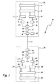
- Figure 1 shows a system 1a comprising a transmitter 2a and a receiver 3a.
- the transmitter 2a and the receiver 3a are connected via an optical fiber 4 for optical data transmission.
- transmitter 2a and receiver 3a could also be connected via several further information processing elements, and in particular via several optical information processing elements, such as optical routers or amplifiers.
- the transmitter 2a comprises an encoder 5 for encoding a predefined number of data bits.
- the encoder 5 could for example be realized using a quadrature-amplitude-modulation (QAM), enabling to encode pairs of data bits as four possible phases.
- QAM quadrature-amplitude-modulation
- the transmitter 2a further comprises a transformer 6.
- the transformer 6 could be realized by performing an inverse fast Fourier transform (IFFT) on the parallel encoded signals received from encoder 5. If, for example, each QAM channel is presented to an input of the IFFT, the IFFT will produce an output comprising complex-valued parallel digital data signals.
- IFFT inverse fast Fourier transform
- the transmitter 2a further comprises parallel-to-serial converters 7, 8, wherein the parallel-to-serial converter 7 converts the real part of the complex-valued parallel digital data signals into the real part of a complex-valued serial digital data signal 9 and the parallel-to-serial converter 8 converts the imaginary part of the complex-valued parallel digital data signals into an imaginary part of a complex-valued serial digital data signal 10.
- the transmitter 2a further comprises digital/analog converters 11, 12 for converting the real part and the imaginary part of the complex-valued serial digital data signals 9, 10 into complex-valued analog data signals 13, 14.
- the transmitter 2a also comprises an electrical mixer 15, an electric circuit block realizing a first non-linear functionality 17, a modulator 19 and an optical light source 20.
- the optical light source 20 can be realized as a laser diode.
- the electrical mixer 15 is adapted to generate an analog data signal 16 by electrically mixing the complex-valued analog data signals 13, 14.
- the analog data signal 16 is then fed to the electric circuit block in order to apply the non-linear functionality 17 to the analog data signal 16.
- the non-linear functionality 17 causes the lower amplitudes of the analog data signal 16 to be amplified.
- the non-linear functionality 17 further attenuates the higher amplitudes of the analog data signal 16, which means, that the non-linear functionality 17 also compresses the analog data signal by attenuating the higher amplitudes.
- the non-linear functionality 17 increases the amount of distance between different lower amplitudes by amplifying the lower amplitudes and thus amplifying the amount of differences between the lower amplitudes.
- the amplitudes of the modified data signal 18 are more equidistant than the distances between the amplitudes of the data signal 16.
- the average signal-to-noise ratio is increased.
- the degree of amplification might be based on the amplitude of the data signal 16.
- the modified data signal 18 then drives the modulator 19 in order to modulate the signal generated by e.g. the optical light source 20, preferably adjusted by a bias (not shown in figure 1 ).
- the modulator 19 could be realized as a MZI (Mach-Zehnder Interferometer), generating an intensity-modulated optical data signal for transmission via optical fiber 4.
- the receiver 3a basically allows a reverse processing of the received optical signal. Therefore, the receiver 3a comprises an optical/electrical converter 49, preferably also comprising an optical amplifier (not shown in figure 1 ).
- the optical/electrical converter 49 generates a received analog data signal 48. Since the transmitter 2a has modified the analog data signal 16 in order to generate modified data signal 18, the received data signal 48 resembles the modified data signal 18.
- receiver 3a In order to demodulate the received data signal 48, receiver 3a provides an electric circuit block realizing a second non-linear functionality 47.
- the second non-linear functionality 47 could be the inverse of the first non-linear functionality 17. However, it is also conceivable that the second non-linear functionality only realizes an approximated inverse of the first non-linear functionality 17.
- Receiver 3a further comprises an electrical splitter 45 for generating complex-valued analog data signals 43, 44 comprising an imaginary part 44 and a real part 43.
- the complex-valued analog data signals 43, 44 are then digitized by analog-to-digital converters 41, 42, resulting in complex-valued digital data signals 39, 40.
- Receiver 3a further comprises serial-to-parallel converters 37, 38 in order to generate parallel data signals, each of them are presented to an input of a transformer 36.
- Transformer 36 could be realized as a fast Fourier transform (FFT) for generating signals that are then decoded by a decoder 35, in order to generate parallel data bits that correspond to the original data channels.
- FFT fast Fourier transform
- the system 1a realizes the inventive method by utilizing the first non-linear functionality 17 in order to amplify lower amplitudes of the analog data signal 16 and by attenuating higher amplitudes of the analog data signal 16.
- the non-linear functionality 17 preferably comprises a logarithmic function or a power function, wherein the non-linear functionality 17 might be chosen to characteristics of the transmitter 2a, e. g. based on data encoding performed by encoder 5, the implementation of transformer 6 or electrical and optical characteristics of modulator 19, light source 20 or a current bias.
- Receiver 3a receiving the modulated optical signal demodulates the signal by applying the second non-linear functionality 47. Therefore, the second non-linear functionality 47 is realized as the inverse or quasi-inverse of non-linear functionality 17. Furthermore, non-linear functionality 47 could further be enhanced by a functionality which adapts the received data signal to the optical noise that arose while transmitting the signal and that is converted into non-linear noise by the optical/electrical converter, e. g. by the photodiode.
- FIG. 2 shows a system 1b comprising transmitter 2b and receiver 3b.
- Transmitter 2b comprises two non-linear functionalities 17, each of them located at one path of the complex-valued analog data signals 13, 14 in order to generate complex-valued modified analog data signals 21, 22.
- the complex-valued modified analog data signals 21, 22 are then electrically mixed.
- Receiver 3b shows an architecture corresponding to transmitter 2b, in that receiver 3b comprises two non-linear functionalities 47, each located in the complex-valued analog data path.
- FIG. 3 shows a system 1c comprising transmitter 2c and receiver 3c, realizing another embodiment.
- Transmitter 2c comprises two non-linear functionalities 17a that are also located in the complex-valued data path.
- non-linear functionalities 17a are now located in the digital domain which means that they modulate complex-valued digital data signals 9, 10 in order to generate modified complex-valued digital data signals 23, 24.
- the non-linear functionalities 17a are part of the digital/analog converters 11, 12, e. g. by generating analog waveforms that realize more or less equidistant levels of the different amplitudes.
- receiver 3c is designed in correspondence with transmitter 2c.
- receiver 3c comprises non-linear functionalities 47a that are located in the digital domain of the complex-valued data path.
- Systems 1a, 1b, and 1c exemplify several embodiments of the present invention, in order to show the basic concepts. Further embodiments could in particular include a system comprising a transmitter and a receiver, wherein the design of the receiver does not totally correspond to the design of the transmitter. For example it is conceivable that transmitter 2c transmits optical data signals that are received by receiver 3a. Of course, several further combinations are conceivable.
- the transmitter 2a, 2b, and 2c as well as the receiver 3a, 3b, and 3c might comprise several further components as are commonly known in the art.
- the transmitter 2a, 2b, and 2c and/or the receiver 3a, 3b, and 3c might comprise optical filters or further amplifiers.
- the signals might be modulated according to several further modulation schemes.
Landscapes
- Engineering & Computer Science (AREA)
- Computer Networks & Wireless Communication (AREA)
- Signal Processing (AREA)
- Physics & Mathematics (AREA)
- Electromagnetism (AREA)
- Optics & Photonics (AREA)
- Nonlinear Science (AREA)
- Optical Communication System (AREA)
Abstract
Description
- The invention relates to a method for optical data transmission comprising the steps of generating a data signal utilizing orthogonal frequency division multiplexing, modulating an optical signal based on characteristics of the data signal, and transmitting the modulated optical signal.
- The invention also relates to a transmitter for transmitting optical data using orthogonal frequency division multiplexing, the transmitter comprising a modulator for modulating an optical signal based on characteristics of a data signal, the data signal comprising lower amplitudes and higher amplitudes.
- Furthermore, the invention relates to a receiver for receiving an optical orthogonal frequency division multiplexed signal, the receiver comprising a transformer for transforming the received optical signal into a received data signal, the received data signal comprising lower amplitudes and higher amplitudes.
- Finally, the invention relates to a system for optical data transmission, the system comprising a transmitter for transmitting optical data using orthogonal frequency division multiplexing and a receiver for receiving an optical orthogonal frequency division multiplexed signal from the transmitter, the transmitter comprising a modulator for modulating an optical signal based on characteristics of a data signal, the data signal comprising lower amplitudes and higher amplitudes, and the receiver comprising a transformer for transforming the received optical signal into a received data signal, the received data signal comprising lower amplitudes and higher amplitudes.
- Data transmission based on orthogonal frequency division multiplexing (OFDM) is commonly known and used for example in DAB (Digital Audio Broadcasting) systems or ADSL (Asymmetric Digital Subscriber Line) broadband access via POTS (Plane Old Telephone Service) copper wiring. OFDM enables to encode each of multiple data channels into at least one of a set of closely-spaced orthogonal subcarriers, wherein the subcarriers are mapped on integer multiples of 1/T, where T is the duration of one of the parallel data bits that have to be transmitted from the data channels. Thus, the subcarriers are orthogonal. The waveforms of each of the individual subcarriers are summed, i.e. multiplexed, to produce a block of transmitted waveform for each set of parallel data bits. At the receiver, each subcarrier is separated, i.e. splitted, and then decoded.
- Using OFDM for optical data transmission can be beneficial since it allows the symbol rate to be reduced, thus increasing tolerance to chromatic dispersion and polarisation mode dispersion, which in turn allows to transmit data on an increased distance.
- In the time domain, the OFDM signal mostly has a small amplitude with occasionally high amplitude. This means, that the OFDM signal has a small variance with high maxima, which corresponds to a high peak-to-average power ratio (PAPR). In order to avoid non-linearities, e. g. clipping, on the one hand and to limit the power consumption on the other hand, most of the signal has a poor signal-to-noise ratio (SNR), when noise, especially optical noise, is added.
- It is therefore an object of the invention to provide method and apparatus for increasing the signal-to-noise ratio in an optical OFDM system.
- This object is solved by a method for optical data transmission, wherein a modified data signal is generated by applying a non-linear functionality to the data signal. The non-linear functionality causes at least lower amplitudes of the data signal to be amplified. However, the non-linear functionality is further characterized in that at least the highest amplitude is not amplified. The optical signal is then modulated based on characteristics of the modified data signal.
- The inventive method enables to amplify lower amplitudes of the data signal. This has the effect that the PAPR is reduced and the signal-to-noise ratio (SNR) for the lower amplitudes is increased. Since the OFDM signal mostly has a small amplitude with occasionally high amplitude, the average signal-to-noise ratio is increased.
- Preferably, the first non-linear functionality further causes higher amplitudes of the data signal to be attenuated, which means that the first non-linear functionality has a compressing characteristic. This embodiment enables to increase the SNR and to decrease non-linearities, in particular clipping, since the amount of the highest amplitude is decreased.
- Advantageously, the degree of amplification and/or attenuation depends on the amplitude. This allows e.g. to increase the amplification of a signal, the lower the amplitudes of the signal are and to increase the attenuation of a signal, the higher the amplitudes of the signal are. This further enables to increase the SNR, since the distances between frequently occurring (low) amplitudes can be increased, wherein the distances between infrequently occurring high amplitudes are not increased at all or even decreased.
- The non-linear functionality preferably is realized as a logarithmic function or a power function. These types of functions are well-known and can be implemented as an electrical circuit or as a digital function. Examples for such non-linear functionalities are y = x½, y = x¼, or y = log(x).
- According to a preferred embodiment of the present invention, the method further comprises the steps of generating complex-valued parallel analog data signals and electrically mixing the complex-valued parallel analog data signals. The complex-valued parallel analog data signals could be generated for example using an inverse fast Fourier transformation (IFFT) followed by a parallel-to-serial conversion and a digital-to-analog conversion, before electrically mixing the complex-valued parallel analog data signals. The electrically mixed analog data signal is then modified by applying the first non-linear functionality.
- According to another embodiment of the present invention, modified data signals are generated based on the complex-valued parallel analog data signals, prior to electrically mixing the modified parallel analog data signals.
- According to still another embodiment of the present invention, modified data signals are generated based on complex-valued parallel digital data signals, prior to performing the digital-to-analog conversions and electrically mixing the signals. In this embodiment, the non-linear functionality is preferably realized by a digital functionality. Advantageously, the non-linear functionality is realized by the digital-to-analog converter in that non-equidistant levels are applied for converting the digital data signals into modified analog data signals.
- According to a preferred embodiment of the present invention, the transmitted modulated optical signal is received and transformed into a received data signal. A second non-linear functionality is then applied to the received data signal, wherein the second non-linear functionality causes at least lower amplitudes of the received data signal to be attenuated and wherein the second non-linear functionality does not cause at least the highest amplitude to be attenuated. Based on the de-modified received data signals, de-multiplexed parallel data signals are generated. Preferably, the second non-linear functionality further causes higher amplitudes of the data signal to be amplified.
- The second non-linear functionality can be realized as the inverse of the first non-linear functionality. Thus, the de-modified data signal corresponds to the data signal prior to transmitting, and in particular prior to applying the first non-linear functionality.
- According to another preferred embodiment of the present invention, the second non-linear functionality is realized as a quasi-inverse of the first non-linear functionality. In the present context, a quasi-inverse means that the second non-linear functionality is not the exact inverse of the first non-linear functionality, but has a similar effect. In practical realization, applying a quasi-inverse non-linear functionality often results in a de-modulated data signal that is sufficiently precise in order to determine the original information from the received data signal. Thus, assuming that both functionalities are represented by a mathematical function, wherein f(x) denotes the first function and g(x) denotes the second function, the composition f*g is the identity function id(x), if the second function is the inverse of the first function, i.e. f = g-1,. If the second function is the quasi-inverse of the first function, the resulting composition is f*g ≈ id(x). The advantage of using a quasi-inverse functionality is that this often reduces the operating and implementing complexity.
- Preferably, the second non-linear functionality is adapted to at least one characteristic of the optical noise. The adaption could be performed by pre-adjusting the second non-linear functionality. In particular, the adaption could be performed based on determination of the optical noise. Since the optical noise is converted into non-linear noise while transforming the received optical signal, the second non-linear functionality could be adapted in order to further increase the signal-to-noise ratio. The adaption could be performed by having the second functionality parameterised and adjusting one or more parameters of the second non-linear functionality.
- According to a preferred embodiment of the present invention, the method further comprises the step of generating complex-valued parallel data signals by splitting the de-modified received data signal and generating de-multiplexed parallel data signals based on the complex-valued parallel data signals.
- According to further embodiments of the present invention, the received data signal is split in order to generate complex-valued parallel analog data signals and then the second non-linear functionality is applied to the complex-valued parallel analog data signals in order to generate de-modified parallel analog data signals. However, it is also conceivable to apply the second non-linear functionality not until converting the complex-valued parallel analog data signals into complex-valued parallel digital data signals using an analog-to-digital converter, which means that the second non-linear functionality could be realized by a digital functionality, in particular by applying non-equidistant levels when converting the complex-valued parallel analog data signals into de-modified digital data signals.
- The object is also solved by a transmitter as mentioned above, wherein the transmitter comprises a modifier realizing a non-linear functionality, wherein the modifier is adapted to amplify at least lower amplitudes and to not amplify at least the highest amplitude.
- The object is also solved by receiver as mentioned above, wherein the receiver comprises a modifier realizing a non-linear functionality, wherein the modifier is adapted to attenuate at least the lower amplitudes and to not attenuate at least the highest amplitude of the received data signal.
- Preferably, the transmitter and receiver are adapted to execute the inventive method.
- The object is further solved by a system as mentioned above, wherein the system comprises the inventive transmitter and the inventive receiver.
- Additional features and advantages of the present invention are described in the following detailed description of the invention and the figures.
-
-
Figure 1 shows a first embodiment of the inventive system; -
figure 2 shows a second embodiment of the inventive system; and -
figure 3 shows a third embodiment of the inventive system. -
Figure 1 shows asystem 1a comprising a transmitter 2a and areceiver 3a. The transmitter 2a and thereceiver 3a are connected via an optical fiber 4 for optical data transmission. However, transmitter 2a andreceiver 3a could also be connected via several further information processing elements, and in particular via several optical information processing elements, such as optical routers or amplifiers. - The transmitter 2a comprises an
encoder 5 for encoding a predefined number of data bits. Theencoder 5 could for example be realized using a quadrature-amplitude-modulation (QAM), enabling to encode pairs of data bits as four possible phases. - The transmitter 2a further comprises a
transformer 6. Thetransformer 6 could be realized by performing an inverse fast Fourier transform (IFFT) on the parallel encoded signals received fromencoder 5. If, for example, each QAM channel is presented to an input of the IFFT, the IFFT will produce an output comprising complex-valued parallel digital data signals. - The transmitter 2a further comprises parallel-to-
serial converters serial converter 7 converts the real part of the complex-valued parallel digital data signals into the real part of a complex-valued serial digital data signal 9 and the parallel-to-serial converter 8 converts the imaginary part of the complex-valued parallel digital data signals into an imaginary part of a complex-valued serial digital data signal 10. - The transmitter 2a further comprises digital/
analog converters - The transmitter 2a also comprises an
electrical mixer 15, an electric circuit block realizing a firstnon-linear functionality 17, amodulator 19 and an opticallight source 20. the opticallight source 20 can be realized as a laser diode. - The
electrical mixer 15 is adapted to generate an analog data signal 16 by electrically mixing the complex-valued analog data signals 13, 14. The analog data signal 16 is then fed to the electric circuit block in order to apply thenon-linear functionality 17 to the analog data signal 16. Thenon-linear functionality 17 causes the lower amplitudes of the analog data signal 16 to be amplified. Advantageously, thenon-linear functionality 17 further attenuates the higher amplitudes of the analog data signal 16, which means, that thenon-linear functionality 17 also compresses the analog data signal by attenuating the higher amplitudes. Furthermore, thenon-linear functionality 17 increases the amount of distance between different lower amplitudes by amplifying the lower amplitudes and thus amplifying the amount of differences between the lower amplitudes. This has the effect that the amplitudes of the modifieddata signal 18 are more equidistant than the distances between the amplitudes of the data signal 16. Thus, the average signal-to-noise ratio is increased. In order to optimise the SNR, the degree of amplification might be based on the amplitude of the data signal 16. - The modified data signal 18 then drives the
modulator 19 in order to modulate the signal generated by e.g. the opticallight source 20, preferably adjusted by a bias (not shown infigure 1 ). Themodulator 19 could be realized as a MZI (Mach-Zehnder Interferometer), generating an intensity-modulated optical data signal for transmission via optical fiber 4. - The
receiver 3a basically allows a reverse processing of the received optical signal. Therefore, thereceiver 3a comprises an optical/electrical converter 49, preferably also comprising an optical amplifier (not shown infigure 1 ). The optical/electrical converter 49 generates a received analog data signal 48. Since the transmitter 2a has modified the analog data signal 16 in order to generate modified data signal 18, the receiveddata signal 48 resembles the modifieddata signal 18. - In order to demodulate the received
data signal 48,receiver 3a provides an electric circuit block realizing a secondnon-linear functionality 47. The secondnon-linear functionality 47 could be the inverse of the firstnon-linear functionality 17. However, it is also conceivable that the second non-linear functionality only realizes an approximated inverse of the firstnon-linear functionality 17. -
Receiver 3a further comprises anelectrical splitter 45 for generating complex-valued analog data signals 43, 44 comprising animaginary part 44 and areal part 43. The complex-valued analog data signals 43, 44 are then digitized by analog-to-digital converters -
Receiver 3a further comprises serial-to-parallel converters transformer 36.Transformer 36 could be realized as a fast Fourier transform (FFT) for generating signals that are then decoded by adecoder 35, in order to generate parallel data bits that correspond to the original data channels. - Thus, the
system 1a realizes the inventive method by utilizing the firstnon-linear functionality 17 in order to amplify lower amplitudes of the analog data signal 16 and by attenuating higher amplitudes of the analog data signal 16. Thenon-linear functionality 17 preferably comprises a logarithmic function or a power function, wherein thenon-linear functionality 17 might be chosen to characteristics of the transmitter 2a, e. g. based on data encoding performed byencoder 5, the implementation oftransformer 6 or electrical and optical characteristics ofmodulator 19,light source 20 or a current bias. -
Receiver 3a, receiving the modulated optical signal demodulates the signal by applying the secondnon-linear functionality 47. Therefore, the secondnon-linear functionality 47 is realized as the inverse or quasi-inverse ofnon-linear functionality 17. Furthermore,non-linear functionality 47 could further be enhanced by a functionality which adapts the received data signal to the optical noise that arose while transmitting the signal and that is converted into non-linear noise by the optical/electrical converter, e. g. by the photodiode. -
Figure 2 shows asystem 1b comprising transmitter 2b andreceiver 3b.Transmitter 2b comprises twonon-linear functionalities 17, each of them located at one path of the complex-valued analog data signals 13, 14 in order to generate complex-valued modified analog data signals 21, 22. The complex-valued modified analog data signals 21, 22 are then electrically mixed. -
Receiver 3b shows an architecture corresponding totransmitter 2b, in thatreceiver 3b comprises twonon-linear functionalities 47, each located in the complex-valued analog data path. -
Figure 3 shows asystem 1c comprisingtransmitter 2c andreceiver 3c, realizing another embodiment.Transmitter 2c comprises twonon-linear functionalities 17a that are also located in the complex-valued data path. However,non-linear functionalities 17a are now located in the digital domain which means that they modulate complex-valued digital data signals 9, 10 in order to generate modified complex-valued digital data signals 23, 24. It is in particular conceivable that thenon-linear functionalities 17a are part of the digital/analog converters - Again,
receiver 3c is designed in correspondence withtransmitter 2c. Thus,receiver 3c comprises non-linear functionalities 47a that are located in the digital domain of the complex-valued data path. -
Systems transmitter 2c transmits optical data signals that are received byreceiver 3a. Of course, several further combinations are conceivable. - In further embodiments, the
transmitter receiver transmitter receiver
Claims (25)
- Method for optical data transmission comprising the step of generating a data signal (9, 10, 13, 14, 16) utilizing orthogonal frequency division multiplexing, modulating an optical signal based on characteristics of the data signal (9, 10, 13, 14, 16), and transmitting the modulated optical signal,
characterized in that the method further comprises- generating a modified data signal (18, 21, 22, 23, 24) by applying a first non-linear functionality (17a) to the data signal (9, 10, 13, 14, 16), the first non-linear functionality (17a) at least causing lower amplitudes of the data signal (9, 10, 13, 14, 16) to be amplified and not causing at least the highest amplitude to be amplified; and- modulating the optical signal based on characteristics of the modified data signal (18, 21, 22, 23, 24). - The method of claim 1, characterized in that the degree of amplification depends on the amplitude of the data signal (9, 10, 13, 14, 16).
- The method of claim 1 or claim 2, characterized in that applying the first non-linear functionality (17a) further causes higher amplitudes of the data signal (9, 10, 13, 14, 16) to be attenuated.
- The method of claim 3, characterized in that the degree of attenuation depends on the amplitude of the data signal (9, 10, 13, 14, 16).
- The method of anyone of the preceding claims, characterized in that the first non-linear functionality (17a) comprises- a logarithmic function or- a power function.
- The method of anyone of the preceding claims, characterized in that the method further comprises the steps of generating complex-valued parallel analog data signals (13, 14), electrically mixing the complex-valued parallel analog data signals (13, 14) and generating the modified data signal (18) by modifying the electrically mixed analog data signal (16).
- The method of anyone of claims 1 to 5, characterized in that the method further comprises the steps of generating complex-valued parallel analog data signals (13, 14) and generating the modified data signal (18) by modifying the complex-valued parallel analog data signals (13, 14) and electrically mixing the modified parallel analog data signals (21, 22).
- The method of anyone of claims 1 to 5, characterized in that the method further comprises the steps of generating complex-valued parallel digital data signals (9, 10) and generating the modified data signal by modifying the complex-valued digital data signals (9, 10), converting the modified digital data signals (23, 24) into modified analog data signals (21, 22) and generating the modified data signal (18) by electrically mixing the modified analog data signals (21, 22).
- The method of claim 8, characterized in that the non-linear functionality (17a) is realized by a digital function.
- The method of claim 8, characterized in that the non-linear functionality (17a) is realized by applying non-equidistant levels for converting the digital data signals (9, 10) into modified analog data signals (21, 22).
- The method of anyone of the preceding claims, characterized in that the method further comprises the steps of- receiving the optical signal;- converting the received optical signal into a received data signal (48);- generating a de-modified data signal (39, 40, 43, 44, 46, 51, 52, 53, 54) by at least implicitly applying a second non-linear functionality (47) to the received data signal (48), the second non-linear functionality (47, 47a) at least causing lower amplitudes of the data signal to be attenuated and not causing at least the highest amplitude to be attenuated;- generating de-multiplexed parallel data signals based on the de-modified data signal (39, 40, 43, 44, 46, 51, 52, 53, 54).
- The method of claim 11, characterized in that applying the second non-linear functionality (47, 47a) further causes higher amplitudes of the received data signal (48) to be amplified.
- The method of claim 11 or 12, characterized in that the second non-linear functionality (47, 47a) comprises a function that is realized- as the inverse of the first non-linear functionality (17a); or- as the quasi-inverse of the first non-linear functionality (17a).
- The method of anyone of claim 11 to 13, characterized in that the second non-linear functionality (47, 47a) is adapted to at least one characteristic of a determined optical noise.
- The method of anyone of claim 11 to 14, characterized in that the method further comprises the step of generating complex-valued parallel data signals (39, 40, 43, 44, 51, 52, 53, 54) by splitting the de-modified data signal (46) and generating the de-modified complex-valued parallel data signals (39, 40, 43, 44, 51, 52, 53, 54) based on the de-modified data signal (46).
- The method of anyone of claim 11 to 14, characterized in that the method further comprises the step of generating complex-valued parallel analog data signals (51, 52) by splitting the received data signal (48) and generating de-modified complex-valued parallel data signals (43, 44) by applying the second non-linear functionality (47, 47a) to the complex-valued parallel analog data signals (51, 52).
- The method of anyone of claim 11 to 14, characterized in that the method further comprises the steps of generating complex-valued parallel analog data signals (51, 52) by splitting the received data signal (48), generating complex-valued parallel digital data signals (53, 54) by converting the complex-valued parallel analog data signals (51, 52), and generating de-modified digital data signals (39, 40) by modifying the complex-valued parallel digital data signals (53, 54).
- The method of claim 17, characterized in that the second non-linear functionality (47a) is realized by a digital function.
- The method of claim 17, characterized in that the second non-linear functionality (47a) is realized by applying non-equidistant levels for converting the complex-valued parallel analog data signals (51, 52) into de-modified digital data signals (39, 40).
- Transmitter (2a, 2b, 2c) for optical data transmission using Orthogonal Frequency Division Multiplexing, the transmitter (2a, 2b, 2c) comprising a modulator (19) for modulating an optical signal based on characteristics of a data signal (9, 10, 13, 14, 16), the data signal (9, 10, 13, 14, 16) comprising lower amplitudes and higher amplitudes,
characterized in that
the transmitter (2a, 2b, 2c) comprises a modifier for generating a modified data signal (18, 21, 22, 23, 24), the modifier realizing a first non-linear function (17a), wherein the modifier is adapted to amplify at least the lower amplitudes and to not amplify at least the highest amplitude,
the modulator (19) is adapted to modulate the optical signal based on characteristics of the modified data signal (18, 21, 22, 23, 24). - The transmitter (2a, 2b, 2c) of claim 20, characterized in that the transmitter (2a, 2b, 2c) further comprises means (5, 6, 8) for generating complex-valued parallel data signals (9, 10) and an electrical mixer (15) for electrically mixing complex-valued parallel analog data signals (13, 14, 21, 22) and the transmitter (2a, 2b, 2c) is adapted to execute a method according to any one of claims 1 to 10.
- Receiver (3a, 3b, 3c) for receiving an optical orthogonal frequency division multiplexed signal, the receiver (3a, 3b, 3c) comprising an optical/electrical converter (49) for converting the received optical signal into a received data signal (48), the received data signal (48) comprising lower amplitudes and higher amplitudes,
characterized in that
the receiver (3a, 3b, 3c) comprises a modifier realizing a non-linear function (47, 47a), wherein the modifier is adapted to attenuate at least the lower amplitudes and to not attenuate at least the highest amplitude of the received data signal. - The receiver (3a, 3b, 3c) of claim 22, characterized in that the receiver (3a, 3b, 3c) further comprises splitting means (45) for splitting a data signal (46, 48) into complex-valued parallel data signals (43, 44, 51, 52) and the receiver (3a, 3b, 3c) is adapted to execute a method according to any one of claims 11 to 19.
- System (1a, 1b, 1c) for optical data transmission, the system comprising a transmitter (2a, 2b, 2c) for optical data transmission using Orthogonal Frequency Division Multiplexing and a receiver (3a, 3b, 3c) for receiving an optical orthogonal frequency division multiplexed signal from the transmitter (2a, 2b, 2c), the transmitter (2a, 2b, 2c) comprising a modulator (19) for modulating an optical signal based on characteristics of a data signal (9, 10, 13, 14, 16), the data signal (9, 10, 13, 14, 16) comprising lower amplitudes and higher amplitudes, the receiver (3a, 3b, 3c) comprising an optical/electrical converter (49) for converting the received optical signal into an electrical received data signal (48) comprising lower amplitudes and higher amplitudes,
characterized in that- the transmitter (2a, 2b, 2c) comprises a first modifier realizing a first non-linear function (17a), wherein the first modifier is adapted to amplify at least a part of the lower amplitudes and to not amplify the highest amplitude;- the modulator (19) is adapted to modulate the optical signal based on characteristics of the modified data signal;- the receiver (3a, 3b, 3c) comprises a second modifier realizing a second non-linear function (47, 47a), wherein the second modifier is adapted to attenuate at least a part of the lower amplitudes and to not attenuate at least the highest amplitude of the received data signal (48). - The system (1a, 1b, 1c) of claim 24, characterized in that- the transmitter (2a, 2b, 2c) further comprises means for generating complex-valued parallel data signals and an electrical mixer for electrically mixing complex-valued parallel data signals;- the transmitter (2a, 2b, 2c) is adapted to execute a method according to any one of claims 1 to 10;- the receiver (3a, 3b, 3c) further comprises an electrical splitter (45) for splitting a data signal into complex-valued parallel received data signals and the receiver (3a, 3b, 3c) is adapted to execute a method according to any one of claims 11 to 19.
Priority Applications (1)
| Application Number | Priority Date | Filing Date | Title |
|---|---|---|---|
| EP07290887A EP2017981A1 (en) | 2007-07-16 | 2007-07-16 | Method to increase the SNR in optical OFDM systems |
Applications Claiming Priority (1)
| Application Number | Priority Date | Filing Date | Title |
|---|---|---|---|
| EP07290887A EP2017981A1 (en) | 2007-07-16 | 2007-07-16 | Method to increase the SNR in optical OFDM systems |
Publications (1)
| Publication Number | Publication Date |
|---|---|
| EP2017981A1 true EP2017981A1 (en) | 2009-01-21 |
Family
ID=38799327
Family Applications (1)
| Application Number | Title | Priority Date | Filing Date |
|---|---|---|---|
| EP07290887A Withdrawn EP2017981A1 (en) | 2007-07-16 | 2007-07-16 | Method to increase the SNR in optical OFDM systems |
Country Status (1)
| Country | Link |
|---|---|
| EP (1) | EP2017981A1 (en) |
Cited By (2)
| Publication number | Priority date | Publication date | Assignee | Title |
|---|---|---|---|---|
| EP2257012A1 (en) * | 2009-05-29 | 2010-12-01 | Georg-Simon-Ohm Hochschule für angewandte Wissenschaften Fachhochschule Nürnberg | Multi-carrier modulation of optical channels with reduced optical power |
| US20130051804A1 (en) * | 2011-08-23 | 2013-02-28 | Electronics And Telecommunications Research Institute | Ofdm optical transmitter and transmission method, and ofdm optical receiver and reception method |
Citations (4)
| Publication number | Priority date | Publication date | Assignee | Title |
|---|---|---|---|---|
| US20050271387A1 (en) | 2004-06-07 | 2005-12-08 | Huai Kee | Spectral shaping for optical OFDM transmission |
| US20060067426A1 (en) | 2004-09-28 | 2006-03-30 | Maltsev Alexander A | Multicarrier transmitter and methods for generating multicarrier communication signals with power amplifier predistortion and linearization |
| US20060140296A1 (en) * | 2001-12-14 | 2006-06-29 | Samsung Electronics Co., Ltd. | Apparatus and method for reducing the peak-to-average power ratio of OFDM/OFDMA signals |
| WO2006104408A1 (en) | 2005-03-31 | 2006-10-05 | Intel Corporation | System and method for compensation of non-linear transmitter distortion |
-
2007
- 2007-07-16 EP EP07290887A patent/EP2017981A1/en not_active Withdrawn
Patent Citations (4)
| Publication number | Priority date | Publication date | Assignee | Title |
|---|---|---|---|---|
| US20060140296A1 (en) * | 2001-12-14 | 2006-06-29 | Samsung Electronics Co., Ltd. | Apparatus and method for reducing the peak-to-average power ratio of OFDM/OFDMA signals |
| US20050271387A1 (en) | 2004-06-07 | 2005-12-08 | Huai Kee | Spectral shaping for optical OFDM transmission |
| US20060067426A1 (en) | 2004-09-28 | 2006-03-30 | Maltsev Alexander A | Multicarrier transmitter and methods for generating multicarrier communication signals with power amplifier predistortion and linearization |
| WO2006104408A1 (en) | 2005-03-31 | 2006-10-05 | Intel Corporation | System and method for compensation of non-linear transmitter distortion |
Non-Patent Citations (2)
| Title |
|---|
| ARMSTRONG J ED - INSTITUTE OF ELECTRICAL AND ELECTRONICS ENGINEERS: "NEW OFDM PEAK-TO-AVERAGE POWER REDUCTION SCHEME", VTC 2001 SPRING. IEEE VTS 53RD. VEHICULAR TECHNOLOGY CONFERENCE. RHODES, GREECE, MAY 6 - 9, 2001, IEEE VEHICULAR TECHNOLGY CONFERENCE, NEW YORK, NY : IEEE, US, vol. VOL. 1 OF 4. CONF. 53, 6 May 2001 (2001-05-06), pages 756 - 760, XP001067062, ISBN: 0-7803-6728-6 * |
| CHANDA D ET AL: "Performance of clipped OFDM signal in fiber", ELECTRICAL AND COMPUTER ENGINEERING, 2004. CANADIAN CONFERENCE ON NIAGARA FALLS, ONT., CANADA 2-5 MAY 2004, PISCATAWAY, NJ, USA,IEEE, US, 2 May 2004 (2004-05-02), pages 2401 - 2404Vol4, XP010734208, ISBN: 0-7803-8253-6 * |
Cited By (3)
| Publication number | Priority date | Publication date | Assignee | Title |
|---|---|---|---|---|
| EP2257012A1 (en) * | 2009-05-29 | 2010-12-01 | Georg-Simon-Ohm Hochschule für angewandte Wissenschaften Fachhochschule Nürnberg | Multi-carrier modulation of optical channels with reduced optical power |
| WO2010136516A1 (en) * | 2009-05-29 | 2010-12-02 | Georg-Simon-Ohm Hochschule für angewandte Wissenschaften Fachhochschule Nürnberg | Multicarrier modulation of optical channels at reduced optical power |
| US20130051804A1 (en) * | 2011-08-23 | 2013-02-28 | Electronics And Telecommunications Research Institute | Ofdm optical transmitter and transmission method, and ofdm optical receiver and reception method |
Similar Documents
| Publication | Publication Date | Title |
|---|---|---|
| Schmidt et al. | Experimental demonstrations of 20 Gbit/s direct-detection optical OFDM and 12 Gbit/s with a colorless transmitter | |
| US10027424B2 (en) | Low-latency adjustment of flexible transceivers using pilot signal | |
| CN101310458B (en) | Methods and apparatus for optical transmission of digital signals | |
| JP5404819B2 (en) | Optical OFDM transponder with power management | |
| US8582979B2 (en) | Method and arrangement for transmitting an optical OFDM-signal | |
| CN107113059B (en) | Discrete multi-tone transmission method and system using multi-modulation | |
| US20090220239A1 (en) | Methods and apparatus for optical transmission of digital signals | |
| CN102546506B (en) | Use the method and system for light OFDM of companding transform | |
| US20100027994A1 (en) | Phase Modulation Of An Optical Orthogonal Frequency Division Multiplexing Signal | |
| Zeng et al. | A novel CAP-WDM-PON employing multi-band DFT-spread DMT signals based on optical Hilbert-transformed SSB modulation | |
| EP3016303B1 (en) | Method, device, and system for sending and receiving signal | |
| EP2017981A1 (en) | Method to increase the SNR in optical OFDM systems | |
| Zhang et al. | SSB pruned DFT-spread FBMC signal with low PAPR in direct-detection PONs | |
| KR100978669B1 (en) | Wavelet Orthogonal Frequency Division Multiplexing Transceiver System and Multiple Input Multiple Output System Using the Same | |
| US8699591B2 (en) | Method and device for reducing quantification noise for transmitting a multi-carrier signal | |
| US10313016B2 (en) | Data transmission and receiving methods based on orthogonal frequency division multiplexing technology, and apparatus | |
| CN106209718A (en) | For the method and apparatus promoting DD ofdm system receiving sensitivity | |
| Schuster et al. | Implementation aspects of OFDM with compatible single-sideband for direct-detection | |
| AU2006287123B2 (en) | Methods and apparatus for optical transmission of digital signals | |
| Dai et al. | Newman Phase Sequence Pre-coding for PAPR Reduction in Optical OFDM Systems | |
| Zheng et al. | Phase modulation enabled relaxation of DAC/ADC requirements and optical OFDM performance improvement over SMF-based IMDD systems | |
| Schuster et al. | Compatible Single-Sideband Modulation for Optical Transmission of OFDM-Signals Using Direct Detection | |
| HK1122146B (en) | Methods and apparatus for optical transmission of digital signals | |
| HK1122145A (en) | Methods and apparatus for optical transmission of digital signals |
Legal Events
| Date | Code | Title | Description |
|---|---|---|---|
| PUAI | Public reference made under article 153(3) epc to a published international application that has entered the european phase |
Free format text: ORIGINAL CODE: 0009012 |
|
| 17P | Request for examination filed |
Effective date: 20080709 |
|
| AK | Designated contracting states |
Kind code of ref document: A1 Designated state(s): AT BE BG CH CY CZ DE DK EE ES FI FR GB GR HU IE IS IT LI LT LU LV MC MT NL PL PT RO SE SI SK TR |
|
| AX | Request for extension of the european patent |
Extension state: AL BA HR MK RS |
|
| 17Q | First examination report despatched |
Effective date: 20090622 |
|
| AKX | Designation fees paid |
Designated state(s): AT BE BG CH CY CZ DE DK EE ES FI FR GB GR HU IE IS IT LI LT LU LV MC MT NL PL PT RO SE SI SK TR |
|
| STAA | Information on the status of an ep patent application or granted ep patent |
Free format text: STATUS: THE APPLICATION IS DEEMED TO BE WITHDRAWN |
|
| 18D | Application deemed to be withdrawn |
Effective date: 20100105 |