EP2017908A1 - Pouch type lithium secondary battery - Google Patents
Pouch type lithium secondary battery Download PDFInfo
- Publication number
- EP2017908A1 EP2017908A1 EP08252219A EP08252219A EP2017908A1 EP 2017908 A1 EP2017908 A1 EP 2017908A1 EP 08252219 A EP08252219 A EP 08252219A EP 08252219 A EP08252219 A EP 08252219A EP 2017908 A1 EP2017908 A1 EP 2017908A1
- Authority
- EP
- European Patent Office
- Prior art keywords
- secondary battery
- lithium secondary
- type lithium
- pouch type
- electrode tabs
- Prior art date
- Legal status (The legal status is an assumption and is not a legal conclusion. Google has not performed a legal analysis and makes no representation as to the accuracy of the status listed.)
- Granted
Links
Images




Classifications
-
- H—ELECTRICITY
- H01—ELECTRIC ELEMENTS
- H01M—PROCESSES OR MEANS, e.g. BATTERIES, FOR THE DIRECT CONVERSION OF CHEMICAL ENERGY INTO ELECTRICAL ENERGY
- H01M10/00—Secondary cells; Manufacture thereof
- H01M10/04—Construction or manufacture in general
- H01M10/045—Cells or batteries with folded plate-like electrodes
-
- H—ELECTRICITY
- H01—ELECTRIC ELEMENTS
- H01M—PROCESSES OR MEANS, e.g. BATTERIES, FOR THE DIRECT CONVERSION OF CHEMICAL ENERGY INTO ELECTRICAL ENERGY
- H01M10/00—Secondary cells; Manufacture thereof
- H01M10/05—Accumulators with non-aqueous electrolyte
- H01M10/052—Li-accumulators
-
- H—ELECTRICITY
- H01—ELECTRIC ELEMENTS
- H01M—PROCESSES OR MEANS, e.g. BATTERIES, FOR THE DIRECT CONVERSION OF CHEMICAL ENERGY INTO ELECTRICAL ENERGY
- H01M50/00—Constructional details or processes of manufacture of the non-active parts of electrochemical cells other than fuel cells, e.g. hybrid cells
- H01M50/10—Primary casings; Jackets or wrappings
- H01M50/172—Arrangements of electric connectors penetrating the casing
- H01M50/174—Arrangements of electric connectors penetrating the casing adapted for the shape of the cells
- H01M50/178—Arrangements of electric connectors penetrating the casing adapted for the shape of the cells for pouch or flexible bag cells
-
- H—ELECTRICITY
- H01—ELECTRIC ELEMENTS
- H01M—PROCESSES OR MEANS, e.g. BATTERIES, FOR THE DIRECT CONVERSION OF CHEMICAL ENERGY INTO ELECTRICAL ENERGY
- H01M50/00—Constructional details or processes of manufacture of the non-active parts of electrochemical cells other than fuel cells, e.g. hybrid cells
- H01M50/50—Current conducting connections for cells or batteries
- H01M50/543—Terminals
- H01M50/552—Terminals characterised by their shape
- H01M50/553—Terminals adapted for prismatic, pouch or rectangular cells
-
- H—ELECTRICITY
- H01—ELECTRIC ELEMENTS
- H01M—PROCESSES OR MEANS, e.g. BATTERIES, FOR THE DIRECT CONVERSION OF CHEMICAL ENERGY INTO ELECTRICAL ENERGY
- H01M50/00—Constructional details or processes of manufacture of the non-active parts of electrochemical cells other than fuel cells, e.g. hybrid cells
- H01M50/50—Current conducting connections for cells or batteries
- H01M50/543—Terminals
- H01M50/547—Terminals characterised by the disposition of the terminals on the cells
- H01M50/55—Terminals characterised by the disposition of the terminals on the cells on the same side of the cell
-
- Y—GENERAL TAGGING OF NEW TECHNOLOGICAL DEVELOPMENTS; GENERAL TAGGING OF CROSS-SECTIONAL TECHNOLOGIES SPANNING OVER SEVERAL SECTIONS OF THE IPC; TECHNICAL SUBJECTS COVERED BY FORMER USPC CROSS-REFERENCE ART COLLECTIONS [XRACs] AND DIGESTS
- Y02—TECHNOLOGIES OR APPLICATIONS FOR MITIGATION OR ADAPTATION AGAINST CLIMATE CHANGE
- Y02E—REDUCTION OF GREENHOUSE GAS [GHG] EMISSIONS, RELATED TO ENERGY GENERATION, TRANSMISSION OR DISTRIBUTION
- Y02E60/00—Enabling technologies; Technologies with a potential or indirect contribution to GHG emissions mitigation
- Y02E60/10—Energy storage using batteries
-
- Y—GENERAL TAGGING OF NEW TECHNOLOGICAL DEVELOPMENTS; GENERAL TAGGING OF CROSS-SECTIONAL TECHNOLOGIES SPANNING OVER SEVERAL SECTIONS OF THE IPC; TECHNICAL SUBJECTS COVERED BY FORMER USPC CROSS-REFERENCE ART COLLECTIONS [XRACs] AND DIGESTS
- Y02—TECHNOLOGIES OR APPLICATIONS FOR MITIGATION OR ADAPTATION AGAINST CLIMATE CHANGE
- Y02P—CLIMATE CHANGE MITIGATION TECHNOLOGIES IN THE PRODUCTION OR PROCESSING OF GOODS
- Y02P70/00—Climate change mitigation technologies in the production process for final industrial or consumer products
- Y02P70/50—Manufacturing or production processes characterised by the final manufactured product
Definitions
- aspects of the present invention relate to a pouch type lithium secondary battery, and more particularly, to a pouch type lithium secondary battery that can minimize a size of a cell.
- a lithium secondary battery uses a non-aqueous electrolyte because the lithium actively reacts with water.
- the electrolyte may be a solid polymer containing lithium salts or a liquid in which the lithium salts are dissociated from an organic solvent.
- the lithium secondary battery can be divided according to the kind of electrolyte used, i.e., lithium metal and lithium ion batteries, both of which use a liquid electrolyte, and lithium ion polymer batteries, which use a solid polymer electrolyte.
- the lithium ion polymer battery can be a completely solid type lithium ion polymer battery containing no organic electrolyte or a lithium ion polymer battery using a gel type polymer electrolyte containing an organic electrolyte.
- a multi-layer film pouch can be used instead of a metal can as used in the lithium metal and lithium ion batteries.
- the multi-layer film pouch may be formed of a metal foil and at least one polymer film covering the foil.
- the weight of the secondary cell can be greatly reduced compared to the use of a metal can.
- Aluminum is usually used as the metal forming the foil in the multi-layer film pouch.
- the polymer film that forms an inner layer of the pouch film protects the metal foil from the electrolyte and prevents an electrical short between electrode tabs.
- the pouch type lithium secondary battery may be formed by sealing an electrode assembly, which includes a cathode, a separator, and an anode stacked and/or wound, in a pouch. Then, the sealed pouch type bare cell is manufactured by bonding upper and lower pouch films to open peripheral parts by heating.
- two electrode tabs connected to the electrode assembly extend from the electrode assembly to the outside of the pouch type bare cell.
- a protection tape is provided to a portion where the two electrode tabs and pouch contact, thereby keeping the two electrode tabs insulated from the pouch during sealing.
- a stepped part is formed for each electrode tab.
- the stepped part has a width narrower than that of the protection tape at a sealing portion where the protection tape is provided in the pouch.
- the sealing pressure is substantially applied to the peripheral region of the stepped part and, in the stepped part, a region corresponding to the electrode tab is under less pressure.
- the width of the battery in a longitudinal direction of an extending surface of the electrode tab becomes gradually shorter.
- the gap between the extending electrode tabs becomes very narrow.
- the reliability of product having a pouch type lithium secondary battery may be improved by stabilizing the quality of the sealing portion of the pouch case where electrode tabs extend.
- the efficiency of a manufacturing process of a pouch type lithium secondary battery may be improved by improving the workability of the assembling and sealing processes of the battery.
- a pouch type lithium secondary battery comprising: an electrode assembly comprising electrode tabs respectively connected to two electrodes, the two electrodes having different polarities; and a case to house the electrode assembly such that the electrode tabs extend to the outside of the case, wherein one stepped part through which the two electrode tabs extend is formed in a sealing portion of the case.
- the two electrode tabs may be surrounded by an insulating member; the two electrode tabs and the insulating member may be located in an internal region of the stepped part; and outer portions of the insulating member may be formed in the sealing portion of the case outside of the stepped part.
- each of the two electrode tabs may be respectively surrounded by an insulating member.
- the two electrode tabs may be surrounded by one insulating member.
- the insulating member may be a tape.
- adjacent side edges of each of the insulating members between the two electrode tabs may overlap in the region of the stepped part.
- the insulating members may be respectively wound on the two electrode tabs such that adjacent side edges contact; or, the insulating members may be wound on the two electrode tabs with their adjacent side edges being spaced apart; or, the insulating members may be wound on the two electrode tabs with their adjacent side edges being interlocked.
- the two electrode tabs may extend through one combining member; the combining member may include tab holes through which the two electrode tabs extend; and the combining member may be made of an insulating material.
- the two electrode tabs may be respectively attached to uncoated parts of two electrode plates of the electrode assembly.
- FIGs. 1 to 4 show a pouch type lithium secondary battery according to an exemplary embodiment of the present invention.
- FIG. 1 is an exploded perspective view illustrating a state before a pouch case is sealed in a pouch type lithium secondary battery.
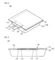
- FIG. 2 is a perspective view illustrating a state after the pouch case is sealed.
- FIG. 3 is a front view of FIG. 2 .
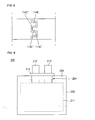
- FIG. 4 is a plan view of FIG. 2 .
- the pouch type lithium secondary battery 100 includes an electrode assembly 110 and a case 120 in which the electrode assembly 110 is sealed and housed.
- the electrode assembly 110 includes a battery unit 111, a cathode tab 112 and an anode tab 113 respectively connected to two electrodes of the battery unit 111.
- the battery unit 111 includes a cathode plate 116, an anode plate 117, and a separator 118 disposed between the cathode plate 116 and the anode plate 117.
- the battery unit 111 is assembled by interposing the separator 118 between the cathode plate 116 and the anode plate 117 and winding the cathode plate 116, the anode plate 117, and the separator 118 together.
- the cathode plate 116 of the battery unit 111 is connected to the cathode tab 112, and the anode plate 117 is connected to the anode tab 113.
- the cathode tab 112 and the anode tab 113 are respectively connected to external terminals (not shown). Protection tapes 114 and 115 are wound on the cathode tab 112 and the anode tab 113 respectively so as to insulate the cathode tab 112 and the anode tab 113 from the case 120.
- the case 120 includes a lower case 122 which houses the battery unit 111, and an upper case 121 which seals an upper surface of the lower case 122.
- a sealing part 123 is formed on three edges about the periphery of the upper and lower cases 121 and 122 at which a seal is formed.
- FIGs. 2 to 4 show the pouch type lithium secondary battery 100 in which the electrode assembly 110 is housed inside the case 120 and the case 120 is closed.
- a stepped part 124 is formed corresponding to a portion at which the cathode tab 112 and the anode tab 113 extend through the sealing part 123 from the inside of the case 120 to the outside of the case 120 between the upper case 121 and the lower case 122 of the case 120.
- the stepped part 124 is formed in the sealing part 123 of the upper case 121 and the lower case 122 corresponding to the portion of the sealing part 123 through which both the cathode tab 112 and the anode tab 113 extend.
- the stepped part 124 is shown as being oppositely formed in a central edge of the three edges about the periphery of the upper and lower cases 121 and 122 in which the seal is formed, the stepped part 124 is not limited thereto. Such a stepped part 124 may be formed in any one of the three edges about the periphery of the upper and lower cases 121 and 122. Further, there need not be only three edges in which the seal is formed such that all of the periphery may be sealed in such a fashion.
- the battery unit 111 is housed inside the lower case 122, and the cathode tab 112 and the anode tab 113 extend outside the lower case 122.
- the cathode tab 112 and the anode tab 113 are wound with the protection tapes 114 and 115 at portions of the cathode tab 112 and the anode tab 113 which contact the upper and lower cases 121 and 122 and are sealed at the sealing part 123.
- the upper case 121 seals the lower case 122.
- the stepped part 124 is formed at the portion where the cathode tab 112 and the anode tab 113 extend outside the lower case 122.
- the cathode tab 112 and the anode tab 113 are located together at the stepped part 124.
- the stepped part 124 is formed by pressing the extending portion of the cathode tab 112 and the anode tab 113 in the sealing part 123 by upper and lower jigs after the sealing part 123 of the upper and lower cases 121 and 122 is sealed.
- the stepped part 124 reduces concentration of pressure on regions corresponding to the cathode tab 112 and anode tab 113, thereby reducing the danger of an electrical short between an externally exposed metal layer of the case 120 and the cathode tab 112 and the anode tab 113.
- a sealing pressure may be increased on the region of the sealing part 123 except for the stepped part 124, thereby improving sealing safety of the sealing part 123.
- width D of the stepped part 124 formed on the sealing part 123 is wider than a distance D1 between the outer edges of the cathode tab 112 and the anode tab 113, thereby preventing an electrical short between the cathode and anode tabs 112 and 113 at the time of forming the stepped part 124.
- the width D of the stepped part 124 is formed so as to be narrower than a distance D2 between outer edges of the protection tapes 114 and 115, thereby allowing an error tolerance with regard to the setting position where the cathode and anode tabs 112 and 113 and the protection tapes 114 and 115 extend from the sealing part 123 and preventing sealing defects.
- the cathode tab 112 is wound with the protection tape 114, and the anode tab 113 is wound with the protection tape 115. That is, the cathode and anode tabs 112 and 113 extend through the sealing part 123 with the protection tapes 114 and 115, and the cathode and anode tabs 112 and 113 are located together in the region of the stepped part 124.
- inside edges of the protection tapes 114 and 115 contact and overlap each other in the stepped part 124.
- the internal region of the stepped part 124 i.e., the region of the stepped part 124 between the cathode tab 112 and the anode tab 113, is sealed by the overlapping protection tapes 114 and 115.
- the protection tapes 114 and 115 may be wound on the cathode and anode tabs 112 and 113 located in the stepped part 124 in various configurations.
- FIGs. 5 to 8 show various modification examples of the type of the protection tape wound on the two electrode tabs.
- FIG. 5 is a view illustrating a state in which inside edges of protection tapes 114A and 115A wound on the cathode tab 112 and the anode 113 tab contact each other.
- FIG. 6 is a view illustrating a state in which inside edges of protection tapes 114B and 115B wound on the cathode tab 112 and the anode 113 tab are spaced apart from each other by a distance d.
- FIG. 7 is a view illustrating a state in which inside edges of protection tapes 114C and 115C wound on the cathode tab 112 and the anode 113 tab are engaged with each other.
- FIG. 8 is a magnification view of 'VIII' portion of FIG. 7 .
- the protection tape 114A and the protection tape 115A surround the cathode tab 112 and the anode tab 113 respectively with their adjacent side edges contacting each other.
- the two adjacent side edges i.e., the inside edges, contact each other in the state that the protection tapes are wound on the electrode tabs.
- the adjacent side edges may be partially overlapped as described above with reference to FIGs. 3 and 4 .
- the protection tapes 114A and 115A seal the internal region of the stepped part 124.
- the protection tapes 114B and 115B surround the cathode tab 112 and the anode tab 113 respectively with their adjacent side edges being spaced with the distance d.
- the distance d is formed as a very fine gap because of the small width between the cathode and anode tabs 112 and 113.
- the stepped part 124 is formed at the sealing portion 123 and thus, the protection tapes 114B and 115B seal the internal region of the stepped part 124.
- a projection part 114C' of the protection tape 114C and a projection part 115C' of the protection tape 115C are formed so as to interlock between the protection tape 114C of the cathode tab 112 and protection tape 115C of the anode tab 113. That is, the projection part 114C' and a groove part 114C" are alternatively formed at an inside edge of the protection tape 114C of the cathode tab 112, and the projection part 115C' and a groove part 115C" are alternatively formed at an inside edge of the protection tape 115C of the anode tab 113.
- the projection part 114C' is inserted into the groove part 115"
- the projection part 115C' is inserted into the groove part 114C".
- a narrow and long path is formed in the region between-adjacent side edges of the protection tape 114C of the cathode tab 112 and protection tape 115C of the anode tab 113 by the combination structure of the interlocking shape.
- the sealing is completed even if only a part of the narrow and long path between the protection tapes 114C and 115C includes the interlocking shape.
- FIG. 9 is a plan view illustrating a pouch type lithium secondary battery 200 according to an exemplary embodiment of the present invention.
- the pouch type lithium secondary battery 200 is constructed so as to surround a cathode tab 212 and an anode tab 213 with one protection tape 214.
- a gap between the cathode and anode tabs 212 and 213 is kept constant.
- FIGs. 10 and 11 show other examples related to an example embodiment of the present invention.
- FIG. 10 is a view illustrating a state in which an electrode tab is attached to a battery unit according to an example embodiment of the present invention.
- FIG. 11 is a sectional view illustrating a pouch battery in which the electrode assembly assembled in FIG. 10 is housed in a pouch case and sealed.
- a pouch type lithium secondary battery 300 is formed by disposing cathode and anode tabs 312 and 313 with one combining member 314 in advance.
- the combining member 314 includes tab holes 314a and 314b passing through the rectangular body of the combining member 314.
- the cathode and anode tabs 312 and 313 respectively extend through the tab holes 314a and 314b.
- the combining member 314 may be made of an insulating material.
- a separator 316 is interposed between a cathode plate 315 and an anode plate 317 and then a battery unit 311 is wound. After winding of the battery unit 311 is finished, the cathode tab 312 is attached to an uncoated part of the cathode plate 315, where an electrode active material is not formed on the cathode plate 315. The anode tab 313 is attached to an uncoated part of the anode plate 316 on which an electrode active material is not formed.
- cathode and anode tabs 312 and 313 are disposed in the combining member 314 in advance, a gap between the cathode and anode tabs 312 and 313 is kept constant. Thus, disruption of the gap between the cathode and anode tabs 312 and 313 does not occur.
- An electrode assembly 310 with the cathode and anode tabs 312 and 313 is received in a lower case 322, and an upper case 321 is sealed to the lower case 322.
- the combining member 314 fixing the cathode and anode tabs 312 and 313 is sealed in the sealing portion 323.
- One stepped part 324 is formed in the sealing portion 323, and thus, the combining member 314 is sealed in an internal region of the stepped part 324.
- the cathode and anode tabs 312 and 313 of the electrode assembly 310 extend in parallel through the sealing portion 323 of the case 320 during the sealing process of the case 320. As such, the cathode and anode tabs 312 and 313 are attached to an outermost part of the battery unit 311. Accordingly, there is an advantage in that it is easy to control positions of the cathode and anode tabs 312 and 313 when the electrode assembly 310 is received in the lower case 321.
- workability of attaching the electrode tab to the electrode plate is improved in the short width type battery.
- sealing is improved at the sealing portion of the electrode tab and case in sealing of the upper and lower cases. Further, it is easy to control the position of the electrode tabs in the state in which the electrode assembly is housed in the case.
- the pouch type lithium secondary battery according to one or more preferred embodiments of the present invention produces the following and/or other effects: First, the quality of the sealing portion of the pouch case where the electrode tabs extend is stabilized, thereby improving reliability of the secondary battery. Second, workability of the assembling and sealing processes of the battery is improved, thereby improving efficiency of the manufacturing process.
Landscapes
- Chemical & Material Sciences (AREA)
- Chemical Kinetics & Catalysis (AREA)
- Electrochemistry (AREA)
- General Chemical & Material Sciences (AREA)
- Engineering & Computer Science (AREA)
- Manufacturing & Machinery (AREA)
- Secondary Cells (AREA)
- Connection Of Batteries Or Terminals (AREA)
- Sealing Battery Cases Or Jackets (AREA)
Abstract
Description
- Aspects of the present invention relate to a pouch type lithium secondary battery, and more particularly, to a pouch type lithium secondary battery that can minimize a size of a cell.
- Generally, a lithium secondary battery uses a non-aqueous electrolyte because the lithium actively reacts with water. The electrolyte may be a solid polymer containing lithium salts or a liquid in which the lithium salts are dissociated from an organic solvent.
- The lithium secondary battery can be divided according to the kind of electrolyte used, i.e., lithium metal and lithium ion batteries, both of which use a liquid electrolyte, and lithium ion polymer batteries, which use a solid polymer electrolyte. The lithium ion polymer battery can be a completely solid type lithium ion polymer battery containing no organic electrolyte or a lithium ion polymer battery using a gel type polymer electrolyte containing an organic electrolyte.
- In the lithium ion polymer battery, a multi-layer film pouch can be used instead of a metal can as used in the lithium metal and lithium ion batteries. The multi-layer film pouch may be formed of a metal foil and at least one polymer film covering the foil. When such a multi-layer film pouch is used, the weight of the secondary cell can be greatly reduced compared to the use of a metal can. Aluminum is usually used as the metal forming the foil in the multi-layer film pouch. The polymer film that forms an inner layer of the pouch film protects the metal foil from the electrolyte and prevents an electrical short between electrode tabs.
- The pouch type lithium secondary battery may be formed by sealing an electrode assembly, which includes a cathode, a separator, and an anode stacked and/or wound, in a pouch. Then, the sealed pouch type bare cell is manufactured by bonding upper and lower pouch films to open peripheral parts by heating.
- In the pouch type bare cell, generally two electrode tabs connected to the electrode assembly extend from the electrode assembly to the outside of the pouch type bare cell. A protection tape is provided to a portion where the two electrode tabs and pouch contact, thereby keeping the two electrode tabs insulated from the pouch during sealing. A stepped part is formed for each electrode tab. The stepped part has a width narrower than that of the protection tape at a sealing portion where the protection tape is provided in the pouch. The sealing pressure is substantially applied to the peripheral region of the stepped part and, in the stepped part, a region corresponding to the electrode tab is under less pressure. Thus, the possibility of the electrical short between the metal layer of the pouch and the electrode tabs becomes low , thereby improving the safety of the sealing.
- As the size of the pouch type lithium secondary battery is greatly reduced, the width of the battery in a longitudinal direction of an extending surface of the electrode tab becomes gradually shorter. In a battery having a short width, the gap between the extending electrode tabs becomes very narrow.
- In a battery having a narrow gap between the electrode tabs, it is difficult to exactly set the electrode tab at a position where the stepped part is formed during a sealing process. Accordingly, when the electrode tab is not properly set at the stepped part-forming position, the electrode tab is electrically shorted or defects in sealing may occur.
- Particularly, in a battery having a short width between the electrode tabs, it is difficult to weld the electrode tabs to an electrode plate and maintain a proper seal around the electrode tab while reducing distribution of gaps between the electrode tabs.
- According to aspects of the present invention, the reliability of product having a pouch type lithium secondary battery may be improved by stabilizing the quality of the sealing portion of the pouch case where electrode tabs extend.
- According to aspects of the present invention, the efficiency of a manufacturing process of a pouch type lithium secondary battery may be improved by improving the workability of the assembling and sealing processes of the battery.
- According to an aspect of the present invention, there is provided a pouch type lithium secondary battery, comprising: an electrode assembly comprising electrode tabs respectively connected to two electrodes, the two electrodes having different polarities; and a case to house the electrode assembly such that the electrode tabs extend to the outside of the case, wherein one stepped part through which the two electrode tabs extend is formed in a sealing portion of the case.
- According to a preferred embodiment of the present invention, the two electrode tabs may be surrounded by an insulating member; the two electrode tabs and the insulating member may be located in an internal region of the stepped part; and outer portions of the insulating member may be formed in the sealing portion of the case outside of the stepped part.
- According to preferred embodiment of the present invention, each of the two electrode tabs may be respectively surrounded by an insulating member.
- Preferably, the two electrode tabs may be surrounded by one insulating member.
- In a preferred embodiment, the insulating member may be a tape.
- According to a further preferred embodiment of the present invention, adjacent side edges of each of the insulating members between the two electrode tabs may overlap in the region of the stepped part.
- Preferably, the insulating members may be respectively wound on the two electrode tabs such that adjacent side edges contact; or, the insulating members may be wound on the two electrode tabs with their adjacent side edges being spaced apart; or, the insulating members may be wound on the two electrode tabs with their adjacent side edges being interlocked.
- According to a preferred embodiment of the present invention, the two electrode tabs may extend through one combining member; the combining member may include tab holes through which the two electrode tabs extend; and the combining member may be made of an insulating material.
- Preferably, the two electrode tabs may be respectively attached to uncoated parts of two electrode plates of the electrode assembly.
- Additional aspects and/or advantages of the invention will be set forth in part in the description which follows and, in part, will be obvious from the description, or may be learned by practice of the invention.
- These and/or other aspects and advantages of the invention will become apparent and more readily appreciated from the following description of preferred embodiments, taken in conjunction with the accompanying drawings of which:
-
FIG. 1 is an exploded perspective view illustrating a state before a pouch type lithium secondary battery is sealed; -
FIG. 2 is a perspective view illustrating a state after a pouch type lithium secondary battery according to an exemplary embodiment of the present invention is sealed; -
FIG. 3 is a front view ofFIG. 2 ; -
FIG. 4 is a plan view ofFIG. 2 ; -
FIG. 5 is a view illustrating a state in which side edges of the protection tape wound on the electrode tab are in contact with each other; -
FIG. 6 is a view illustrating a state in which side edges of the protection tape wound on the electrode tab are spaced from each other; -
FIG. 7 is a view illustrating a state in which side edges of the protection tape wound on the electrode tabs are engaged with each other; -
FIG. 8 is a magnification view of 'VIII' portion ofFIG. 7 ; -
FIG. 9 is a plan view illustrating a pouch type lithium secondary battery according to an exemplary embodiment of the present invention; -
FIG. 10 is a view illustrating a state in which an electrode tab is attached to an electrode assembly; and -
FIG. 11 is a sectional view illustrating a state in which the electrode assembly is housed in a pouch case and sealed. - Reference will now be made in detail to the present embodiments of the present invention, examples of which are illustrated in the accompanying drawings, wherein like reference numerals refer to the like elements throughout. The preferred embodiments are described below in order to explain the present invention by referring to the figures.
-
FIGs. 1 to 4 show a pouch type lithium secondary battery according to an exemplary embodiment of the present invention.FIG. 1 is an exploded perspective view illustrating a state before a pouch case is sealed in a pouch type lithium secondary battery.FIG. 2 is a perspective view illustrating a state after the pouch case is sealed.FIG. 3 is a front view ofFIG. 2 .FIG. 4 is a plan view ofFIG. 2 . - Referring to
FIG. 1 , the pouch type lithiumsecondary battery 100 includes anelectrode assembly 110 and acase 120 in which theelectrode assembly 110 is sealed and housed. Theelectrode assembly 110 includes abattery unit 111, acathode tab 112 and ananode tab 113 respectively connected to two electrodes of thebattery unit 111. - The
battery unit 111 includes acathode plate 116, ananode plate 117, and aseparator 118 disposed between thecathode plate 116 and theanode plate 117. Thebattery unit 111 is assembled by interposing theseparator 118 between thecathode plate 116 and theanode plate 117 and winding thecathode plate 116, theanode plate 117, and theseparator 118 together. Thecathode plate 116 of thebattery unit 111 is connected to thecathode tab 112, and theanode plate 117 is connected to theanode tab 113. Thecathode tab 112 and theanode tab 113 are respectively connected to external terminals (not shown).Protection tapes cathode tab 112 and theanode tab 113 respectively so as to insulate thecathode tab 112 and theanode tab 113 from thecase 120. - The
case 120 includes alower case 122 which houses thebattery unit 111, and anupper case 121 which seals an upper surface of thelower case 122. A sealingpart 123 is formed on three edges about the periphery of the upper andlower cases -
FIGs. 2 to 4 show the pouch type lithiumsecondary battery 100 in which theelectrode assembly 110 is housed inside thecase 120 and thecase 120 is closed. Referring toFIGs. 2 to 4 , in the pouch type lithium secondary battery, a steppedpart 124 is formed corresponding to a portion at which thecathode tab 112 and theanode tab 113 extend through the sealingpart 123 from the inside of thecase 120 to the outside of thecase 120 between theupper case 121 and thelower case 122 of thecase 120. The steppedpart 124 is formed in the sealingpart 123 of theupper case 121 and thelower case 122 corresponding to the portion of the sealingpart 123 through which both thecathode tab 112 and theanode tab 113 extend. Although the steppedpart 124 is shown as being oppositely formed in a central edge of the three edges about the periphery of the upper andlower cases part 124 is not limited thereto. Such a steppedpart 124 may be formed in any one of the three edges about the periphery of the upper andlower cases - In the pouch type lithium
secondary battery 100, thebattery unit 111 is housed inside thelower case 122, and thecathode tab 112 and theanode tab 113 extend outside thelower case 122. Thecathode tab 112 and theanode tab 113 are wound with theprotection tapes cathode tab 112 and theanode tab 113 which contact the upper andlower cases part 123. Thus, theupper case 121 seals thelower case 122. - In the sealing
part 123 of thecase 120 as described above, the steppedpart 124 is formed at the portion where thecathode tab 112 and theanode tab 113 extend outside thelower case 122. Thecathode tab 112 and theanode tab 113 are located together at the steppedpart 124. The steppedpart 124 is formed by pressing the extending portion of thecathode tab 112 and theanode tab 113 in the sealingpart 123 by upper and lower jigs after the sealingpart 123 of the upper andlower cases - The stepped
part 124, where the cathode andanode tabs cathode tab 112 andanode tab 113, thereby reducing the danger of an electrical short between an externally exposed metal layer of thecase 120 and thecathode tab 112 and theanode tab 113. In addition, a sealing pressure may be increased on the region of the sealingpart 123 except for the steppedpart 124, thereby improving sealing safety of the sealingpart 123. - With specific reference to
FIG. 4 , width D of the steppedpart 124 formed on the sealingpart 123 is wider than a distance D1 between the outer edges of thecathode tab 112 and theanode tab 113, thereby preventing an electrical short between the cathode andanode tabs part 124. - The width D of the stepped
part 124 is formed so as to be narrower than a distance D2 between outer edges of theprotection tapes anode tabs protection tapes part 123 and preventing sealing defects. - Referring to
FIGs. 2 to 4 , in the pouch type lithiumsecondary battery 100, thecathode tab 112 is wound with theprotection tape 114, and theanode tab 113 is wound with theprotection tape 115. That is, the cathode andanode tabs part 123 with theprotection tapes anode tabs part 124. - With specific reference to
FIGs. 3 and4 , inside edges of theprotection tapes part 124. The internal region of the steppedpart 124, i.e., the region of the steppedpart 124 between thecathode tab 112 and theanode tab 113, is sealed by the overlappingprotection tapes - The
protection tapes anode tabs part 124 in various configurations.FIGs. 5 to 8 show various modification examples of the type of the protection tape wound on the two electrode tabs. -
FIG. 5 is a view illustrating a state in which inside edges ofprotection tapes cathode tab 112 and theanode 113 tab contact each other.FIG. 6 is a view illustrating a state in which inside edges ofprotection tapes cathode tab 112 and theanode 113 tab are spaced apart from each other by a distance d.FIG. 7 is a view illustrating a state in which inside edges ofprotection tapes cathode tab 112 and theanode 113 tab are engaged with each other.FIG. 8 is a magnification view of 'VIII' portion ofFIG. 7 . - Referring to
FIG. 5 , theprotection tape 114A and theprotection tape 115A surround thecathode tab 112 and theanode tab 113 respectively with their adjacent side edges contacting each other. The two adjacent side edges, i.e., the inside edges, contact each other in the state that the protection tapes are wound on the electrode tabs. Alternatively, the adjacent side edges may be partially overlapped as described above with reference toFIGs. 3 and4 . When the steppedpart 124 is formed on the sealingpart 123 in the state in which theprotection tape 114A andprotection tape 115A contact each other or are partially overlapped, theprotection tapes part 124. - Referring to
FIG. 6 illustrating another modification example, theprotection tapes cathode tab 112 and theanode tab 113 respectively with their adjacent side edges being spaced with the distance d. The distance d is formed as a very fine gap because of the small width between the cathode andanode tabs protection tapes part 124 is formed at the sealingportion 123 and thus, theprotection tapes part 124. - Referring to
FIGs. 7 and8 illustrating still another modification example, aprojection part 114C' of theprotection tape 114C and aprojection part 115C' of theprotection tape 115C are formed so as to interlock between theprotection tape 114C of thecathode tab 112 andprotection tape 115C of theanode tab 113. That is, theprojection part 114C' and agroove part 114C" are alternatively formed at an inside edge of theprotection tape 114C of thecathode tab 112, and theprojection part 115C' and agroove part 115C" are alternatively formed at an inside edge of theprotection tape 115C of theanode tab 113. Further, theprojection part 114C' is inserted into thegroove part 115", and theprojection part 115C' is inserted into thegroove part 114C". Thus, two facing side edges of theprotection tapes - A narrow and long path is formed in the region between-adjacent side edges of the
protection tape 114C of thecathode tab 112 andprotection tape 115C of theanode tab 113 by the combination structure of the interlocking shape. Thus, when sealing process is performed, the sealing is completed even if only a part of the narrow and long path between theprotection tapes -
FIG. 9 is a plan view illustrating a pouch type lithiumsecondary battery 200 according to an exemplary embodiment of the present invention. The pouch type lithiumsecondary battery 200 is constructed so as to surround acathode tab 212 and ananode tab 213 with oneprotection tape 214. When the cathode andanode tabs protection tape 214, a gap between the cathode andanode tabs electrode tabs portion 223 of acase 220. Further, sealing stability is improved in an internal region of a steppedpart 224 formed at the sealingportion 223 of thecase 220. -
FIGs. 10 and 11 show other examples related to an example embodiment of the present invention. -
FIG. 10 is a view illustrating a state in which an electrode tab is attached to a battery unit according to an example embodiment of the present invention.FIG. 11 is a sectional view illustrating a pouch battery in which the electrode assembly assembled inFIG. 10 is housed in a pouch case and sealed. - As shown in
FIGs. 10 and 11 , a pouch type lithiumsecondary battery 300 is formed by disposing cathode andanode tabs member 314 in advance. The combiningmember 314 includestab holes member 314. The cathode andanode tabs member 314 may be made of an insulating material. - An assembling process of the pouch type lithium
secondary battery 300 will be explained below. First, aseparator 316 is interposed between acathode plate 315 and ananode plate 317 and then abattery unit 311 is wound. After winding of thebattery unit 311 is finished, thecathode tab 312 is attached to an uncoated part of thecathode plate 315, where an electrode active material is not formed on thecathode plate 315. Theanode tab 313 is attached to an uncoated part of theanode plate 316 on which an electrode active material is not formed. Because the cathode andanode tabs member 314 in advance, a gap between the cathode andanode tabs anode tabs - An
electrode assembly 310 with the cathode andanode tabs lower case 322, and anupper case 321 is sealed to thelower case 322. The combiningmember 314 fixing the cathode andanode tabs portion 323. One steppedpart 324 is formed in the sealingportion 323, and thus, the combiningmember 314 is sealed in an internal region of the steppedpart 324. - The cathode and
anode tabs electrode assembly 310 extend in parallel through the sealingportion 323 of thecase 320 during the sealing process of thecase 320. As such, the cathode andanode tabs battery unit 311. Accordingly, there is an advantage in that it is easy to control positions of the cathode andanode tabs electrode assembly 310 is received in thelower case 321. - According to aspects of the present invention, workability of attaching the electrode tab to the electrode plate is improved in the short width type battery. In addition, sealing is improved at the sealing portion of the electrode tab and case in sealing of the upper and lower cases. Further, it is easy to control the position of the electrode tabs in the state in which the electrode assembly is housed in the case.
- As described above, the pouch type lithium secondary battery according to one or more preferred embodiments of the present invention produces the following and/or other effects: First, the quality of the sealing portion of the pouch case where the electrode tabs extend is stabilized, thereby improving reliability of the secondary battery. Second, workability of the assembling and sealing processes of the battery is improved, thereby improving efficiency of the manufacturing process.
- Although a few embodiments of the present invention have been shown and described, it would be appreciated by those skilled in the art that changes may be made in this embodiment without departing from the invention.
Claims (15)
- A pouch type lithium secondary battery, comprising:an electrode assembly comprising electrode tabs respectively connected to two electrodes, the two electrodes having different polarities;a case to house the electrode assembly such that the electrode tabs extend to the outside of the case; andone stepped part through which the two electrode tabs extend formed in a sealing portion of the case.
- The pouch type lithium secondary battery of claim 1, wherein the two electrode tabs are surrounded by an insulating member.
- The pouch type lithium secondary battery of claim 2, wherein the two electrode tabs and the insulating member are located in an internal region of the stepped part.
- The pouch type lithium secondary battery of any one of claims 2 or 3, wherein outer portions of the insulating member are formed in the sealing portion of the case outside of the stepped part.
- The pouch type lithium secondary battery of claim 1, wherein the two electrode tabs are respectively surrounded by insulating members.
- The pouch type lithium secondary battery of claim 5, wherein adjacent side edges of each of the insulating members between the two electrode tabs overlap.
- The pouch type lithium secondary battery of any one of claims 5 or 6, wherein the insulating members are respectively wound on the two electrode tabs such that the adjacent side edges contact.
- The pouch type lithium secondary battery of claim 5, wherein the insulating members are respectively wound on the two electrode tabs such that the adjacent side edges do not contact.
- The pouch type lithium secondary battery of claim 5, wherein the insulating members are respectively wound on the two electrode tabs such that the adjacent side edges are interlocked.
- The pouch type lithium secondary battery of any one of claims 2 to 4, wherein the two electrode tabs are surrounded by one insulating member.
- The pouch type lithium secondary battery of claim 2, wherein the insulating member is a tape.
- The pouch type lithium secondary battery of claim 1, wherein the two electrode tabs extend through one combining member.
- The pouch type lithium secondary battery of claim 12, wherein the combining member includes tab holes through which the two electrode tabs extend.
- The pouch type lithium secondary battery of any one of claims 12 or 13, wherein the combining member is an insulating material.
- The pouch type lithium secondary battery of any one of claims 12 to 14, wherein the two electrode tabs are respectively attached to uncoated portions of two electrode plates of the electrode assembly.
Applications Claiming Priority (1)
| Application Number | Priority Date | Filing Date | Title |
|---|---|---|---|
| KR1020070072187A KR100917734B1 (en) | 2007-07-19 | 2007-07-19 | Pouch Type Lithium Secondary Battery |
Publications (2)
| Publication Number | Publication Date |
|---|---|
| EP2017908A1 true EP2017908A1 (en) | 2009-01-21 |
| EP2017908B1 EP2017908B1 (en) | 2013-07-24 |
Family
ID=39798080
Family Applications (1)
| Application Number | Title | Priority Date | Filing Date |
|---|---|---|---|
| EP08252219.4A Active EP2017908B1 (en) | 2007-07-19 | 2008-06-27 | Pouch type lithium secondary battery |
Country Status (5)
| Country | Link |
|---|---|
| US (2) | US8313857B2 (en) |
| EP (1) | EP2017908B1 (en) |
| JP (1) | JP5512088B2 (en) |
| KR (1) | KR100917734B1 (en) |
| CN (1) | CN101350433B (en) |
Cited By (4)
| Publication number | Priority date | Publication date | Assignee | Title |
|---|---|---|---|---|
| US8455124B2 (en) | 2009-09-30 | 2013-06-04 | Samsung Sdi Co., Ltd. | Secondary battery and method of fabricating the same |
| WO2019034852A1 (en) * | 2017-08-18 | 2019-02-21 | Agm Batteries Limited | Pouch battery or cell |
| EP3726604A1 (en) * | 2019-04-15 | 2020-10-21 | SK Innovation Co., Ltd. | Superwide pouch type secondary battery with double tabs |
| US12573723B2 (en) | 2016-06-22 | 2026-03-10 | Semiconductor Energy Laboratory Co., Ltd. | Battery and manufacturing method of the same |
Families Citing this family (24)
| Publication number | Priority date | Publication date | Assignee | Title |
|---|---|---|---|---|
| JP5793788B2 (en) * | 2009-05-21 | 2015-10-14 | エルジー ケム. エルティーディ. | Water-resistant pouch-type secondary battery |
| DE102009037849A1 (en) * | 2009-08-18 | 2011-02-24 | Li-Tec Battery Gmbh | Method for producing an electrochemical cell |
| KR101106429B1 (en) | 2009-12-01 | 2012-01-18 | 삼성에스디아이 주식회사 | Secondary battery |
| US9077027B2 (en) | 2010-03-04 | 2015-07-07 | Samsung Sdi Co., Ltd. | Electrode assembly and secondary battery using the same |
| JP2011216202A (en) * | 2010-03-31 | 2011-10-27 | Murata Mfg Co Ltd | Power storage device |
| JP5589534B2 (en) * | 2010-04-28 | 2014-09-17 | 日産自動車株式会社 | Flat battery |
| US20110311862A1 (en) * | 2010-06-21 | 2011-12-22 | Samsung Sdi Co., Ltd. | Secondary battery |
| WO2012026705A2 (en) * | 2010-08-23 | 2012-03-01 | 주식회사 엘지화학 | Improved jelly-roll structure, and secondary battery having same |
| KR101369325B1 (en) | 2011-06-30 | 2014-03-04 | 주식회사 엘지화학 | Secondary electric cell with enhanced contact resistance |
| DE102011110007A1 (en) | 2011-08-11 | 2013-02-14 | Li-Tec Battery Gmbh | Electrochemical energy storage e.g. galvanic cell, for use in motor car, has electrode assembly including sequence of electrodes, where arrester tabs of current collectors protruded from electrode assembly are combined between two of arms |
| WO2013020677A2 (en) | 2011-08-11 | 2013-02-14 | Li-Tec Battery Gmbh | Electrochemical energy store and process for the production thereof |
| US9005786B2 (en) * | 2011-10-21 | 2015-04-14 | GM Global Technology Operations LLC | Integrated cell voltage sense line fusing |
| KR101547403B1 (en) * | 2013-01-11 | 2015-08-25 | 주식회사 엘지화학 | Secondary battery comprising unified positive lead and negative lead and the method for preparing thereof |
| KR102409800B1 (en) | 2014-05-29 | 2022-06-16 | 가부시키가이샤 한도오따이 에네루기 켄큐쇼 | Secondary battery and electronic device |
| KR101769106B1 (en) | 2014-10-31 | 2017-08-17 | 주식회사 엘지화학 | A pouch type secondary battery and a electrode lead assembly applied for the same |
| JP6497994B2 (en) * | 2015-03-17 | 2019-04-10 | セイコーインスツル株式会社 | Method for producing electrochemical cell |
| KR101984265B1 (en) * | 2015-07-03 | 2019-05-30 | 주식회사 엘지화학 | Pouch type secondary battery and method of fabricating the same |
| US10141550B2 (en) | 2016-10-20 | 2018-11-27 | Ford Global Technologies, Llc | Pouch battery cell assembly for traction battery |
| US20190020000A1 (en) * | 2017-07-11 | 2019-01-17 | Apple Inc. | Battery cell tabs with a unitary seal |
| KR102878035B1 (en) * | 2019-04-15 | 2025-10-29 | 에스케이온 주식회사 | Superwide Pouch Type Secondary Battery with Double Taps |
| CN110085797B (en) * | 2019-05-23 | 2022-04-19 | 西安瑟福能源科技有限公司 | Polymer lithium ion battery connected tab and manufacturing and using methods thereof |
| US11631866B2 (en) | 2020-06-08 | 2023-04-18 | Saft America | Lithium-ion primary pouch battery |
| JP2023523113A (en) * | 2021-03-31 | 2023-06-02 | 寧徳新能源科技有限公司 | battery |
| CN113690550A (en) * | 2021-07-14 | 2021-11-23 | 东莞新能源科技有限公司 | Cells, batteries and electrical equipment |
Citations (7)
| Publication number | Priority date | Publication date | Assignee | Title |
|---|---|---|---|---|
| US4278744A (en) * | 1975-12-19 | 1981-07-14 | Duracell International Inc. | Expandable casing for electro-chemical cells |
| EP0975031A1 (en) * | 1998-02-05 | 2000-01-26 | Dai Nippon Printing Co., Ltd. | Sheet for cell case and cell device |
| EP1043785A1 (en) * | 1998-10-30 | 2000-10-11 | Sony Corporation | Non-aqueous electrolytic cell and production method therefor |
| EP1202371A1 (en) * | 1999-03-26 | 2002-05-02 | Matsushita Electric Industrial Co., Ltd. | Laminate sheath type battery |
| US20030054241A1 (en) * | 2001-01-18 | 2003-03-20 | Rikiya Yamashita | Battery device and lead wire film |
| US20040033416A1 (en) * | 2002-06-29 | 2004-02-19 | Sang-Bum Kim | Pouch type secondary battery |
| WO2007055479A1 (en) * | 2005-11-08 | 2007-05-18 | Lg Chem, Ltd. | Secondary battery with advanced safety |
Family Cites Families (11)
| Publication number | Priority date | Publication date | Assignee | Title |
|---|---|---|---|---|
| US4728744A (en) * | 1985-10-02 | 1988-03-01 | Exxon Chemical Patents Inc. | Catalysts for preparation of aromatic carboxylic anhydrides |
| WO2000028607A1 (en) * | 1998-11-06 | 2000-05-18 | Japan Storage Battery Co., Ltd. | Non-aqueous electrolytic secondary cell |
| JP4193271B2 (en) * | 1999-03-12 | 2008-12-10 | ソニー株式会社 | Solid electrolyte battery |
| CA2368006C (en) | 2000-01-26 | 2008-12-30 | Dai Nippon Printing Co., Ltd. | Heat-sealing machine, heat-sealing method, embossing method, work pressing machine and workpiece |
| JP2001297738A (en) | 2000-04-17 | 2001-10-26 | Yuasa Corp | Sealed battery and method of manufacturing sealed battery |
| JP2002190283A (en) * | 2000-12-21 | 2002-07-05 | At Battery:Kk | Method of manufacturing thin secondary battery and thin secondary battery |
| KR20040054128A (en) * | 2002-12-17 | 2004-06-25 | 삼성에스디아이 주식회사 | Pouched-type lithium secondary battery |
| KR20050020357A (en) * | 2003-08-22 | 2005-03-04 | 삼성에스디아이 주식회사 | Pouch case and pouched type secondary battery comprising the same |
| JP4443248B2 (en) | 2004-01-28 | 2010-03-31 | 三洋電機株式会社 | Manufacturing method of laminated battery |
| KR100601549B1 (en) * | 2004-06-28 | 2006-07-19 | 삼성에스디아이 주식회사 | Pouch Type Lithium Secondary Battery |
| JP4718812B2 (en) | 2004-09-06 | 2011-07-06 | Necエナジーデバイス株式会社 | Secondary battery pack |
-
2007
- 2007-07-19 KR KR1020070072187A patent/KR100917734B1/en active Active
-
2008
- 2008-02-26 JP JP2008045021A patent/JP5512088B2/en active Active
- 2008-03-25 US US12/054,752 patent/US8313857B2/en active Active
- 2008-06-27 EP EP08252219.4A patent/EP2017908B1/en active Active
- 2008-07-04 CN CN2008101330018A patent/CN101350433B/en active Active
-
2012
- 2012-10-18 US US13/655,253 patent/US8623547B2/en active Active
Patent Citations (7)
| Publication number | Priority date | Publication date | Assignee | Title |
|---|---|---|---|---|
| US4278744A (en) * | 1975-12-19 | 1981-07-14 | Duracell International Inc. | Expandable casing for electro-chemical cells |
| EP0975031A1 (en) * | 1998-02-05 | 2000-01-26 | Dai Nippon Printing Co., Ltd. | Sheet for cell case and cell device |
| EP1043785A1 (en) * | 1998-10-30 | 2000-10-11 | Sony Corporation | Non-aqueous electrolytic cell and production method therefor |
| EP1202371A1 (en) * | 1999-03-26 | 2002-05-02 | Matsushita Electric Industrial Co., Ltd. | Laminate sheath type battery |
| US20030054241A1 (en) * | 2001-01-18 | 2003-03-20 | Rikiya Yamashita | Battery device and lead wire film |
| US20040033416A1 (en) * | 2002-06-29 | 2004-02-19 | Sang-Bum Kim | Pouch type secondary battery |
| WO2007055479A1 (en) * | 2005-11-08 | 2007-05-18 | Lg Chem, Ltd. | Secondary battery with advanced safety |
Cited By (7)
| Publication number | Priority date | Publication date | Assignee | Title |
|---|---|---|---|---|
| US8455124B2 (en) | 2009-09-30 | 2013-06-04 | Samsung Sdi Co., Ltd. | Secondary battery and method of fabricating the same |
| US12573723B2 (en) | 2016-06-22 | 2026-03-10 | Semiconductor Energy Laboratory Co., Ltd. | Battery and manufacturing method of the same |
| WO2019034852A1 (en) * | 2017-08-18 | 2019-02-21 | Agm Batteries Limited | Pouch battery or cell |
| GB2579964A (en) * | 2017-08-18 | 2020-07-08 | Agm Batteries Ltd | Pouch battery or cell |
| GB2579964B (en) * | 2017-08-18 | 2023-01-11 | Amte Power Plc | Pouch battery or cell |
| EP3726604A1 (en) * | 2019-04-15 | 2020-10-21 | SK Innovation Co., Ltd. | Superwide pouch type secondary battery with double tabs |
| US11276873B2 (en) | 2019-04-15 | 2022-03-15 | Sk Innovation Co., Ltd. | Superwide pouch type secondary battery with double tabs |
Also Published As
| Publication number | Publication date |
|---|---|
| US20090023062A1 (en) | 2009-01-22 |
| US8313857B2 (en) | 2012-11-20 |
| CN101350433B (en) | 2012-01-18 |
| KR100917734B1 (en) | 2009-09-21 |
| US8623547B2 (en) | 2014-01-07 |
| JP5512088B2 (en) | 2014-06-04 |
| KR20090008869A (en) | 2009-01-22 |
| EP2017908B1 (en) | 2013-07-24 |
| US20130040192A1 (en) | 2013-02-14 |
| JP2009026739A (en) | 2009-02-05 |
| CN101350433A (en) | 2009-01-21 |
Similar Documents
| Publication | Publication Date | Title |
|---|---|---|
| EP2017908B1 (en) | Pouch type lithium secondary battery | |
| EP3503250B1 (en) | Rechargeable battery | |
| EP3514858B1 (en) | Secondary battery | |
| US20250046969A1 (en) | Secondary battery | |
| KR20200108719A (en) | Secondary Battery | |
| US20170250388A1 (en) | Prismatic secondary battery | |
| US20200091492A1 (en) | Secondary battery | |
| US20120148884A1 (en) | Secondary battery | |
| KR20170060941A (en) | Rechargeable battery | |
| KR20150046946A (en) | Rechargeable secondary battery | |
| US20240274936A1 (en) | Sealed battery | |
| US20230343992A1 (en) | Secondary battery | |
| KR20180031444A (en) | Secondary battery | |
| KR102512060B1 (en) | Rechargeable battery | |
| EP3477730B1 (en) | Secondary battery | |
| EP4213280B1 (en) | Secondary battery | |
| US20240396187A1 (en) | Secondary battery and battery module | |
| KR20220130426A (en) | secondary battery | |
| KR100530156B1 (en) | Pouch type lithium secondary battery | |
| KR20170022372A (en) | Secondary Battery And Fabricating Method Thereof | |
| KR20180108282A (en) | Rechargeable battery | |
| EP4531175A1 (en) | Secondary battery | |
| US20240396189A1 (en) | Secondary battery | |
| US10505217B2 (en) | Rechargeable battery | |
| JP2018181606A (en) | Electrochemical cell |
Legal Events
| Date | Code | Title | Description |
|---|---|---|---|
| PUAI | Public reference made under article 153(3) epc to a published international application that has entered the european phase |
Free format text: ORIGINAL CODE: 0009012 |
|
| 17P | Request for examination filed |
Effective date: 20080703 |
|
| AK | Designated contracting states |
Kind code of ref document: A1 Designated state(s): AT BE BG CH CY CZ DE DK EE ES FI FR GB GR HR HU IE IS IT LI LT LU LV MC MT NL NO PL PT RO SE SI SK TR |
|
| AX | Request for extension of the european patent |
Extension state: AL BA MK RS |
|
| AKX | Designation fees paid |
Designated state(s): DE FR GB HU |
|
| 17Q | First examination report despatched |
Effective date: 20100817 |
|
| REG | Reference to a national code |
Ref country code: DE Ref legal event code: R079 Ref document number: 602008026215 Country of ref document: DE Free format text: PREVIOUS MAIN CLASS: H01M0002020000 Ipc: H01M0010052000 |
|
| RIC1 | Information provided on ipc code assigned before grant |
Ipc: H01M 2/06 20060101ALI20121018BHEP Ipc: H01M 10/052 20100101AFI20121018BHEP Ipc: H01M 2/30 20060101ALI20121018BHEP Ipc: H01M 10/04 20060101ALI20121018BHEP Ipc: H01M 2/02 20060101ALI20121018BHEP |
|
| GRAP | Despatch of communication of intention to grant a patent |
Free format text: ORIGINAL CODE: EPIDOSNIGR1 |
|
| GRAS | Grant fee paid |
Free format text: ORIGINAL CODE: EPIDOSNIGR3 |
|
| GRAA | (expected) grant |
Free format text: ORIGINAL CODE: 0009210 |
|
| AK | Designated contracting states |
Kind code of ref document: B1 Designated state(s): DE FR GB HU |
|
| REG | Reference to a national code |
Ref country code: GB Ref legal event code: FG4D |
|
| REG | Reference to a national code |
Ref country code: DE Ref legal event code: R096 Ref document number: 602008026215 Country of ref document: DE Effective date: 20130919 |
|
| PLBE | No opposition filed within time limit |
Free format text: ORIGINAL CODE: 0009261 |
|
| STAA | Information on the status of an ep patent application or granted ep patent |
Free format text: STATUS: NO OPPOSITION FILED WITHIN TIME LIMIT |
|
| 26N | No opposition filed |
Effective date: 20140425 |
|
| REG | Reference to a national code |
Ref country code: DE Ref legal event code: R097 Ref document number: 602008026215 Country of ref document: DE Effective date: 20140425 |
|
| REG | Reference to a national code |
Ref country code: FR Ref legal event code: PLFP Year of fee payment: 9 |
|
| PG25 | Lapsed in a contracting state [announced via postgrant information from national office to epo] |
Ref country code: HU Free format text: LAPSE BECAUSE OF FAILURE TO SUBMIT A TRANSLATION OF THE DESCRIPTION OR TO PAY THE FEE WITHIN THE PRESCRIBED TIME-LIMIT; INVALID AB INITIO Effective date: 20080627 |
|
| REG | Reference to a national code |
Ref country code: FR Ref legal event code: PLFP Year of fee payment: 10 |
|
| REG | Reference to a national code |
Ref country code: FR Ref legal event code: PLFP Year of fee payment: 11 |
|
| P01 | Opt-out of the competence of the unified patent court (upc) registered |
Effective date: 20230528 |
|
| PGFP | Annual fee paid to national office [announced via postgrant information from national office to epo] |
Ref country code: DE Payment date: 20250604 Year of fee payment: 18 |
|
| PGFP | Annual fee paid to national office [announced via postgrant information from national office to epo] |
Ref country code: GB Payment date: 20250529 Year of fee payment: 18 |
|
| PGFP | Annual fee paid to national office [announced via postgrant information from national office to epo] |
Ref country code: FR Payment date: 20250610 Year of fee payment: 18 |