EP2017562A1 - Plate heat exchanger gasket - Google Patents
Plate heat exchanger gasket Download PDFInfo
- Publication number
- EP2017562A1 EP2017562A1 EP07014018A EP07014018A EP2017562A1 EP 2017562 A1 EP2017562 A1 EP 2017562A1 EP 07014018 A EP07014018 A EP 07014018A EP 07014018 A EP07014018 A EP 07014018A EP 2017562 A1 EP2017562 A1 EP 2017562A1
- Authority
- EP
- European Patent Office
- Prior art keywords
- heat exchanger
- gasket
- plate heat
- connection
- connection end
- Prior art date
- Legal status (The legal status is an assumption and is not a legal conclusion. Google has not performed a legal analysis and makes no representation as to the accuracy of the status listed.)
- Withdrawn
Links
- 239000012530 fluid Substances 0.000 claims abstract description 32
- 238000007789 sealing Methods 0.000 claims abstract description 32
- 230000013011 mating Effects 0.000 claims description 19
- 239000011324 bead Substances 0.000 claims description 4
- 238000004519 manufacturing process Methods 0.000 description 6
- 239000000463 material Substances 0.000 description 2
- 230000002787 reinforcement Effects 0.000 description 2
- 239000000853 adhesive Substances 0.000 description 1
- 230000001070 adhesive effect Effects 0.000 description 1
- 239000002826 coolant Substances 0.000 description 1
- 230000001419 dependent effect Effects 0.000 description 1
- 230000000694 effects Effects 0.000 description 1
- 239000000945 filler Substances 0.000 description 1
- 238000010438 heat treatment Methods 0.000 description 1
- 239000007788 liquid Substances 0.000 description 1
- 238000010297 mechanical methods and process Methods 0.000 description 1
- 230000000007 visual effect Effects 0.000 description 1
Images


Classifications
-
- F—MECHANICAL ENGINEERING; LIGHTING; HEATING; WEAPONS; BLASTING
- F28—HEAT EXCHANGE IN GENERAL
- F28F—DETAILS OF HEAT-EXCHANGE AND HEAT-TRANSFER APPARATUS, OF GENERAL APPLICATION
- F28F3/00—Plate-like or laminated elements; Assemblies of plate-like or laminated elements
- F28F3/08—Elements constructed for building-up into stacks, e.g. capable of being taken apart for cleaning
- F28F3/10—Arrangements for sealing the margins
-
- F—MECHANICAL ENGINEERING; LIGHTING; HEATING; WEAPONS; BLASTING
- F28—HEAT EXCHANGE IN GENERAL
- F28F—DETAILS OF HEAT-EXCHANGE AND HEAT-TRANSFER APPARATUS, OF GENERAL APPLICATION
- F28F2275/00—Fastening; Joining
- F28F2275/14—Fastening; Joining by using form fitting connection, e.g. with tongue and groove
Definitions
- the present invention relates to a plate heat exchanger gasket in accordance with the preamble of claim 1.
- Plate heat exchangers comprise a plurality of heat exchanger plates wherein a primary fluid is flowing along one side of one heat exchanger plate and a second fluid is flowing along the opposite side of this heat exchanger plate such that a heat transfer from the hotter fluid to the cooler fluid takes place through the heat exchanger plate. It is desired that the fluids do not contact each other. Therefore gaskets are provided between adjacent heat exchanger plates and the heat exchanger plates are provided with separate entrance and exit openings for the different fluids. The gaskets surround the entrance and exit openings for one fluid but do not surround the entrance and exit openings for the other fluid. In addition the gaskets define the spaces between two adjacent heat exchanger plates where the fluid is supposed to flow.
- US patent No. 2,768,036 discloses a sectional fluid seal to be used to provide a fluid tight joint between two longitudinally movable members of pneumatic motors. The friction causes the seal to twist. In order to avoid a damage of the seal the individual segments of the seal are capable of independent rotation around their own longitudinal centre line. At the ends of the segments there are ball and corresponding sockets provided.
- the skilled person would never consider using such sectional fluid seals for plate heat exchanger because the gaskets used in plate heat exchangers are provided between two stationary heat exchanger plates. Therefore twisting forces would never be applied onto the plate heat exchanger gaskets and it would not be necessary to split the gasket for that reason, i.e. in order to enable individual segments of the gasket to independently rotate around their own longitudinal centre line.
- US Patent No. 1,968,465 discloses a gasket to be used in oil transformers for sealing between an oil reservoir portion and the oil reservoir cover. Clearly it would be desirable to provide a single piece gasket to provide the best possible sealing effect. However for some large oil transformers gaskets over 50 feet in length are needed and it is not practicable to either manufacture or handle such a large gasket. US Patent No. 1,968,465 suggests a gasket having spaced contour changing pieces and filler strips connecting the ends of the spaced contour changing pieces. The skilled person would never consider using such gaskets for plate heat exchangers without fusing the pieces together permanently to obtain a single-piece gasket.
- the object of the invention is achieved by a plate heat exchanger gasket with the features of claim 1 and/or claim 2.
- a plate heat exchanger gasket to be arranged between two adjacent heat exchanger plates of a plate heat exchanger, the plate heat exchanger gasket having at least two side sections for sealing a fluid flow space between two adjacent heat exchanger plates, and a first and a second end section each comprising a respective open orifice portion for sealing respective open orifices of the heat exchanger plates against the outside and for leaving an opening to the space defined between the two adjacent heat exchanger plates, and a respective sealed orifice portion for sealing respective sealed orifices of the heat exchanger plates against the outside and against the space defined between the two adjacent heat exchanger plates, wherein the first end section and the second end section are separate parts of the gasket and/or wherein the first end section, the second end section and the side sections comprise at least one pair of mating connection end portions, wherein the pair of mating connection end portions preferably comprises a male connection end portion and a mating female connection end portion.
- the side and end sections can each comprise at their respective ends to be connected with another end of an end or side section of the plate heat exchanger gasket connection respective end portions for connecting the end of the side or end section to a corresponding end of another end or side section of the plate heat exchanger gasket.
- the plate heat exchanger gasket can further comprise a plurality of side sections at each of its sides, wherein the number of side sections at each sides of the plate heat exchanger gasket and the length of each side section is preferably the same.
- the side sections of the plurality of side sections at one side of the plate heat exchanger gasket are interconnected by means of mating connection end portions.
- the end sections can be made of at least two subsections having connection end portions.
- the plate heat exchanger gasket can further comprise at least one extension section provided between the subsections of one end section and having connection end portions.
- each end section can comprise a plurality of extension sections, wherein the number of extension sections at each end section of the plate heat exchanger gasket and the length of each extension section is preferably the same. Thereby the extension sections of one end section of the plate heat exchanger gasket can be interconnected by means of mating connection end portions.
- the end sections each can comprise an orifice sealing portion.
- the end sections each can comprise a second sealing portion.
- the male connection end portion can comprise at least two connection members, wherein the first connection member is located closer to the very end of the male connection end portion than the second connection member, and wherein the second connection member is a protrusion extending essentially perpendicular to the plane of the gasket from the gasket.
- plane of the gasket is meant to refer to a plane lying substantially in parallel to the plane of a heat exchanger plate the gasket is in use with, and/or to a plane lying substantially in parallel to the planes of the two heat exchanger plates the gasket is fitted between in use.
- the male connection end portion can comprise three connection members including a first, second and third connection member, wherein the second connection member is located along the longitudinal direction of the gasket between the first and third connection member of the male connection end portion, and wherein the second connection member is a protrusion extending essentially perpendicular to the plane of the gasket from the gasket.
- the female connection end portion can be adapted and arranged to be mating with the male connection portion, wherein the female connection end portion preferably comprises at least two connection members, wherein the first connection member is located closer to the very end of the female connection end portion than the second connection member, and wherein the second connection member is a recess extending essentially perpendicular to the plane of the gasket into the gasket.
- the female connection end portion can comprise three connection members including a first, second and third connection member, wherein the second connection member is located along the longitudinal direction of the gasket between the first and third connection member of the female connection end portion, and wherein the second connection member is a recess extending essentially perpendicular to the plane of the gasket into the gasket.
- first connection member and/or the second connection member of the male and/or the female connection end portion can comprise a respective protrusion or recess, which is preferably U-shaped.
- the male and/or female connection end portions can comprise respective surfaces, wherein the surfaces are preferably H-shaped, cross shaped and/or Y-shaped.
- the second connection members of the male and female connection end portions can be essentially located in the centre of the respective surface of its male and female connection end portion, respectively.
- all protrusions of the first, second and/or third connection members of the male and female connection end portions can be provided with beads.
- the corresponding recesses can be provided with respective recesses for housing the beads.
- the dimensions are preferably chosen such that a press-fit is obtained.
- mating male and female connection end portions can also be glued, cured, welded, brazed and/or vulcanized with each other. This will generally not be necessary because the connection provides a sufficient mechanical fixation. However it is not intended to exclude an additional fixation such as those mentioned here.
- the plate heat exchanger gasket can preferably be made of rubber.
- any material used for plate heat exchanger gaskets can be used.
- fixing elements can be provided at the end and/or side sections of the plate heat exchanger gasket for mechanically fixing the sections onto a heat exchanger plate to which the gasket is to be fixed.
- a side section and/or an end section for a plate heat exchanger gasket with any of the above mentioned features having a male connection end portion and/or a female connection end portion in accordance with the above mentioned features related thereto.
- the invention also relates to a plate heat exchanger having a plurality of plate heat exchanger gaskets in accordance with the invention.
- the plate heat exchanger can further comprise heat exchanger plates having at least one module with a pattern, wherein the length of a side section corresponds to an extension of the module of the heat exchanger plate, wherein the heat exchanger plates preferably comprise a plurality of modules having the same extension, and wherein the plate heat exchanger gasket has the same number of side sections having the same length as the extension of the modules, wherein the length of the side sections is preferably the same.
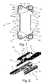
- Fig. 1 is a schematic view of a plate heat exchanger gasket 10 in accordance with an embodiment of the invention.
- the sectional plate heat exchanger gasket 10 comprises a first end section 11, a second end section 12 and two side sections 13 and 14, respectively.
- the end and side sections 11, 12, 13 and 14 are separate parts, each comprising connection end portions 20, 30 which can be connected to mating connection end portions 20, 30 of another section 11, 12, 13 and 14 of the gasket 10. Examples for details of different connection end portions to be used are shown for instance in Fig. 2 and Figs. 5a to 7e , respectively, and will be described in connection therewith.
- Fig. 1 the heat exchanger plate is not shown but the relative position of the entrance orifice 3 for the primary fluid, the exit orifice 4 for the primary fluid, the entrance orifice 5 for the secondary fluid and the exit orifice 6 for the secondary fluid are indicated by respective circles.
- the plate heat exchanger gasket 10 is intended to be fitted into a plate heat exchanger comprising a plurality of heat exchanger plates.
- the heat exchanger plates are arranged in spaced face to face relationship to define flow spaces between them and having manifolds for supply and discharge of fluid media to and from the flow spaces through respective entrance and exit orifices in the heat exchanger plates.
- the heat exchanger plates are sealed at their outer edges and around the orifices 3, 4, 5, 6 by the plate heat exchanger gaskets 10 which are designed and arranged such that the two fluids (for instance a liquid and a heating and/or cooling medium) are directed alternately into the spaces as defined by two adjacent heat exchanger plates and the plate heat exchanger gasket 10 being clamped between the plates.
- the first end section 11 comprises an open orifice portion 111 surrounding respective exit orifices 6 for the secondary fluid provided in the heat exchanger plates.
- the open orifice portion is adapted and designed such that the open orifices 6 of the two adjacent heat exchanger plates 1 (not shown in Fig. 1 ) are sealed against the outside wherein the passage to the space defined between the two adjacent heat exchanger plates is left open.
- the first end section 11 comprises in addition a sealed orifice portion 112 for sealing respective sealed entrance orifices 3 for the primary fluid provided in the heat exchanger plates against the outside (environment).
- the sealed orifice portion comprises an orifice sealing portion 113 surrounding the sealed entrance orifices 3 as first sealing element for sealing the sealed entrance orifices 3 against the space defined between the two adjacent heat exchanger plates.
- the pockets are further defined by secondary pocket forming members 116 and 117 extending between the orifice sealing portion 113 and the second sealing member 114.
- the pockets 115 are vented to the environment such that in the rare event of a failure of one of the gasket portions there is an escape path for the pressurised fluid entering the pocket.
- the fluid exiting the pocket will provide a visual indication of the leakage.
- the provision of the second sealing member and the vented pockets will make the intermixing of the two fluids practically impossible.
- the second end section 12 corresponds essentially to the first end section 11. Similar parts are designated with similar reference numbers starting with 12 instead of 11. Reference is made to the description of the first end section 11.
- the second end section 12 comprises an open orifice portion 121 surrounding respective entrance orifices 5 for the secondary fluid provided in the heat exchanger plates and a sealed orifice portion 122.
- the orifice sealing portion 123 surrounds the respective exit orifices 4 for the primary fluid provided in the heat exchanger plates.
- the gasket may be provided as shown in Fig. 1 with fixing elements 40.
- fixing elements are for instance described in EP 1196730 B1 , the full contents thereof is included by reference.
- the fixing elements provide a mechanical method of attachment of the gasket to the groove of one of the heat exchanger plates. Therefore no adhesive is required to retain the gasket in its position in the groove of the heat exchanger plate. During re-gasketting this offers users substantial savings in time and money for no increase in initial costs.
- Essential advantages arise in combination with the sectional gasket in accordance with the invention because the fixing elements are further means for securing the correct connection between the various sections of the sectional gasket.
- FIG. 3 is a schematic view of a heat exchanger plate 1 having three modules 51, 52 and 53 with patterns imprinted.
- a plate heat exchanger gasket 10 in accordance with an embodiment of the invention is provided comprising first and second end sections and three side sections 13 and 14 at both sides.
- the end sections and side sections are provided with connection end portions 20, 30 embodied for instance as shown in Fig. 2 and Figs. 5a to 7e , respectively.
- the length of the side sections 13, 14 corresponds to the extension of the modules 51, 52, 53.
- Fig. 2 is a schematic view of the connection of two sections 11, 12, 13 and/or 14 of a plate heat exchanger gasket 10 in accordance with an embodiment of the invention.
- the first section (end section or side section) comprises at its end a male connection end portion 20.
- the second section to be connected thereto comprises a mating female connection end portion 30.
- the male connection end portion 20 is shown rotated by about 90 degrees anticlockwise about the gasket section longitudinal axis relative to the female connection end portion 30.
- the male connection end portion 20 comprises a first connection member 21 having a U-shaped recess.
- the female connection end portion 30 comprises at its very end a mating first connection member 31 having a corresponding U-shaped protrusion snugly fitting into the corresponding U-shaped recess.
- the male connection end portion 20 comprises a third connection member 23 having a U-shaped protrusion.
- the female connection end portion 30 comprises at its opposite end a mating third connection member 33 having a corresponding U-shaped recess closely housing the corresponding U-shaped protrusion of the third connection member 23 of the male connection end portion.
- the male connection end portion 20 comprises in the middle of its surface 24 a protrusion
- the female connection end portion 30 comprises in the middle of its surface 34 a recess or indent.
- the dimensions are such that the protrusion is press-fitted into the recess.
- connection members With the three pairs of connection members a secure connection between two sections is provided.
- the connection can easily be made for instance when new gaskets are to be build into an existing plate heat exchanger.
- the respective section has its full cross section portion 25 and 35, respectively, extending to the other end of the section where preferably as indicated in Fig. 1 another male or female connection end portion 20, 30 is provided.
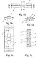
- Figs. 5a to 5e show an alternative embodiment of the connection between two sections.
- the same reference numbers are used to designate the same or similar parts as in the description of the other embodiments.
- Special reference is made to the description of the embodiment as shown in Fig. 2 . In the following only the differences are described.
- the first connection member 21 of the male connection end portion 20 comprises a U-shaped protrusion instead of a U-shaped recess. Consequently the first connection member 31 of the female connection end portion 30 comprises a U-shaped recess instead of a U-shaped protrusion.
- the third connection member 23 of the male connection end portion 20 comprises a U-shaped recess instead of a U-shaped protrusion. Consequently the third connection member 33 of the female connection end portion 30 comprises a U-shaped protrusion instead of a U-shaped recess.
- connection portion The resulting surfaces 24 and 34, respectively, of the connection portion are essentially cross-shaped wherein the respective second connection member 22 and 32, respectively, is provided essentially in the middle of the surface 24, and 34, respectively.
- the protrusions of the first connection member 21, the second connection member 22 and the third connection member 33 are provided with beads and the corresponding recesses of the connection members 31, 32 and 23, respectively are provided with corresponding recesses in its sidewalls.
- This embodiment provides further stability and a better handling for the instalment of the gaskets into the grooves of the heat exchanger plates.
- first and third connection member of the male or female connection portion both can have a protrusion whereas the corresponding connection members of the other connection portion both have U-shaped recesses. This will result in Y-shaped surfaces.
- protrusions and recesses can have other forms mating each other.
Landscapes
- Engineering & Computer Science (AREA)
- Physics & Mathematics (AREA)
- Thermal Sciences (AREA)
- Mechanical Engineering (AREA)
- General Engineering & Computer Science (AREA)
- Heat-Exchange Devices With Radiators And Conduit Assemblies (AREA)
Abstract
The present invention relates to plate heat exchanger gasket (10) to be arranged between two adjacent heat exchanger plates of a plate heat exchanger, the plate heat exchanger gasket (10) having at least two side sections (13, 14) for sealing a fluid flow space between two adjacent heat exchanger plates, and a first and a second end section (11, 12) each comprising a respective open orifice portion (111, 121) for sealing respective open orifices (5, 6) of the heat exchanger plates against the outside and for leaving an opening to the space defined between the two adjacent heat exchanger plates, and a respective sealed orifice portion (112, 122) for sealing respective sealed orifices (3, 4) of the heat exchanger plates against the outside and against the space defined between the two adjacent heat exchanger plates, wherein the first end section (11) and the second end section (12) are separate parts of the gasket (10).
Description
- The present invention relates to a plate heat exchanger gasket in accordance with the preamble of
claim 1. - Plate heat exchangers comprise a plurality of heat exchanger plates wherein a primary fluid is flowing along one side of one heat exchanger plate and a second fluid is flowing along the opposite side of this heat exchanger plate such that a heat transfer from the hotter fluid to the cooler fluid takes place through the heat exchanger plate. It is desired that the fluids do not contact each other. Therefore gaskets are provided between adjacent heat exchanger plates and the heat exchanger plates are provided with separate entrance and exit openings for the different fluids. The gaskets surround the entrance and exit openings for one fluid but do not surround the entrance and exit openings for the other fluid. In addition the gaskets define the spaces between two adjacent heat exchanger plates where the fluid is supposed to flow.
- There is a need to provide plate heat exchangers of different sizes such that the size is adapted to the demand of the device where the plate heat exchanger is intended to be used. One option to change the size is to increase the number of heat exchanger plates to obtain a larger plate heat exchanger. However there are practical limitations in the number of heat exchanger plates due to the available space and/or the performance of the plate heat exchanger. Another option to change the size of the plate heat exchanger is to increase the size of the heat exchanger plates and the corresponding plate heat exchanger gaskets in one or both directions of the heat exchanger plate plane.
- For plate heat exchangers unitary gaskets are used. The skilled person in the field of plate heat exchangers would never have considered using sectional gaskets, i.e. gaskets made in sections to be connected with each other without being permanently fused together to obtain a single piece gasket, as plate heat exchanger gaskets.
-
US patent No. 2,768,036 discloses a sectional fluid seal to be used to provide a fluid tight joint between two longitudinally movable members of pneumatic motors. The friction causes the seal to twist. In order to avoid a damage of the seal the individual segments of the seal are capable of independent rotation around their own longitudinal centre line. At the ends of the segments there are ball and corresponding sockets provided. The skilled person would never consider using such sectional fluid seals for plate heat exchanger because the gaskets used in plate heat exchangers are provided between two stationary heat exchanger plates. Therefore twisting forces would never be applied onto the plate heat exchanger gaskets and it would not be necessary to split the gasket for that reason, i.e. in order to enable individual segments of the gasket to independently rotate around their own longitudinal centre line. - From
US patent No. 4.572.522 and the prior art cited therein it is known to provide gaskets made in sections in order to obtain gaskets of large size. The gaskets as disclosed in theUS patent No. 4.572.522 are made out of gasket sections having a button at the very end of each end of the section to fit into a corresponding opening of the adjacent section to be connected therewith. There is the disadvantage that the button at the very end can be damaged due to its position at the very end of the section resulting in undesired leakage and/or problems with assembling the gasket. In order to enhance the stability of the buttons, rigid cores extending into the buttons are provided. The skilled person would never consider using such gaskets for plate heat exchangers without fusing the sections together permanently in order to obtain a single-piece gasket. -
US Patent No. 1,968,465 discloses a gasket to be used in oil transformers for sealing between an oil reservoir portion and the oil reservoir cover. Clearly it would be desirable to provide a single piece gasket to provide the best possible sealing effect. However for some large oil transformers gaskets over 50 feet in length are needed and it is not practicable to either manufacture or handle such a large gasket.US Patent No. 1,968,465 suggests a gasket having spaced contour changing pieces and filler strips connecting the ends of the spaced contour changing pieces. The skilled person would never consider using such gaskets for plate heat exchangers without fusing the pieces together permanently to obtain a single-piece gasket. - To manufacture plate heat exchanger gaskets and heat exchanger plates of different sizes it is known to provide a different tool for each size. These tools are used to mould the desired gasket and to press the desired pattern into the heat exchanger plate, respectively. Since the costs for each tool needed are very high it is desired to reduce the number of tools. Accordingly the skilled person would prefer to change the number of plates instead of changing the size of the individual plate heat exchanger gaskets and heat exchanger plates in order to achieve the desired capacity of the plate heat exchanger.
- Therefore, it is an object of the invention to provide plate heat exchanger gaskets and corresponding heat exchanger plates which can be produced in different sizes with low manufacturing costs and whereby the gaskets can easily be assembled onto the heat exchanger plates and into the plate heat exchanger, respectively, without a need to fuse parts and/or sections of the gasket together permanently.
- The object of the invention is achieved by a plate heat exchanger gasket with the features of
claim 1 and/or claim 2. - Preferred embodiments are disclosed in the dependent claims.
- According to one aspect of the invention there is provided a plate heat exchanger gasket to be arranged between two adjacent heat exchanger plates of a plate heat exchanger, the plate heat exchanger gasket having at least two side sections for sealing a fluid flow space between two adjacent heat exchanger plates, and a first and a second end section each comprising a respective open orifice portion for sealing respective open orifices of the heat exchanger plates against the outside and for leaving an opening to the space defined between the two adjacent heat exchanger plates, and a respective sealed orifice portion for sealing respective sealed orifices of the heat exchanger plates against the outside and against the space defined between the two adjacent heat exchanger plates, wherein the first end section and the second end section are separate parts of the gasket and/or wherein the first end section, the second end section and the side sections comprise at least one pair of mating connection end portions, wherein the pair of mating connection end portions preferably comprises a male connection end portion and a mating female connection end portion.
- According to the invention the side and end sections can each comprise at their respective ends to be connected with another end of an end or side section of the plate heat exchanger gasket connection respective end portions for connecting the end of the side or end section to a corresponding end of another end or side section of the plate heat exchanger gasket.
- According to the invention the plate heat exchanger gasket can further comprise a plurality of side sections at each of its sides, wherein the number of side sections at each sides of the plate heat exchanger gasket and the length of each side section is preferably the same. Preferably the side sections of the plurality of side sections at one side of the plate heat exchanger gasket are interconnected by means of mating connection end portions.
- According to the invention the end sections can be made of at least two subsections having connection end portions. Preferably the plate heat exchanger gasket can further comprise at least one extension section provided between the subsections of one end section and having connection end portions. In addition each end section can comprise a plurality of extension sections, wherein the number of extension sections at each end section of the plate heat exchanger gasket and the length of each extension section is preferably the same. Thereby the extension sections of one end section of the plate heat exchanger gasket can be interconnected by means of mating connection end portions.
- According to the invention the end sections each can comprise an orifice sealing portion. In addition the end sections each can comprise a second sealing portion.
- According to the invention the male connection end portion can comprise at least two connection members, wherein the first connection member is located closer to the very end of the male connection end portion than the second connection member, and wherein the second connection member is a protrusion extending essentially perpendicular to the plane of the gasket from the gasket.
- In this specification "plane of the gasket" is meant to refer to a plane lying substantially in parallel to the plane of a heat exchanger plate the gasket is in use with, and/or to a plane lying substantially in parallel to the planes of the two heat exchanger plates the gasket is fitted between in use.
- According to the invention the male connection end portion can comprise three connection members including a first, second and third connection member, wherein the second connection member is located along the longitudinal direction of the gasket between the first and third connection member of the male connection end portion, and wherein the second connection member is a protrusion extending essentially perpendicular to the plane of the gasket from the gasket.
- According to the invention the female connection end portion can be adapted and arranged to be mating with the male connection portion, wherein the female connection end portion preferably comprises at least two connection members, wherein the first connection member is located closer to the very end of the female connection end portion than the second connection member, and wherein the second connection member is a recess extending essentially perpendicular to the plane of the gasket into the gasket.
- According to the invention the female connection end portion can comprise three connection members including a first, second and third connection member, wherein the second connection member is located along the longitudinal direction of the gasket between the first and third connection member of the female connection end portion, and wherein the second connection member is a recess extending essentially perpendicular to the plane of the gasket into the gasket.
- According to the invention the first connection member and/or the second connection member of the male and/or the female connection end portion can comprise a respective protrusion or recess, which is preferably U-shaped.
- According to the invention the male and/or female connection end portions can comprise respective surfaces, wherein the surfaces are preferably H-shaped, cross shaped and/or Y-shaped.
- According to the invention the second connection members of the male and female connection end portions can be essentially located in the centre of the respective surface of its male and female connection end portion, respectively. This has the advantage that the protrusions of the second connection members can be located at a distance from the very end of the connection end portion, thus providing a greater strength and limiting potential damages thereto. Accordingly it will generally not be necessary to provide reinforcements such as incorporating fibres into the material of the gasket in the area of the second connection member. However it is clear that reinforcements such as fibres or any other means known to the skilled person may still be provided.
- According to the invention preferably all protrusions of the first, second and/or third connection members of the male and female connection end portions can be provided with beads. In addition the corresponding recesses can be provided with respective recesses for housing the beads. The dimensions are preferably chosen such that a press-fit is obtained.
- According to the invention mating male and female connection end portions can also be glued, cured, welded, brazed and/or vulcanized with each other. This will generally not be necessary because the connection provides a sufficient mechanical fixation. However it is not intended to exclude an additional fixation such as those mentioned here.
- According to the invention the plate heat exchanger gasket can preferably be made of rubber. In addition, any material used for plate heat exchanger gaskets can be used.
- According to the invention fixing elements can be provided at the end and/or side sections of the plate heat exchanger gasket for mechanically fixing the sections onto a heat exchanger plate to which the gasket is to be fixed.
- According to the invention there is also provided a side section and/or an end section for a plate heat exchanger gasket with any of the above mentioned features having a male connection end portion and/or a female connection end portion in accordance with the above mentioned features related thereto.
- The invention also relates to a plate heat exchanger having a plurality of plate heat exchanger gaskets in accordance with the invention. In addition the plate heat exchanger can further comprise heat exchanger plates having at least one module with a pattern, wherein the length of a side section corresponds to an extension of the module of the heat exchanger plate, wherein the heat exchanger plates preferably comprise a plurality of modules having the same extension, and wherein the plate heat exchanger gasket has the same number of side sections having the same length as the extension of the modules, wherein the length of the side sections is preferably the same.
- Preferred embodiments of the invention are shown in the attached drawings.
- Fig. 1
- is a schematic view of a plate heat exchanger gasket in accordance with an embodiment of the invention.
- Fig. 2
- is a schematic view of the connection of two sections of a plate heat exchanger gasket in accordance with an embodiment of the invention.
- Fig. 3
- is a schematic view of a heat exchanger plate having three modules in accordance with an embodiment of the invention including a plate heat exchanger gasket in accordance with an embodiment of the invention.
- Fig. 4
- is a schematic view of a heat exchanger plate having two modules in accordance with an embodiment of the invention including a plate heat exchanger gasket in accordance with an embodiment of the invention.
- Fig. 5a
- is a schematic side view of the connection of two sections of a plate heat exchanger gasket in accordance with another embodiment of the invention.
- Fig. 5b
- is a schematic front view of the plate heat exchanger gasket of
Fig 5a . - Fig. 5c
- is a schematic top view of the plate heat exchanger gasket of
Fig 5a . - Fig. 5d
- is a schematic sectional view along lines Vd-Vd of
Fig. 5c . - Fig. 5e
- is a schematic sectional view along lines Ve-Ve of
Fig. 5a . - Fig. 6a
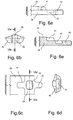
- is a schematic side view of the female connection portion of the plate heat exchanger gasket of
Fig. 5a . - Fig. 6b
- is a schematic front view of the female connection portion of
Fig 6a . - Fig. 6c
- is a schematic top view of the female connection portion of
Fig 6a . - Fig. 6d
- is a schematic sectional view along lines VId-VId of
Fig. 6c . - Fig. 6e
- is a schematic sectional view along lines VIe-VIe of
Fig. 6b . - Fig. 7a
- is a schematic side view of the male connection portion of the plate heat exchanger gasket of
Fig. 5a . - Fig. 7b
- is a schematic front view of the female connection portion of
Fig 7a . - Fig. 7c
- is a schematic top view of the female connection portion of
Fig 7a . - Fig. 7d
- is a schematic sectional view along lines VIId-VIId of
Fig. 7c . - Fig. 7e
- is a schematic sectional view along lines VIIe-VIIe of
Fig. 7b . - The invention will be explained in further detail with reference to the drawings, wherein the following reference numbers are used:
- 1
- heat exchanger plate
- 3
- entrance orifice for the primary fluid
- 4
- exit orifice for the primary fluid
- 5
- entrance orifice for the secondary fluid
- 6
- exit orifice for the secondary fluid
- 10
- plate heat exchanger gasket
- 11
- first end section
- 111
- open orifice portion
- 112
- sealed orifice portion
- 113
- orifice sealing portion
- 114
- second sealing portion
- 115
- 116
- secondary pocket forming member
- 117
- secondary pocket forming member
- 12
- second end section
- 121
- open orifice portion
- 122
- sealed orifice portion
- 123
- orifice sealing portion
- 124
- second sealing portion
- 125
- 126
- secondary pocket forming member
- 127
- secondary pocket forming member
- 13
- side section
- 14
- side section
- 20
- male connection end portion
- 21
- first connection member (U-shaped recess or protrusion)
- 22
- second connection member (protrusion)
- 23
- third connection member (U-shaped protrusion or recess)
- 24
- surface (H-shaped or cross-shaped)
- 25
- full cross section portion
- 30
- female connection end portion
- 31
- first connection member (U-shaped protrusion or recess)
- 32
- second connection member (recess)
- 33
- third connection member (U-shaped recess or protrusion)
- 34
- surface (H-shaped or cross-shaped)
- 35
- full cross section portion
- 40
- fixing element
- 51
- first module
- 52
- second module
- 53
- third module
-
Fig. 1 is a schematic view of a plateheat exchanger gasket 10 in accordance with an embodiment of the invention. The sectional plateheat exchanger gasket 10 comprises afirst end section 11, asecond end section 12 and twoside sections side sections connection end portions connection end portions section gasket 10. Examples for details of different connection end portions to be used are shown for instance inFig. 2 andFigs. 5a to 7e , respectively, and will be described in connection therewith. - For illustrative purposes the side sections are shown relatively displaced with respect to their position when fitted together with the end sections as illustrated for instance in
Fig. 3 . - In
Fig. 1 the heat exchanger plate is not shown but the relative position of theentrance orifice 3 for the primary fluid, theexit orifice 4 for the primary fluid, theentrance orifice 5 for the secondary fluid and theexit orifice 6 for the secondary fluid are indicated by respective circles. - The plate
heat exchanger gasket 10 is intended to be fitted into a plate heat exchanger comprising a plurality of heat exchanger plates. The heat exchanger plates are arranged in spaced face to face relationship to define flow spaces between them and having manifolds for supply and discharge of fluid media to and from the flow spaces through respective entrance and exit orifices in the heat exchanger plates. The heat exchanger plates are sealed at their outer edges and around theorifices heat exchanger gaskets 10 which are designed and arranged such that the two fluids (for instance a liquid and a heating and/or cooling medium) are directed alternately into the spaces as defined by two adjacent heat exchanger plates and the plateheat exchanger gasket 10 being clamped between the plates. - The
first end section 11 comprises anopen orifice portion 111 surroundingrespective exit orifices 6 for the secondary fluid provided in the heat exchanger plates. The open orifice portion is adapted and designed such that theopen orifices 6 of the two adjacent heat exchanger plates 1 (not shown inFig. 1 ) are sealed against the outside wherein the passage to the space defined between the two adjacent heat exchanger plates is left open. - The
first end section 11 comprises in addition a sealedorifice portion 112 for sealing respective sealedentrance orifices 3 for the primary fluid provided in the heat exchanger plates against the outside (environment). The sealed orifice portion comprises anorifice sealing portion 113 surrounding the sealedentrance orifices 3 as first sealing element for sealing the sealedentrance orifices 3 against the space defined between the two adjacent heat exchanger plates. As a second sealing element there is asecond sealing portion 114 located between theorifice sealing portion 113 and the space defined between the two adjacent heat exchanger plates. There arepockets 115 formed betweenorifice sealing portion 113 and thesecond sealing portion 114. The pockets are further defined by secondarypocket forming members orifice sealing portion 113 and thesecond sealing member 114. Preferably thepockets 115 are vented to the environment such that in the rare event of a failure of one of the gasket portions there is an escape path for the pressurised fluid entering the pocket. The fluid exiting the pocket will provide a visual indication of the leakage. The provision of the second sealing member and the vented pockets will make the intermixing of the two fluids practically impossible. - The
second end section 12 corresponds essentially to thefirst end section 11. Similar parts are designated with similar reference numbers starting with 12 instead of 11. Reference is made to the description of thefirst end section 11. Thesecond end section 12 comprises anopen orifice portion 121 surroundingrespective entrance orifices 5 for the secondary fluid provided in the heat exchanger plates and a sealedorifice portion 122. Theorifice sealing portion 123 surrounds therespective exit orifices 4 for the primary fluid provided in the heat exchanger plates. - The gasket may be provided as shown in
Fig. 1 with fixingelements 40. Such fixing elements are for instance described inEP 1196730 B1 , the full contents thereof is included by reference. The fixing elements provide a mechanical method of attachment of the gasket to the groove of one of the heat exchanger plates. Therefore no adhesive is required to retain the gasket in its position in the groove of the heat exchanger plate. During re-gasketting this offers users substantial savings in time and money for no increase in initial costs. Essential advantages arise in combination with the sectional gasket in accordance with the invention because the fixing elements are further means for securing the correct connection between the various sections of the sectional gasket. - The advantages of the sectional plate heat exchanger gasket will become clear from the following description of the
heat exchanger plates 1 withgaskets 10 as shown inFigs. 3 and 4. Fig. 3 is a schematic view of aheat exchanger plate 1 having threemodules heat exchanger gasket 10 in accordance with an embodiment of the invention is provided comprising first and second end sections and threeside sections connection end portions Fig. 2 andFigs. 5a to 7e , respectively. The length of theside sections modules heat exchanger plate 1 with only twomodules heat exchanger gasket 10 as shown inFig. 4 , he can use the same tools as for manufacturing the larger heat exchanger plate. For the heat exchanger gasket a side section at each side has to be omitted and a shorter heat exchanger plate can be patterned with the same tool providing the pattern of a single module. In the same way larger heat exchanger modules with 4, 5, 6 or more modules can be manufactured at low manufacturing costs. -
Fig. 2 is a schematic view of the connection of twosections heat exchanger gasket 10 in accordance with an embodiment of the invention. The first section (end section or side section) comprises at its end a maleconnection end portion 20. The second section to be connected thereto comprises a mating femaleconnection end portion 30. For illustrative purposes the maleconnection end portion 20 is shown rotated by about 90 degrees anticlockwise about the gasket section longitudinal axis relative to the femaleconnection end portion 30. - At its very end the male
connection end portion 20 comprises afirst connection member 21 having a U-shaped recess. The femaleconnection end portion 30 comprises at its very end a matingfirst connection member 31 having a corresponding U-shaped protrusion snugly fitting into the corresponding U-shaped recess. At its opposite end the maleconnection end portion 20 comprises athird connection member 23 having a U-shaped protrusion. The femaleconnection end portion 30 comprises at its opposite end a matingthird connection member 33 having a corresponding U-shaped recess closely housing the corresponding U-shaped protrusion of thethird connection member 23 of the male connection end portion. These elements are providing a positive locking of the two sections with regard to a sideward directed force. There aresurfaces connection end portions Fig. 2 thesurfaces
Essentially at the centre of the surface there is a respectivesecond connection member connection end portion 20 comprises in the middle of its surface 24 a protrusion, whereas the femaleconnection end portion 30 comprises in the middle of its surface 34 a recess or indent. Preferably the dimensions are such that the protrusion is press-fitted into the recess. These elements are providing a positive locking of the two sections with regard to a force directed into the longitudinal direction of the gasket. - With the three pairs of connection members a secure connection between two sections is provided. The connection can easily be made for instance when new gaskets are to be build into an existing plate heat exchanger.
- After the
third connection member cross section portion Fig. 1 another male or femaleconnection end portion -
Figs. 5a to 5e show an alternative embodiment of the connection between two sections. The same reference numbers are used to designate the same or similar parts as in the description of the other embodiments. Special reference is made to the description of the embodiment as shown inFig. 2 . In the following only the differences are described. - The
first connection member 21 of the maleconnection end portion 20 comprises a U-shaped protrusion instead of a U-shaped recess. Consequently thefirst connection member 31 of the femaleconnection end portion 30 comprises a U-shaped recess instead of a U-shaped protrusion. Thethird connection member 23 of the maleconnection end portion 20 comprises a U-shaped recess instead of a U-shaped protrusion. Consequently thethird connection member 33 of the femaleconnection end portion 30 comprises a U-shaped protrusion instead of a U-shaped recess. - The resulting surfaces 24 and 34, respectively, of the connection portion are essentially cross-shaped wherein the respective
second connection member surface - The protrusions of the
first connection member 21, thesecond connection member 22 and thethird connection member 33 are provided with beads and the corresponding recesses of theconnection members - The skilled person will recognize that other embodiments are possible. For instance the first and third connection member of the male or female connection portion both can have a protrusion whereas the corresponding connection members of the other connection portion both have U-shaped recesses. This will result in Y-shaped surfaces.
- The skilled person will also recognize that the protrusions and recesses can have other forms mating each other.
- It is clear that the description of the specific embodiments of the invention is not to be intended to limit the scope of protection which is defined by the claims. It is also clear that obvious alternatives which the skilled person will notice by reading the specification are intended to be in the scope of protection as defined by the claims.
Claims (26)
- Plate heat exchanger gasket to be arranged between two adjacent heat exchanger plates of a plate heat exchanger, the plate heat exchanger gasket having- at least two side sections for sealing a fluid flow space between two adjacent heat exchanger plates, and- a first and a second end section each comprising- a respective open orifice portion for sealing respective open orifices of the heat exchanger plates against the outside and for leaving an opening to the space defined between the two adjacent heat exchanger plates, and- a respective sealed orifice portion for sealing respective sealed orifices of the heat exchanger plates against the outside and against the space defined between the two adjacent heat exchanger plates,characterised in that the first end section and the second end section are separate parts of the gasket.
- Plate heat exchanger gasket of claim 1 or the preamble of claim 1, wherein the first end section, the second end section and the side section comprise at least one pair of mating connection end portions, wherein the pair of mating connection end portions preferably comprises a male connection end portion and a mating female connection end portion.
- Plate heat exchanger gasket of any of the preceding claims, wherein the side and end sections each comprise at their respective ends to be connected with another end of an end or side section of the plate heat exchanger gasket connection respective end portions for connecting the end of the side or end section to a corresponding end of another end or side section of the plate heat exchanger gasket.
- Plate heat exchanger gasket of any of the preceding claims, further comprising a plurality of side sections at each of its sides, wherein the number of side sections at each sides of the plate heat exchanger gasket and the length of each side section is preferably the same.
- Plate heat exchanger gasket of the preceding claim, wherein the side sections of the plurality of side sections at one side of the plate heat exchanger gasket are interconnected by means of mating connection end portions.
- Plate heat exchanger gasket of any of the preceding claims, wherein the end sections are made of at least two subsections having connection end portions.
- Plate heat exchanger gasket of the preceding claim, further comprising at least one extension section provided between the subsections of one end section and having connection end portions.
- Plate heat exchanger gasket of the preceding claim, wherein each end section comprises a plurality of extension sections, wherein the number of extension sections at each end section of the plate heat exchanger gasket and the length of each extension section is preferably the same.
- Plate heat exchanger gasket of the preceding claim, wherein the extension sections of one end section of the plate heat exchanger gasket are interconnected by means of mating connection end portions.
- Plate heat exchanger gasket of any of the preceding claims, wherein the end sections each comprise an orifice sealing portion.
- Plate heat exchanger gasket of the preceding claim, wherein the end sections each comprise a second sealing portion.
- Plate heat exchanger gasket of any of the preceding claims, wherein the male connection end portion comprises at least two connection members, wherein the first connection member is located closer to the very end of the male connection end portion than the second connection member, and wherein the second connection member is a protrusion extending essentially perpendicular to the plane of the gasket from the gasket.
- Plate heat exchanger gasket of any of the preceding claims, wherein the male connection end portion comprises three connection members including a first, second and third connection member, wherein the second connection member is located along the longitudinal direction of the gasket between the first and third connection member of the male connection end portion, and wherein the second connection member is a protrusion extending essentially perpendicular to the plane of the gasket from the gasket.
- Plate heat exchanger gasket of any of the preceding claims, wherein the female connection end portion is adapted and arranged to be mating with the male connection portion, wherein the female connection end portion preferably comprises at least two connection members, wherein the first connection member is located closer to the very end of the female connection end portion than the second connection member, and wherein the second connection member is a recess extending essentially perpendicular to the plane of the gasket into the gasket.
- Plate heat exchanger gasket of any of the preceding claims, wherein the female connection end portion comprises three connection members including a first, second and third connection member, wherein the second connection member is located along the longitudinal direction of the gasket between the first and third connection member of the female connection end portion, and wherein the second connection member is a recess extending essentially perpendicular to the plane of the gasket into the gasket.
- Plate heat exchanger gasket of any of the preceding claims, wherein the first connection member and/or the second connection member of the male and/or the female connection end portion comprise a respective protrusion or recess, which is preferably U-shaped.
- Plate heat exchanger gasket of any of the preceding claims, wherein the male and/or female connection end portions comprise respective surfaces, wherein the surfaces are preferably H-shaped, cross shaped and/or Y-shaped.
- Plate heat exchanger gasket of the preceding claim, wherein the second connection members of the male and female connection end portions are essentially located in the centre of the respective surface of its male and female connection end portion, respectively.
- Plate heat exchanger gasket of any of the preceding claims, wherein preferably all protrusions of the first, second and/or third connection members of the male and female connection end portions are provided with beads.
- Plate heat exchanger gasket of any of the preceding claims, wherein mating male and female connection end portions are glued, cured, welded, brazed and/or vulcanized with each other.
- Plate heat exchanger gasket of any of the preceding claims, wherein the gasket is made of rubber.
- Plate heat exchanger gasket of any of the preceding claims, wherein fixing elements are provided at the end and/or side sections of the plate heat exchanger gasket for mechanically fixing the sections onto a heat exchanger plate to which the gasket is to be fixed.
- Side section for a plate heat exchanger gasket of any of the preceding claims having a male connection end portion and/or a female connection end portion in accordance with features of any of claims 12 to 19.
- End section for a plate heat exchanger gasket of any of the preceding claims having a male connection end portion and/or a female connection end portion in accordance with features of any of claims 12 to 19.
- Plate heat exchanger having a plurality of plate heat exchanger gaskets in accordance with any of the preceding claims.
- Plate heat exchanger of the preceding claim, further comprising heat exchanger plates having at least one module with a pattern, wherein the length of a side section corresponds to an extension of the module of the heat exchanger plate, wherein the heat exchanger plates preferably comprise a plurality of modules having the same extension, and wherein the plate heat exchanger gasket has the same number of side sections having the same length as the extension of the modules, wherein the length of the side sections is preferably the same.
Priority Applications (5)
| Application Number | Priority Date | Filing Date | Title |
|---|---|---|---|
| EP07014018A EP2017562A1 (en) | 2007-07-17 | 2007-07-17 | Plate heat exchanger gasket |
| CN200880024767A CN101755185A (en) | 2007-07-17 | 2008-07-16 | Plate heat exchanger gasket |
| PCT/EP2008/005816 WO2009010285A1 (en) | 2007-07-17 | 2008-07-16 | Plate heat exchanger gasket |
| JP2010516419A JP2010533834A (en) | 2007-07-17 | 2008-07-16 | Plate heat exchanger gasket |
| EP08774002A EP2179242A1 (en) | 2007-07-17 | 2008-07-16 | Plate heat exchanger gasket |
Applications Claiming Priority (1)
| Application Number | Priority Date | Filing Date | Title |
|---|---|---|---|
| EP07014018A EP2017562A1 (en) | 2007-07-17 | 2007-07-17 | Plate heat exchanger gasket |
Publications (1)
| Publication Number | Publication Date |
|---|---|
| EP2017562A1 true EP2017562A1 (en) | 2009-01-21 |
Family
ID=38814309
Family Applications (2)
| Application Number | Title | Priority Date | Filing Date |
|---|---|---|---|
| EP07014018A Withdrawn EP2017562A1 (en) | 2007-07-17 | 2007-07-17 | Plate heat exchanger gasket |
| EP08774002A Withdrawn EP2179242A1 (en) | 2007-07-17 | 2008-07-16 | Plate heat exchanger gasket |
Family Applications After (1)
| Application Number | Title | Priority Date | Filing Date |
|---|---|---|---|
| EP08774002A Withdrawn EP2179242A1 (en) | 2007-07-17 | 2008-07-16 | Plate heat exchanger gasket |
Country Status (4)
| Country | Link |
|---|---|
| EP (2) | EP2017562A1 (en) |
| JP (1) | JP2010533834A (en) |
| CN (1) | CN101755185A (en) |
| WO (1) | WO2009010285A1 (en) |
Cited By (2)
| Publication number | Priority date | Publication date | Assignee | Title |
|---|---|---|---|---|
| EP3859260B1 (en) | 2020-01-29 | 2023-06-21 | Alfa Laval Vicarb SAS | A plate heat exchanger |
| EP4660565A1 (en) | 2024-06-05 | 2025-12-10 | Kelvion PHE GmbH | Plate heat exchanger |
Families Citing this family (2)
| Publication number | Priority date | Publication date | Assignee | Title |
|---|---|---|---|---|
| PL3489606T3 (en) * | 2017-11-22 | 2025-12-15 | Danfoss A/S | HEAT EXCHANGE PLATE FOR PLATE HEAT EXCHANGER AND PLATE HEAT EXCHANGER WITH SUCH PLATE |
| KR102143827B1 (en) * | 2020-01-22 | 2020-08-12 | 케이티씨 주식회사 | Gasket Structure of Plate Heat Exchanger |
Citations (2)
| Publication number | Priority date | Publication date | Assignee | Title |
|---|---|---|---|---|
| GB2092241A (en) * | 1981-01-30 | 1982-08-11 | Apv The Co Ltd | Gasket arrangement for plate heat exchanger |
| GB2219387A (en) * | 1988-05-30 | 1989-12-06 | Nagema Veb K | Seal for heat exchanger plates |
-
2007
- 2007-07-17 EP EP07014018A patent/EP2017562A1/en not_active Withdrawn
-
2008
- 2008-07-16 WO PCT/EP2008/005816 patent/WO2009010285A1/en not_active Ceased
- 2008-07-16 EP EP08774002A patent/EP2179242A1/en not_active Withdrawn
- 2008-07-16 JP JP2010516419A patent/JP2010533834A/en active Pending
- 2008-07-16 CN CN200880024767A patent/CN101755185A/en active Pending
Patent Citations (2)
| Publication number | Priority date | Publication date | Assignee | Title |
|---|---|---|---|---|
| GB2092241A (en) * | 1981-01-30 | 1982-08-11 | Apv The Co Ltd | Gasket arrangement for plate heat exchanger |
| GB2219387A (en) * | 1988-05-30 | 1989-12-06 | Nagema Veb K | Seal for heat exchanger plates |
Cited By (4)
| Publication number | Priority date | Publication date | Assignee | Title |
|---|---|---|---|---|
| EP3859260B1 (en) | 2020-01-29 | 2023-06-21 | Alfa Laval Vicarb SAS | A plate heat exchanger |
| US12339071B2 (en) | 2020-01-29 | 2025-06-24 | Alfa Laval Vicarb Sas | Plate heat exchanger |
| EP4660565A1 (en) | 2024-06-05 | 2025-12-10 | Kelvion PHE GmbH | Plate heat exchanger |
| DE102024115589B4 (en) | 2024-06-05 | 2026-06-18 | Kelvion Phe Ii Gmbh | Plate heat exchangers |
Also Published As
| Publication number | Publication date |
|---|---|
| JP2010533834A (en) | 2010-10-28 |
| EP2179242A1 (en) | 2010-04-28 |
| WO2009010285A1 (en) | 2009-01-22 |
| CN101755185A (en) | 2010-06-23 |
Similar Documents
| Publication | Publication Date | Title |
|---|---|---|
| EP0704667B1 (en) | Heat-exchanging conduit tubes for laminated heat exchanger and method for producing same | |
| KR101265442B1 (en) | Plate and gasket for a plate heat exchanger | |
| US9893392B2 (en) | Conformal fluid-cooled heat exchanger for battery | |
| CA2902679C (en) | Plate heat exchanger and method for constructing multiple passes in the plate heat exchanger | |
| EP0719611A1 (en) | Flat tube brazing method for laminated heat exchangers | |
| EP3267138A1 (en) | Heat exchanger | |
| JP5386503B2 (en) | Heat exchanger | |
| EP2179242A1 (en) | Plate heat exchanger gasket | |
| KR100354729B1 (en) | Manufacturing method of flat heat exchanger and press tool used in manufacturing method | |
| JP2005147443A (en) | Laminated type heat exchanger | |
| EP0699292A1 (en) | Heat exchanger | |
| CN210922275U (en) | Heat exchanger | |
| JP7689410B2 (en) | heat exchanger | |
| KR101987599B1 (en) | The plate heat exchanger of welding type | |
| US20250283674A1 (en) | Heat exchanger and its manufacturing method | |
| GB2384299A (en) | Automotive heat exchanger | |
| KR101054681B1 (en) | heat transmitter | |
| JPS63116092A (en) | Cross type heat exchanger | |
| WO2006072774A1 (en) | Modular heat exchanger | |
| KR20170042035A (en) | Many fluid heat exchanger | |
| KR20100097304A (en) | The plate type heat exchanger having safty case | |
| JP2002168582A (en) | Heat exchanger |
Legal Events
| Date | Code | Title | Description |
|---|---|---|---|
| PUAI | Public reference made under article 153(3) epc to a published international application that has entered the european phase |
Free format text: ORIGINAL CODE: 0009012 |
|
| AK | Designated contracting states |
Kind code of ref document: A1 Designated state(s): AT BE BG CH CY CZ DE DK EE ES FI FR GB GR HU IE IS IT LI LT LU LV MC MT NL PL PT RO SE SI SK TR |
|
| AX | Request for extension of the european patent |
Extension state: AL BA HR MK RS |
|
| AKX | Designation fees paid | ||
| STAA | Information on the status of an ep patent application or granted ep patent |
Free format text: STATUS: THE APPLICATION IS DEEMED TO BE WITHDRAWN |
|
| 18D | Application deemed to be withdrawn |
Effective date: 20090722 |
|
| REG | Reference to a national code |
Ref country code: DE Ref legal event code: 8566 |