EP2017503A2 - Synchronized speed shifting of multiple motors - Google Patents
Synchronized speed shifting of multiple motors Download PDFInfo
- Publication number
- EP2017503A2 EP2017503A2 EP07253007A EP07253007A EP2017503A2 EP 2017503 A2 EP2017503 A2 EP 2017503A2 EP 07253007 A EP07253007 A EP 07253007A EP 07253007 A EP07253007 A EP 07253007A EP 2017503 A2 EP2017503 A2 EP 2017503A2
- Authority
- EP
- European Patent Office
- Prior art keywords
- shifting
- speed
- motors
- pressurized fluid
- receptacle
- Prior art date
- Legal status (The legal status is an assumption and is not a legal conclusion. Google has not performed a legal analysis and makes no representation as to the accuracy of the status listed.)
- Withdrawn
Links
Images

Classifications
-
- F—MECHANICAL ENGINEERING; LIGHTING; HEATING; WEAPONS; BLASTING
- F16—ENGINEERING ELEMENTS AND UNITS; GENERAL MEASURES FOR PRODUCING AND MAINTAINING EFFECTIVE FUNCTIONING OF MACHINES OR INSTALLATIONS; THERMAL INSULATION IN GENERAL
- F16H—GEARING
- F16H61/00—Control functions within control units of change-speed- or reversing-gearings for conveying rotary motion ; Control of exclusively fluid gearing, friction gearing, gearings with endless flexible members or other particular types of gearing
- F16H61/38—Control of exclusively fluid gearing
- F16H61/40—Control of exclusively fluid gearing hydrostatic
- F16H61/42—Control of exclusively fluid gearing hydrostatic involving adjustment of a pump or motor with adjustable output or capacity
- F16H61/423—Motor capacity control by fluid pressure control means
-
- F—MECHANICAL ENGINEERING; LIGHTING; HEATING; WEAPONS; BLASTING
- F16—ENGINEERING ELEMENTS AND UNITS; GENERAL MEASURES FOR PRODUCING AND MAINTAINING EFFECTIVE FUNCTIONING OF MACHINES OR INSTALLATIONS; THERMAL INSULATION IN GENERAL
- F16H—GEARING
- F16H61/00—Control functions within control units of change-speed- or reversing-gearings for conveying rotary motion ; Control of exclusively fluid gearing, friction gearing, gearings with endless flexible members or other particular types of gearing
- F16H61/38—Control of exclusively fluid gearing
- F16H61/40—Control of exclusively fluid gearing hydrostatic
- F16H61/44—Control of exclusively fluid gearing hydrostatic with more than one pump or motor in operation
- F16H61/456—Control of the balance of torque or speed between pumps or motors
-
- B—PERFORMING OPERATIONS; TRANSPORTING
- B60—VEHICLES IN GENERAL
- B60Y—INDEXING SCHEME RELATING TO ASPECTS CROSS-CUTTING VEHICLE TECHNOLOGY
- B60Y2200/00—Type of vehicle
- B60Y2200/40—Special vehicles
- B60Y2200/41—Construction vehicles, e.g. graders, excavators
- B60Y2200/415—Wheel loaders
-
- F—MECHANICAL ENGINEERING; LIGHTING; HEATING; WEAPONS; BLASTING
- F15—FLUID-PRESSURE ACTUATORS; HYDRAULICS OR PNEUMATICS IN GENERAL
- F15B—SYSTEMS ACTING BY MEANS OF FLUIDS IN GENERAL; FLUID-PRESSURE ACTUATORS, e.g. SERVOMOTORS; DETAILS OF FLUID-PRESSURE SYSTEMS, NOT OTHERWISE PROVIDED FOR
- F15B2211/00—Circuits for servomotor systems
- F15B2211/30—Directional control
- F15B2211/32—Directional control characterised by the type of actuation
- F15B2211/329—Directional control characterised by the type of actuation actuated by fluid pressure
-
- F—MECHANICAL ENGINEERING; LIGHTING; HEATING; WEAPONS; BLASTING
- F15—FLUID-PRESSURE ACTUATORS; HYDRAULICS OR PNEUMATICS IN GENERAL
- F15B—SYSTEMS ACTING BY MEANS OF FLUIDS IN GENERAL; FLUID-PRESSURE ACTUATORS, e.g. SERVOMOTORS; DETAILS OF FLUID-PRESSURE SYSTEMS, NOT OTHERWISE PROVIDED FOR
- F15B2211/00—Circuits for servomotor systems
- F15B2211/70—Output members, e.g. hydraulic motors or cylinders or control therefor
- F15B2211/705—Output members, e.g. hydraulic motors or cylinders or control therefor characterised by the type of output members or actuators
- F15B2211/7058—Rotary output members
-
- F—MECHANICAL ENGINEERING; LIGHTING; HEATING; WEAPONS; BLASTING
- F15—FLUID-PRESSURE ACTUATORS; HYDRAULICS OR PNEUMATICS IN GENERAL
- F15B—SYSTEMS ACTING BY MEANS OF FLUIDS IN GENERAL; FLUID-PRESSURE ACTUATORS, e.g. SERVOMOTORS; DETAILS OF FLUID-PRESSURE SYSTEMS, NOT OTHERWISE PROVIDED FOR
- F15B2211/00—Circuits for servomotor systems
- F15B2211/70—Output members, e.g. hydraulic motors or cylinders or control therefor
- F15B2211/71—Multiple output members, e.g. multiple hydraulic motors or cylinders
-
- F—MECHANICAL ENGINEERING; LIGHTING; HEATING; WEAPONS; BLASTING
- F15—FLUID-PRESSURE ACTUATORS; HYDRAULICS OR PNEUMATICS IN GENERAL
- F15B—SYSTEMS ACTING BY MEANS OF FLUIDS IN GENERAL; FLUID-PRESSURE ACTUATORS, e.g. SERVOMOTORS; DETAILS OF FLUID-PRESSURE SYSTEMS, NOT OTHERWISE PROVIDED FOR
- F15B2211/00—Circuits for servomotor systems
- F15B2211/70—Output members, e.g. hydraulic motors or cylinders or control therefor
- F15B2211/78—Control of multiple output members
- F15B2211/782—Concurrent control, e.g. synchronisation of two or more actuators
Definitions
- the present invention relates to a system and method for synchronized speed shifting of multiple motors.
- the invention provides a system comprising: first and second motors; first and second means for shifting speed of the respective first and second motors, each means for shifting being movable between first and second positions corresponding to first and second different speeds of the motors; first and second biasing members, each biasing member positioned within a chamber and biasing one of the first and second means for shifting into the first position; means for substantially simultaneously providing an equal-strength signal to the first and second means for shifting to move the means for shifting from the first position toward the second position; and means for equalizing pressure in the chambers such that resistance to moving each means for shifting from the first position to the second position is substantially equal.
- the invention may be embodied, for example, in a construction vehicle such as a skid steer loader or the like.
- the motors may be hydraulic motors operating under the influence of a flow of pressurized hydraulic fluid.
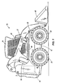
- Fig. 1 illustrates a skid steer loader embodying the present invention.
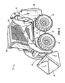
- Fig. 2 illustrates another view of the skid steer loader.
- Fig. 3 is a schematic illustration of a portion of a hydraulic circuit of the skid steer loader.
- Figs. 1 and 2 depict a skid steer loader 10 having a frame 15 supported by four wheels 20, an internal combustion engine 30, an operator compartment 35 that contains an operator control 37, right and left lift arms 40, and a bucket 45 mounted for tilting between the distal ends of the lift arms 40.
- the invention is illustrated embodied in a skid steer loader 10, the invention may be embodied in other vehicles and machines.
- the illustrated operator control 37 takes the form of a joystick, in other embodiments, the control may include multiple joysticks and/or foot pedals.
- the illustrated prime mover for the vehicle is the internal combustion engine 30, other prime movers and sources of energy including but not limited to fuel cells, solar energy, batteries, and corded electric motors may be used in other embodiments.
- the loader 10 moves forward and backward, depending on the direction of rotation of the wheels 20.
- the loader 10 turns on a relatively large radius by rotating the right and left side wheels 20 in the same direction but at different rates, and rotates about a substantially zero turn radius by rotating the right and left side wheels 20 in opposite directions.
- the lift arms 40 raise (i.e., rotate counterclockwise in Fig. 1 ) and lower (i.e., rotate clockwise in Fig. 1 ) with respect to the frame 15 under the influence of lift cylinders 50 mounted between the frame 15 and the lift arms 40.
- the bucket 45 tilts with respect to the arms 40 to curl (i.e., rotate counterclockwise in Fig. 1 ) and dump (i.e., rotate clockwise in Fig. 1 ) under the influence of tilt cylinders 55 mounted between the lift arms 40 and the bucket 45.
- Support links 60 are pivotably mounted between the frame 15 and each lift arm 40 to provide additional support and stability to the lift arms 40.
- Various auxiliary implements or devices may be substituted for or used in conjunction with the bucket 45.
- auxiliary implements includes augers, jack hammers, trenchers, grapples, rotary sweepers, stump grinders, saws, concrete mixers, pumps, chippers, snow throwers, rotary cutters, and backhoes.
- Fig. 3 is a schematic illustration of a portion of a hydraulic circuit 65 of the skid steer loader 10.
- the front and/or rear wheels 20 may be independently rotated by the dedicated hydraulic motors 70.
- Each motor 70 has a motor housing 73.
- Fig. 3 shows only two of the wheels 20 (i.e., the right and left front or rear wheels) being driven by dedicated motors 70, in which case the other two wheels would passively rotate as the skid steer loader 10 moves over ground.
- the skid steer loader 10 includes four dedicated motors 70 to independently drive the four wheels 20.
- each motor 70 and therefore the speed of rotation of the associated wheel 20, is controlled by a two-speed shifting valve 75 that is slidable to increase or decrease the displacement of the motor 70.
- the shifting valve 75 decreases the motor's displacement, it causes the motor 70 to operate (and the associated wheel 20 to rotate) at a faster speed, and when it increases the motor's displacement, it causes the motor 70 to operate (and the associated wheel 20 to rotate) at a slower speed.
- Each shifting valve 75 is biased toward the high displacement, low speed position by a spring 80 in a spring chamber or housing 85.
- the hydraulic system 65 provides a source of pressurized hydraulic fluid 90, which may in some embodiments include one or more hydraulic pumps 95 that are driven by the internal combustion engine 30 (or other prime mover, as may be the case for particular applications), and a control cartridge 100. Although the present invention is described as using the illustrated hydraulic system 65, other embodiments may use motive fluids (e.g., pneumatic or other pressurized fluids) other than hydraulic fluid.
- the control cartridge 100 communicates between the hydraulic pump 95 and the shifting valves 75, to simultaneously control exposure of both shifting valves 75 to the pressurized hydraulic fluid. When the control cartridge 100 exposes the shifting valves 75 to the pressurized hydraulic fluid or motive pressure, the motive pressure shifts the shifting valves 75 from their high displacement (low speed) positions to their low displacement (high speed) positions.
- the cartridge 100 is of the modulated variety, which permits the pressure applied to the shifting valves 75 to ramp up at a rate that causes the motors 70 to shift from low speed to high speed at a relatively slow, controlled rate to increase the operator's comfort while transitioning from low speed to high speed.
- a modulated cartridge may increase pressure on the shifting spool from 0 psi to 200 psi over about a two second period of time, as opposed to a substantially instantaneous time period (e.g., milliseconds) that might result from use of an unmodulated cartridge.
- the present invention includes reference conduits 105 that communicate between the spring chambers 85 and a common receptacle 110, such that both spring chambers 85 are exposed to the same pressure (i.e., the pressure within the receptacle 110).
- the term "receptacle” includes open and closed containers and reservoirs, as well as the atmosphere.
- the reference conduits 105 may, for example, include orifices, apertures, hoses, tubes or pipes that communicate between the spring chambers 85 and a hydraulic return tank or reservoir having a substantially atmospheric pressure, or some other receptacle having an elevated pressure (less than the motive pressure).
- the reference conduits 105 bypass the motor housings 73 of the respective motors 70 to which the spring chambers 85 are associated, so that the spring chambers 85 are not exposed to the inconsistent pressures within those motor housings 73.
- Existing systems may be retrofitted to practice the present invention by plugging the hole or conduit communicating between each spring chamber 85 and the associated motor housing 73, and installing reference conduits 105 to place each spring chamber 85 in communication with a common receptacle 110.
- One of the motor housings 73 may be used as the common receptacle 110 by placing all spring chambers 85 in communication with a single motor housing 73. This could be done by blocking communication between all spring chambers 85 except one and their associated motor housings 73, and placing those spring chambers 85 in communication with the unblocked motor housing 73 by way of reference conduits 105.
- Hydraulic fluid that has leaked into the respective spring chambers 85 drains to the receptacle 110 through the reference conduits 105 and is forced through the conduits 105 as the shifting valves 75 are shifted and the volume of the spring chamber 85 is decreased.
- the conduits 105 have sufficient cross-sectional size to not restrict the flow of fluid out of the spring chambers 85 and into the receptacle 110.
- the backpressure within the spring chambers 85 is about equal to the receptacle pressure 110, regardless of the relative amount of hydraulic fluid that has leaked into one spring chamber 85 compared to the other.
- both shifting valves 75 Deflection of both shifting valves 75 is resisted by a force that is a function of the biasing force of the springs 80 (the springs 80 having substantially identical spring constants and preloads) and the internal pressure of the receptacle 110.
- Such resistance may be, for example and without limitation, proportional to the biasing force of the springs 80 and the internal pressure of the receptacle 110.
- skid steer loader 10 may be modified to include a motor and shifting valve for each of the four wheels 20, in which case the spring chambers 85 of all four shifting valves 75 would be reference to the common receptacle 110 through reference conduits 105.
- Other embodiments may include vehicles other than skid steer loaders that rely on multiple-speed motors to drive two or more of the vehicle's wheels, and a skid steer loader is but one example of a vehicle in which the invention may be embodied.
- rotatable members may be used to broadly encompass wheels, tracks, propellers, fans, paddles, or any other implement that rotates to control the speed and direction of vehicle travel.
- the invention is not limited to coordinating or synchronizing the speed shifting of two-speed motors, and can be used when coordinating or synchronizing the speed shifting of motors having three or more speeds as well.
- the invention may be embodied in applications other than vehicles, provided the application includes a plurality of multiple-speed motors that are desired to be speed shifted in a substantially simultaneous, synchronize manner.
- the invention provides, among other things, a system and method for synchronized speed shifting of multiple motors.
- Various features and advantages of the invention are set forth in the following claims. Attention is directed to all papers and documents which are filed concurrently with or previous to this specification in connection with this application and which are open to public inspection with this specification, and the contents of all such papers and documents are incorporated herein by reference. All of the features disclosed in this specification (including any accompanying claims, abstract and drawings), and/or all of the steps of any method or process so disclosed, may be combined in any combination, except combinations where at least some of such features and/or steps are mutually exclusive. Each feature disclosed in this specification (including any accompanying claims, abstract and drawings) may be replaced by alternative features serving the same, equivalent or similar purpose, unless expressly stated otherwise.
- each feature disclosed is one example only of a generic series of equivalent or similar features.
- the invention is not restricted to the details of the foregoing embodiment(s).
- the invention extends to any novel one, or any novel combination, of the features disclosed in this specification (including any accompanying claims, abstract and drawings), or to any novel one, or any novel combination, of the steps of any method or process so disclosed.
Landscapes
- Engineering & Computer Science (AREA)
- General Engineering & Computer Science (AREA)
- Mechanical Engineering (AREA)
- Physics & Mathematics (AREA)
- Fluid Mechanics (AREA)
- Control Of Fluid Gearings (AREA)
- Operation Control Of Excavators (AREA)
- Fluid-Pressure Circuits (AREA)
- Non-Deflectable Wheels, Steering Of Trailers, Or Other Steering (AREA)
Abstract
Description
- The present invention relates to a system and method for synchronized speed shifting of multiple motors.
- In one embodiment, the invention provides a system comprising: first and second motors; first and second means for shifting speed of the respective first and second motors, each means for shifting being movable between first and second positions corresponding to first and second different speeds of the motors; first and second biasing members, each biasing member positioned within a chamber and biasing one of the first and second means for shifting into the first position; means for substantially simultaneously providing an equal-strength signal to the first and second means for shifting to move the means for shifting from the first position toward the second position; and means for equalizing pressure in the chambers such that resistance to moving each means for shifting from the first position to the second position is substantially equal.
- The invention may be embodied, for example, in a construction vehicle such as a skid steer loader or the like. The motors may be hydraulic motors operating under the influence of a flow of pressurized hydraulic fluid.
- Other aspects of the invention will become apparent by consideration of the detailed description and accompanying drawings.
-
Fig. 1 illustrates a skid steer loader embodying the present invention. -
Fig. 2 illustrates another view of the skid steer loader. -
Fig. 3 is a schematic illustration of a portion of a hydraulic circuit of the skid steer loader. - Before any embodiments of the invention are explained in detail, it is to be understood that the invention is not limited in its application to the details of construction and the arrangement of components set forth in the following description or illustrated in the following drawings. The invention is capable of other embodiments and of being practiced or of being carried out in various ways. Also, it is to be understood that the phraseology and terminology used herein is for the purpose of description and should not be regarded as limiting. The use of "including," "comprising," or "having" and variations thereof herein is meant to encompass the items listed thereafter and equivalents thereof as well as additional items. Unless specified or limited otherwise, the terms "mounted," "connected," "supported," and "coupled" and variations thereof are used broadly and encompass both direct and indirect mountings, connections, supports, and couplings. Further, "connected" and "coupled" are not restricted to physical or mechanical connections or couplings.
-
Figs. 1 and2 depict askid steer loader 10 having aframe 15 supported by fourwheels 20, aninternal combustion engine 30, anoperator compartment 35 that contains anoperator control 37, right andleft lift arms 40, and abucket 45 mounted for tilting between the distal ends of thelift arms 40. Although the invention is illustrated embodied in a skidsteer loader 10, the invention may be embodied in other vehicles and machines. Although the illustratedoperator control 37 takes the form of a joystick, in other embodiments, the control may include multiple joysticks and/or foot pedals. Although the illustrated prime mover for the vehicle is theinternal combustion engine 30, other prime movers and sources of energy including but not limited to fuel cells, solar energy, batteries, and corded electric motors may be used in other embodiments. - When all four
wheels 20 turn at the same speed, theloader 10 moves forward and backward, depending on the direction of rotation of thewheels 20. Theloader 10 turns on a relatively large radius by rotating the right andleft side wheels 20 in the same direction but at different rates, and rotates about a substantially zero turn radius by rotating the right andleft side wheels 20 in opposite directions. - The
lift arms 40 raise (i.e., rotate counterclockwise inFig. 1 ) and lower (i.e., rotate clockwise inFig. 1 ) with respect to theframe 15 under the influence oflift cylinders 50 mounted between theframe 15 and thelift arms 40. Thebucket 45 tilts with respect to thearms 40 to curl (i.e., rotate counterclockwise inFig. 1 ) and dump (i.e., rotate clockwise inFig. 1 ) under the influence oftilt cylinders 55 mounted between thelift arms 40 and thebucket 45.Support links 60 are pivotably mounted between theframe 15 and eachlift arm 40 to provide additional support and stability to thelift arms 40. Various auxiliary implements or devices may be substituted for or used in conjunction with thebucket 45. An example, but by no means exhaustive, list of auxiliary implements includes augers, jack hammers, trenchers, grapples, rotary sweepers, stump grinders, saws, concrete mixers, pumps, chippers, snow throwers, rotary cutters, and backhoes. -
Fig. 3 is a schematic illustration of a portion of ahydraulic circuit 65 of theskid steer loader 10. Depending on how thehydraulic system 65 is configured, the front and/orrear wheels 20 may be independently rotated by the dedicatedhydraulic motors 70. Eachmotor 70 has amotor housing 73. For the sake of illustration,Fig. 3 shows only two of the wheels 20 (i.e., the right and left front or rear wheels) being driven bydedicated motors 70, in which case the other two wheels would passively rotate as theskid steer loader 10 moves over ground. In a preferred commercial embodiment, theskid steer loader 10 includes fourdedicated motors 70 to independently drive the fourwheels 20. - The speed of each
motor 70, and therefore the speed of rotation of the associatedwheel 20, is controlled by a two-speed shifting valve 75 that is slidable to increase or decrease the displacement of themotor 70. When the shiftingvalve 75 decreases the motor's displacement, it causes themotor 70 to operate (and the associatedwheel 20 to rotate) at a faster speed, and when it increases the motor's displacement, it causes themotor 70 to operate (and theassociated wheel 20 to rotate) at a slower speed. Each shiftingvalve 75 is biased toward the high displacement, low speed position by aspring 80 in a spring chamber orhousing 85. - The
hydraulic system 65 provides a source of pressurizedhydraulic fluid 90, which may in some embodiments include one or morehydraulic pumps 95 that are driven by the internal combustion engine 30 (or other prime mover, as may be the case for particular applications), and acontrol cartridge 100. Although the present invention is described as using the illustratedhydraulic system 65, other embodiments may use motive fluids (e.g., pneumatic or other pressurized fluids) other than hydraulic fluid. Thecontrol cartridge 100 communicates between thehydraulic pump 95 and the shiftingvalves 75, to simultaneously control exposure of both shiftingvalves 75 to the pressurized hydraulic fluid. When thecontrol cartridge 100 exposes the shiftingvalves 75 to the pressurized hydraulic fluid or motive pressure, the motive pressure shifts the shiftingvalves 75 from their high displacement (low speed) positions to their low displacement (high speed) positions. In some embodiments, thecartridge 100 is of the modulated variety, which permits the pressure applied to the shiftingvalves 75 to ramp up at a rate that causes themotors 70 to shift from low speed to high speed at a relatively slow, controlled rate to increase the operator's comfort while transitioning from low speed to high speed. For example, a modulated cartridge may increase pressure on the shifting spool from 0 psi to 200 psi over about a two second period of time, as opposed to a substantially instantaneous time period (e.g., milliseconds) that might result from use of an unmodulated cartridge. - In many known systems, hydraulic fluid leaks into the
spring chambers 85 and is drained into themotor housing 73 of themotor 70 associated with thespring chamber 85. Thespring chambers 85 of such known systems are therefore exposed to the pressure within the associatedmotor housing 73. Onemotor housing 73 will in many instances have an internal pressure different from theother motor housing 73 within the system, due to different operating modes and conditions of themotors 70. Therefore, despite thecartridge 100 providing an identical, synchronized pressure signal to the shiftingvalves 75, the shiftingvalve 75 having a lower backpressure in its associatedspring chamber 85 will shift more quickly than the other shiftingvalve 75, which results in the associatedmotors 70 shifting between speeds at different times. During the lag between bothmotors 70 being at the first speed and bothmotors 70 achieving the second speed, thewheels 70 are driven at different speeds, which results in the vehicle drifting off its line of travel as the speed is shifted. - To better synchronize actuation of the shifting
valves 75, the present invention includesreference conduits 105 that communicate between thespring chambers 85 and acommon receptacle 110, such that bothspring chambers 85 are exposed to the same pressure (i.e., the pressure within the receptacle 110). For the purposes of describing this invention, the term "receptacle" includes open and closed containers and reservoirs, as well as the atmosphere. Thereference conduits 105 may, for example, include orifices, apertures, hoses, tubes or pipes that communicate between thespring chambers 85 and a hydraulic return tank or reservoir having a substantially atmospheric pressure, or some other receptacle having an elevated pressure (less than the motive pressure). Thereference conduits 105 bypass themotor housings 73 of therespective motors 70 to which thespring chambers 85 are associated, so that thespring chambers 85 are not exposed to the inconsistent pressures within thosemotor housings 73. - Existing systems may be retrofitted to practice the present invention by plugging the hole or conduit communicating between each
spring chamber 85 and the associatedmotor housing 73, and installingreference conduits 105 to place eachspring chamber 85 in communication with acommon receptacle 110. One of themotor housings 73 may be used as thecommon receptacle 110 by placing allspring chambers 85 in communication with asingle motor housing 73. This could be done by blocking communication between allspring chambers 85 except one and their associatedmotor housings 73, and placing thosespring chambers 85 in communication with theunblocked motor housing 73 by way ofreference conduits 105. - Hydraulic fluid that has leaked into the
respective spring chambers 85 drains to thereceptacle 110 through thereference conduits 105 and is forced through theconduits 105 as the shiftingvalves 75 are shifted and the volume of thespring chamber 85 is decreased. Theconduits 105 have sufficient cross-sectional size to not restrict the flow of fluid out of thespring chambers 85 and into thereceptacle 110. The backpressure within thespring chambers 85 is about equal to thereceptacle pressure 110, regardless of the relative amount of hydraulic fluid that has leaked into onespring chamber 85 compared to the other. Deflection of both shiftingvalves 75 is resisted by a force that is a function of the biasing force of the springs 80 (thesprings 80 having substantially identical spring constants and preloads) and the internal pressure of thereceptacle 110. Such resistance may be, for example and without limitation, proportional to the biasing force of thesprings 80 and the internal pressure of thereceptacle 110. - Although the present invention has been described and illustrated with reference to a skid
steer loader 10 application, it is capable of being embodied in many different applications which seek to synchronize speed shifting of two or more multiple-speed motors. For example, the illustrated and described skidsteer loader 10 may be modified to include a motor and shifting valve for each of the fourwheels 20, in which case thespring chambers 85 of all four shiftingvalves 75 would be reference to thecommon receptacle 110 throughreference conduits 105. Other embodiments may include vehicles other than skid steer loaders that rely on multiple-speed motors to drive two or more of the vehicle's wheels, and a skid steer loader is but one example of a vehicle in which the invention may be embodied. The vehicle need not have wheels, as in the case of a compact track vehicle. In this regard, the term "rotatable members" may be used to broadly encompass wheels, tracks, propellers, fans, paddles, or any other implement that rotates to control the speed and direction of vehicle travel. - Also, the invention is not limited to coordinating or synchronizing the speed shifting of two-speed motors, and can be used when coordinating or synchronizing the speed shifting of motors having three or more speeds as well. In a broader sense, the invention may be embodied in applications other than vehicles, provided the application includes a plurality of multiple-speed motors that are desired to be speed shifted in a substantially simultaneous, synchronize manner.
- Thus, the invention provides, among other things, a system and method for synchronized speed shifting of multiple motors. Various features and advantages of the invention are set forth in the following claims.
Attention is directed to all papers and documents which are filed concurrently with or previous to this specification in connection with this application and which are open to public inspection with this specification, and the contents of all such papers and documents are incorporated herein by reference.
All of the features disclosed in this specification (including any accompanying claims, abstract and drawings), and/or all of the steps of any method or process so disclosed, may be combined in any combination, except combinations where at least some of such features and/or steps are mutually exclusive.
Each feature disclosed in this specification (including any accompanying claims, abstract and drawings) may be replaced by alternative features serving the same, equivalent or similar purpose, unless expressly stated otherwise. Thus, unless expressly stated otherwise, each feature disclosed is one example only of a generic series of equivalent or similar features.
The invention is not restricted to the details of the foregoing embodiment(s). The invention extends to any novel one, or any novel combination, of the features disclosed in this specification (including any accompanying claims, abstract and drawings), or to any novel one, or any novel combination, of the steps of any method or process so disclosed.
Claims (9)
- A system comprising:first and second motors;first and second means for shifting speed of the respective first and second motors, each means for shifting being movable between first and second positions corresponding to first and second different speeds of the motors;first and second biasing members, each biasing member positioned within a chamber and biasing one of the first and second means for shifting into the first position;means for substantially simultaneously providing an equal-strength signal to the first and second means for shifting to move the means for shifting from the first position toward the second position; andmeans for equalizing pressure in the chambers such that resistance to moving each means for shifting from the first position to the second position is substantially equal.
- The system of claim 1, wherein each of the first and second means for shifting includes a valve shiftable to change the displacement of the respective first and second motors.
- The system of claim 1, further comprising a source of pressurized fluid; wherein the means for providing an equal-strength signal includes a cartridge adapted to simultaneously expose the first and second means for shifting to the pressurized fluid.
- The system of claim 3, wherein the means for providing an equal-strength signal further includes a modulator to ramp the exposure of pressurized fluid to the first and second means for shifting.
- The system of claim 1, further comprising a receptacle having an internal pressure; wherein the means for equalizing pressure includes first and second conduits placing the chambers in communication with the receptacle.
- A construction vehicle comprising:a frame;a plurality of rotatable members rotatably mounted with respect to the frame and rotatable to control the speed and direction of vehicle travel;a prime mover supported by the frame;a source of pressurized fluid driven by the prime mover to create a flow of pressurized fluid;a plurality of motors operable in response to the flow of pressurized fluid from the source, each motor being interconnected to an associated rotatable member to drive rotation of the associated rotatable member;a speed shifting valve associated with each motor and movable between first and second positions corresponding to first and second different speeds of the associated motor;a biasing member in a chamber associated with each speed shifting valve, each biasing member biasing the associated speed shifting valve into the first position;a mechanism for substantially simultaneously exposing all of the speed shifting valves to the pressurized fluid;a receptacle having an internal pressure; anda plurality of reference conduits placing the chambers in fluid communication with the receptacle such that pressure within each chamber is substantially equal to the internal pressure of the receptacle.
- The vehicle of claim 6, wherein the rotatable members include wheels; wherein the prime mover includes an internal combustion engine; and wherein the source of pressurized fluid includes a hydraulic pump driven by the internal combustion engine.
- The vehicle of claim 7, further comprising a lift arm, an auxiliary implement supported by the lift arm, a lift cylinder for raising the lift arm with respect to the frame, and a tilt cylinder for pivoting the implement with respect to the lift arm, wherein the hydraulic pump provides pressurized fluid to the lift and tilt cylinders.
- A method for synchronizing speed shifting of a plurality of motors, the motors including speed shifting valves shiftable under the influence of a motive pressure, and biasing members in chambers and biasing the speed shifting valves into a first position corresponding to a first motor speed, the method comprising the steps of:(a) fluidly communicating all chambers with a single receptacle having an internal pressure;(b) substantially simultaneously applying an equal shifting force to each of the speed shifting valves to move the speed shifting valves into a second position corresponding to a second motor speed different from the first; and(c) resisting shifting of each speed shifting valve with a substantially equal force that is a function of the biasing force and the internal pressure of the receptacle.
Applications Claiming Priority (1)
| Application Number | Priority Date | Filing Date | Title |
|---|---|---|---|
| US11/619,544 US7571605B2 (en) | 2007-01-03 | 2007-01-03 | Synchronized speed shifting of multiple motors |
Publications (2)
| Publication Number | Publication Date |
|---|---|
| EP2017503A2 true EP2017503A2 (en) | 2009-01-21 |
| EP2017503A3 EP2017503A3 (en) | 2011-02-23 |
Family
ID=39584822
Family Applications (1)
| Application Number | Title | Priority Date | Filing Date |
|---|---|---|---|
| EP07253007A Withdrawn EP2017503A3 (en) | 2007-01-03 | 2007-07-31 | Synchronized speed shifting of multiple motors |
Country Status (4)
| Country | Link |
|---|---|
| US (1) | US7571605B2 (en) |
| EP (1) | EP2017503A3 (en) |
| CN (1) | CN101216054B (en) |
| CA (1) | CA2598061A1 (en) |
Families Citing this family (2)
| Publication number | Priority date | Publication date | Assignee | Title |
|---|---|---|---|---|
| DE102012020984A1 (en) * | 2012-10-25 | 2014-04-30 | Liebherr-Hydraulikbagger Gmbh | Device for driving speed control of a work vehicle and method therefor |
| US9139981B2 (en) * | 2014-02-06 | 2015-09-22 | Caterpillar Inc. | Rimpull Derate management in a machine with independent powertrains |
Citations (1)
| Publication number | Priority date | Publication date | Assignee | Title |
|---|---|---|---|---|
| US4554991A (en) | 1984-02-23 | 1985-11-26 | Mud Hog Corporation | Auxiliary hydraulic drive system for road graders and the like |
Family Cites Families (7)
| Publication number | Priority date | Publication date | Assignee | Title |
|---|---|---|---|---|
| DE2522719C2 (en) * | 1975-05-22 | 1986-06-05 | Linde Ag, 6200 Wiesbaden | Control device |
| US4402181A (en) * | 1980-12-10 | 1983-09-06 | Allis-Chalmers Corporation | Hydraulic drive system for a vehicle |
| JP2520314B2 (en) * | 1990-01-18 | 1996-07-31 | 株式会社小松製作所 | Travel speed switching device for hydraulic excavator |
| JPH0745652Y2 (en) * | 1990-03-09 | 1995-10-18 | 新キャタピラー三菱株式会社 | Travel speed switching device |
| US6857494B2 (en) * | 2000-09-06 | 2005-02-22 | Komatsu Ltd. | Steering-wheel revolution number correction system of all-wheel-drive vehicle |
| US6609368B2 (en) * | 2001-06-04 | 2003-08-26 | Caterpillar S.A.R.L. | Automatic downshift and override control for a transmission |
| KR101155718B1 (en) * | 2004-12-31 | 2012-06-12 | 두산인프라코어 주식회사 | An apparatus for controlling the starting speed of an excavator |
-
2007
- 2007-01-03 US US11/619,544 patent/US7571605B2/en not_active Expired - Fee Related
- 2007-07-31 EP EP07253007A patent/EP2017503A3/en not_active Withdrawn
- 2007-08-21 CA CA002598061A patent/CA2598061A1/en not_active Abandoned
- 2007-11-13 CN CN200710168154.1A patent/CN101216054B/en not_active Expired - Fee Related
Patent Citations (1)
| Publication number | Priority date | Publication date | Assignee | Title |
|---|---|---|---|---|
| US4554991A (en) | 1984-02-23 | 1985-11-26 | Mud Hog Corporation | Auxiliary hydraulic drive system for road graders and the like |
Also Published As
| Publication number | Publication date |
|---|---|
| CN101216054B (en) | 2013-05-08 |
| CA2598061A1 (en) | 2008-07-03 |
| EP2017503A3 (en) | 2011-02-23 |
| US20080161152A1 (en) | 2008-07-03 |
| US7571605B2 (en) | 2009-08-11 |
| CN101216054A (en) | 2008-07-09 |
Similar Documents
| Publication | Publication Date | Title |
|---|---|---|
| CA2679998C (en) | Hydraulic power management system | |
| US20140023523A1 (en) | Closed loop drive circuit with external brake assist | |
| WO2007111158A1 (en) | Wheel loader | |
| WO2012145208A2 (en) | Overrunning pump protection for flow-controlled actuators | |
| JPH01105828A (en) | Selfpropelling working vehicle | |
| WO2008150538A1 (en) | Steering with parallel - series connection of two speed motors | |
| WO2012107186A1 (en) | Hydrostatic system configured to be integrated in an excavator | |
| US20140069092A1 (en) | Traction Control System for a Hydrostatic Drive | |
| EP2855944B1 (en) | Control valve assembly | |
| US20170037602A1 (en) | Hydraulic System for an Earth Moving Machine | |
| KR19980063733A (en) | Compact excavator with improved valve placement | |
| JP2018108806A (en) | Working machine hydraulic system | |
| EP2017503A2 (en) | Synchronized speed shifting of multiple motors | |
| JP7179683B2 (en) | Hydraulic system of work equipment | |
| JP7210651B2 (en) | Hydraulic system of work equipment | |
| WO2001086173A1 (en) | Hydraulic pump circuit for mini excavators | |
| JP6847821B2 (en) | Work machine hydraulic system | |
| CN112523280B (en) | working machine | |
| US9429174B1 (en) | Enabling valve having separate float and lift down positions | |
| JP6766030B2 (en) | Work machine hydraulic system | |
| JP4481264B2 (en) | Wheel brake autobrake method and wheel loader | |
| EP2971871A1 (en) | Control system for variable displacement hydraulic motor | |
| JP4392142B2 (en) | Hydraulic equipment for excavating and turning work vehicle | |
| JP4481265B2 (en) | Wheel loader |
Legal Events
| Date | Code | Title | Description |
|---|---|---|---|
| PUAI | Public reference made under article 153(3) epc to a published international application that has entered the european phase |
Free format text: ORIGINAL CODE: 0009012 |
|
| AK | Designated contracting states |
Kind code of ref document: A2 Designated state(s): AT BE BG CH CY CZ DE DK EE ES FI FR GB GR HU IE IS IT LI LT LU LV MC MT NL PL PT RO SE SI SK TR |
|
| AX | Request for extension of the european patent |
Extension state: AL BA HR MK RS |
|
| PUAL | Search report despatched |
Free format text: ORIGINAL CODE: 0009013 |
|
| AK | Designated contracting states |
Kind code of ref document: A3 Designated state(s): AT BE BG CH CY CZ DE DK EE ES FI FR GB GR HU IE IS IT LI LT LU LV MC MT NL PL PT RO SE SI SK TR |
|
| AX | Request for extension of the european patent |
Extension state: AL BA HR MK RS |
|
| RIC1 | Information provided on ipc code assigned before grant |
Ipc: F16H 61/456 20100101ALI20110119BHEP Ipc: F16H 61/423 20100101AFI20110119BHEP |
|
| 17P | Request for examination filed |
Effective date: 20110823 |
|
| AKX | Designation fees paid |
Designated state(s): DE ES FR GB IT |
|
| 17Q | First examination report despatched |
Effective date: 20111025 |
|
| GRAP | Despatch of communication of intention to grant a patent |
Free format text: ORIGINAL CODE: EPIDOSNIGR1 |
|
| STAA | Information on the status of an ep patent application or granted ep patent |
Free format text: STATUS: THE APPLICATION IS DEEMED TO BE WITHDRAWN |
|
| 18D | Application deemed to be withdrawn |
Effective date: 20121003 |