EP2017440B1 - Method for manufacturing a silencer device and an apparatus for manufacturing said device - Google Patents
Method for manufacturing a silencer device and an apparatus for manufacturing said device Download PDFInfo
- Publication number
- EP2017440B1 EP2017440B1 EP08159563A EP08159563A EP2017440B1 EP 2017440 B1 EP2017440 B1 EP 2017440B1 EP 08159563 A EP08159563 A EP 08159563A EP 08159563 A EP08159563 A EP 08159563A EP 2017440 B1 EP2017440 B1 EP 2017440B1
- Authority
- EP
- European Patent Office
- Prior art keywords
- conduit
- parison
- orifices
- moulds
- mould
- Prior art date
- Legal status (The legal status is an assumption and is not a legal conclusion. Google has not performed a legal analysis and makes no representation as to the accuracy of the status listed.)
- Not-in-force
Links
- 230000003584 silencer Effects 0.000 title claims abstract description 30
- 238000004519 manufacturing process Methods 0.000 title claims abstract description 10
- 238000000034 method Methods 0.000 title claims description 21
- 239000012530 fluid Substances 0.000 claims abstract description 12
- 238000004891 communication Methods 0.000 claims abstract description 5
- 230000000712 assembly Effects 0.000 claims description 11
- 238000000429 assembly Methods 0.000 claims description 11
- 238000000071 blow moulding Methods 0.000 claims description 10
- 238000007664 blowing Methods 0.000 claims description 6
- 239000000463 material Substances 0.000 claims description 6
- 239000004033 plastic Substances 0.000 claims description 5
- 229920003023 plastic Polymers 0.000 claims description 5
- 230000035515 penetration Effects 0.000 claims description 3
- 238000002485 combustion reaction Methods 0.000 abstract description 11
- 239000007789 gas Substances 0.000 description 3
- 239000004952 Polyamide Substances 0.000 description 2
- 239000004743 Polypropylene Substances 0.000 description 2
- 238000005516 engineering process Methods 0.000 description 2
- 229920002647 polyamide Polymers 0.000 description 2
- 238000004804 winding Methods 0.000 description 2
- 229920002943 EPDM rubber Polymers 0.000 description 1
- 238000004026 adhesive bonding Methods 0.000 description 1
- 238000005520 cutting process Methods 0.000 description 1
- 230000001066 destructive effect Effects 0.000 description 1
- 238000010586 diagram Methods 0.000 description 1
- 238000007599 discharging Methods 0.000 description 1
- 229920001971 elastomer Polymers 0.000 description 1
- 239000004744 fabric Substances 0.000 description 1
- 238000000465 moulding Methods 0.000 description 1
- 239000002245 particle Substances 0.000 description 1
- 229920000728 polyester Polymers 0.000 description 1
- -1 polypropylene Polymers 0.000 description 1
- 229920001155 polypropylene Polymers 0.000 description 1
- 230000001902 propagating effect Effects 0.000 description 1
- 238000004064 recycling Methods 0.000 description 1
- 239000005060 rubber Substances 0.000 description 1
- 238000005476 soldering Methods 0.000 description 1
- 229920001169 thermoplastic Polymers 0.000 description 1
- 229920002725 thermoplastic elastomer Polymers 0.000 description 1
- 239000012815 thermoplastic material Substances 0.000 description 1
- 239000004416 thermosoftening plastic Substances 0.000 description 1
- XLYOFNOQVPJJNP-UHFFFAOYSA-N water Substances O XLYOFNOQVPJJNP-UHFFFAOYSA-N 0.000 description 1
Images


Classifications
-
- F—MECHANICAL ENGINEERING; LIGHTING; HEATING; WEAPONS; BLASTING
- F02—COMBUSTION ENGINES; HOT-GAS OR COMBUSTION-PRODUCT ENGINE PLANTS
- F02M—SUPPLYING COMBUSTION ENGINES IN GENERAL WITH COMBUSTIBLE MIXTURES OR CONSTITUENTS THEREOF
- F02M35/00—Combustion-air cleaners, air intakes, intake silencers, or induction systems specially adapted for, or arranged on, internal-combustion engines
- F02M35/10—Air intakes; Induction systems
- F02M35/10242—Devices or means connected to or integrated into air intakes; Air intakes combined with other engine or vehicle parts
- F02M35/10295—Damping means, e.g. tranquillising chamber to dampen air oscillations
-
- F—MECHANICAL ENGINEERING; LIGHTING; HEATING; WEAPONS; BLASTING
- F02—COMBUSTION ENGINES; HOT-GAS OR COMBUSTION-PRODUCT ENGINE PLANTS
- F02M—SUPPLYING COMBUSTION ENGINES IN GENERAL WITH COMBUSTIBLE MIXTURES OR CONSTITUENTS THEREOF
- F02M35/00—Combustion-air cleaners, air intakes, intake silencers, or induction systems specially adapted for, or arranged on, internal-combustion engines
- F02M35/10—Air intakes; Induction systems
- F02M35/10006—Air intakes; Induction systems characterised by the position of elements of the air intake system in direction of the air intake flow, i.e. between ambient air inlet and supply to the combustion chamber
- F02M35/10013—Means upstream of the air filter; Connection to the ambient air
-
- F—MECHANICAL ENGINEERING; LIGHTING; HEATING; WEAPONS; BLASTING
- F02—COMBUSTION ENGINES; HOT-GAS OR COMBUSTION-PRODUCT ENGINE PLANTS
- F02M—SUPPLYING COMBUSTION ENGINES IN GENERAL WITH COMBUSTIBLE MIXTURES OR CONSTITUENTS THEREOF
- F02M35/00—Combustion-air cleaners, air intakes, intake silencers, or induction systems specially adapted for, or arranged on, internal-combustion engines
- F02M35/10—Air intakes; Induction systems
- F02M35/10091—Air intakes; Induction systems characterised by details of intake ducts: shapes; connections; arrangements
-
- F—MECHANICAL ENGINEERING; LIGHTING; HEATING; WEAPONS; BLASTING
- F02—COMBUSTION ENGINES; HOT-GAS OR COMBUSTION-PRODUCT ENGINE PLANTS
- F02M—SUPPLYING COMBUSTION ENGINES IN GENERAL WITH COMBUSTIBLE MIXTURES OR CONSTITUENTS THEREOF
- F02M35/00—Combustion-air cleaners, air intakes, intake silencers, or induction systems specially adapted for, or arranged on, internal-combustion engines
- F02M35/12—Intake silencers ; Sound modulation, transmission or amplification
- F02M35/1205—Flow throttling or guiding
- F02M35/1238—Flow throttling or guiding by using secondary connections to the ambient, e.g. covered by a membrane or a porous member
-
- F—MECHANICAL ENGINEERING; LIGHTING; HEATING; WEAPONS; BLASTING
- F02—COMBUSTION ENGINES; HOT-GAS OR COMBUSTION-PRODUCT ENGINE PLANTS
- F02B—INTERNAL-COMBUSTION PISTON ENGINES; COMBUSTION ENGINES IN GENERAL
- F02B37/00—Engines characterised by provision of pumps driven at least for part of the time by exhaust
-
- F—MECHANICAL ENGINEERING; LIGHTING; HEATING; WEAPONS; BLASTING
- F02—COMBUSTION ENGINES; HOT-GAS OR COMBUSTION-PRODUCT ENGINE PLANTS
- F02M—SUPPLYING COMBUSTION ENGINES IN GENERAL WITH COMBUSTIBLE MIXTURES OR CONSTITUENTS THEREOF
- F02M35/00—Combustion-air cleaners, air intakes, intake silencers, or induction systems specially adapted for, or arranged on, internal-combustion engines
- F02M35/16—Combustion-air cleaners, air intakes, intake silencers, or induction systems specially adapted for, or arranged on, internal-combustion engines characterised by use in vehicles
- F02M35/165—Marine vessels; Ships; Boats
- F02M35/167—Marine vessels; Ships; Boats having outboard engines; Jet-skis
- F02M35/168—Marine vessels; Ships; Boats having outboard engines; Jet-skis with means, e.g. valves, to prevent water entry
Definitions
- the present invention concerns a method and apparatus for manufacturing silencer device in a single piece with a fluid conduit.
- the invention concerns a silencer device for intake conduits of air intake systems in internal combustion engines, in particular engines for vehicles and especially motor vehicles.
- silencer devices In the field of internal combustion engines, for instance engines for vehicles and in particular motor vehicles, silencer devices have been developed aiming at reducing the noise level associated with exhaust gas discharge from and air intake into the engine.
- Intake silencer generally operates by exploding the principle of destructive interference and, in its simplest form, it consists of an expansion chamber and two hoses with such shapes and sizes that air passes therethrough with minimum noise.
- modem internal combustion engines especially diesel cycle engines
- turbocharger In order to reduce the amount of harmful emissions and to increase the delivered power, modem internal combustion engines, especially diesel cycle engines, are generally equipped with a turbocharger and nowadays they are fed with air at higher and higher pressure.
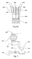
- Fig. 7 shows a scheme of a conventional intake system for supercharged internal combustion engines.
- An engine MT is equipped with an exhaust manifold CR for discharging exhaust gases, and an intake manifold CA for air inlet into the combustion chambers.
- Intake manifold CA receives air from intake system AS that preferably includes a heat exchanger SC, generally of the air-to-air type, known as "intercooler” device, a turbine TR or turbocharger, generally operated by the exhaust gases, and a filter FT, for instance equipped with a cartridge of corrugated paper, which removes particles with too big a size, which could damage the engine, from the inlet air flow.
- Air arriving at filter FT is taken from the external environment through an intake conduit CS having an intake mouth BS.
- the intake mouth is to be suitably positioned in order to prevent entrance of foreign bodies.
- intake conduit CS will have different shapes and will often be winding, whereby application of conventional silencer devices will consequently be difficult.
- FR 2 867 234 discloses an acoustic attenuation device, particularly for an intake duct of an internal combustion engine. This document discloses the manufacturing of the intake duct by forming apertures on such duct during a blow moulding process.
- An advantage of the invention is the possibility of equipping any conduit with the silencer device, thereby obtaining an integral body having no connecting joint.
- the device could be applied only on one or some conduit portions. More particularly, the orifices could be provided only in the conduit portions that are less subject to smearing, whereby the performance of the silencer device is preserved in time.
- the reduction of the number of components further allows reducing the weight and results in a greater capability of recycling materials.
- the method according to the invention can be implemented by using the conventional technologies for producing fluid conduits.
- FIG. 1 the principle on which a silencer device manufactured by the method and apparatus according to the present invention is based is schematically shown.
- said conduit 11 further has a set of orifices 19 along wall 13 defining conduit 11 itself, said orifices putting the inside of the conduit in communication with the outside.
- the present invention is based on the discovery that such a physical principle can be advantageously applied to produce silencer devices for conduits along which a fluid, in particular a gaseous fluid, flows, in order to reduce the noise produced by the pressure variations the fluid is subjected to, in particular the variations due to the fluid inflow into the conduit and to the shape of the conduit itself.
- the silencer device manufactured by the method and apparatus according to the present invention comprises a dissipating element, which has at least two and preferably at least four orifices and is formed or applied at least in correspondence of a portion of the wall defining the conduit, said orifices putting the inside of the conduit in communication with the outside.
- Said device will preferably be formed directly integrated into the conduit wall, which therefore will have orifices in at least a portion thereof, but it can also be made by applying, for instance in correspondence of a window formed on the conduit wall, a body having orifices.
- the silencer device thus obtained advantageously allows cutting down the noise propagating along the conduit.
- Said device can be applied in particular in the conduits of the intake system of internal combustion engines, for instance engines used in vehicles.
- a generic conduit 211 defined by a wall 213 and having an inlet mouth 215 and an outlet mouth 217, includes said silencer device 221 consisting of an element 223 with a plurality of orifices 219. which is directly formed on wall 213 of conduit 211.
- silencer device 221 is formed in correspondence of one side of a curved portion of conduit 211, and it can be seen through the section made in the Figure on the opposite side.
- monolithic conduits of a material homogeneous with the integrated silencer device can be produced, and the device can extend over the whole or part of the surface of the wall defining the conduit.
- a generic conduit 311 defined by a wall 313 and having an inlet mouth 315 and an outlet mouth 317, includes a silencer device 321 consisting of an element 323 with a plurality of orifices 319, which is applied on wall 313 of conduit 311, for instance by soldering or gluing, in correspondence of a window 325 formed on the wall of said conduit.
- silencer device 321 is applied in correspondence of one side of a curved portion of conduit 311, corresponding to the front side that can be seen in the Figure.
- existing conduits can be equipped with the silencer device, which can be a separate body applied to the conduit wall or a hose inserted between two successive sections of the same conduit or of different conduits.
- FIG. 4 there is shown a generic intake conduit 411 for a turbocharged diesel cycle internal combustion engine for a motor vehicle, which conduit has been equipped with a silencer device 421 manufactured by the method and apparatus according to the invention.
- Conduit 411 is of the kind associated with the intake system in the initial portion conveying fresh air from the external environment towards the filter.
- Said conduit 411 is defined by a wall 413 and has an inlet mouth 415 and an outlet mouth 417.
- Conduit 411 has a winding shape and is equipped with at least one bellows 429 integrated into conduit wall 413.
- wall 413 of conduit 411 has orifices 419, highlighted in the enlarged portion of Fig. 4 , which are distributed over a portion 423 of wall 413.
- Said orifices are formed by piercing wall 413 and they have a diameter "d" of about 0.8 mm and a pitch "p" of about 4.0 mm.
- conduit 411 can advantageously be made of plastics, preferably as an integral piece, and orifices 419 are formed in wall 413 either while conduit 411 is being formed.
- the silencer device manufactured by the method and apparatus according to the invention is directly formed on the wall of a fluid conduit by piercing, in at least one conduit portion, at least two and preferably at least four circular micro-orifices with a diameter lower than 5.0 mm and preferably ranging from about 0.5 to 1.5 mm, and with a pitch of the order of some millimetres, e.g. ranging from 1 to 10 mm and preferably of about 4.0 mm.
- the conduit is made of a thermoplastic material, e.g. thermoplastic polyester (TEEE) or rigid-soft polyamide (PA) or polypropylene (GF) and thermoplastic rubber (PPGF + PP/EPDM).
- TEEE thermoplastic polyester
- PA rigid-soft polyamide
- GF polypropylene
- PPGF + PP/EPDM thermoplastic rubber
- such materials enable dispensing with the use of non-recyclable materials, such as rubber, while reducing at the same time the weights.
- the manufacture of the conduit takes place by exploiting the blow-moulding technology, which, among its main advantages, enables manufacturing special products having a complex geometry and combining, in a single piece, characteristics of stiffness, resilience and capability of deformation with high dimensional precision and stability.
- the parison is then clenched between the half-moulds and compressed air is blown into the clenched parison that expands until taking the shape of the mould cavity.
- the blow-moulding process comprises therefore the steps of: placing the parison in the half-mould; closing the mould; blowing; removing the formed piece.
- At least one of half-moulds 551 of a machine for blow-moulding plastics is equipped with a piercing assembly 553.
- said piercing assembly 553 comprises a support 555 slidable in a seat 556 formed in the half-mould body, thanks to a control unit 557 for instance of pneumatic type.
- a support 555 has associated therewith needles 559 that, when sliding, jointly with support 555, in corresponding seats 561 formed in the body of half-mould 551, penetrate during blowing into the body of parison 563, a portion of which can be seen, and enable forming corresponding orifices on the wall of the conduit obtained at the end of the blowing step.
- piercing assembly 553 has nine needles 559 in order to pierce an equal number of holes into parison 563, which holes have axes substantially perpendicular to the wall of the conduit obtained by moulding the parison.
- piercing assemblies with a different number of needles and/or multiple piercing assemblies in one or both half-moulds, and even with different penetration directions, can be envisaged.
- the piercing assembly (assemblies) are pneumatically controlled while the parison blowing takes place.
Landscapes
- Engineering & Computer Science (AREA)
- Chemical & Material Sciences (AREA)
- Combustion & Propulsion (AREA)
- Mechanical Engineering (AREA)
- General Engineering & Computer Science (AREA)
- Exhaust Silencers (AREA)
Abstract
Description
- The present invention concerns a method and apparatus for manufacturing silencer device in a single piece with a fluid conduit.
- More precisely, the invention concerns a silencer device for intake conduits of air intake systems in internal combustion engines, in particular engines for vehicles and especially motor vehicles.
- In the field of internal combustion engines, for instance engines for vehicles and in particular motor vehicles, silencer devices have been developed aiming at reducing the noise level associated with exhaust gas discharge from and air intake into the engine.
- Thus, in such field, two kinds of silencer devices are generally known, namely the exhaust silencer and the intake silencer.
- Intake silencer generally operates by exploding the principle of destructive interference and, in its simplest form, it consists of an expansion chamber and two hoses with such shapes and sizes that air passes therethrough with minimum noise.
- In order to reduce the amount of harmful emissions and to increase the delivered power, modem internal combustion engines, especially diesel cycle engines, are generally equipped with a turbocharger and nowadays they are fed with air at higher and higher pressure.
- For that reason, noise associated with air inlet into the intake manifold of such supercharged engines has consequently significantly increased.
-
Fig. 7 shows a scheme of a conventional intake system for supercharged internal combustion engines. - An engine MT is equipped with an exhaust manifold CR for discharging exhaust gases, and an intake manifold CA for air inlet into the combustion chambers.
- Intake manifold CA receives air from intake system AS that preferably includes a heat exchanger SC, generally of the air-to-air type, known as "intercooler" device, a turbine TR or turbocharger, generally operated by the exhaust gases, and a filter FT, for instance equipped with a cartridge of corrugated paper, which removes particles with too big a size, which could damage the engine, from the inlet air flow. Air arriving at filter FT is taken from the external environment through an intake conduit CS having an intake mouth BS.
- As known, the intake mouth is to be suitably positioned in order to prevent entrance of foreign bodies.
- In certain applications, especially in the vehicle field, due to the arrangement of the engine and its components and to the need to properly position the intake mouth, for instance to prevent water entrance during travel, intake conduit CS will have different shapes and will often be winding, whereby application of conventional silencer devices will consequently be difficult.
- In the past, silenced conduits made of reinforced fabric have been developed, which however have the drawback of being heavy and expensive and of demanding connecting joints in order they are associated with the remaining portions of the intake system.
-
FR 2 867 234 - It is an object of the invention to provide a simple and cheap method and apparatus for producing the silencer device in a single piece with a fluid conduit.
- The above and other objects are achieved as claimed in the appended claims.
- Advantageously, thanks to the provision of some orifices in the conduit wall, it is possible to cut down the noise level generated by pressure variations of the fluid flowing along the conduit.
- An advantage of the invention is the possibility of equipping any conduit with the silencer device, thereby obtaining an integral body having no connecting joint.
- Advantageously, according to the invention, the device could be applied only on one or some conduit portions. More particularly, the orifices could be provided only in the conduit portions that are less subject to smearing, whereby the performance of the silencer device is preserved in time.
- Further advantages of the invention, which are mainly related with the possibility of integrating the device into the conduit wall, are the reduction of the number of components, the reduction of the manufacturing time and the reduction of the mounting time.
- The reduction of the number of components further allows reducing the weight and results in a greater capability of recycling materials.
- Advantageously, the method according to the invention can be implemented by using the conventional technologies for producing fluid conduits.
- Some embodiments of the invention, given by way of non-limiting examples, will be disclosed in detail hereinafter with reference to the accompanying drawings, in which:
-
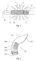
Fig. 1 is a scheme showing the operation principle of the device manufactured by the method and apparatus according to the invention; -
Fig. 2 is a schematic view of a first embodiment of a silencer device manufactured by the method and apparatus according to the presentinvention; -
Fig. 3 is a schematic view of an embodiment which does not form part of the invention; -
Fig. 4 is a perspective view of an intake conduit for internal combustion engines; -
Fig. 5A is a plan view of a half-mould; -
Fig. 5B is an enlarged view of a detail ofFig. 5A ; -
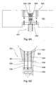
Fig. 6A is a cross-sectional view taken along line VI-VI offig. 5A ; -
Fig. 6B is an enlarged view of a detail ofFig. 6A with the needles in idle condition; -
Fig. 6C is an enlarged view of a detail ofFig. 6A with the needles pulled out; -
Fig. 7 is a diagram of an intake system for an internal combustion engine. - Referring to
Fig. 1 , the principle on which a silencer device manufactured by the method and apparatus according to the present invention is based is schematically shown. - Acoustic waves emitted by a loudspeaker AP in axial direction, from the left to the right in the Figure, as shown by arrow F, travel along a
conduit 11 having awall 13, aninlet mouth 15 and anoutlet mouth 17. - Advantageously, said
conduit 11 further has a set oforifices 19 alongwall 13 definingconduit 11 itself, said orifices putting the inside of the conduit in communication with the outside. - In the illustrated system, overall acoustic power Wtot emitted by loudspeaker AP is given by relation:

where: - Wout is the acoustic power at
outlet mouth 17 ofconduit 11; - Wrad is the acoustic power transmitted by
wall 13 ofconduit 11 in the direction shown by arrows C; - Wdis is the acoustic power thermally and mechanically dissipated through
orifices 19. - For a same amount of acoustic power being produced, an increase of acoustic power Wdis dissipated through
orifices 19 will result in a corresponding reduction of acoustic power Wout at the outlet mouth. - The present invention is based on the discovery that such a physical principle can be advantageously applied to produce silencer devices for conduits along which a fluid, in particular a gaseous fluid, flows, in order to reduce the noise produced by the pressure variations the fluid is subjected to, in particular the variations due to the fluid inflow into the conduit and to the shape of the conduit itself.
- The silencer device manufactured by the method and apparatus according to the present invention comprises a dissipating element, which has at least two and preferably at least four orifices and is formed or applied at least in correspondence of a portion of the wall defining the conduit, said orifices putting the inside of the conduit in communication with the outside.
- Said device will preferably be formed directly integrated into the conduit wall, which therefore will have orifices in at least a portion thereof, but it can also be made by applying, for instance in correspondence of a window formed on the conduit wall, a body having orifices.
- The silencer device thus obtained advantageously allows cutting down the noise propagating along the conduit.
- Said device can be applied in particular in the conduits of the intake system of internal combustion engines, for instance engines used in vehicles.
- Referring to
Fig. 2 , there is shown a first embodiment of a silencer device manufactured by the method and apparatus according to the invention, where ageneric conduit 211, defined by awall 213 and having aninlet mouth 215 and anoutlet mouth 217, includes saidsilencer device 221 consisting of anelement 223 with a plurality oforifices 219. which is directly formed onwall 213 ofconduit 211. - In the illustrated exemplary embodiment,
silencer device 221 is formed in correspondence of one side of a curved portion ofconduit 211, and it can be seen through the section made in the Figure on the opposite side. - In accordance with this first embodiment of the silencer device manufactured by the method and apparatus according to the invention, monolithic conduits of a material homogeneous with the integrated silencer device can be produced, and the device can extend over the whole or part of the surface of the wall defining the conduit.
- Referring now to
Fig. 3 , there is shown an embodiment which does not form part of the invention, where ageneric conduit 311, defined by awall 313 and having aninlet mouth 315 and anoutlet mouth 317, includes asilencer device 321 consisting of anelement 323 with a plurality oforifices 319, which is applied onwall 313 ofconduit 311, for instance by soldering or gluing, in correspondence of awindow 325 formed on the wall of said conduit. - In the illustrated exemplary embodiment, which does not form part of the present invention,
silencer device 321 is applied in correspondence of one side of a curved portion ofconduit 311, corresponding to the front side that can be seen in the Figure. - In accordance with this embodiment which does not form part of the invention, existing conduits can be equipped with the silencer device, which can be a separate body applied to the conduit wall or a hose inserted between two successive sections of the same conduit or of different conduits.
- Referring now to
Fig. 4 , there is shown ageneric intake conduit 411 for a turbocharged diesel cycle internal combustion engine for a motor vehicle, which conduit has been equipped with asilencer device 421 manufactured by the method and apparatus according to the invention. -
Conduit 411 is of the kind associated with the intake system in the initial portion conveying fresh air from the external environment towards the filter. -
Said conduit 411 is defined by awall 413 and has aninlet mouth 415 and anoutlet mouth 417.Conduit 411 has a winding shape and is equipped with at least one bellows 429 integrated intoconduit wall 413. - Advantageously,
wall 413 ofconduit 411 hasorifices 419, highlighted in the enlarged portion ofFig. 4 , which are distributed over aportion 423 ofwall 413. Said orifices are formed by piercingwall 413 and they have a diameter "d" of about 0.8 mm and a pitch "p" of about 4.0 mm. - In accordance with this embodiment,
conduit 411 can advantageously be made of plastics, preferably as an integral piece, andorifices 419 are formed inwall 413 either whileconduit 411 is being formed. - Reference is now made to
Figs. 5A to 6C in order to disclose a preferred embodiment of the method according to the invention. - The silencer device manufactured by the method and apparatus according to the invention is directly formed on the wall of a fluid conduit by piercing, in at least one conduit portion, at least two and preferably at least four circular micro-orifices with a diameter lower than 5.0 mm and preferably ranging from about 0.5 to 1.5 mm, and with a pitch of the order of some millimetres, e.g. ranging from 1 to 10 mm and preferably of about 4.0 mm.
- In a preferred embodiment of the invention, the conduit is made of a thermoplastic material, e.g. thermoplastic polyester (TEEE) or rigid-soft polyamide (PA) or polypropylene (GF) and thermoplastic rubber (PPGF + PP/EPDM).
- Advantageously, such materials enable dispensing with the use of non-recyclable materials, such as rubber, while reducing at the same time the weights.
- The manufacture of the conduit takes place by exploiting the blow-moulding technology, which, among its main advantages, enables manufacturing special products having a complex geometry and combining, in a single piece, characteristics of stiffness, resilience and capability of deformation with high dimensional precision and stability.
- According to the technique of blow-moulding plastics, a tube-shaped extruded blank, the so-called parison, is placed on one of the half-moulds of the mould of a blow-moulding machine.
- The parison is then clenched between the half-moulds and compressed air is blown into the clenched parison that expands until taking the shape of the mould cavity.
- In the whole, the blow-moulding process comprises therefore the steps of: placing the parison in the half-mould; closing the mould; blowing; removing the formed piece.
- According to the invention, at least one of half-
moulds 551 of a machine for blow-moulding plastics is equipped with a piercingassembly 553. - In an exemplary embodiment of the invention, said piercing
assembly 553 comprises asupport 555 slidable in aseat 556 formed in the half-mould body, thanks to acontrol unit 557 for instance of pneumatic type. Such asupport 555 has associated therewithneedles 559 that, when sliding, jointly withsupport 555, in correspondingseats 561 formed in the body of half-mould 551, penetrate during blowing into the body ofparison 563, a portion of which can be seen, and enable forming corresponding orifices on the wall of the conduit obtained at the end of the blowing step. - In the illustrated example, piercing
assembly 553 has nineneedles 559 in order to pierce an equal number of holes intoparison 563, which holes have axes substantially perpendicular to the wall of the conduit obtained by moulding the parison. - According to the invention, piercing assemblies with a different number of needles and/or multiple piercing assemblies in one or both half-moulds, and even with different penetration directions, can be envisaged.
- Always according to the invention, the piercing assembly (assemblies) are pneumatically controlled while the parison blowing takes place.
Claims (12)
- A method for manufacturing a silencer device in a single piece with a conduit where a fluid can flow, wherein said conduit is provided with a plurality of orifices that put the inside of the conduit in communication with the outside by forming said orifices on said conduit during a blow-moulding process;
said method being characterised in that said blow-moulding process comprises the following steps:- providing a blow-moulding machine comprising a mould with at least two half-moulds;- providing a parison made of plastic material and intended to be blown- placing said parison in one of said half-moulds;- clenching said parison between said half moulds by closing said mould;- blowing compressed air into the parison contained in said mould;- forming said orifices on said conduit by:moving a slidable support (555) by means of a control unit (557); said slidable support (555) belonging to a piercing assembly (553) provided in at least one of said half moulds, andmaking needles (559), which are associated with said slidable support (555), to slide jointly therewith into corresponding seats (561) formed in the body of at least one of said moulds, and to penetrate into the body of the parison (563) in order to form said orifices during said blowing step; and- removing the formed conduit form the mould. - The method of claim 1, wherein said orifices are formed by moving a plurality of said piercing assemblies (553).
- The method of claim 2, wherein said piercing assemblies (553) are provided in the same half mould.
- The method of claim 2, wherein said piercing assemblies (553) are provided in different half moulds.
- The method of any of claims 2 to 4, wherein said piercing assemblies (553) act in different penetration directions.
- The method of any of the preceding claims, wherein said slidable support (555) is moved by a pneumatic control unit (557).
- Apparatus for manufacturing a silencer device in a single piece with a conduit where a fluid can flow, wherein said conduit is provided with a plurality of orifices that put the inside of the conduit in communication with the outside;
said apparatus being characterised in that comprises:- a blow-moulding machine having a mould comprising at least two half-moulds and intended to clench a parison therebetween; said parison being made of plastic material and intended to be blown into said mould by means of compressed air; one of said half moulds being suitable for receiving said parison;- at least one piercing assembly (553) provided in at least one of said half moulds and including a slidable support (555) having associated needles (559); and- a control unit (557) arranged for sliding said slidable support (555) jointly with said needles (559) into corresponding seats (561) formed in the body of at least one of said half moulds, so as to make said needles (559) to penetrate the body of said parison in order to form said orifices when said parison is blown. - The apparatus of claim 7, wherein it comprises a plurality of piercing assemblies (553).
- The apparatus of claim 8, wherein said piercing assemblies (553) are provided in the same half mould.
- The apparatus of claim 8, wherein said piercing assemblies (553) are provided in different half moulds.
- The apparatus of any of claims 8 to 10, wherein said piercing assemblies (553) are arranged to act in different penetration directions.
- The apparatus of any of the claims 7 to 11; wherein said control unit (557) is of the pneumatic kind.
Applications Claiming Priority (1)
| Application Number | Priority Date | Filing Date | Title |
|---|---|---|---|
| IT000529A ITTO20070529A1 (en) | 2007-07-17 | 2007-07-17 | SILENCER DEVICE FOR A CONDUCT TO BE TRAVELED BY A FLUID AND ITS METHOD OF REALIZATION. |
Publications (2)
| Publication Number | Publication Date |
|---|---|
| EP2017440A1 EP2017440A1 (en) | 2009-01-21 |
| EP2017440B1 true EP2017440B1 (en) | 2010-02-24 |
Family
ID=39926451
Family Applications (1)
| Application Number | Title | Priority Date | Filing Date |
|---|---|---|---|
| EP08159563A Not-in-force EP2017440B1 (en) | 2007-07-17 | 2008-07-02 | Method for manufacturing a silencer device and an apparatus for manufacturing said device |
Country Status (5)
| Country | Link |
|---|---|
| EP (1) | EP2017440B1 (en) |
| AT (1) | ATE458901T1 (en) |
| DE (1) | DE602008000694D1 (en) |
| ES (1) | ES2342133T3 (en) |
| IT (1) | ITTO20070529A1 (en) |
Cited By (1)
| Publication number | Priority date | Publication date | Assignee | Title |
|---|---|---|---|---|
| US10047650B2 (en) | 2014-03-31 | 2018-08-14 | Faurencia Emissions Technologies USA, LLC | Vehicle exhaust system with resistive patch |
Families Citing this family (5)
| Publication number | Priority date | Publication date | Assignee | Title |
|---|---|---|---|---|
| IT1400167B1 (en) * | 2010-05-21 | 2013-05-17 | Fiat Group Automobiles Spa | SILENT DUCT FOR FLUID FLOWS AND METHOD FOR ITS ACHIEVEMENT. |
| DE102012014620A1 (en) * | 2012-07-24 | 2014-01-30 | Faurecia Emissions Control Technologies, Germany Gmbh | Exhaust-carrying component of an exhaust system |
| CN104995378B (en) | 2013-02-12 | 2019-06-25 | 佛吉亚排放控制技术美国有限公司 | Vehicle exhaust system with resonance damping |
| GB2546792A (en) * | 2016-01-29 | 2017-08-02 | Dyson Technology Ltd | A silencer |
| CN113847118B (en) * | 2021-09-10 | 2022-10-18 | 浙江吉利控股集团有限公司 | System and method for actively sounding exhaust silencer assembly |
Family Cites Families (7)
| Publication number | Priority date | Publication date | Assignee | Title |
|---|---|---|---|---|
| DE19629368A1 (en) * | 1996-07-20 | 1998-01-22 | Gillet Heinrich Gmbh | Resonance damper for motor vehicle exhaust pipe |
| JPH11280479A (en) * | 1998-03-27 | 1999-10-12 | Calsonic Corp | Intercooler |
| DE19903165A1 (en) * | 1999-01-27 | 2000-08-03 | Mann & Hummel Filter | Suction device with a line section having openings |
| GB2364352A (en) * | 2000-07-03 | 2002-01-23 | Draftex Ind Ltd | Noise reduction in air conduits; making perforated conduits |
| FR2814778B1 (en) * | 2000-09-29 | 2003-01-10 | Peugeot Citroen Automobiles Sa | CONDUIT FOR THE TRANSPORT OF GASEOUS FLUID AND AIR INTAKE DEVICE FOR AN INTERNAL COMBUSTION ENGINE COMPRISING SUCH A CONDUIT |
| SE522546C2 (en) * | 2001-02-21 | 2004-02-17 | Volvo Lastvagnar Ab | Device for attenuating resonance in a pipeline |
| FR2867234B1 (en) * | 2004-03-02 | 2007-11-16 | Peugeot Citroen Automobiles Sa | DEVICE FOR THE ACOUSTICAL ATTENUATION OF A GAS CIRCULATION DUCT OF A THERMAL ENGINE |
-
2007
- 2007-07-17 IT IT000529A patent/ITTO20070529A1/en unknown
-
2008
- 2008-07-02 AT AT08159563T patent/ATE458901T1/en not_active IP Right Cessation
- 2008-07-02 EP EP08159563A patent/EP2017440B1/en not_active Not-in-force
- 2008-07-02 DE DE602008000694T patent/DE602008000694D1/en active Active
- 2008-07-02 ES ES08159563T patent/ES2342133T3/en active Active
Cited By (1)
| Publication number | Priority date | Publication date | Assignee | Title |
|---|---|---|---|---|
| US10047650B2 (en) | 2014-03-31 | 2018-08-14 | Faurencia Emissions Technologies USA, LLC | Vehicle exhaust system with resistive patch |
Also Published As
| Publication number | Publication date |
|---|---|
| EP2017440A1 (en) | 2009-01-21 |
| ATE458901T1 (en) | 2010-03-15 |
| ITTO20070529A1 (en) | 2009-01-18 |
| DE602008000694D1 (en) | 2010-04-08 |
| ES2342133T3 (en) | 2010-07-01 |
Similar Documents
| Publication | Publication Date | Title |
|---|---|---|
| EP2017440A1 (en) | Silencer device for a fluid conduit and method for its production | |
| US8323556B2 (en) | Manufacture of an acoustic silencer | |
| US6302228B1 (en) | Device and method for removing heat energy from a compartment | |
| EP0701083B1 (en) | Hollow plastic product having a sound attenuator and method for manufacturing the same | |
| KR960003690B1 (en) | Multi-layer plastic pipe and its manufacturing process | |
| US5529743A (en) | Methods for the manufacture of clean air ducts | |
| US9228542B2 (en) | Swirl vane air duct cuff assembly and method of manufacture | |
| US5821473A (en) | Silencer and a method for forming and attaching a silencer to a blower pipe | |
| EP1070843A1 (en) | Suction duct | |
| JPH1077920A (en) | Intake pipe of internal combustion engine | |
| JPH0839657A (en) | Hollow body having a support frame located inwardly and method for manufacturing the hollow body | |
| US20070068589A1 (en) | Intake duct | |
| US20100132649A1 (en) | Method and device for producing a pipe | |
| US6176213B1 (en) | Admission system for an internal combustion engine | |
| JP2008231956A (en) | Sound absorbing structure | |
| CN110043402A (en) | Whole inlet manifold | |
| CN107314186A (en) | Breather line with muffler | |
| CN101275522A (en) | Flexible seal and molded rigid chamber | |
| KR100456569B1 (en) | Intercooler pipe for automobile | |
| EP1375117A2 (en) | High stiffness plastic wall for molded plastic products | |
| JP5828807B2 (en) | Intake manifold | |
| EP4234065A1 (en) | Housing for a filter element and filter system comprising a housing | |
| JP4716511B2 (en) | Engine parts mounting device | |
| JPH04132870A (en) | Manufacture of intake pipe for engine | |
| CN110043401A (en) | Whole inlet manifold |
Legal Events
| Date | Code | Title | Description |
|---|---|---|---|
| PUAI | Public reference made under article 153(3) epc to a published international application that has entered the european phase |
Free format text: ORIGINAL CODE: 0009012 |
|
| AK | Designated contracting states |
Kind code of ref document: A1 Designated state(s): AT BE BG CH CY CZ DE DK EE ES FI FR GB GR HR HU IE IS IT LI LT LU LV MC MT NL NO PL PT RO SE SI SK TR |
|
| AX | Request for extension of the european patent |
Extension state: AL BA MK RS |
|
| 17P | Request for examination filed |
Effective date: 20090623 |
|
| GRAP | Despatch of communication of intention to grant a patent |
Free format text: ORIGINAL CODE: EPIDOSNIGR1 |
|
| AKX | Designation fees paid |
Designated state(s): AT BE BG CH CY CZ DE DK EE ES FI FR GB GR HR HU IE IS IT LI LT LU LV MC MT NL NO PL PT RO SE SI SK TR |
|
| RTI1 | Title (correction) |
Free format text: METHOD FOR MANUFACTURING A SILENCER DEVICE AND AN APPARATUS FOR MANUFACTURING SAID DEVICE |
|
| GRAS | Grant fee paid |
Free format text: ORIGINAL CODE: EPIDOSNIGR3 |
|
| GRAA | (expected) grant |
Free format text: ORIGINAL CODE: 0009210 |
|
| AK | Designated contracting states |
Kind code of ref document: B1 Designated state(s): AT BE BG CH CY CZ DE DK EE ES FI FR GB GR HR HU IE IS IT LI LT LU LV MC MT NL NO PL PT RO SE SI SK TR |
|
| REG | Reference to a national code |
Ref country code: GB Ref legal event code: FG4D |
|
| REG | Reference to a national code |
Ref country code: CH Ref legal event code: EP |
|
| REG | Reference to a national code |
Ref country code: IE Ref legal event code: FG4D |
|
| REF | Corresponds to: |
Ref document number: 602008000694 Country of ref document: DE Date of ref document: 20100408 Kind code of ref document: P |
|
| REG | Reference to a national code |
Ref country code: NL Ref legal event code: VDEP Effective date: 20100224 |
|
| REG | Reference to a national code |
Ref country code: ES Ref legal event code: FG2A Ref document number: 2342133 Country of ref document: ES Kind code of ref document: T3 |
|
| LTIE | Lt: invalidation of european patent or patent extension |
Effective date: 20100224 |
|
| PG25 | Lapsed in a contracting state [announced via postgrant information from national office to epo] |
Ref country code: IS Free format text: LAPSE BECAUSE OF FAILURE TO SUBMIT A TRANSLATION OF THE DESCRIPTION OR TO PAY THE FEE WITHIN THE PRESCRIBED TIME-LIMIT Effective date: 20100624 Ref country code: HR Free format text: LAPSE BECAUSE OF FAILURE TO SUBMIT A TRANSLATION OF THE DESCRIPTION OR TO PAY THE FEE WITHIN THE PRESCRIBED TIME-LIMIT Effective date: 20100224 Ref country code: NO Free format text: LAPSE BECAUSE OF FAILURE TO SUBMIT A TRANSLATION OF THE DESCRIPTION OR TO PAY THE FEE WITHIN THE PRESCRIBED TIME-LIMIT Effective date: 20100524 Ref country code: LT Free format text: LAPSE BECAUSE OF FAILURE TO SUBMIT A TRANSLATION OF THE DESCRIPTION OR TO PAY THE FEE WITHIN THE PRESCRIBED TIME-LIMIT Effective date: 20100224 |
|
| PG25 | Lapsed in a contracting state [announced via postgrant information from national office to epo] |
Ref country code: LV Free format text: LAPSE BECAUSE OF FAILURE TO SUBMIT A TRANSLATION OF THE DESCRIPTION OR TO PAY THE FEE WITHIN THE PRESCRIBED TIME-LIMIT Effective date: 20100224 Ref country code: PL Free format text: LAPSE BECAUSE OF FAILURE TO SUBMIT A TRANSLATION OF THE DESCRIPTION OR TO PAY THE FEE WITHIN THE PRESCRIBED TIME-LIMIT Effective date: 20100224 Ref country code: FI Free format text: LAPSE BECAUSE OF FAILURE TO SUBMIT A TRANSLATION OF THE DESCRIPTION OR TO PAY THE FEE WITHIN THE PRESCRIBED TIME-LIMIT Effective date: 20100224 Ref country code: SI Free format text: LAPSE BECAUSE OF FAILURE TO SUBMIT A TRANSLATION OF THE DESCRIPTION OR TO PAY THE FEE WITHIN THE PRESCRIBED TIME-LIMIT Effective date: 20100224 Ref country code: AT Free format text: LAPSE BECAUSE OF FAILURE TO SUBMIT A TRANSLATION OF THE DESCRIPTION OR TO PAY THE FEE WITHIN THE PRESCRIBED TIME-LIMIT Effective date: 20100224 |
|
| PG25 | Lapsed in a contracting state [announced via postgrant information from national office to epo] |
Ref country code: NL Free format text: LAPSE BECAUSE OF FAILURE TO SUBMIT A TRANSLATION OF THE DESCRIPTION OR TO PAY THE FEE WITHIN THE PRESCRIBED TIME-LIMIT Effective date: 20100224 Ref country code: CY Free format text: LAPSE BECAUSE OF FAILURE TO SUBMIT A TRANSLATION OF THE DESCRIPTION OR TO PAY THE FEE WITHIN THE PRESCRIBED TIME-LIMIT Effective date: 20100224 Ref country code: SE Free format text: LAPSE BECAUSE OF FAILURE TO SUBMIT A TRANSLATION OF THE DESCRIPTION OR TO PAY THE FEE WITHIN THE PRESCRIBED TIME-LIMIT Effective date: 20100224 Ref country code: RO Free format text: LAPSE BECAUSE OF FAILURE TO SUBMIT A TRANSLATION OF THE DESCRIPTION OR TO PAY THE FEE WITHIN THE PRESCRIBED TIME-LIMIT Effective date: 20100224 Ref country code: BE Free format text: LAPSE BECAUSE OF FAILURE TO SUBMIT A TRANSLATION OF THE DESCRIPTION OR TO PAY THE FEE WITHIN THE PRESCRIBED TIME-LIMIT Effective date: 20100224 Ref country code: EE Free format text: LAPSE BECAUSE OF FAILURE TO SUBMIT A TRANSLATION OF THE DESCRIPTION OR TO PAY THE FEE WITHIN THE PRESCRIBED TIME-LIMIT Effective date: 20100224 Ref country code: GR Free format text: LAPSE BECAUSE OF FAILURE TO SUBMIT A TRANSLATION OF THE DESCRIPTION OR TO PAY THE FEE WITHIN THE PRESCRIBED TIME-LIMIT Effective date: 20100525 |
|
| PG25 | Lapsed in a contracting state [announced via postgrant information from national office to epo] |
Ref country code: CZ Free format text: LAPSE BECAUSE OF FAILURE TO SUBMIT A TRANSLATION OF THE DESCRIPTION OR TO PAY THE FEE WITHIN THE PRESCRIBED TIME-LIMIT Effective date: 20100224 Ref country code: BG Free format text: LAPSE BECAUSE OF FAILURE TO SUBMIT A TRANSLATION OF THE DESCRIPTION OR TO PAY THE FEE WITHIN THE PRESCRIBED TIME-LIMIT Effective date: 20100524 Ref country code: SK Free format text: LAPSE BECAUSE OF FAILURE TO SUBMIT A TRANSLATION OF THE DESCRIPTION OR TO PAY THE FEE WITHIN THE PRESCRIBED TIME-LIMIT Effective date: 20100224 |
|
| PLBE | No opposition filed within time limit |
Free format text: ORIGINAL CODE: 0009261 |
|
| STAA | Information on the status of an ep patent application or granted ep patent |
Free format text: STATUS: NO OPPOSITION FILED WITHIN TIME LIMIT |
|
| PG25 | Lapsed in a contracting state [announced via postgrant information from national office to epo] |
Ref country code: DK Free format text: LAPSE BECAUSE OF FAILURE TO SUBMIT A TRANSLATION OF THE DESCRIPTION OR TO PAY THE FEE WITHIN THE PRESCRIBED TIME-LIMIT Effective date: 20100224 |
|
| 26N | No opposition filed |
Effective date: 20101125 |
|
| PG25 | Lapsed in a contracting state [announced via postgrant information from national office to epo] |
Ref country code: MC Free format text: LAPSE BECAUSE OF NON-PAYMENT OF DUE FEES Effective date: 20100731 |
|
| PG25 | Lapsed in a contracting state [announced via postgrant information from national office to epo] |
Ref country code: IE Free format text: LAPSE BECAUSE OF NON-PAYMENT OF DUE FEES Effective date: 20100702 |
|
| PG25 | Lapsed in a contracting state [announced via postgrant information from national office to epo] |
Ref country code: MT Free format text: LAPSE BECAUSE OF FAILURE TO SUBMIT A TRANSLATION OF THE DESCRIPTION OR TO PAY THE FEE WITHIN THE PRESCRIBED TIME-LIMIT Effective date: 20100224 |
|
| PG25 | Lapsed in a contracting state [announced via postgrant information from national office to epo] |
Ref country code: HU Free format text: LAPSE BECAUSE OF FAILURE TO SUBMIT A TRANSLATION OF THE DESCRIPTION OR TO PAY THE FEE WITHIN THE PRESCRIBED TIME-LIMIT Effective date: 20100825 Ref country code: PT Free format text: LAPSE BECAUSE OF FAILURE TO SUBMIT A TRANSLATION OF THE DESCRIPTION OR TO PAY THE FEE WITHIN THE PRESCRIBED TIME-LIMIT Effective date: 20100724 Ref country code: LU Free format text: LAPSE BECAUSE OF NON-PAYMENT OF DUE FEES Effective date: 20100702 |
|
| PG25 | Lapsed in a contracting state [announced via postgrant information from national office to epo] |
Ref country code: TR Free format text: LAPSE BECAUSE OF FAILURE TO SUBMIT A TRANSLATION OF THE DESCRIPTION OR TO PAY THE FEE WITHIN THE PRESCRIBED TIME-LIMIT Effective date: 20100224 |
|
| REG | Reference to a national code |
Ref country code: CH Ref legal event code: PL |
|
| PG25 | Lapsed in a contracting state [announced via postgrant information from national office to epo] |
Ref country code: CH Free format text: LAPSE BECAUSE OF NON-PAYMENT OF DUE FEES Effective date: 20120731 Ref country code: LI Free format text: LAPSE BECAUSE OF NON-PAYMENT OF DUE FEES Effective date: 20120731 |
|
| REG | Reference to a national code |
Ref country code: FR Ref legal event code: PLFP Year of fee payment: 8 |
|
| REG | Reference to a national code |
Ref country code: FR Ref legal event code: PLFP Year of fee payment: 9 |
|
| REG | Reference to a national code |
Ref country code: FR Ref legal event code: PLFP Year of fee payment: 10 |
|
| REG | Reference to a national code |
Ref country code: FR Ref legal event code: PLFP Year of fee payment: 11 |
|
| PGFP | Annual fee paid to national office [announced via postgrant information from national office to epo] |
Ref country code: DE Payment date: 20180926 Year of fee payment: 11 Ref country code: ES Payment date: 20180801 Year of fee payment: 11 Ref country code: IT Payment date: 20180723 Year of fee payment: 11 Ref country code: FR Payment date: 20180719 Year of fee payment: 11 |
|
| PGFP | Annual fee paid to national office [announced via postgrant information from national office to epo] |
Ref country code: GB Payment date: 20180731 Year of fee payment: 11 |
|
| REG | Reference to a national code |
Ref country code: DE Ref legal event code: R119 Ref document number: 602008000694 Country of ref document: DE |
|
| GBPC | Gb: european patent ceased through non-payment of renewal fee |
Effective date: 20190702 |
|
| PG25 | Lapsed in a contracting state [announced via postgrant information from national office to epo] |
Ref country code: DE Free format text: LAPSE BECAUSE OF NON-PAYMENT OF DUE FEES Effective date: 20200201 Ref country code: GB Free format text: LAPSE BECAUSE OF NON-PAYMENT OF DUE FEES Effective date: 20190702 |
|
| PG25 | Lapsed in a contracting state [announced via postgrant information from national office to epo] |
Ref country code: FR Free format text: LAPSE BECAUSE OF NON-PAYMENT OF DUE FEES Effective date: 20190731 |
|
| PG25 | Lapsed in a contracting state [announced via postgrant information from national office to epo] |
Ref country code: IT Free format text: LAPSE BECAUSE OF NON-PAYMENT OF DUE FEES Effective date: 20190702 |
|
| REG | Reference to a national code |
Ref country code: ES Ref legal event code: FD2A Effective date: 20201126 |
|
| PG25 | Lapsed in a contracting state [announced via postgrant information from national office to epo] |
Ref country code: ES Free format text: LAPSE BECAUSE OF NON-PAYMENT OF DUE FEES Effective date: 20190703 |