EP2017434B1 - Variable-shape variable-stagger inlet guide vane flap - Google Patents
Variable-shape variable-stagger inlet guide vane flap Download PDFInfo
- Publication number
- EP2017434B1 EP2017434B1 EP08252106.3A EP08252106A EP2017434B1 EP 2017434 B1 EP2017434 B1 EP 2017434B1 EP 08252106 A EP08252106 A EP 08252106A EP 2017434 B1 EP2017434 B1 EP 2017434B1
- Authority
- EP
- European Patent Office
- Prior art keywords
- section
- flexible portion
- guide vane
- inlet guide
- variable
- Prior art date
- Legal status (The legal status is an assumption and is not a legal conclusion. Google has not performed a legal analysis and makes no representation as to the accuracy of the status listed.)
- Active
Links
Images




Classifications
-
- F—MECHANICAL ENGINEERING; LIGHTING; HEATING; WEAPONS; BLASTING
- F01—MACHINES OR ENGINES IN GENERAL; ENGINE PLANTS IN GENERAL; STEAM ENGINES
- F01D—NON-POSITIVE DISPLACEMENT MACHINES OR ENGINES, e.g. STEAM TURBINES
- F01D5/00—Blades; Blade-carrying members; Heating, heat-insulating, cooling or antivibration means on the blades or the members
- F01D5/12—Blades
- F01D5/14—Form or construction
- F01D5/141—Shape, i.e. outer, aerodynamic form
- F01D5/146—Shape, i.e. outer, aerodynamic form of blades with tandem configuration, split blades or slotted blades
-
- F—MECHANICAL ENGINEERING; LIGHTING; HEATING; WEAPONS; BLASTING
- F01—MACHINES OR ENGINES IN GENERAL; ENGINE PLANTS IN GENERAL; STEAM ENGINES
- F01D—NON-POSITIVE DISPLACEMENT MACHINES OR ENGINES, e.g. STEAM TURBINES
- F01D17/00—Regulating or controlling by varying flow
- F01D17/10—Final actuators
- F01D17/12—Final actuators arranged in stator parts
- F01D17/14—Final actuators arranged in stator parts varying effective cross-sectional area of nozzles or guide conduits
- F01D17/16—Final actuators arranged in stator parts varying effective cross-sectional area of nozzles or guide conduits by means of nozzle vanes
- F01D17/162—Final actuators arranged in stator parts varying effective cross-sectional area of nozzles or guide conduits by means of nozzle vanes for axial flow, i.e. the vanes turning around axes which are essentially perpendicular to the rotor centre line
-
- F—MECHANICAL ENGINEERING; LIGHTING; HEATING; WEAPONS; BLASTING
- F01—MACHINES OR ENGINES IN GENERAL; ENGINE PLANTS IN GENERAL; STEAM ENGINES
- F01D—NON-POSITIVE DISPLACEMENT MACHINES OR ENGINES, e.g. STEAM TURBINES
- F01D5/00—Blades; Blade-carrying members; Heating, heat-insulating, cooling or antivibration means on the blades or the members
- F01D5/12—Blades
- F01D5/14—Form or construction
- F01D5/148—Blades with variable camber, e.g. by ejection of fluid
-
- F—MECHANICAL ENGINEERING; LIGHTING; HEATING; WEAPONS; BLASTING
- F04—POSITIVE - DISPLACEMENT MACHINES FOR LIQUIDS; PUMPS FOR LIQUIDS OR ELASTIC FLUIDS
- F04D—NON-POSITIVE-DISPLACEMENT PUMPS
- F04D29/00—Details, component parts, or accessories
- F04D29/40—Casings; Connections of working fluid
- F04D29/52—Casings; Connections of working fluid for axial pumps
- F04D29/54—Fluid-guiding means, e.g. diffusers
- F04D29/56—Fluid-guiding means, e.g. diffusers adjustable
- F04D29/563—Fluid-guiding means, e.g. diffusers adjustable specially adapted for elastic fluid pumps
-
- F—MECHANICAL ENGINEERING; LIGHTING; HEATING; WEAPONS; BLASTING
- F05—INDEXING SCHEMES RELATING TO ENGINES OR PUMPS IN VARIOUS SUBCLASSES OF CLASSES F01-F04
- F05B—INDEXING SCHEME RELATING TO WIND, SPRING, WEIGHT, INERTIA OR LIKE MOTORS, TO MACHINES OR ENGINES FOR LIQUIDS COVERED BY SUBCLASSES F03B, F03D AND F03G
- F05B2240/00—Components
- F05B2240/20—Rotors
- F05B2240/30—Characteristics of rotor blades, i.e. of any element transforming dynamic fluid energy to or from rotational energy and being attached to a rotor
- F05B2240/31—Characteristics of rotor blades, i.e. of any element transforming dynamic fluid energy to or from rotational energy and being attached to a rotor of changeable form or shape
- F05B2240/311—Characteristics of rotor blades, i.e. of any element transforming dynamic fluid energy to or from rotational energy and being attached to a rotor of changeable form or shape flexible or elastic
-
- F—MECHANICAL ENGINEERING; LIGHTING; HEATING; WEAPONS; BLASTING
- F05—INDEXING SCHEMES RELATING TO ENGINES OR PUMPS IN VARIOUS SUBCLASSES OF CLASSES F01-F04
- F05D—INDEXING SCHEME FOR ASPECTS RELATING TO NON-POSITIVE-DISPLACEMENT MACHINES OR ENGINES, GAS-TURBINES OR JET-PROPULSION PLANTS
- F05D2240/00—Components
- F05D2240/10—Stators
- F05D2240/12—Fluid guiding means, e.g. vanes
-
- Y—GENERAL TAGGING OF NEW TECHNOLOGICAL DEVELOPMENTS; GENERAL TAGGING OF CROSS-SECTIONAL TECHNOLOGIES SPANNING OVER SEVERAL SECTIONS OF THE IPC; TECHNICAL SUBJECTS COVERED BY FORMER USPC CROSS-REFERENCE ART COLLECTIONS [XRACs] AND DIGESTS
- Y02—TECHNOLOGIES OR APPLICATIONS FOR MITIGATION OR ADAPTATION AGAINST CLIMATE CHANGE
- Y02T—CLIMATE CHANGE MITIGATION TECHNOLOGIES RELATED TO TRANSPORTATION
- Y02T50/00—Aeronautics or air transport
- Y02T50/60—Efficient propulsion technologies, e.g. for aircraft
Definitions
- the present invention relates to a gas turbine engine.
- Low bypass ratio gas turbine engines include fan sections that are often configured with variable-stagger inlet guide vanes (IGVs).
- IGVs are typically disposed as a single stage of articulated airfoils (about a radial axis) located forward of the fan rotor blades of the fan section.
- Conventional IGVs provide a relatively flat fan inlet relative Mach number and fan exit (Pt) profile for increased design point performance, increased off-design partial-speed operability and flutter margin.
- the IGVs typically have 20 degrees of twist from root to tip. At the design point stagger angle setting, this twist distribution provides an IGV exit flow with coswirl at tip and counterswirl at root relative to the fan rotor rotation direction. When this twist distribution is staggered to ⁇ 50 degrees closed at partial-speed conditions, there may be significant spanwise flow redistribution such that the tip region of the annulus may have a relatively low axial velocity (Cx) and an associated undesirable high positive incidence at the fan rotor tip section.
- Cx axial velocity
- the present invention provides an inlet guide vane in accordance with claim 1.
- variable shape inlet guide vane (IGV) system provides a variable-shape IGV flap having a flexible portion with a desired spanwise distribution of Cx, alpha, and beta at a fan rotor inlet.
- the flexible portion of the flap is constructed from compliant material such as silicon rubber which may also incorporate internal stiffening fibers or filaments.
- An actuation system rotates a root section of the IGV flap through a stagger angle range to provide a significant closed position at partial-speed condition in comparison to the tip section to flow towards the tip.
- the shape of the IGV flap is twisted rather symmetrically during actuation from max open to max closed.
- the present disclosure therefore provides an IGV flap with increased partial-speed operability and flutter margin, thus avoiding fan rotor mistuning at particular operational conditions.
- Figure 1 schematically illustrates a gas turbine engine 10 which generally includes a fan section 12, a compressor section 14, a combustor section 16, a turbine section 18, and a nozzle section 20 along a longitudinal axis X.
- the gas turbine engine 10 of the disclosed embodiment is a low bypass military-type gas turbine engine having a 3-stage fan, a 6-stage compressor, an annular combustor, a single stage high-pressure turbine, and a 2-stage low pressure turbine, however, various gas turbine engines will benefit from the present invention.
- An outer engine structure 22 and an inner engine structure 24 at least partially define an annular secondary fan bypass flow path 26. It should be understood that various structure within the engine may be defined as the outer engine structure 22 and the inner engine structure 24 to define the fan bypass flow path 26 downstream of a fan rotor.
- a fan rotor assembly 28 upstream of the compressor section 14 includes a multiple of fan rotor blades 30 circumferentially disposed around a disk 32, each fan rotor blade 30 includes a root 34 and an airfoil 36.
- the airfoils 36 extend radially outward such that the outer edge of each airfoil 36 may be referred to as the blade tip 44.
- variable shape inlet guide vane (IGV) system 46 Upstream of the fan rotor blades 30 is a variable shape inlet guide vane (IGV) system 46 (also illustrated in Figure 3 ). It should be understood that the IGV system 46 is located forward of a first stage of the fan section 12.
- the IGV system 46 includes a multiple of variable IGV flaps 48 circumferentially mounted between the outer engine structure 22 and the inner engine structure 24.
- each variable-shape IGV flap 48 includes a support strut 50 which extends between an inner support 52 and an outer support 55.
- the outer support 55 is attachable to the outer engine structure 22 and the inner support 52 is attachable to the inner engine structure 24 ( Figure 2 ) to provide support within the inlet of the engine 10.
- Each support strut 50 is at least partially surrounded by an airfoil 54 which defines a leading section 56 with a leading edge 58 generally forward of the strut 50 and a trailing section 60 with a trailing edge 62 generally aft of the support strut 50.
- the airfoil 54 includes a flexible portion 64 which is movable relative a fixed section 66.
- the flexible portion 64 forms at least part of the trailing section 60. In one disclosed embodiment, the flexible portion 64 spans the entire trailing edge 62.
- the flexible portion 64 may be constructed from compliant material such as silicon rubber which may also incorporate internal stiffening fibers or filaments. It should be understood that various flexible or rigid, as the movable portion may alternatively be rigid, structures may be utilized with the present application.
- An actuator system 68 includes an actuator such as an outer diameter unison ring (illustrated schematically at R) which rotates an actuator arm 70 and an actuator rod 72 which passes through the airfoil 54, the inner support 52 and the outer support 55.
- the actuator rod 72 is supported mid-span by a mid-span support 50S which extends from the support strut 50.
- An inner segment of the actuator rod is supported at an inner diameter pivot 76 which also supports an inner diameter rotating arm 78.
- the actuator rod 70 rotates the inner diameter rotating arm 78 which is attached to the flexible portion 64.
- the flexible portion 64 in one disclosed embodiment being triangular in shape with an inner diameter segment axially spanning the inner diameter rotating arm 78.
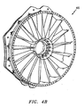
- the actuator rod 72 carries actuator torque to the inner diameter rotating arm 78 to resiliently flex the flexible portion 64 between a first position ( Figure 4A ) and a second position ( Figure 4B ).
- the flexible portion 64 may be located at essentially an infinite number of positions between the first position ( Figure 4A ) and the second position ( Figure 4B ) such that the airfoil 54 is essentially varied to more closely match engine operational profiles at various speeds to minimize fan rotor mistuning.
- the flexible portion 64 of each variable-shape IGV flap 48 reverses the twist rather symmetrically during actuation from the first position ( Figure 4A ) to the second position ( Figure 4B ).
- an embodiment of the invention includes a flexible portion 64' which spans a rectilinear portion of the trailing edge 62 of a trailing section 86.
- An actuator system 80 includes a dual actuator such as a primary outer diameter unison ring (illustrated schematically at 88) and a secondary outer diameter unison ring (illustrated schematically at 90).
- the primary outer diameter unison ring 88 rotates a primary actuator arm 92 mounted to the trailing section 86 of the airfoil 54'. That is, the entire trailing section 86 of the airfoil 54' is pitched relative the fixed leading section 56' in response to rotation of the primary actuator rod 94 about a flap axis F.
- the secondary outer diameter unison ring 90 rotates a secondary actuator arm 96 mounted to a secondary actuator rod 98 rotationally mounted through the primary actuator rod 94.
- the secondary actuator rod 98 is mounted to a secondary rotating arm 100 attached to the flexible portion 64'.
- the secondary actuator rod 98 rotates the inner diameter rotating arm 100 such that the flexible portion 64' is flexed relative the trailing section 86 of the airfoil 54' between a first position and a second position ( Figure 5B ).
- each variable-shape IGV flap 48' may be varied by the position of the trailing section 86 of the airfoil 54' relative the leading section 56' and the position of the flexible portion 64' relative the trailing section 86 such that there is a continuous spanwise alpha profile at the IGV exit.
Landscapes
- Engineering & Computer Science (AREA)
- Mechanical Engineering (AREA)
- General Engineering & Computer Science (AREA)
- Physics & Mathematics (AREA)
- Fluid Mechanics (AREA)
- Structures Of Non-Positive Displacement Pumps (AREA)
Description
- The present invention relates to a gas turbine engine.
- Low bypass ratio gas turbine engines include fan sections that are often configured with variable-stagger inlet guide vanes (IGVs). Conventional IGVs are typically disposed as a single stage of articulated airfoils (about a radial axis) located forward of the fan rotor blades of the fan section. Conventional IGVs provide a relatively flat fan inlet relative Mach number and fan exit (Pt) profile for increased design point performance, increased off-design partial-speed operability and flutter margin.
- The IGVs typically have 20 degrees of twist from root to tip. At the design point stagger angle setting, this twist distribution provides an IGV exit flow with coswirl at tip and counterswirl at root relative to the fan rotor rotation direction. When this twist distribution is staggered to ~50 degrees closed at partial-speed conditions, there may be significant spanwise flow redistribution such that the tip region of the annulus may have a relatively low axial velocity (Cx) and an associated undesirable high positive incidence at the fan rotor tip section.
- The features of the preamble to claim 1 are disclosed in
DE 961742 . A deformable flow deflector blade is disclosed inGB 2019793 - The present invention provides an inlet guide vane in accordance with claim 1.
- An embodiment of the variable shape inlet guide vane (IGV) system disclosed herein provides a variable-shape IGV flap having a flexible portion with a desired spanwise distribution of Cx, alpha, and beta at a fan rotor inlet. The flexible portion of the flap is constructed from compliant material such as silicon rubber which may also incorporate internal stiffening fibers or filaments. An actuation system rotates a root section of the IGV flap through a stagger angle range to provide a significant closed position at partial-speed condition in comparison to the tip section to flow towards the tip. Thus, the shape of the IGV flap is twisted rather symmetrically during actuation from max open to max closed.
- The present disclosure therefore provides an IGV flap with increased partial-speed operability and flutter margin, thus avoiding fan rotor mistuning at particular operational conditions.
- The various features and advantages of this invention will become apparent to those skilled in the art from the following detailed description of the currently disclosed embodiment. The drawings that accompany the detailed description can be briefly described as follows:
-
Figure 1 is a general perspective view an exemplary gas turbine engine embodiment for use with the present invention; -
Figure 2 is an expanded view of a fan bypass section of the gas turbine engine; -
Figure 3 is an expanded partial phantom view of one variable IGV flap of a variable shape inlet guide vane (IGV) system falling outside the scope of the claimed invention; -
Figure 4A is a perspective view of the variable shape inlet guide vane (IGV) system ofFigure 3 in a first position; -
Figure 4B is a perspective view of the variable shape inlet guide vane (IGV) system ofFigure 3 in a second position; -
Figure 5A is an expanded partial phantom view of a variable IGV flap of a variable shape inlet guide vane (IGV) system in accordance with the invention; and -
Figure 5B is a top view of the variable IGV flap ofFigure 5A illustrating movement between a first position and a second position. -
Figure 1 schematically illustrates agas turbine engine 10 which generally includes afan section 12, acompressor section 14, acombustor section 16, aturbine section 18, and anozzle section 20 along a longitudinal axis X. Thegas turbine engine 10 of the disclosed embodiment is a low bypass military-type gas turbine engine having a 3-stage fan, a 6-stage compressor, an annular combustor, a single stage high-pressure turbine, and a 2-stage low pressure turbine, however, various gas turbine engines will benefit from the present invention. - An
outer engine structure 22 and aninner engine structure 24 at least partially define an annular secondary fanbypass flow path 26. It should be understood that various structure within the engine may be defined as theouter engine structure 22 and theinner engine structure 24 to define the fanbypass flow path 26 downstream of a fan rotor. - Referring to
Figure 2 , afan rotor assembly 28 upstream of thecompressor section 14 includes a multiple offan rotor blades 30 circumferentially disposed around adisk 32, eachfan rotor blade 30 includes aroot 34 and anairfoil 36. Theairfoils 36 extend radially outward such that the outer edge of eachairfoil 36 may be referred to as theblade tip 44. - Upstream of the
fan rotor blades 30 is a variable shape inlet guide vane (IGV) system 46 (also illustrated inFigure 3 ). It should be understood that theIGV system 46 is located forward of a first stage of thefan section 12. TheIGV system 46 includes a multiple ofvariable IGV flaps 48 circumferentially mounted between theouter engine structure 22 and theinner engine structure 24. - Referring to
Figure 3 , which illustrates an arrangement which falls outside the scope of the claimed invention each variable-shape IGV flap 48 includes asupport strut 50 which extends between aninner support 52 and an outer support 55. The outer support 55 is attachable to theouter engine structure 22 and theinner support 52 is attachable to the inner engine structure 24 (Figure 2 ) to provide support within the inlet of theengine 10. Eachsupport strut 50 is at least partially surrounded by anairfoil 54 which defines a leadingsection 56 with a leadingedge 58 generally forward of thestrut 50 and atrailing section 60 with atrailing edge 62 generally aft of thesupport strut 50. - The
airfoil 54 includes aflexible portion 64 which is movable relative afixed section 66. Theflexible portion 64 forms at least part of the trailingsection 60. In one disclosed embodiment, theflexible portion 64 spans the entiretrailing edge 62. Theflexible portion 64 may be constructed from compliant material such as silicon rubber which may also incorporate internal stiffening fibers or filaments. It should be understood that various flexible or rigid, as the movable portion may alternatively be rigid, structures may be utilized with the present application. - An
actuator system 68 includes an actuator such as an outer diameter unison ring (illustrated schematically at R) which rotates anactuator arm 70 and anactuator rod 72 which passes through theairfoil 54, theinner support 52 and the outer support 55. Theactuator rod 72 is supported mid-span by amid-span support 50S which extends from thesupport strut 50. An inner segment of the actuator rod is supported at aninner diameter pivot 76 which also supports an innerdiameter rotating arm 78. Theactuator rod 70 rotates the innerdiameter rotating arm 78 which is attached to theflexible portion 64. Theflexible portion 64 in one disclosed embodiment being triangular in shape with an inner diameter segment axially spanning the innerdiameter rotating arm 78. - In operation, the
actuator rod 72 carries actuator torque to the innerdiameter rotating arm 78 to resiliently flex theflexible portion 64 between a first position (Figure 4A ) and a second position (Figure 4B ). Theflexible portion 64 may be located at essentially an infinite number of positions between the first position (Figure 4A ) and the second position (Figure 4B ) such that theairfoil 54 is essentially varied to more closely match engine operational profiles at various speeds to minimize fan rotor mistuning. Thus, theflexible portion 64 of each variable-shape IGV flap 48 reverses the twist rather symmetrically during actuation from the first position (Figure 4A ) to the second position (Figure 4B ). - Referring to
Figure 5A , an embodiment of the invention, includes a flexible portion 64' which spans a rectilinear portion of thetrailing edge 62 of atrailing section 86. Anactuator system 80 includes a dual actuator such as a primary outer diameter unison ring (illustrated schematically at 88) and a secondary outer diameter unison ring (illustrated schematically at 90). The primary outerdiameter unison ring 88 rotates aprimary actuator arm 92 mounted to thetrailing section 86 of the airfoil 54'. That is, theentire trailing section 86 of the airfoil 54' is pitched relative the fixed leading section 56' in response to rotation of theprimary actuator rod 94 about a flap axis F. - The secondary outer
diameter unison ring 90 rotates asecondary actuator arm 96 mounted to asecondary actuator rod 98 rotationally mounted through theprimary actuator rod 94. Thesecondary actuator rod 98 is mounted to a secondary rotatingarm 100 attached to the flexible portion 64'. Thesecondary actuator rod 98 rotates the innerdiameter rotating arm 100 such that the flexible portion 64' is flexed relative thetrailing section 86 of the airfoil 54' between a first position and a second position (Figure 5B ). Thus, the twisted shape of each variable-shape IGV flap 48' may be varied by the position of thetrailing section 86 of the airfoil 54' relative the leading section 56' and the position of the flexible portion 64' relative thetrailing section 86 such that there is a continuous spanwise alpha profile at the IGV exit. - It should be understood that relative positional terms such as "forward," "aft," "upper," "lower," "above," "below," and the like are with reference to the normal operational attitude of the vehicle and should not be considered otherwise limiting.
- It should be understood that although a particular component arrangement is disclosed in the illustrated embodiment, other arrangements will benefit from the instant invention.
- Although particular step sequences are shown, described, and claimed, it should be understood that steps may be performed in any order, separated or combined unless otherwise indicated and will still benefit from the present invention.
- The foregoing description is exemplary rather than defined by the limitations within. Many modifications and variations of the present invention are possible in light of the above teachings. The disclosed embodiments of this invention have been disclosed, however, one of ordinary skill in the art would recognize that certain modifications would come within the scope of this invention. It is, therefore, to be understood that within the scope of the appended claims, the invention may be practiced otherwise than as specifically described. For that reason the following claims should be studied to determine the true scope and content of this invention.
Claims (6)
- An inlet guide vane flap (48) comprising:a leading section (56;56'); anda trailing section (60;86) which extends from said leading section (56;56'), said trailing section (60;86) having a flexible portion (64;64'), wherein said leading section (56;56') and said trailing section (60;86) defines an airfoil (54;54') and characterised by:further comprising an actuator system (80) having a primary actuator rod (94) and a secondary actuator rod (98) mounted through said airfoil (54;54'), said primary actuator rod (94) attached to said trailing section (86) for movement of said trailing section (86) relative said leading section (56'), and said secondary actuator rod (98) mounted to an inner diameter rotating arm (100) attached to said flexible portion (64') for movement of said flexible portion (64') relative said trailing section (86).
- The inlet guide vane flap as recited in claim 1, wherein said trailing section (60) defines a trailing edge (62), said flexible portion (64) extends for an entire length of said trailing edge (62).
- The inlet guide vane flap as recited in claim 1, wherein said trailing section (86) defines a trailing edge (62), said flexible portion (64') extends along a portion of said trailing edge (62).
- The inlet guide vane flap as recited in any preceding claim, wherein said flexible portion (64;64') is triangular in shape.
- The inlet guide vane flap as recited in any of claims 1 to 3, wherein said flexible portion is rectilinear in shape.
- The inlet guide vane flap as recited in any preceding claim, wherein said flexible portion (64;64') is constructed from an elastomeric material.
Applications Claiming Priority (1)
| Application Number | Priority Date | Filing Date | Title |
|---|---|---|---|
| US11/765,463 US7942632B2 (en) | 2007-06-20 | 2007-06-20 | Variable-shape variable-stagger inlet guide vane flap |
Publications (3)
| Publication Number | Publication Date |
|---|---|
| EP2017434A2 EP2017434A2 (en) | 2009-01-21 |
| EP2017434A3 EP2017434A3 (en) | 2013-08-28 |
| EP2017434B1 true EP2017434B1 (en) | 2014-12-17 |
Family
ID=39797420
Family Applications (1)
| Application Number | Title | Priority Date | Filing Date |
|---|---|---|---|
| EP08252106.3A Active EP2017434B1 (en) | 2007-06-20 | 2008-06-19 | Variable-shape variable-stagger inlet guide vane flap |
Country Status (3)
| Country | Link |
|---|---|
| US (1) | US7942632B2 (en) |
| EP (1) | EP2017434B1 (en) |
| JP (2) | JP4878355B2 (en) |
Cited By (1)
| Publication number | Priority date | Publication date | Assignee | Title |
|---|---|---|---|---|
| DE102016122696A1 (en) | 2016-11-24 | 2018-05-24 | Rolls-Royce Deutschland Ltd & Co Kg | Entry guide wheel for a turbomachine |
Families Citing this family (36)
| Publication number | Priority date | Publication date | Assignee | Title |
|---|---|---|---|---|
| DE102009009715A1 (en) * | 2009-02-19 | 2010-08-26 | Mtu Aero Engines Gmbh | Compressor with guide grille with radially variable outflow |
| US9045999B2 (en) * | 2010-05-28 | 2015-06-02 | General Electric Company | Blade monitoring system |
| CN101967996A (en) * | 2010-11-03 | 2011-02-09 | 上海理工大学 | Adjustable guide vane |
| US8961114B2 (en) | 2010-11-22 | 2015-02-24 | General Electric Company | Integrated variable geometry flow restrictor and heat exchanger |
| KR101188639B1 (en) | 2010-12-21 | 2012-10-09 | 두산중공업 주식회사 | Air Inlet Guide Apparatus For a Gas Turbine's compressor |
| US8915703B2 (en) * | 2011-07-28 | 2014-12-23 | United Technologies Corporation | Internally actuated inlet guide vane for fan section |
| EP2943657B1 (en) | 2013-01-14 | 2019-08-14 | United Technologies Corporation | Organic matrix composite structural inlet guide vane for a turbine engine |
| US9689264B2 (en) | 2013-03-15 | 2017-06-27 | Regal Beloit America, Inc. | Centrifugal fan impeller with variable shape fan blades and method of assembly |
| US9789636B2 (en) * | 2013-06-03 | 2017-10-17 | United Technologies Corporation | Rigid and rotatable vanes molded within variably shaped flexible airfoils |
| US9494053B2 (en) * | 2013-09-23 | 2016-11-15 | Siemens Aktiengesellschaft | Diffuser with strut-induced vortex mixing |
| EP2905425B1 (en) | 2014-02-06 | 2019-07-10 | United Technologies Corporation | Variable vane and seal arrangement |
| US10151325B2 (en) * | 2015-04-08 | 2018-12-11 | General Electric Company | Gas turbine diffuser strut including a trailing edge flap and methods of assembling the same |
| DE102015004649A1 (en) * | 2015-04-15 | 2016-10-20 | Man Diesel & Turbo Se | Guide vane adjusting device and turbomachine |
| US11391298B2 (en) | 2015-10-07 | 2022-07-19 | General Electric Company | Engine having variable pitch outlet guide vanes |
| US20170152860A1 (en) * | 2015-11-30 | 2017-06-01 | Borgwarner Inc. | Compressor inlet guide vanes |
| US10578124B2 (en) | 2017-09-11 | 2020-03-03 | Ford Global Technologies, Llc | Systems and method for a variable inlet device of a compressor |
| US10584719B2 (en) | 2017-09-11 | 2020-03-10 | Ford Global Technologies, Llc | Systems and method for a variable inlet device of a compressor |
| US10190487B1 (en) | 2017-11-06 | 2019-01-29 | Ford Global Technologies, Llc | Systems and methods for a bi-valved variable inlet device |
| US10563513B2 (en) * | 2017-12-19 | 2020-02-18 | United Technologies Corporation | Variable inlet guide vane |
| US11043146B2 (en) | 2018-08-20 | 2021-06-22 | Raytheon Technologies Corporation | Fan blade refurbishment training device |
| US10724395B2 (en) | 2018-10-01 | 2020-07-28 | Raytheon Technologies Corporation | Turbofan with motorized rotating inlet guide vane |
| US11136919B2 (en) | 2019-01-25 | 2021-10-05 | Ford Global Technologies, Llc | Variable inlet compressor diagnostics |
| US11655778B2 (en) * | 2021-08-06 | 2023-05-23 | Raytheon Technologies Corporation | Morphing structures for fan inlet variable vanes |
| US12203957B2 (en) | 2021-08-06 | 2025-01-21 | Rosemount Aerospace Inc. | Ceramic heater connector |
| US11686211B2 (en) * | 2021-08-25 | 2023-06-27 | Rolls-Royce Corporation | Variable outlet guide vanes |
| US11970948B2 (en) | 2022-08-09 | 2024-04-30 | Pratt & Whitney Canada Corp. | Variable vane airfoil with airfoil twist to accommodate protuberance |
| US12428974B2 (en) | 2023-03-17 | 2025-09-30 | Rolls-Royce North American Technologies Inc. | Segmented variable fan outlet guide vane with unique actuation mechanisms |
| US12398648B2 (en) | 2023-03-17 | 2025-08-26 | Rolls-Royce North American Technologies Inc. | Segmented variable fan outlet guide vane with cam assembly and pass through actuation mechanisms |
| US12320260B2 (en) | 2023-03-17 | 2025-06-03 | Rolls-Royce North American Technologies Inc. | Segmented variable fan outlet guide vane with cam assembly and unique actuation mechanisms |
| US12292056B2 (en) | 2023-03-17 | 2025-05-06 | Rolls-Royce North American Technologies Inc. | Segmented variable fan outlet guide vane with gear assembly |
| US12480422B2 (en) | 2023-03-17 | 2025-11-25 | Rolls-Royce North American Technologies Inc. | Segmented variable fan outlet guide vane with pass through actuation mechanisms |
| US12398655B2 (en) | 2023-03-17 | 2025-08-26 | Rolls-Royce North American Technologies Inc. | Segmented variable fan outlet guide vane with segment interface components |
| FR3151063A1 (en) * | 2023-07-12 | 2025-01-17 | Safran Aircraft Engines | VARIABLE PITCHING BLADE FOR TURBOMACHINE. |
| US12228037B1 (en) | 2023-12-04 | 2025-02-18 | General Electric Company | Guide vane assembly with fixed and variable pitch inlet guide vanes |
| US12338743B1 (en) | 2023-12-21 | 2025-06-24 | General Electric Company | Gas turbine engines having moveable inlet guide vanes and stator vanes |
| US12313021B1 (en) | 2024-03-14 | 2025-05-27 | General Electric Company | Outer nacelle with inlet guide vanes and acoustic treatment |
Family Cites Families (31)
| Publication number | Priority date | Publication date | Assignee | Title |
|---|---|---|---|---|
| DE961742C (en) * | 1952-05-25 | 1957-04-11 | Kloeckner Humboldt Deutz Ag | Device for adjusting the blading of flow machines |
| US3042371A (en) * | 1958-09-04 | 1962-07-03 | United Aircraft Corp | Variable camber balding |
| US3237918A (en) * | 1963-08-30 | 1966-03-01 | Gen Electric | Variable stator vanes |
| US3295827A (en) * | 1966-04-06 | 1967-01-03 | Gen Motors Corp | Variable configuration blade |
| US3397836A (en) * | 1967-01-03 | 1968-08-20 | Gen Motors Corp | Flexible vane and variable vane cascades |
| US3563669A (en) * | 1969-07-10 | 1971-02-16 | Gen Motors Corp | Variable area nozzle |
| US3723021A (en) * | 1971-01-28 | 1973-03-27 | Caterpillar Tractor Co | Flexible airfoil for compressor |
| US4022540A (en) * | 1975-10-02 | 1977-05-10 | General Electric Company | Frangible airfoil structure |
| GB2019793B (en) * | 1978-04-29 | 1982-05-12 | British Aerospace | Flow detector blades |
| GB2149022A (en) * | 1983-10-27 | 1985-06-05 | Rolls Royce | Warpable guide vanes for turbomachines |
| FR2707338B1 (en) * | 1993-07-07 | 1995-08-11 | Snecma | Variable camber turbomachine blade. |
| US5806303A (en) * | 1996-03-29 | 1998-09-15 | General Electric Company | Turbofan engine with a core driven supercharged bypass duct and fixed geometry nozzle |
| US5809772A (en) * | 1996-03-29 | 1998-09-22 | General Electric Company | Turbofan engine with a core driven supercharged bypass duct |
| JP3354796B2 (en) * | 1996-06-28 | 2002-12-09 | 三菱重工業株式会社 | Rotor shaft |
| US5816042A (en) * | 1996-12-27 | 1998-10-06 | United Technologies Corporation | Flow diverter system for multiple streams for gas turbine engines |
| US5961278A (en) * | 1997-12-17 | 1999-10-05 | Pratt & Whitney Canada Inc. | Housing for turbine assembly |
| US6438941B1 (en) * | 2001-04-26 | 2002-08-27 | General Electric Company | Bifurcated splitter for variable bleed flow |
| US6532731B2 (en) * | 2001-06-22 | 2003-03-18 | Gaylen Springer | Turbofan engine having central bypass duct and peripheral core engine |
| US6729575B2 (en) * | 2002-04-01 | 2004-05-04 | Lockheed Martin Corporation | Propulsion system for a vertical and short takeoff and landing aircraft |
| US6684626B1 (en) * | 2002-07-30 | 2004-02-03 | General Electric Company | Aircraft gas turbine engine with control vanes for counter rotating low pressure turbines |
| US6711887B2 (en) * | 2002-08-19 | 2004-03-30 | General Electric Co. | Aircraft gas turbine engine with tandem non-interdigitated counter rotating low pressure turbines |
| US6763652B2 (en) * | 2002-09-24 | 2004-07-20 | General Electric Company | Variable torque split aircraft gas turbine engine counter rotating low pressure turbines |
| US6763653B2 (en) * | 2002-09-24 | 2004-07-20 | General Electric Company | Counter rotating fan aircraft gas turbine engine with aft booster |
| US6763654B2 (en) * | 2002-09-30 | 2004-07-20 | General Electric Co. | Aircraft gas turbine engine having variable torque split counter rotating low pressure turbines and booster aft of counter rotating fans |
| DE10257044B4 (en) * | 2002-12-06 | 2005-01-27 | Mtu Aero Engines Gmbh | gas turbine |
| US7246484B2 (en) * | 2003-08-25 | 2007-07-24 | General Electric Company | FLADE gas turbine engine with counter-rotatable fans |
| US6901739B2 (en) * | 2003-10-07 | 2005-06-07 | General Electric Company | Gas turbine engine with variable pressure ratio fan system |
| US7004720B2 (en) * | 2003-12-17 | 2006-02-28 | Pratt & Whitney Canada Corp. | Cooled turbine vane platform |
| US7114920B2 (en) * | 2004-06-25 | 2006-10-03 | Pratt & Whitney Canada Corp. | Shroud and vane segments having edge notches |
| US7114911B2 (en) * | 2004-08-25 | 2006-10-03 | General Electric Company | Variable camber and stagger airfoil and method |
| US7134271B2 (en) * | 2004-11-05 | 2006-11-14 | General Electric Company | Thrust vectoring aft FLADE engine |
-
2007
- 2007-06-20 US US11/765,463 patent/US7942632B2/en active Active
-
2008
- 2008-05-20 JP JP2008131474A patent/JP4878355B2/en not_active Expired - Fee Related
- 2008-06-19 EP EP08252106.3A patent/EP2017434B1/en active Active
-
2011
- 2011-04-05 JP JP2011083273A patent/JP5147026B2/en active Active
Cited By (1)
| Publication number | Priority date | Publication date | Assignee | Title |
|---|---|---|---|---|
| DE102016122696A1 (en) | 2016-11-24 | 2018-05-24 | Rolls-Royce Deutschland Ltd & Co Kg | Entry guide wheel for a turbomachine |
Also Published As
| Publication number | Publication date |
|---|---|
| JP4878355B2 (en) | 2012-02-15 |
| JP5147026B2 (en) | 2013-02-20 |
| EP2017434A3 (en) | 2013-08-28 |
| US20080317587A1 (en) | 2008-12-25 |
| EP2017434A2 (en) | 2009-01-21 |
| JP2011132963A (en) | 2011-07-07 |
| JP2009002332A (en) | 2009-01-08 |
| US7942632B2 (en) | 2011-05-17 |
Similar Documents
| Publication | Publication Date | Title |
|---|---|---|
| US7942632B2 (en) | Variable-shape variable-stagger inlet guide vane flap | |
| EP3502416B1 (en) | Inlet guide vane and corresponding gas turbine engine | |
| EP3199766B1 (en) | Variable pitch fan blade arrangement for gas turbine engine | |
| EP2022949B1 (en) | Fan section of a gas turbine engine, corresponding gas turbine engine and operating method | |
| US8459035B2 (en) | Gas turbine engine with low fan pressure ratio | |
| US10288083B2 (en) | Pitch range for a variable pitch fan | |
| EP2074321B1 (en) | Fan variable area nozzle with adaptive structure and method of varying a fan exit area of a gas turbine engine | |
| EP4023858B1 (en) | Variable vane, gas turbine engine and method for operating a variable vane | |
| CA2853694C (en) | Gas turbine engine with geared architecture | |
| EP3812570B1 (en) | Gas turbine engine with low fan pressure ratio | |
| EP4130428B1 (en) | Morphing structures for adjustable fan inlet guide vanes | |
| WO2018140150A1 (en) | Radial variable inlet guide vane for axial or axi-centrifugal compressors | |
| EP3109483B1 (en) | Asynchronous fan blade pitching device for the thrust reversal of a gas turbine engine | |
| US20120222398A1 (en) | Gas turbine engine with geared architecture | |
| WO2013081714A2 (en) | Guide vane assembly for a gas turbine engine | |
| EP4242445A1 (en) | Variable area nozzle assembly | |
| EP3728816B1 (en) | Compressor control | |
| EP3048266A1 (en) | Gas turbine engine with low fan pressure ratio |
Legal Events
| Date | Code | Title | Description |
|---|---|---|---|
| PUAI | Public reference made under article 153(3) epc to a published international application that has entered the european phase |
Free format text: ORIGINAL CODE: 0009012 |
|
| PUAI | Public reference made under article 153(3) epc to a published international application that has entered the european phase |
Free format text: ORIGINAL CODE: 0009012 |
|
| AK | Designated contracting states |
Kind code of ref document: A2 Designated state(s): AT BE BG CH CY CZ DE DK EE ES FI FR GB GR HR HU IE IS IT LI LT LU LV MC MT NL NO PL PT RO SE SI SK TR |
|
| AX | Request for extension of the european patent |
Extension state: AL BA MK RS |
|
| PUAL | Search report despatched |
Free format text: ORIGINAL CODE: 0009013 |
|
| AK | Designated contracting states |
Kind code of ref document: A3 Designated state(s): AT BE BG CH CY CZ DE DK EE ES FI FR GB GR HR HU IE IS IT LI LT LU LV MC MT NL NO PL PT RO SE SI SK TR |
|
| AX | Request for extension of the european patent |
Extension state: AL BA MK RS |
|
| RIC1 | Information provided on ipc code assigned before grant |
Ipc: F01D 5/14 20060101AFI20130719BHEP Ipc: F01D 17/16 20060101ALI20130719BHEP |
|
| 17P | Request for examination filed |
Effective date: 20140226 |
|
| RBV | Designated contracting states (corrected) |
Designated state(s): AT BE BG CH CY CZ DE DK EE ES FI FR GB GR HR HU IE IS IT LI LT LU LV MC MT NL NO PL PT RO SE SI SK TR |
|
| AKX | Designation fees paid |
Designated state(s): DE FR GB |
|
| GRAP | Despatch of communication of intention to grant a patent |
Free format text: ORIGINAL CODE: EPIDOSNIGR1 |
|
| INTG | Intention to grant announced |
Effective date: 20140701 |
|
| GRAS | Grant fee paid |
Free format text: ORIGINAL CODE: EPIDOSNIGR3 |
|
| GRAA | (expected) grant |
Free format text: ORIGINAL CODE: 0009210 |
|
| AK | Designated contracting states |
Kind code of ref document: B1 Designated state(s): DE FR GB |
|
| REG | Reference to a national code |
Ref country code: GB Ref legal event code: FG4D |
|
| REG | Reference to a national code |
Ref country code: DE Ref legal event code: R096 Ref document number: 602008035859 Country of ref document: DE Effective date: 20150212 |
|
| REG | Reference to a national code |
Ref country code: DE Ref legal event code: R097 Ref document number: 602008035859 Country of ref document: DE |
|
| PLBE | No opposition filed within time limit |
Free format text: ORIGINAL CODE: 0009261 |
|
| STAA | Information on the status of an ep patent application or granted ep patent |
Free format text: STATUS: NO OPPOSITION FILED WITHIN TIME LIMIT |
|
| 26N | No opposition filed |
Effective date: 20150918 |
|
| REG | Reference to a national code |
Ref country code: FR Ref legal event code: ST Effective date: 20160229 |
|
| PG25 | Lapsed in a contracting state [announced via postgrant information from national office to epo] |
Ref country code: FR Free format text: LAPSE BECAUSE OF NON-PAYMENT OF DUE FEES Effective date: 20150630 |
|
| REG | Reference to a national code |
Ref country code: DE Ref legal event code: R082 Ref document number: 602008035859 Country of ref document: DE Representative=s name: SCHMITT-NILSON SCHRAUD WAIBEL WOHLFROM PATENTA, DE |
|
| REG | Reference to a national code |
Ref country code: DE Ref legal event code: R082 Ref document number: 602008035859 Country of ref document: DE Representative=s name: SCHMITT-NILSON SCHRAUD WAIBEL WOHLFROM PATENTA, DE Ref country code: DE Ref legal event code: R081 Ref document number: 602008035859 Country of ref document: DE Owner name: UNITED TECHNOLOGIES CORP. (N.D.GES.D. STAATES , US Free format text: FORMER OWNER: UNITED TECHNOLOGIES CORP., HARTFORD, CONN., US |
|
| REG | Reference to a national code |
Ref country code: DE Ref legal event code: R081 Ref document number: 602008035859 Country of ref document: DE Owner name: RAYTHEON TECHNOLOGIES CORPORATION (N.D.GES.D.S, US Free format text: FORMER OWNER: UNITED TECHNOLOGIES CORP. (N.D.GES.D. STAATES DELAWARE), FARMINGTON, CONN., US Ref country code: DE Ref legal event code: R081 Ref document number: 602008035859 Country of ref document: DE Owner name: RTX CORPORATION (N.D.GES.D. STAATES DELAWARE),, US Free format text: FORMER OWNER: UNITED TECHNOLOGIES CORP. (N.D.GES.D. STAATES DELAWARE), FARMINGTON, CONN., US |
|
| P01 | Opt-out of the competence of the unified patent court (upc) registered |
Effective date: 20230519 |
|
| PGFP | Annual fee paid to national office [announced via postgrant information from national office to epo] |
Ref country code: DE Payment date: 20250520 Year of fee payment: 18 |
|
| PGFP | Annual fee paid to national office [announced via postgrant information from national office to epo] |
Ref country code: GB Payment date: 20250520 Year of fee payment: 18 |
|
| REG | Reference to a national code |
Ref country code: DE Ref legal event code: R081 Ref document number: 602008035859 Country of ref document: DE Owner name: RTX CORPORATION (N.D.GES.D. STAATES DELAWARE),, US Free format text: FORMER OWNER: RAYTHEON TECHNOLOGIES CORPORATION (N.D.GES.D.STAATES DELAWARE), ARLINGTON, VA, US |