EP2017129A2 - Support foot for vehicle roof carriers bars - Google Patents
Support foot for vehicle roof carriers bars Download PDFInfo
- Publication number
- EP2017129A2 EP2017129A2 EP08012726A EP08012726A EP2017129A2 EP 2017129 A2 EP2017129 A2 EP 2017129A2 EP 08012726 A EP08012726 A EP 08012726A EP 08012726 A EP08012726 A EP 08012726A EP 2017129 A2 EP2017129 A2 EP 2017129A2
- Authority
- EP
- European Patent Office
- Prior art keywords
- cover piece
- guide
- transverse
- section
- foot
- Prior art date
- Legal status (The legal status is an assumption and is not a legal conclusion. Google has not performed a legal analysis and makes no representation as to the accuracy of the status listed.)
- Granted
Links
- 239000000969 carrier Substances 0.000 title 1
- 230000000284 resting effect Effects 0.000 claims abstract description 4
- 230000037431 insertion Effects 0.000 description 8
- 238000003780 insertion Methods 0.000 description 8
- 238000000605 extraction Methods 0.000 description 2
- 230000000694 effects Effects 0.000 description 1
- 230000005489 elastic deformation Effects 0.000 description 1
- 238000004519 manufacturing process Methods 0.000 description 1
- 239000002184 metal Substances 0.000 description 1
Images

Classifications
-
- B—PERFORMING OPERATIONS; TRANSPORTING
- B60—VEHICLES IN GENERAL
- B60R—VEHICLES, VEHICLE FITTINGS, OR VEHICLE PARTS, NOT OTHERWISE PROVIDED FOR
- B60R9/00—Supplementary fittings on vehicle exterior for carrying loads, e.g. luggage, sports gear or the like
- B60R9/04—Carriers associated with vehicle roof
- B60R9/058—Carriers associated with vehicle roof characterised by releasable attaching means between carrier and roof
Definitions
- the present invention relates to a support foot for universal carrier bars of vehicles and the like, which has an extractable cover piece.
- these support parts or feet must be structurally designed such that they can be easily adapted to any shape of the roof and have a cover piece which can be fitted at the end of the assembly operations so as to cover the projecting parts, providing the assembled unit with an aerodynamic effect and finished aesthetic appearance.
- the technical problem which is posed, therefore, is that of providing a support foot for universal carrier bars of vehicles and the like, having a cover piece which may be fitted to / removed from the said foot by the user, in a precise manner and without the need for tools and which, once fitted, is firmly secured in the direction parallel to the direction of travel of the vehicle so as to avoid accidental and unwanted removal thereof.
- this device should have small dimensions and a low weight and be easy and inexpensive to manufacture and assemble and be able to be easily installed by any user using normal standardized connection means.
- a support foot for universal carrier bars of vehicles comprising a base for resting on the roof of the vehicle, a shaped body hinged with the base by means of a transverse pin, a guide able to contain a transverse bar, means for locking the assembly in the vertical direction Z-Z and a cover piece which has a slide extending in the transverse direction Y-Y and projecting towards the inside from each side of the cover piece itself and able to engage with a respective seat formed in each vertical side of the guide, each side of the cover piece being elastically deformable outwards and having at least one respective fin projecting towards the inside in the transverse direction Y-Y and able to interfere in the transverse direction with the body of the foot.
- the support foot for universal carrier bars comprises essentially:
- the guide 30 has, moreover, a seat 32 formed on each vertical side of the H and extending in the transverse direction Y-Y and with a T-shaped cross-section; in greater detail, said seat 32 has (see Figs. 3 and 5 ), in the transverse direction Y-Y, a first inner section 32 of smaller height Z1 and a second outer section 32b of greater height Z2.
- the two seats 32 in the opposite vertical sides of the guide 30 are suitable for insertion, in the transverse direction, of a respective slide 71 extending in the transverse direction and projecting towards the inside of the cover piece 70 of the foot.
- the slide 71 has a T-shaped cross-section and is shaped with a first inner section 71a of greater height Z2 and a second outer section 71b of smaller height Z1.
- the closing piece 70 has, moreover, two fins 73 projecting towards the inside in the transverse direction Y-Y and arranged in a lower position in the direction Z-Z of the sides 70a of the closing piece itself.
- said sides 70a are elastically deformable outwards following a pulling force applied by the user as will be understood more clearly below.
- the particular form of the seats 41 and the guides 70 also has the function of establishing a unique direction of assembly of the guide 40 on the body 20; if in fact it were attempted to mount the former in the opposite direction (rotated by 180°), insertion of the cover piece 70 would be prevented by the greater size of the slide 71 compared to that of the seat 32.
- the cover piece undergoes, in its bottom part, which is not constrained, an elastic deformation outwards in the transverse longitudinal direction X-X caused by the fins 73 pressing against the sides of the body 20;
- the cover piece is prevented from extraction in the transverse direction which may be performed only following an intentional action involving widening of its sides 70a performed by the user ( Fig. 4 ).
Landscapes
- Engineering & Computer Science (AREA)
- Mechanical Engineering (AREA)
- Fittings On The Vehicle Exterior For Carrying Loads, And Devices For Holding Or Mounting Articles (AREA)
- Handcart (AREA)
- Load-Engaging Elements For Cranes (AREA)
Abstract
Description
- The present invention relates to a support foot for universal carrier bars of vehicles and the like, which has an extractable cover piece.
- It is known in the technical sector of motor vehicle accessories that there exists the need to provide support parts for auxiliary bars (so-called universal carrier bars) which are to be fastened to the roof of the vehicle and to which luggage racks, ski holders and the like are fixed.
- It is also known that these support parts or feet must be structurally designed such that they can be easily adapted to any shape of the roof and have a cover piece which can be fitted at the end of the assembly operations so as to cover the projecting parts, providing the assembled unit with an aerodynamic effect and finished aesthetic appearance.
- These known feet and cover pieces are, however, difficult to assemble, in particular in the case of inexpert users, and have the drawback that, once assembly has been completed, the cover piece is not locked in position, but is also able to be easily removed if required.
- The technical problem which is posed, therefore, is that of providing a support foot for universal carrier bars of vehicles and the like, having a cover piece which may be fitted to / removed from the said foot by the user, in a precise manner and without the need for tools and which, once fitted, is firmly secured in the direction parallel to the direction of travel of the vehicle so as to avoid accidental and unwanted removal thereof.
- In connection with this technical problem it is required, moreover, that this device should have small dimensions and a low weight and be easy and inexpensive to manufacture and assemble and be able to be easily installed by any user using normal standardized connection means.
- These results are achieved according to the present invention by a support foot for universal carrier bars of vehicles, comprising a base for resting on the roof of the vehicle, a shaped body hinged with the base by means of a transverse pin, a guide able to contain a transverse bar, means for locking the assembly in the vertical direction Z-Z and a cover piece which has a slide extending in the transverse direction Y-Y and projecting towards the inside from each side of the cover piece itself and able to engage with a respective seat formed in each vertical side of the guide, each side of the cover piece being elastically deformable outwards and having at least one respective fin projecting towards the inside in the transverse direction Y-Y and able to interfere in the transverse direction with the body of the foot.
- Further details may be obtained from the following description of a non-limiting example of embodiment of the object of the present invention, provided with reference to the accompanying drawings in which:
-
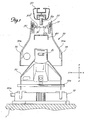
Figure 1 shows a front exploded view, from the inner side, of the foot according to the invention; -
Figure 2 shows a front view, from the inner side, of the foot according toFig. 1 assembled; -
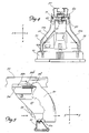
Figure 3 shows a cross-section along the plane indicated by the line III-III inFig. 2 ; -
Figure 4 shows a front view, from the inner side, of the foot according toFig.1 during removal of the cover piece; and -
Figure 5 shows a schematic and partially sectioned side view of the foot according toFig. 4 . - As shown in
Fig. 1 and assuming for the sole sake of convenience of the description and without a limiting meaning a set of three reference axes in the longitudinal direction X-X, transverse direction Y-Y and vertical direction Z-Z, respectively, as well as an outer side corresponding to the side for insertion/extraction of the cover piece and an inner side opposite to the outer side, the support foot for universal carrier bars according to the invention comprises essentially: - a
base 10 for resting on the roof 1 of a vehicle; - a
shaped body 20 hinged with thebase 10 by means of atransverse pin 10a; - The
guide 30 has, moreover, aseat 32 formed on each vertical side of the H and extending in the transverse direction Y-Y and with a T-shaped cross-section; in greater detail, saidseat 32 has (seeFigs. 3 and5 ), in the transverse direction Y-Y, a firstinner section 32 of smaller height Z1 and a second outer section 32b of greater height Z2. - The two
seats 32 in the opposite vertical sides of theguide 30 are suitable for insertion, in the transverse direction, of a respective slide 71 extending in the transverse direction and projecting towards the inside of thecover piece 70 of the foot. - The slide 71 has a T-shaped cross-section and is shaped with a first
inner section 71a of greater height Z2 and a second outer section 71b of smaller height Z1. - The
closing piece 70 has, moreover, twofins 73 projecting towards the inside in the transverse direction Y-Y and arranged in a lower position in the direction Z-Z of thesides 70a of the closing piece itself. - Advantageously, said
sides 70a are elastically deformable outwards following a pulling force applied by the user as will be understood more clearly below. - With this configuration the operating principle of the foot is as follows:
- once the foot has been mounted and the
base 10 assembled with thebody 20 and thetransverse bar 50 positioned on the seat 30b of theguide 30, - the whole assembly is locked by tightening the
bolt 60 with thecorresponding nut 61; - repeating the operation on both ends of the bar, the assembly is made structurally stable by fastening it to the roof 1 of the vehicle.
- The operations are conventional per se and therefore not described in greater detail.
- Once the foot has been assembled it is possible to:
- insert the
cover piece 70 in the transverse direction Y-Y, introducing the slides 71 inside the respectivelateral guides 32 of theguide 30; - during insertion the
slide part 71a with a larger dimension Z2 enters firstly so that, once insertion has been completed, it will be in a transverse position corresponding to the guide part 40a with a smaller dimension Z1, preventing relative movements in the transverse direction. - The particular form of the seats 41 and the
guides 70 also has the function of establishing a unique direction of assembly of theguide 40 on thebody 20; if in fact it were attempted to mount the former in the opposite direction (rotated by 180°), insertion of thecover piece 70 would be prevented by the greater size of the slide 71 compared to that of theseat 32. - During insertion in the transverse direction Y-Y (
Fig. 4 ) the cover piece undergoes, in its bottom part, which is not constrained, an elastic deformation outwards in the transverse longitudinal direction X-X caused by thefins 73 pressing against the sides of thebody 20; - once insertion has been completed, the
fins 73 pass beyond the free edge of theside 20a of thebody 20, allowing the elastic return of theside 70a into the rest condition which brings thefins 73 into a position where they interfere in the transverse direction with the body 20 (Fig. 2 ). - In this way, the cover piece is prevented from extraction in the transverse direction which may be performed only following an intentional action involving widening of its
sides 70a performed by the user (Fig. 4 ). - It is therefore clear how with the support foot for universal carrier bars of vehicles according to the invention it is possible to avoid errors in positioning of the various component parts during assembly of the said foot as well fit onto / remove from the foot the cover piece in a precise manner without the need for tools, ensuring moreover, once insertion has been completed, that the cover piece is firmly secured in the direction parallel to the direction of travel of the vehicle so as to prevent accidental and unwanted removal.
Claims (7)
- Support foot for universal carrier bars of vehicles, comprising:- a base (10) for resting on the roof (1) of the vehicle,- a shaped body (20) hinged with the base (10) by means of a transverse pin (10a),- a guide (30) able to contain a transverse bar (30) and means (60) for locking the assembly in the vertical direction (Z-Z)- a cover piece (70)characterized in that said cover piece (70) has a slide (71) extending in the transverse direction (Y-Y) and projecting towards the inside from each side (70a) of the cover piece (70) itself and able to engage with a respective seat (32) formed in each vertical side of the guide (50),
and in that each side (70a) of the cover piece (70) is elastically deformable outwards and has at least one respective fin (73) projecting towards the inside in the transverse direction (Y-Y). - Foot according to Claim 1, characterized in that said guide (30) is shaped in the form of an H.
- Foot according to Claim 2, characterized in that said guide (30) has a bottom surface (30a) making contact with a metallic flange (40), a top surface (30b) containing a transverse bar (50), and a hole (31) with a vertical axis for receiving means (60) for locking the assembly in the vertical direction (Z-Z).
- Foot according to Claim 2, characterized in that said guide (30) has a seat (32) formed in each vertical side of the H.
- Foot according to Claim 4, characterized in that said seat (32) extends in the transverse direction (Y-Y) and has a T-shaped cross-section.
- Foot according to Claim 4, characterized in that, in the transverse direction (Y-Y), said seat (32) has a first, inner, section (32a) of smaller height Z1 and a second, outer, section (32b) of greater height Z2.
- Foot according to Claim 6, characterized in that each slide (71) has a T-shaped cross-section and is shaped with a first, inner, section (71a) of greater height Z2 and a second, outer, section (71b) of lower height Z1.
Applications Claiming Priority (1)
| Application Number | Priority Date | Filing Date | Title |
|---|---|---|---|
| IT000252U ITMI20070252U1 (en) | 2007-07-17 | 2007-07-17 | SUPPORTING FOOT BAR FOR VEHICLE AND SIMILAR BARS INCLUDING AN INSERTABLE-REMOVABLE CLOSURE ELEMENT |
Publications (3)
| Publication Number | Publication Date |
|---|---|
| EP2017129A2 true EP2017129A2 (en) | 2009-01-21 |
| EP2017129A3 EP2017129A3 (en) | 2010-08-11 |
| EP2017129B1 EP2017129B1 (en) | 2011-10-26 |
Family
ID=39924976
Family Applications (1)
| Application Number | Title | Priority Date | Filing Date |
|---|---|---|---|
| EP08012726A Not-in-force EP2017129B1 (en) | 2007-07-17 | 2008-07-15 | Support foot for vehicle roof carriers bars |
Country Status (3)
| Country | Link |
|---|---|
| EP (1) | EP2017129B1 (en) |
| AT (1) | ATE530385T1 (en) |
| IT (1) | ITMI20070252U1 (en) |
Cited By (2)
| Publication number | Priority date | Publication date | Assignee | Title |
|---|---|---|---|---|
| DE102016221726A1 (en) | 2016-11-07 | 2018-05-09 | Bayerische Motoren Werke Aktiengesellschaft | Vehicle roof rack foot, hereof equipped roof rack and hereby equipped motor vehicle |
| DE102016223890A1 (en) | 2016-12-01 | 2018-06-07 | Bayerische Motoren Werke Aktiengesellschaft | Roof box with cover and hereby equipped motor vehicle |
Citations (3)
| Publication number | Priority date | Publication date | Assignee | Title |
|---|---|---|---|---|
| US4166560A (en) | 1977-10-20 | 1979-09-04 | Siegfried Milke | Cargo carrier for motor vehicles |
| EP1325842A1 (en) | 2001-12-18 | 2003-07-09 | Adam Opel Ag | Theft-resistant roof carrier |
| US20040134951A1 (en) | 2003-01-10 | 2004-07-15 | Watermark Paddlesports, Inc. | Rack tower |
-
2007
- 2007-07-17 IT IT000252U patent/ITMI20070252U1/en unknown
-
2008
- 2008-07-15 EP EP08012726A patent/EP2017129B1/en not_active Not-in-force
- 2008-07-15 AT AT08012726T patent/ATE530385T1/en not_active IP Right Cessation
Patent Citations (3)
| Publication number | Priority date | Publication date | Assignee | Title |
|---|---|---|---|---|
| US4166560A (en) | 1977-10-20 | 1979-09-04 | Siegfried Milke | Cargo carrier for motor vehicles |
| EP1325842A1 (en) | 2001-12-18 | 2003-07-09 | Adam Opel Ag | Theft-resistant roof carrier |
| US20040134951A1 (en) | 2003-01-10 | 2004-07-15 | Watermark Paddlesports, Inc. | Rack tower |
Cited By (4)
| Publication number | Priority date | Publication date | Assignee | Title |
|---|---|---|---|---|
| DE102016221726A1 (en) | 2016-11-07 | 2018-05-09 | Bayerische Motoren Werke Aktiengesellschaft | Vehicle roof rack foot, hereof equipped roof rack and hereby equipped motor vehicle |
| DE102016221726B4 (en) * | 2016-11-07 | 2024-12-24 | Bayerische Motoren Werke Aktiengesellschaft | Vehicle roof rack base, roof rack equipped with it and motor vehicle equipped with it |
| DE102016223890A1 (en) | 2016-12-01 | 2018-06-07 | Bayerische Motoren Werke Aktiengesellschaft | Roof box with cover and hereby equipped motor vehicle |
| DE102016223890B4 (en) | 2016-12-01 | 2023-11-02 | Bayerische Motoren Werke Aktiengesellschaft | Roof box with cover and motor vehicle equipped with it |
Also Published As
| Publication number | Publication date |
|---|---|
| EP2017129B1 (en) | 2011-10-26 |
| ITMI20070252U1 (en) | 2009-01-18 |
| EP2017129A3 (en) | 2010-08-11 |
| ATE530385T1 (en) | 2011-11-15 |
Similar Documents
| Publication | Publication Date | Title |
|---|---|---|
| KR100921297B1 (en) | Luggage room for car | |
| CN108883729B (en) | Modular track and accessory system | |
| US9718410B2 (en) | Assembly for connecting a roof rack to a vehicle | |
| US9045060B2 (en) | Vehicular slide rail device | |
| US9150125B2 (en) | Vehicle slide rail device | |
| JP5522136B2 (en) | Vehicle seat slide device | |
| CN110011197B (en) | Power distribution box assembly with alignment features | |
| EP2017129B1 (en) | Support foot for vehicle roof carriers bars | |
| US7597371B2 (en) | Lead-in for trim assembly | |
| CA2398871C (en) | Integrally formed roof rack | |
| EP2009327A2 (en) | Shift lever apparatus for vehicle | |
| WO2016143874A1 (en) | Knee bolster | |
| EP3849889B1 (en) | Easy-installation top box for saddle vehicle | |
| JP5057307B2 (en) | Spare tire cover mounting structure | |
| US20220289115A1 (en) | Drawer Type Storage Box | |
| JP4202783B2 (en) | Mounting device for backrest in chair | |
| US20190135092A1 (en) | Mounting structure for mounting interior component | |
| JP4874871B2 (en) | Leg cover mounting structure for automobile seats | |
| JP4203580B2 (en) | Vehicle storage device | |
| JP7175953B2 (en) | Center console structure | |
| CN216424155U (en) | Slider for vehicle seat, and seat assembly | |
| CN218198040U (en) | Telescopic handle with spring | |
| JP4423597B2 (en) | Bumper mounting structure | |
| EP1440845B1 (en) | Bracket for securing transverse bars to longitudinal bars fixed to the roof of vehicles and the like | |
| EP2351685B1 (en) | Mudguard for two-wheeled vehicles |
Legal Events
| Date | Code | Title | Description |
|---|---|---|---|
| PUAI | Public reference made under article 153(3) epc to a published international application that has entered the european phase |
Free format text: ORIGINAL CODE: 0009012 |
|
| AK | Designated contracting states |
Kind code of ref document: A2 Designated state(s): AT BE BG CH CY CZ DE DK EE ES FI FR GB GR HR HU IE IS IT LI LT LU LV MC MT NL NO PL PT RO SE SI SK TR |
|
| AX | Request for extension of the european patent |
Extension state: AL BA MK RS |
|
| PUAL | Search report despatched |
Free format text: ORIGINAL CODE: 0009013 |
|
| AK | Designated contracting states |
Kind code of ref document: A3 Designated state(s): AT BE BG CH CY CZ DE DK EE ES FI FR GB GR HR HU IE IS IT LI LT LU LV MC MT NL NO PL PT RO SE SI SK TR |
|
| AX | Request for extension of the european patent |
Extension state: AL BA MK RS |
|
| 17P | Request for examination filed |
Effective date: 20110209 |
|
| AKX | Designation fees paid |
Designated state(s): AT BE BG CH CY CZ DE DK EE ES FI FR GB GR HR HU IE IS IT LI LT LU LV MC MT NL NO PL PT RO SE SI SK TR |
|
| GRAP | Despatch of communication of intention to grant a patent |
Free format text: ORIGINAL CODE: EPIDOSNIGR1 |
|
| RIC1 | Information provided on ipc code assigned before grant |
Ipc: B60R 9/058 20060101ALI20110328BHEP Ipc: B60R 9/05 20060101AFI20110328BHEP |
|
| RIN1 | Information on inventor provided before grant (corrected) |
Inventor name: PRIMAVESI, MARIO |
|
| GRAS | Grant fee paid |
Free format text: ORIGINAL CODE: EPIDOSNIGR3 |
|
| GRAA | (expected) grant |
Free format text: ORIGINAL CODE: 0009210 |
|
| AK | Designated contracting states |
Kind code of ref document: B1 Designated state(s): AT BE BG CH CY CZ DE DK EE ES FI FR GB GR HR HU IE IS IT LI LT LU LV MC MT NL NO PL PT RO SE SI SK TR |
|
| REG | Reference to a national code |
Ref country code: GB Ref legal event code: FG4D |
|
| REG | Reference to a national code |
Ref country code: CH Ref legal event code: EP |
|
| REG | Reference to a national code |
Ref country code: IE Ref legal event code: FG4D |
|
| REG | Reference to a national code |
Ref country code: DE Ref legal event code: R096 Ref document number: 602008010718 Country of ref document: DE Effective date: 20111222 |
|
| REG | Reference to a national code |
Ref country code: NL Ref legal event code: VDEP Effective date: 20111026 |
|
| LTIE | Lt: invalidation of european patent or patent extension |
Effective date: 20111026 |
|
| REG | Reference to a national code |
Ref country code: AT Ref legal event code: MK05 Ref document number: 530385 Country of ref document: AT Kind code of ref document: T Effective date: 20111026 |
|
| PG25 | Lapsed in a contracting state [announced via postgrant information from national office to epo] |
Ref country code: LT Free format text: LAPSE BECAUSE OF FAILURE TO SUBMIT A TRANSLATION OF THE DESCRIPTION OR TO PAY THE FEE WITHIN THE PRESCRIBED TIME-LIMIT Effective date: 20111026 Ref country code: NO Free format text: LAPSE BECAUSE OF FAILURE TO SUBMIT A TRANSLATION OF THE DESCRIPTION OR TO PAY THE FEE WITHIN THE PRESCRIBED TIME-LIMIT Effective date: 20120126 Ref country code: IS Free format text: LAPSE BECAUSE OF FAILURE TO SUBMIT A TRANSLATION OF THE DESCRIPTION OR TO PAY THE FEE WITHIN THE PRESCRIBED TIME-LIMIT Effective date: 20120226 Ref country code: BE Free format text: LAPSE BECAUSE OF FAILURE TO SUBMIT A TRANSLATION OF THE DESCRIPTION OR TO PAY THE FEE WITHIN THE PRESCRIBED TIME-LIMIT Effective date: 20111026 |
|
| PG25 | Lapsed in a contracting state [announced via postgrant information from national office to epo] |
Ref country code: PT Free format text: LAPSE BECAUSE OF FAILURE TO SUBMIT A TRANSLATION OF THE DESCRIPTION OR TO PAY THE FEE WITHIN THE PRESCRIBED TIME-LIMIT Effective date: 20120227 Ref country code: HR Free format text: LAPSE BECAUSE OF FAILURE TO SUBMIT A TRANSLATION OF THE DESCRIPTION OR TO PAY THE FEE WITHIN THE PRESCRIBED TIME-LIMIT Effective date: 20111026 Ref country code: NL Free format text: LAPSE BECAUSE OF FAILURE TO SUBMIT A TRANSLATION OF THE DESCRIPTION OR TO PAY THE FEE WITHIN THE PRESCRIBED TIME-LIMIT Effective date: 20111026 Ref country code: LV Free format text: LAPSE BECAUSE OF FAILURE TO SUBMIT A TRANSLATION OF THE DESCRIPTION OR TO PAY THE FEE WITHIN THE PRESCRIBED TIME-LIMIT Effective date: 20111026 Ref country code: SE Free format text: LAPSE BECAUSE OF FAILURE TO SUBMIT A TRANSLATION OF THE DESCRIPTION OR TO PAY THE FEE WITHIN THE PRESCRIBED TIME-LIMIT Effective date: 20111026 Ref country code: PL Free format text: LAPSE BECAUSE OF FAILURE TO SUBMIT A TRANSLATION OF THE DESCRIPTION OR TO PAY THE FEE WITHIN THE PRESCRIBED TIME-LIMIT Effective date: 20111026 Ref country code: SI Free format text: LAPSE BECAUSE OF FAILURE TO SUBMIT A TRANSLATION OF THE DESCRIPTION OR TO PAY THE FEE WITHIN THE PRESCRIBED TIME-LIMIT Effective date: 20111026 Ref country code: GR Free format text: LAPSE BECAUSE OF FAILURE TO SUBMIT A TRANSLATION OF THE DESCRIPTION OR TO PAY THE FEE WITHIN THE PRESCRIBED TIME-LIMIT Effective date: 20120127 |
|
| PG25 | Lapsed in a contracting state [announced via postgrant information from national office to epo] |
Ref country code: CY Free format text: LAPSE BECAUSE OF FAILURE TO SUBMIT A TRANSLATION OF THE DESCRIPTION OR TO PAY THE FEE WITHIN THE PRESCRIBED TIME-LIMIT Effective date: 20111026 |
|
| PG25 | Lapsed in a contracting state [announced via postgrant information from national office to epo] |
Ref country code: SK Free format text: LAPSE BECAUSE OF FAILURE TO SUBMIT A TRANSLATION OF THE DESCRIPTION OR TO PAY THE FEE WITHIN THE PRESCRIBED TIME-LIMIT Effective date: 20111026 Ref country code: EE Free format text: LAPSE BECAUSE OF FAILURE TO SUBMIT A TRANSLATION OF THE DESCRIPTION OR TO PAY THE FEE WITHIN THE PRESCRIBED TIME-LIMIT Effective date: 20111026 Ref country code: BG Free format text: LAPSE BECAUSE OF FAILURE TO SUBMIT A TRANSLATION OF THE DESCRIPTION OR TO PAY THE FEE WITHIN THE PRESCRIBED TIME-LIMIT Effective date: 20120126 Ref country code: CZ Free format text: LAPSE BECAUSE OF FAILURE TO SUBMIT A TRANSLATION OF THE DESCRIPTION OR TO PAY THE FEE WITHIN THE PRESCRIBED TIME-LIMIT Effective date: 20111026 Ref country code: DK Free format text: LAPSE BECAUSE OF FAILURE TO SUBMIT A TRANSLATION OF THE DESCRIPTION OR TO PAY THE FEE WITHIN THE PRESCRIBED TIME-LIMIT Effective date: 20111026 |
|
| PG25 | Lapsed in a contracting state [announced via postgrant information from national office to epo] |
Ref country code: RO Free format text: LAPSE BECAUSE OF FAILURE TO SUBMIT A TRANSLATION OF THE DESCRIPTION OR TO PAY THE FEE WITHIN THE PRESCRIBED TIME-LIMIT Effective date: 20111026 Ref country code: IT Free format text: LAPSE BECAUSE OF FAILURE TO SUBMIT A TRANSLATION OF THE DESCRIPTION OR TO PAY THE FEE WITHIN THE PRESCRIBED TIME-LIMIT Effective date: 20111026 |
|
| PLBE | No opposition filed within time limit |
Free format text: ORIGINAL CODE: 0009261 |
|
| STAA | Information on the status of an ep patent application or granted ep patent |
Free format text: STATUS: NO OPPOSITION FILED WITHIN TIME LIMIT |
|
| 26N | No opposition filed |
Effective date: 20120727 |
|
| REG | Reference to a national code |
Ref country code: DE Ref legal event code: R097 Ref document number: 602008010718 Country of ref document: DE Effective date: 20120727 |
|
| PG25 | Lapsed in a contracting state [announced via postgrant information from national office to epo] |
Ref country code: AT Free format text: LAPSE BECAUSE OF FAILURE TO SUBMIT A TRANSLATION OF THE DESCRIPTION OR TO PAY THE FEE WITHIN THE PRESCRIBED TIME-LIMIT Effective date: 20111026 |
|
| PG25 | Lapsed in a contracting state [announced via postgrant information from national office to epo] |
Ref country code: MC Free format text: LAPSE BECAUSE OF NON-PAYMENT OF DUE FEES Effective date: 20120731 |
|
| REG | Reference to a national code |
Ref country code: CH Ref legal event code: PL |
|
| GBPC | Gb: european patent ceased through non-payment of renewal fee |
Effective date: 20120715 |
|
| REG | Reference to a national code |
Ref country code: FR Ref legal event code: ST Effective date: 20130329 |
|
| PG25 | Lapsed in a contracting state [announced via postgrant information from national office to epo] |
Ref country code: LI Free format text: LAPSE BECAUSE OF NON-PAYMENT OF DUE FEES Effective date: 20120731 Ref country code: FR Free format text: LAPSE BECAUSE OF NON-PAYMENT OF DUE FEES Effective date: 20120731 Ref country code: ES Free format text: LAPSE BECAUSE OF FAILURE TO SUBMIT A TRANSLATION OF THE DESCRIPTION OR TO PAY THE FEE WITHIN THE PRESCRIBED TIME-LIMIT Effective date: 20120206 Ref country code: GB Free format text: LAPSE BECAUSE OF NON-PAYMENT OF DUE FEES Effective date: 20120715 Ref country code: CH Free format text: LAPSE BECAUSE OF NON-PAYMENT OF DUE FEES Effective date: 20120731 Ref country code: DE Free format text: LAPSE BECAUSE OF NON-PAYMENT OF DUE FEES Effective date: 20130201 |
|
| REG | Reference to a national code |
Ref country code: IE Ref legal event code: MM4A |
|
| REG | Reference to a national code |
Ref country code: DE Ref legal event code: R119 Ref document number: 602008010718 Country of ref document: DE Effective date: 20130201 |
|
| PG25 | Lapsed in a contracting state [announced via postgrant information from national office to epo] |
Ref country code: FI Free format text: LAPSE BECAUSE OF FAILURE TO SUBMIT A TRANSLATION OF THE DESCRIPTION OR TO PAY THE FEE WITHIN THE PRESCRIBED TIME-LIMIT Effective date: 20111026 |
|
| PG25 | Lapsed in a contracting state [announced via postgrant information from national office to epo] |
Ref country code: MT Free format text: LAPSE BECAUSE OF FAILURE TO SUBMIT A TRANSLATION OF THE DESCRIPTION OR TO PAY THE FEE WITHIN THE PRESCRIBED TIME-LIMIT Effective date: 20111026 Ref country code: IE Free format text: LAPSE BECAUSE OF NON-PAYMENT OF DUE FEES Effective date: 20120715 |
|
| PG25 | Lapsed in a contracting state [announced via postgrant information from national office to epo] |
Ref country code: TR Free format text: LAPSE BECAUSE OF FAILURE TO SUBMIT A TRANSLATION OF THE DESCRIPTION OR TO PAY THE FEE WITHIN THE PRESCRIBED TIME-LIMIT Effective date: 20111026 |
|
| PG25 | Lapsed in a contracting state [announced via postgrant information from national office to epo] |
Ref country code: LU Free format text: LAPSE BECAUSE OF NON-PAYMENT OF DUE FEES Effective date: 20120715 |
|
| PG25 | Lapsed in a contracting state [announced via postgrant information from national office to epo] |
Ref country code: HU Free format text: LAPSE BECAUSE OF FAILURE TO SUBMIT A TRANSLATION OF THE DESCRIPTION OR TO PAY THE FEE WITHIN THE PRESCRIBED TIME-LIMIT Effective date: 20080715 |