EP2017113A1 - Method and system for fitting one or more additional tanks to a tank of an industrial or commercial vehicle - Google Patents
Method and system for fitting one or more additional tanks to a tank of an industrial or commercial vehicle Download PDFInfo
- Publication number
- EP2017113A1 EP2017113A1 EP08157543A EP08157543A EP2017113A1 EP 2017113 A1 EP2017113 A1 EP 2017113A1 EP 08157543 A EP08157543 A EP 08157543A EP 08157543 A EP08157543 A EP 08157543A EP 2017113 A1 EP2017113 A1 EP 2017113A1
- Authority
- EP
- European Patent Office
- Prior art keywords
- tank
- wall
- couplings
- additional tanks
- industrial
- Prior art date
- Legal status (The legal status is an assumption and is not a legal conclusion. Google has not performed a legal analysis and makes no representation as to the accuracy of the status listed.)
- Granted
Links
Images

Classifications
-
- B—PERFORMING OPERATIONS; TRANSPORTING
- B60—VEHICLES IN GENERAL
- B60K—ARRANGEMENT OR MOUNTING OF PROPULSION UNITS OR OF TRANSMISSIONS IN VEHICLES; ARRANGEMENT OR MOUNTING OF PLURAL DIVERSE PRIME-MOVERS IN VEHICLES; AUXILIARY DRIVES FOR VEHICLES; INSTRUMENTATION OR DASHBOARDS FOR VEHICLES; ARRANGEMENTS IN CONNECTION WITH COOLING, AIR INTAKE, GAS EXHAUST OR FUEL SUPPLY OF PROPULSION UNITS IN VEHICLES
- B60K15/00—Arrangement in connection with fuel supply of combustion engines or other fuel consuming energy converters, e.g. fuel cells; Mounting or construction of fuel tanks
- B60K15/03—Fuel tanks
- B60K15/063—Arrangement of tanks
-
- B—PERFORMING OPERATIONS; TRANSPORTING
- B60—VEHICLES IN GENERAL
- B60K—ARRANGEMENT OR MOUNTING OF PROPULSION UNITS OR OF TRANSMISSIONS IN VEHICLES; ARRANGEMENT OR MOUNTING OF PLURAL DIVERSE PRIME-MOVERS IN VEHICLES; AUXILIARY DRIVES FOR VEHICLES; INSTRUMENTATION OR DASHBOARDS FOR VEHICLES; ARRANGEMENTS IN CONNECTION WITH COOLING, AIR INTAKE, GAS EXHAUST OR FUEL SUPPLY OF PROPULSION UNITS IN VEHICLES
- B60K13/00—Arrangement in connection with combustion air intake or gas exhaust of propulsion units
- B60K13/04—Arrangement in connection with combustion air intake or gas exhaust of propulsion units concerning exhaust
-
- B—PERFORMING OPERATIONS; TRANSPORTING
- B60—VEHICLES IN GENERAL
- B60K—ARRANGEMENT OR MOUNTING OF PROPULSION UNITS OR OF TRANSMISSIONS IN VEHICLES; ARRANGEMENT OR MOUNTING OF PLURAL DIVERSE PRIME-MOVERS IN VEHICLES; AUXILIARY DRIVES FOR VEHICLES; INSTRUMENTATION OR DASHBOARDS FOR VEHICLES; ARRANGEMENTS IN CONNECTION WITH COOLING, AIR INTAKE, GAS EXHAUST OR FUEL SUPPLY OF PROPULSION UNITS IN VEHICLES
- B60K15/00—Arrangement in connection with fuel supply of combustion engines or other fuel consuming energy converters, e.g. fuel cells; Mounting or construction of fuel tanks
- B60K15/03—Fuel tanks
- B60K2015/03118—Multiple tanks, i.e. two or more separate tanks
- B60K2015/03151—Mechanical connection between the tanks
-
- B—PERFORMING OPERATIONS; TRANSPORTING
- B60—VEHICLES IN GENERAL
- B60K—ARRANGEMENT OR MOUNTING OF PROPULSION UNITS OR OF TRANSMISSIONS IN VEHICLES; ARRANGEMENT OR MOUNTING OF PLURAL DIVERSE PRIME-MOVERS IN VEHICLES; AUXILIARY DRIVES FOR VEHICLES; INSTRUMENTATION OR DASHBOARDS FOR VEHICLES; ARRANGEMENTS IN CONNECTION WITH COOLING, AIR INTAKE, GAS EXHAUST OR FUEL SUPPLY OF PROPULSION UNITS IN VEHICLES
- B60K15/00—Arrangement in connection with fuel supply of combustion engines or other fuel consuming energy converters, e.g. fuel cells; Mounting or construction of fuel tanks
- B60K15/03—Fuel tanks
- B60K2015/03328—Arrangements or special measures related to fuel tanks or fuel handling
- B60K2015/03348—Arrangements or special measures related to fuel tanks or fuel handling for supplying additives to fuel
Definitions
- the present invention relates to a method and system for fitting one or more additional tanks to a tank of an industrial or commercial vehicle.
- fluid tanks As far as fluid tanks are concerned, their number increases as the "industrial vehicle" machine becomes more complex and, in addition to transporting goods, is required to fulfil other related functions, such as ensuring comfort, providing tanks for water or fulfilling other functions as required by fitters, for instance to meet environmental standards as in the case of the new propulsion systems with reduced environmental impact.
- one new requirement concerns the space required to house one or more additional tanks, for instance the urea tank, which is essential for latest generation diesel engines to operate, or tanks of water for the driver or arrangements for other liquids installed by the fitter to hold oil, detergent, etc.
- the purpose of the present invention is to describe a method and system for fitting one or more additional tanks to a tank of an industrial or commercial vehicle which reduces the overall amount of space that is taken up, reduces the number of additional supports, and also the time and costs involved in production.
- the present invention relates to a method and relative system for fitting one or more additional tanks to a tank of an industrial or commercial vehicle, characterized in that this is achieved by means of one or more "dovetail" couplings between said tank and said one or more additional tanks, on one or more facing walls between said tank and one or more additional tanks.
- the invention relates in particular to a method and system for fitting one or more additional tanks to a tank of an industrial or commercial vehicle, as described more fully in the claims, which are an integral part of this description.
- number 1 indicates a main tank of an industrial or commercial vehicle, said tank being basically parallelepiped in shape, for example a diesel tank, while number 2 indicates an additional tank of an industrial or commercial vehicle, said additional tank also being basically parallelepiped in shape, for example a tank for urea.
- the two tanks are fitted together preferably by means of a "dovetail” coupling with vertical bayonet joint 3, 4, on the facing side walls of the two tanks.
- One of the two parts of the coupling for example that on the main tank 1, comprises a blind trapeziform recess 4 in the side wall of the tank, which starts at its widest part on the upper edge of the wall, continues on the wall with two convergent edges, and ends on the same wall, in a blind end.
- the convergent side walls are shaped so as to achieve a coupling, in that they are provided with notch-type recesses with respect to the outside edges.
- the other part of the coupling for example on the additional tank 2, comprises a shape that is complementary to that of the wall of the tank 1, in that the side wall of the tank of provided with a trapeziform protuberance 3, which starts at its widest part on the upper edge of the wall, continues on the wall with two convergent edges, and ends on the same wall, in a blind end.
- the convergent side walls are shaped so as to achieve a coupling, in that they are provided with divergent raised protuberances, complementary to the notch-type recess on the main tank 1.
- the additional tank 2 is arranged so as to face the main tank 1 laterally and superiorly, the two complementary forms of the coupling are brought together and the protuberance 4 is inserted completely into the recess 3, to achieve the stable and effective coupling as illustrated in fig. 3 .
- FIG. 4 illustrates an alternative embodiment in which the tanks are fitted together in a similar way but by means of a horizontal coupling instead of a vertical coupling.
- This alternative is useful in cases in which there is not enough space above the main tank to fit the additional tank, without removing the main tank, for example due to the presence of a fixed trailer only a small distance above the tanks. In this case there may be an extra bracket 5 to support the additional tank, to prevent it from slipping forwards and leaving its seat.
- the couplings can be achieved on more than one wall of the main tank, for example on the side walls and/or upper and/or lower walls, with vertical or horizontal couplings.
- the "dovetail” couplings can also be of the through type, that is they can occupy the whole of the facing walls, starting from one edge of the wall and ending on the opposite edge.
- the recessed part of the "dovetail” couplings can be on either of the two facing walls, and the corresponding protruding part on the other wall.
- the extra supporting brackets are not always necessary, but are useful if the additional tanks are too heavy to be supported by the main tank alone.
- a reduction in the overall dimensions of the components and fastenings is obtained, for example by eliminating one or more of the supports for the additional tanks, since the main tank also supports the others; moreover the use of a preassembled tank improves the assembly process on the production line and cuts assembly times.
Landscapes
- Engineering & Computer Science (AREA)
- Chemical & Material Sciences (AREA)
- Combustion & Propulsion (AREA)
- Transportation (AREA)
- Mechanical Engineering (AREA)
- Life Sciences & Earth Sciences (AREA)
- Sustainable Development (AREA)
- Sustainable Energy (AREA)
- Details Of Rigid Or Semi-Rigid Containers (AREA)
- Ship Loading And Unloading (AREA)
- Exhaust Gas After Treatment (AREA)
- Cooling, Air Intake And Gas Exhaust, And Fuel Tank Arrangements In Propulsion Units (AREA)
Abstract
Description
- The present invention relates to a method and system for fitting one or more additional tanks to a tank of an industrial or commercial vehicle.
- For industrial or commercial vehicles it is increasingly important to reduce the overall dimensions and optimize production processes.
- As far as fluid tanks are concerned, their number increases as the "industrial vehicle" machine becomes more complex and, in addition to transporting goods, is required to fulfil other related functions, such as ensuring comfort, providing tanks for water or fulfilling other functions as required by fitters, for instance to meet environmental standards as in the case of the new propulsion systems with reduced environmental impact. For instance one new requirement concerns the space required to house one or more additional tanks, for instance the urea tank, which is essential for latest generation diesel engines to operate, or tanks of water for the driver or arrangements for other liquids installed by the fitter to hold oil, detergent, etc.
- Therefore the purpose of the present invention is to describe a method and system for fitting one or more additional tanks to a tank of an industrial or commercial vehicle which reduces the overall amount of space that is taken up, reduces the number of additional supports, and also the time and costs involved in production.
- The present invention relates to a method and relative system for fitting one or more additional tanks to a tank of an industrial or commercial vehicle, characterized in that this is achieved by means of one or more "dovetail" couplings between said tank and said one or more additional tanks, on one or more facing walls between said tank and one or more additional tanks.
- The invention relates in particular to a method and system for fitting one or more additional tanks to a tank of an industrial or commercial vehicle, as described more fully in the claims, which are an integral part of this description.
- Further purposes and advantages of this invention will become apparent from the following detailed description of a preferred embodiment thereof (and the relative alternative embodiments) and the drawings that are attached hereto, which are merely illustrative and not limitative, in which:
-
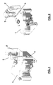
figures 1 and 2 are two isometric views of the system for fitting an additional tank to a main tank, according to the present invention, before inserting the additional tank into the main tank; -
figure 3 is an isometric view of the coupling system shown infigures 1 and 2 , after inserting the additional tank into the main tank; -
figure 4 shows an alternative embodiment of the coupling system. - In the figures the same reference numbers are used to indicate the same components.
- In
figures 1 and 2 , number 1 indicates a main tank of an industrial or commercial vehicle, said tank being basically parallelepiped in shape, for example a diesel tank, whilenumber 2 indicates an additional tank of an industrial or commercial vehicle, said additional tank also being basically parallelepiped in shape, for example a tank for urea. - The two tanks are fitted together preferably by means of a "dovetail" coupling with
vertical bayonet joint 3, 4, on the facing side walls of the two tanks. - One of the two parts of the coupling, for example that on the main tank 1, comprises a blind trapeziform recess 4 in the side wall of the tank, which starts at its widest part on the upper edge of the wall, continues on the wall with two convergent edges, and ends on the same wall, in a blind end. The convergent side walls are shaped so as to achieve a coupling, in that they are provided with notch-type recesses with respect to the outside edges.
- The other part of the coupling, for example on the
additional tank 2, comprises a shape that is complementary to that of the wall of the tank 1, in that the side wall of the tank of provided with atrapeziform protuberance 3, which starts at its widest part on the upper edge of the wall, continues on the wall with two convergent edges, and ends on the same wall, in a blind end. The convergent side walls are shaped so as to achieve a coupling, in that they are provided with divergent raised protuberances, complementary to the notch-type recess on the main tank 1. - During assembly, the
additional tank 2 is arranged so as to face the main tank 1 laterally and superiorly, the two complementary forms of the coupling are brought together and the protuberance 4 is inserted completely into therecess 3, to achieve the stable and effective coupling as illustrated infig. 3 . - There is generally no need for any extra supports for the
additional tank 2, since thecoupling 3, 4 is sufficient to hold the additional tank in place cantilevered sideways from the side of the main tank 1. - The only design requirement is that the shape and dimensions of the two side walls of the two tanks must be equal and complementary, in order to obtain the best coupling.
-
Figure 4 illustrates an alternative embodiment in which the tanks are fitted together in a similar way but by means of a horizontal coupling instead of a vertical coupling. This alternative is useful in cases in which there is not enough space above the main tank to fit the additional tank, without removing the main tank, for example due to the presence of a fixed trailer only a small distance above the tanks. In this case there may be anextra bracket 5 to support the additional tank, to prevent it from slipping forwards and leaving its seat. - In any case the use of a dovetail coupling (whether from the top or side) makes it possible to eliminate two brackets, or just one bracket if the additional tank is too heavy.
- It will be apparent to the person skilled in the art that other alternative and equivalent embodiments of the invention can be conceived and reduced to practice without departing from the true spirit of the invention.
- For example several additional tanks can be inserted in series, with similar "dovetail" couplings, to be achieved on the corresponding facing walls.
- The couplings can be achieved on more than one wall of the main tank, for example on the side walls and/or upper and/or lower walls, with vertical or horizontal couplings.
- The "dovetail" couplings can also be of the through type, that is they can occupy the whole of the facing walls, starting from one edge of the wall and ending on the opposite edge.
- The recessed part of the "dovetail" couplings can be on either of the two facing walls, and the corresponding protruding part on the other wall.
- The extra supporting brackets are not always necessary, but are useful if the additional tanks are too heavy to be supported by the main tank alone.
- The advantages deriving from the application of the present invention are clear.
- A reduction in the overall dimensions of the components and fastenings is obtained, for example by eliminating one or more of the supports for the additional tanks, since the main tank also supports the others; moreover the use of a preassembled tank improves the assembly process on the production line and cuts assembly times.
- From the description set forth above it will be possible for the person skilled in the art to embody the invention without introducing any further construction details.
Claims (8)
- Method of fitting one or more additional tanks to a tank of an industrial or commercial vehicle, characterized in that this is achieved by means of one or more "dovetail" couplings between said tank (1) and said one or more additional tanks (2), on one or more facing walls between said tank and one or more additional tanks.
- System of fitting one or more additional tanks to a tank of an industrial or commercial vehicle, characterized in that it comprises one or more "dovetail" couplings (3, 4) between said tank (1) and said one or more additional tanks (2), on one or more facing walls between said tank and one or more additional tanks.
- Coupling system according to claim 2, characterized in that said one or more couplings (3, 4) are achieved on one or more side and/or upper and/or lower facing walls.
- Coupling system according to claim 2, characterized in that said one or more "dovetail" couplings (3, 4) comprise vertical or horizontal couplings.
- Coupling system according to any of the claims from 2 to 4, characterized in that each of said one or more "dovetail" couplings comprises:- a first part comprising a blind recess (4) in one of the two facing walls, which starts at its widest part on one edge of the wall, continues on the wall with two convergent edges, and ends on the same wall, in a blind end;- a second part comprising a blind protuberance (3) complementary to said blind recess (4), in the other facing wall, which starts at its widest part on one edge of the wall, continues on the wall with two convergent edges, and ends on the same wall, in a blind end, said first and second parts forming a coupling.
- Coupling system according to any of the claims from 2 to 4, characterized in that each of said one or more "dovetail" couplings comprises:- a third part comprising a through recess in one of the two facing walls, that starts at its widest part on one edge of the wall, continues on the wall with two convergent edges, and ends on the opposite edge of the same wall;- a fourth part comprising a through protuberance complementary to said through recess, in the other facing wall, that starts at its widest part on one edge of the wall, continues on the wall with two convergent edges, and ends on the opposite edge of the same wall, said third and fourth parts forming a coupling.
- Coupling system according to any of the previous claims, characterized in that it comprises one or more extra supporting brackets (5) for the corresponding additional tanks.
- Tank assembly for industrial or commercial vehicle, comprising at least one main tank (1) and one or more additional tanks (2) fitted together by means of said one or more couplings according to any of the claims from 2 to 7.
Applications Claiming Priority (1)
| Application Number | Priority Date | Filing Date | Title |
|---|---|---|---|
| IT001156A ITMI20071156A1 (en) | 2007-06-06 | 2007-06-06 | METHOD AND SYSTEM OF COUPLING ONE OR MORE TANKS TO AN ADDITIONAL OR COMMERCIAL VEHICLE TANK |
Publications (2)
| Publication Number | Publication Date |
|---|---|
| EP2017113A1 true EP2017113A1 (en) | 2009-01-21 |
| EP2017113B1 EP2017113B1 (en) | 2013-05-22 |
Family
ID=38434743
Family Applications (1)
| Application Number | Title | Priority Date | Filing Date |
|---|---|---|---|
| EP08157543.3A Active EP2017113B1 (en) | 2007-06-06 | 2008-06-04 | Method and system for fitting one or more additional tanks to a tank of an industrial or commercial vehicle |
Country Status (4)
| Country | Link |
|---|---|
| EP (1) | EP2017113B1 (en) |
| CN (1) | CN101412365B (en) |
| ES (1) | ES2424133T3 (en) |
| IT (1) | ITMI20071156A1 (en) |
Cited By (2)
| Publication number | Priority date | Publication date | Assignee | Title |
|---|---|---|---|---|
| DE102015004704A1 (en) * | 2014-04-15 | 2015-10-15 | Scania Cv Ab | Rotatable fuel tank, especially intended for vehicles |
| EP4414199A1 (en) * | 2023-02-08 | 2024-08-14 | Kubota Corporation | Improved tank for a work vehicle |
Families Citing this family (1)
| Publication number | Priority date | Publication date | Assignee | Title |
|---|---|---|---|---|
| CN106314132B (en) * | 2016-09-22 | 2019-06-14 | 中联重机股份有限公司 | A kind of motor vehicle multifunctional fuel tank |
Citations (4)
| Publication number | Priority date | Publication date | Assignee | Title |
|---|---|---|---|---|
| WO1993012946A1 (en) * | 1991-12-23 | 1993-07-08 | Saab-Scania Aktiebolag | Fuel tank arrangement for motor vehicles |
| US6223526B1 (en) * | 1998-06-17 | 2001-05-01 | Siemens Aktiengesellschaft | Dual compartment fuel storage tank |
| EP1645452A1 (en) * | 2004-10-08 | 2006-04-12 | Iveco S.p.A. | Integrated tank for urea, vehicle provided with this tank and method for storing urea solutions on a vehicle |
| EP1736350A2 (en) | 2005-06-24 | 2006-12-27 | MAN Nutzfahrzeuge Aktiengesellschaft | Vehicle with a reducing agent reservoir for an exhaust gas cleaning device |
Family Cites Families (1)
| Publication number | Priority date | Publication date | Assignee | Title |
|---|---|---|---|---|
| CN2858511Y (en) * | 2005-07-15 | 2007-01-17 | 秦川 | Combined bottle |
-
2007
- 2007-06-06 IT IT001156A patent/ITMI20071156A1/en unknown
-
2008
- 2008-06-02 CN CN200810100079XA patent/CN101412365B/en active Active
- 2008-06-04 ES ES08157543T patent/ES2424133T3/en active Active
- 2008-06-04 EP EP08157543.3A patent/EP2017113B1/en active Active
Patent Citations (4)
| Publication number | Priority date | Publication date | Assignee | Title |
|---|---|---|---|---|
| WO1993012946A1 (en) * | 1991-12-23 | 1993-07-08 | Saab-Scania Aktiebolag | Fuel tank arrangement for motor vehicles |
| US6223526B1 (en) * | 1998-06-17 | 2001-05-01 | Siemens Aktiengesellschaft | Dual compartment fuel storage tank |
| EP1645452A1 (en) * | 2004-10-08 | 2006-04-12 | Iveco S.p.A. | Integrated tank for urea, vehicle provided with this tank and method for storing urea solutions on a vehicle |
| EP1736350A2 (en) | 2005-06-24 | 2006-12-27 | MAN Nutzfahrzeuge Aktiengesellschaft | Vehicle with a reducing agent reservoir for an exhaust gas cleaning device |
Cited By (3)
| Publication number | Priority date | Publication date | Assignee | Title |
|---|---|---|---|---|
| DE102015004704A1 (en) * | 2014-04-15 | 2015-10-15 | Scania Cv Ab | Rotatable fuel tank, especially intended for vehicles |
| EP4414199A1 (en) * | 2023-02-08 | 2024-08-14 | Kubota Corporation | Improved tank for a work vehicle |
| US12434552B2 (en) | 2023-02-08 | 2025-10-07 | Kubota Corporation | Tank for a work vehicle |
Also Published As
| Publication number | Publication date |
|---|---|
| CN101412365A (en) | 2009-04-22 |
| ITMI20071156A1 (en) | 2008-12-07 |
| EP2017113B1 (en) | 2013-05-22 |
| CN101412365B (en) | 2013-10-16 |
| ES2424133T3 (en) | 2013-09-27 |
Similar Documents
| Publication | Publication Date | Title |
|---|---|---|
| US4357027A (en) | Motor vehicle fuel tank | |
| US20100282758A1 (en) | Interlocking Hollow Tanks | |
| EP2017113B1 (en) | Method and system for fitting one or more additional tanks to a tank of an industrial or commercial vehicle | |
| EP2800669B1 (en) | Fluid container for a motor vehicle | |
| US20030015536A1 (en) | Fuel tank | |
| JP5794923B2 (en) | Bracket for vehicle | |
| US20130284749A1 (en) | Fuel tank assembly | |
| EP2916017A1 (en) | Noise reduction baffle and method for installing same | |
| CN104421993B (en) | Lubricating cup and range hood used for range hood | |
| JP2019039500A (en) | Anti-vibration stand | |
| CN208602315U (en) | A kind of hydraulic oil and diesel oil composite fuel case | |
| EP2075150A2 (en) | Pressure Vessel | |
| JP2017223145A (en) | Fixation structure of vehicular tank | |
| US20080296395A1 (en) | Fuel Extraction System for an Auxiliary Heating Unit | |
| KR101067169B1 (en) | Baffle Structure of Fuel Tank | |
| JP5792445B2 (en) | Fuel filter mounting structure | |
| US20130161249A1 (en) | In-tank filter for fuel pump module | |
| CN107709717B (en) | Installation structure of reducing agent tank | |
| CN116834846A (en) | Vehicle body structure and vehicle | |
| CN210106041U (en) | Flange support piece fuel pump | |
| KR101335023B1 (en) | Noise Pump Fuel Pump Module | |
| JP2019098793A (en) | Reinforcement structure of rear side member | |
| EP1308373A1 (en) | Multi-functional container for the engine compartment of motor vehicles | |
| CN107795417A (en) | Fuel filter assembly and vehicle | |
| CN104015607A (en) | Installation structure for automobile radiator |
Legal Events
| Date | Code | Title | Description |
|---|---|---|---|
| PUAI | Public reference made under article 153(3) epc to a published international application that has entered the european phase |
Free format text: ORIGINAL CODE: 0009012 |
|
| PUAI | Public reference made under article 153(3) epc to a published international application that has entered the european phase |
Free format text: ORIGINAL CODE: 0009012 |
|
| AK | Designated contracting states |
Kind code of ref document: A1 Designated state(s): AT BE BG CH CY CZ DE DK EE ES FI FR GB GR HR HU IE IS IT LI LT LU LV MC MT NL NO PL PT RO SE SI SK TR |
|
| AX | Request for extension of the european patent |
Extension state: AL BA MK RS |
|
| 17P | Request for examination filed |
Effective date: 20090720 |
|
| 17Q | First examination report despatched |
Effective date: 20090817 |
|
| AKX | Designation fees paid |
Designated state(s): AT BE BG CH CY CZ DE DK EE ES FI FR GB GR HR HU IE IS IT LI LT LU LV MC MT NL NO PL PT RO SE SI SK TR |
|
| GRAP | Despatch of communication of intention to grant a patent |
Free format text: ORIGINAL CODE: EPIDOSNIGR1 |
|
| GRAS | Grant fee paid |
Free format text: ORIGINAL CODE: EPIDOSNIGR3 |
|
| GRAA | (expected) grant |
Free format text: ORIGINAL CODE: 0009210 |
|
| AK | Designated contracting states |
Kind code of ref document: B1 Designated state(s): AT BE BG CH CY CZ DE DK EE ES FI FR GB GR HR HU IE IS IT LI LT LU LV MC MT NL NO PL PT RO SE SI SK TR |
|
| REG | Reference to a national code |
Ref country code: GB Ref legal event code: FG4D |
|
| REG | Reference to a national code |
Ref country code: CH Ref legal event code: EP |
|
| REG | Reference to a national code |
Ref country code: AT Ref legal event code: REF Ref document number: 613024 Country of ref document: AT Kind code of ref document: T Effective date: 20130615 |
|
| REG | Reference to a national code |
Ref country code: IE Ref legal event code: FG4D |
|
| REG | Reference to a national code |
Ref country code: DE Ref legal event code: R096 Ref document number: 602008024713 Country of ref document: DE Effective date: 20130718 |
|
| REG | Reference to a national code |
Ref country code: SE Ref legal event code: TRGR |
|
| REG | Reference to a national code |
Ref country code: ES Ref legal event code: FG2A Ref document number: 2424133 Country of ref document: ES Kind code of ref document: T3 Effective date: 20130927 |
|
| REG | Reference to a national code |
Ref country code: NL Ref legal event code: T3 |
|
| REG | Reference to a national code |
Ref country code: AT Ref legal event code: MK05 Ref document number: 613024 Country of ref document: AT Kind code of ref document: T Effective date: 20130522 |
|
| REG | Reference to a national code |
Ref country code: LT Ref legal event code: MG4D |
|
| PG25 | Lapsed in a contracting state [announced via postgrant information from national office to epo] |
Ref country code: SI Free format text: LAPSE BECAUSE OF FAILURE TO SUBMIT A TRANSLATION OF THE DESCRIPTION OR TO PAY THE FEE WITHIN THE PRESCRIBED TIME-LIMIT Effective date: 20130522 Ref country code: GR Free format text: LAPSE BECAUSE OF FAILURE TO SUBMIT A TRANSLATION OF THE DESCRIPTION OR TO PAY THE FEE WITHIN THE PRESCRIBED TIME-LIMIT Effective date: 20130823 Ref country code: AT Free format text: LAPSE BECAUSE OF FAILURE TO SUBMIT A TRANSLATION OF THE DESCRIPTION OR TO PAY THE FEE WITHIN THE PRESCRIBED TIME-LIMIT Effective date: 20130522 Ref country code: PT Free format text: LAPSE BECAUSE OF FAILURE TO SUBMIT A TRANSLATION OF THE DESCRIPTION OR TO PAY THE FEE WITHIN THE PRESCRIBED TIME-LIMIT Effective date: 20130923 Ref country code: IS Free format text: LAPSE BECAUSE OF FAILURE TO SUBMIT A TRANSLATION OF THE DESCRIPTION OR TO PAY THE FEE WITHIN THE PRESCRIBED TIME-LIMIT Effective date: 20130922 Ref country code: FI Free format text: LAPSE BECAUSE OF FAILURE TO SUBMIT A TRANSLATION OF THE DESCRIPTION OR TO PAY THE FEE WITHIN THE PRESCRIBED TIME-LIMIT Effective date: 20130522 Ref country code: NO Free format text: LAPSE BECAUSE OF FAILURE TO SUBMIT A TRANSLATION OF THE DESCRIPTION OR TO PAY THE FEE WITHIN THE PRESCRIBED TIME-LIMIT Effective date: 20130822 Ref country code: LT Free format text: LAPSE BECAUSE OF FAILURE TO SUBMIT A TRANSLATION OF THE DESCRIPTION OR TO PAY THE FEE WITHIN THE PRESCRIBED TIME-LIMIT Effective date: 20130522 |
|
| PG25 | Lapsed in a contracting state [announced via postgrant information from national office to epo] |
Ref country code: PL Free format text: LAPSE BECAUSE OF FAILURE TO SUBMIT A TRANSLATION OF THE DESCRIPTION OR TO PAY THE FEE WITHIN THE PRESCRIBED TIME-LIMIT Effective date: 20130522 Ref country code: HR Free format text: LAPSE BECAUSE OF FAILURE TO SUBMIT A TRANSLATION OF THE DESCRIPTION OR TO PAY THE FEE WITHIN THE PRESCRIBED TIME-LIMIT Effective date: 20130522 Ref country code: BG Free format text: LAPSE BECAUSE OF FAILURE TO SUBMIT A TRANSLATION OF THE DESCRIPTION OR TO PAY THE FEE WITHIN THE PRESCRIBED TIME-LIMIT Effective date: 20130822 |
|
| PG25 | Lapsed in a contracting state [announced via postgrant information from national office to epo] |
Ref country code: LV Free format text: LAPSE BECAUSE OF FAILURE TO SUBMIT A TRANSLATION OF THE DESCRIPTION OR TO PAY THE FEE WITHIN THE PRESCRIBED TIME-LIMIT Effective date: 20130522 |
|
| PG25 | Lapsed in a contracting state [announced via postgrant information from national office to epo] |
Ref country code: EE Free format text: LAPSE BECAUSE OF FAILURE TO SUBMIT A TRANSLATION OF THE DESCRIPTION OR TO PAY THE FEE WITHIN THE PRESCRIBED TIME-LIMIT Effective date: 20130522 Ref country code: CZ Free format text: LAPSE BECAUSE OF FAILURE TO SUBMIT A TRANSLATION OF THE DESCRIPTION OR TO PAY THE FEE WITHIN THE PRESCRIBED TIME-LIMIT Effective date: 20130522 Ref country code: BE Free format text: LAPSE BECAUSE OF FAILURE TO SUBMIT A TRANSLATION OF THE DESCRIPTION OR TO PAY THE FEE WITHIN THE PRESCRIBED TIME-LIMIT Effective date: 20130522 Ref country code: DK Free format text: LAPSE BECAUSE OF FAILURE TO SUBMIT A TRANSLATION OF THE DESCRIPTION OR TO PAY THE FEE WITHIN THE PRESCRIBED TIME-LIMIT Effective date: 20130522 Ref country code: SK Free format text: LAPSE BECAUSE OF FAILURE TO SUBMIT A TRANSLATION OF THE DESCRIPTION OR TO PAY THE FEE WITHIN THE PRESCRIBED TIME-LIMIT Effective date: 20130522 |
|
| REG | Reference to a national code |
Ref country code: CH Ref legal event code: PL |
|
| PG25 | Lapsed in a contracting state [announced via postgrant information from national office to epo] |
Ref country code: RO Free format text: LAPSE BECAUSE OF FAILURE TO SUBMIT A TRANSLATION OF THE DESCRIPTION OR TO PAY THE FEE WITHIN THE PRESCRIBED TIME-LIMIT Effective date: 20130522 Ref country code: MC Free format text: LAPSE BECAUSE OF FAILURE TO SUBMIT A TRANSLATION OF THE DESCRIPTION OR TO PAY THE FEE WITHIN THE PRESCRIBED TIME-LIMIT Effective date: 20130522 |
|
| PLBI | Opposition filed |
Free format text: ORIGINAL CODE: 0009260 |
|
| PLAB | Opposition data, opponent's data or that of the opponent's representative modified |
Free format text: ORIGINAL CODE: 0009299OPPO |
|
| REG | Reference to a national code |
Ref country code: IE Ref legal event code: MM4A |
|
| 26 | Opposition filed |
Opponent name: AGCO LIMITED Effective date: 20140221 |
|
| R26 | Opposition filed (corrected) |
Opponent name: AGCO LIMITED Effective date: 20140221 |
|
| PLAX | Notice of opposition and request to file observation + time limit sent |
Free format text: ORIGINAL CODE: EPIDOSNOBS2 |
|
| PG25 | Lapsed in a contracting state [announced via postgrant information from national office to epo] |
Ref country code: IE Free format text: LAPSE BECAUSE OF NON-PAYMENT OF DUE FEES Effective date: 20130604 Ref country code: LI Free format text: LAPSE BECAUSE OF NON-PAYMENT OF DUE FEES Effective date: 20130630 Ref country code: CH Free format text: LAPSE BECAUSE OF NON-PAYMENT OF DUE FEES Effective date: 20130630 |
|
| REG | Reference to a national code |
Ref country code: DE Ref legal event code: R026 Ref document number: 602008024713 Country of ref document: DE Effective date: 20140221 |
|
| PLBB | Reply of patent proprietor to notice(s) of opposition received |
Free format text: ORIGINAL CODE: EPIDOSNOBS3 |
|
| PG25 | Lapsed in a contracting state [announced via postgrant information from national office to epo] |
Ref country code: MT Free format text: LAPSE BECAUSE OF FAILURE TO SUBMIT A TRANSLATION OF THE DESCRIPTION OR TO PAY THE FEE WITHIN THE PRESCRIBED TIME-LIMIT Effective date: 20130522 |
|
| REG | Reference to a national code |
Ref country code: FR Ref legal event code: PLFP Year of fee payment: 8 |
|
| PG25 | Lapsed in a contracting state [announced via postgrant information from national office to epo] |
Ref country code: TR Free format text: LAPSE BECAUSE OF FAILURE TO SUBMIT A TRANSLATION OF THE DESCRIPTION OR TO PAY THE FEE WITHIN THE PRESCRIBED TIME-LIMIT Effective date: 20130522 Ref country code: CY Free format text: LAPSE BECAUSE OF FAILURE TO SUBMIT A TRANSLATION OF THE DESCRIPTION OR TO PAY THE FEE WITHIN THE PRESCRIBED TIME-LIMIT Effective date: 20130522 |
|
| PG25 | Lapsed in a contracting state [announced via postgrant information from national office to epo] |
Ref country code: LU Free format text: LAPSE BECAUSE OF NON-PAYMENT OF DUE FEES Effective date: 20130604 Ref country code: HU Free format text: LAPSE BECAUSE OF FAILURE TO SUBMIT A TRANSLATION OF THE DESCRIPTION OR TO PAY THE FEE WITHIN THE PRESCRIBED TIME-LIMIT; INVALID AB INITIO Effective date: 20080604 |
|
| REG | Reference to a national code |
Ref country code: DE Ref legal event code: R100 Ref document number: 602008024713 Country of ref document: DE |
|
| PLCK | Communication despatched that opposition was rejected |
Free format text: ORIGINAL CODE: EPIDOSNREJ1 |
|
| PLBN | Opposition rejected |
Free format text: ORIGINAL CODE: 0009273 |
|
| STAA | Information on the status of an ep patent application or granted ep patent |
Free format text: STATUS: OPPOSITION REJECTED |
|
| 27O | Opposition rejected |
Effective date: 20151117 |
|
| REG | Reference to a national code |
Ref country code: FR Ref legal event code: PLFP Year of fee payment: 9 |
|
| REG | Reference to a national code |
Ref country code: DE Ref legal event code: R082 Ref document number: 602008024713 Country of ref document: DE Representative=s name: SCHWABE SANDMAIR MARX PATENTANWAELTE RECHTSANW, DE Ref country code: DE Ref legal event code: R082 Ref document number: 602008024713 Country of ref document: DE Representative=s name: SSM SANDMAIR PATENTANWAELTE RECHTSANWALT PARTN, DE |
|
| REG | Reference to a national code |
Ref country code: FR Ref legal event code: PLFP Year of fee payment: 10 |
|
| REG | Reference to a national code |
Ref country code: FR Ref legal event code: PLFP Year of fee payment: 11 |
|
| P01 | Opt-out of the competence of the unified patent court (upc) registered |
Effective date: 20230523 |
|
| PGFP | Annual fee paid to national office [announced via postgrant information from national office to epo] |
Ref country code: DE Payment date: 20250626 Year of fee payment: 18 |
|
| PGFP | Annual fee paid to national office [announced via postgrant information from national office to epo] |
Ref country code: GB Payment date: 20250617 Year of fee payment: 18 |
|
| PGFP | Annual fee paid to national office [announced via postgrant information from national office to epo] |
Ref country code: NL Payment date: 20250624 Year of fee payment: 18 |
|
| PGFP | Annual fee paid to national office [announced via postgrant information from national office to epo] |
Ref country code: FR Payment date: 20250624 Year of fee payment: 18 |
|
| PGFP | Annual fee paid to national office [announced via postgrant information from national office to epo] |
Ref country code: SE Payment date: 20250619 Year of fee payment: 18 |
|
| PGFP | Annual fee paid to national office [announced via postgrant information from national office to epo] |
Ref country code: ES Payment date: 20250710 Year of fee payment: 18 |
|
| PGFP | Annual fee paid to national office [announced via postgrant information from national office to epo] |
Ref country code: IT Payment date: 20250612 Year of fee payment: 18 |