EP2016890A2 - Apparatus for measuring bio-information - Google Patents
Apparatus for measuring bio-information Download PDFInfo
- Publication number
- EP2016890A2 EP2016890A2 EP08006065A EP08006065A EP2016890A2 EP 2016890 A2 EP2016890 A2 EP 2016890A2 EP 08006065 A EP08006065 A EP 08006065A EP 08006065 A EP08006065 A EP 08006065A EP 2016890 A2 EP2016890 A2 EP 2016890A2
- Authority
- EP
- European Patent Office
- Prior art keywords
- light
- skin
- information
- user
- waveguide
- Prior art date
- Legal status (The legal status is an assumption and is not a legal conclusion. Google has not performed a legal analysis and makes no representation as to the accuracy of the status listed.)
- Granted
Links
- 238000001514 detection method Methods 0.000 claims abstract description 62
- 210000004003 subcutaneous fat Anatomy 0.000 claims description 73
- 210000000577 adipose tissue Anatomy 0.000 claims description 23
- XUMBMVFBXHLACL-UHFFFAOYSA-N Melanin Chemical compound O=C1C(=O)C(C2=CNC3=C(C(C(=O)C4=C32)=O)C)=C2C4=CNC2=C1C XUMBMVFBXHLACL-UHFFFAOYSA-N 0.000 claims description 14
- 230000006870 function Effects 0.000 claims description 14
- 239000013256 coordination polymer Substances 0.000 claims description 9
- 238000000034 method Methods 0.000 description 22
- 238000005259 measurement Methods 0.000 description 19
- 210000000689 upper leg Anatomy 0.000 description 12
- 230000000875 corresponding effect Effects 0.000 description 10
- 210000001015 abdomen Anatomy 0.000 description 7
- 239000010410 layer Substances 0.000 description 7
- 206010033675 panniculitis Diseases 0.000 description 7
- 210000003205 muscle Anatomy 0.000 description 6
- 239000000463 material Substances 0.000 description 5
- 230000003287 optical effect Effects 0.000 description 5
- 230000008569 process Effects 0.000 description 5
- 238000000926 separation method Methods 0.000 description 5
- 210000001519 tissue Anatomy 0.000 description 5
- 244000309466 calf Species 0.000 description 4
- 206010015150 Erythema Diseases 0.000 description 3
- 230000008901 benefit Effects 0.000 description 3
- 239000008280 blood Substances 0.000 description 3
- 210000004369 blood Anatomy 0.000 description 3
- 238000006243 chemical reaction Methods 0.000 description 3
- 238000005516 engineering process Methods 0.000 description 3
- 231100000321 erythema Toxicity 0.000 description 3
- 238000000611 regression analysis Methods 0.000 description 3
- XUIMIQQOPSSXEZ-UHFFFAOYSA-N Silicon Chemical compound [Si] XUIMIQQOPSSXEZ-UHFFFAOYSA-N 0.000 description 2
- 238000004458 analytical method Methods 0.000 description 2
- 230000008859 change Effects 0.000 description 2
- 238000001746 injection moulding Methods 0.000 description 2
- 238000002595 magnetic resonance imaging Methods 0.000 description 2
- 229910052710 silicon Inorganic materials 0.000 description 2
- 239000010703 silicon Substances 0.000 description 2
- 238000003325 tomography Methods 0.000 description 2
- 102000008186 Collagen Human genes 0.000 description 1
- 108010035532 Collagen Proteins 0.000 description 1
- -1 acryl Chemical group 0.000 description 1
- 210000001367 artery Anatomy 0.000 description 1
- QVGXLLKOCUKJST-UHFFFAOYSA-N atomic oxygen Chemical compound [O] QVGXLLKOCUKJST-UHFFFAOYSA-N 0.000 description 1
- 230000015572 biosynthetic process Effects 0.000 description 1
- 230000000903 blocking effect Effects 0.000 description 1
- 230000017531 blood circulation Effects 0.000 description 1
- 239000011247 coating layer Substances 0.000 description 1
- 229920001436 collagen Polymers 0.000 description 1
- 239000003086 colorant Substances 0.000 description 1
- 238000013170 computed tomography imaging Methods 0.000 description 1
- 239000000470 constituent Substances 0.000 description 1
- 230000008878 coupling Effects 0.000 description 1
- 238000010168 coupling process Methods 0.000 description 1
- 238000005859 coupling reaction Methods 0.000 description 1
- 230000000694 effects Effects 0.000 description 1
- 229920001971 elastomer Polymers 0.000 description 1
- 239000000835 fiber Substances 0.000 description 1
- 238000005755 formation reaction Methods 0.000 description 1
- 239000004973 liquid crystal related substance Substances 0.000 description 1
- 238000004519 manufacturing process Methods 0.000 description 1
- 238000013507 mapping Methods 0.000 description 1
- 238000000691 measurement method Methods 0.000 description 1
- 238000012986 modification Methods 0.000 description 1
- 230000004048 modification Effects 0.000 description 1
- 229910052760 oxygen Inorganic materials 0.000 description 1
- 239000001301 oxygen Substances 0.000 description 1
- 230000000737 periodic effect Effects 0.000 description 1
- 230000002093 peripheral effect Effects 0.000 description 1
- 238000000206 photolithography Methods 0.000 description 1
- 229920000515 polycarbonate Polymers 0.000 description 1
- 239000004417 polycarbonate Substances 0.000 description 1
- 229920002635 polyurethane Polymers 0.000 description 1
- 239000004814 polyurethane Substances 0.000 description 1
- 238000007639 printing Methods 0.000 description 1
- 238000003672 processing method Methods 0.000 description 1
- 238000011160 research Methods 0.000 description 1
- 239000011347 resin Substances 0.000 description 1
- 229920005989 resin Polymers 0.000 description 1
- 230000029058 respiratory gaseous exchange Effects 0.000 description 1
- 229920006395 saturated elastomer Polymers 0.000 description 1
- 238000009751 slip forming Methods 0.000 description 1
- 239000007787 solid Substances 0.000 description 1
Images


Classifications
-
- A—HUMAN NECESSITIES
- A61—MEDICAL OR VETERINARY SCIENCE; HYGIENE
- A61B—DIAGNOSIS; SURGERY; IDENTIFICATION
- A61B5/00—Measuring for diagnostic purposes; Identification of persons
-
- G—PHYSICS
- G01—MEASURING; TESTING
- G01B—MEASURING LENGTH, THICKNESS OR SIMILAR LINEAR DIMENSIONS; MEASURING ANGLES; MEASURING AREAS; MEASURING IRREGULARITIES OF SURFACES OR CONTOURS
- G01B11/00—Measuring arrangements characterised by the use of optical techniques
- G01B11/02—Measuring arrangements characterised by the use of optical techniques for measuring length, width or thickness
- G01B11/06—Measuring arrangements characterised by the use of optical techniques for measuring length, width or thickness for measuring thickness ; e.g. of sheet material
- G01B11/0616—Measuring arrangements characterised by the use of optical techniques for measuring length, width or thickness for measuring thickness ; e.g. of sheet material of coating
- G01B11/0625—Measuring arrangements characterised by the use of optical techniques for measuring length, width or thickness for measuring thickness ; e.g. of sheet material of coating with measurement of absorption or reflection
-
- A—HUMAN NECESSITIES
- A61—MEDICAL OR VETERINARY SCIENCE; HYGIENE
- A61B—DIAGNOSIS; SURGERY; IDENTIFICATION
- A61B5/00—Measuring for diagnostic purposes; Identification of persons
- A61B5/0059—Measuring for diagnostic purposes; Identification of persons using light, e.g. diagnosis by transillumination, diascopy, fluorescence
-
- A—HUMAN NECESSITIES
- A61—MEDICAL OR VETERINARY SCIENCE; HYGIENE
- A61B—DIAGNOSIS; SURGERY; IDENTIFICATION
- A61B5/00—Measuring for diagnostic purposes; Identification of persons
- A61B5/103—Detecting, measuring or recording devices for testing the shape, pattern, colour, size or movement of the body or parts thereof, for diagnostic purposes
- A61B5/1032—Determining colour for diagnostic purposes
-
- A—HUMAN NECESSITIES
- A61—MEDICAL OR VETERINARY SCIENCE; HYGIENE
- A61B—DIAGNOSIS; SURGERY; IDENTIFICATION
- A61B5/00—Measuring for diagnostic purposes; Identification of persons
- A61B5/103—Detecting, measuring or recording devices for testing the shape, pattern, colour, size or movement of the body or parts thereof, for diagnostic purposes
- A61B5/107—Measuring physical dimensions, e.g. size of the entire body or parts thereof
- A61B5/1075—Measuring physical dimensions, e.g. size of the entire body or parts thereof for measuring dimensions by non-invasive methods, e.g. for determining thickness of tissue layer
-
- A—HUMAN NECESSITIES
- A61—MEDICAL OR VETERINARY SCIENCE; HYGIENE
- A61B—DIAGNOSIS; SURGERY; IDENTIFICATION
- A61B5/00—Measuring for diagnostic purposes; Identification of persons
- A61B5/44—Detecting, measuring or recording for evaluating the integumentary system, e.g. skin, hair or nails
- A61B5/441—Skin evaluation, e.g. for skin disorder diagnosis
-
- A—HUMAN NECESSITIES
- A61—MEDICAL OR VETERINARY SCIENCE; HYGIENE
- A61B—DIAGNOSIS; SURGERY; IDENTIFICATION
- A61B5/00—Measuring for diagnostic purposes; Identification of persons
- A61B5/48—Other medical applications
- A61B5/4869—Determining body composition
- A61B5/4872—Body fat
-
- A—HUMAN NECESSITIES
- A61—MEDICAL OR VETERINARY SCIENCE; HYGIENE
- A61B—DIAGNOSIS; SURGERY; IDENTIFICATION
- A61B5/00—Measuring for diagnostic purposes; Identification of persons
- A61B5/02—Detecting, measuring or recording pulse, heart rate, blood pressure or blood flow; Combined pulse/heart-rate/blood pressure determination; Evaluating a cardiovascular condition not otherwise provided for, e.g. using combinations of techniques provided for in this group with electrocardiography or electroauscultation; Heart catheters for measuring blood pressure
- A61B5/024—Detecting, measuring or recording pulse rate or heart rate
- A61B5/02416—Detecting, measuring or recording pulse rate or heart rate using photoplethysmograph signals, e.g. generated by infrared radiation
- A61B5/02427—Details of sensor
- A61B5/02433—Details of sensor for infrared radiation
-
- A—HUMAN NECESSITIES
- A61—MEDICAL OR VETERINARY SCIENCE; HYGIENE
- A61B—DIAGNOSIS; SURGERY; IDENTIFICATION
- A61B5/00—Measuring for diagnostic purposes; Identification of persons
- A61B5/145—Measuring characteristics of blood in vivo, e.g. gas concentration, pH value; Measuring characteristics of body fluids or tissues, e.g. interstitial fluid, cerebral tissue
- A61B5/1455—Measuring characteristics of blood in vivo, e.g. gas concentration, pH value; Measuring characteristics of body fluids or tissues, e.g. interstitial fluid, cerebral tissue using optical sensors, e.g. spectral photometrical oximeters
-
- G—PHYSICS
- G02—OPTICS
- G02B—OPTICAL ELEMENTS, SYSTEMS OR APPARATUS
- G02B6/00—Light guides; Structural details of arrangements comprising light guides and other optical elements, e.g. couplings
- G02B6/0001—Light guides; Structural details of arrangements comprising light guides and other optical elements, e.g. couplings specially adapted for lighting devices or systems
- G02B6/0011—Light guides; Structural details of arrangements comprising light guides and other optical elements, e.g. couplings specially adapted for lighting devices or systems the light guides being planar or of plate-like form
- G02B6/0033—Means for improving the coupling-out of light from the light guide
- G02B6/0035—Means for improving the coupling-out of light from the light guide provided on the surface of the light guide or in the bulk of it
Definitions
- the present invention relates to an apparatus and a method for measuring bio-information, and more particularly to an apparatus and a method for measuring information about the skin and subcutaneous fat by using light.
- Methods for measuring body fat or the thickness of subcutaneous fat include a method for direct measurement using calipers, a method using ultrasonic waves, a method using Computerized Tomography (CT), Magnetic Resonance Imaging (MRI), and the like.
- CT Computerized Tomography
- MRI Magnetic Resonance Imaging
- the method for directly measuring the thickness of subcutaneous fat using calipers is inaccurate and inconvenient, and causes pain.
- the method for measuring the thickness of subcutaneous fat by using ultrasonic waves, or CT, or MRI require expensive equipment and experts. Also, since it is inconvenient to measure the thickness of subcutaneous fat because of the need for devices for implementing the previously described methods, research on measurement methods using light have been performed.
- One method for measuring body fat or the thickness of subcutaneous fat by using light corresponds to illuminating light onto the surface of the skin of a living body, and then detecting light radiating from the surface of the skin due to multiple scattering and converting the detected light to an electrical signal.
- This method has advantages in that it is non-invasive, and has a short measurement time. Also, since an apparatus for implementing this method has a small size, the apparatus has an advantage that it can measure the thickness of subcutaneous fat on occasion.
- FIG. 1 is a view illustrating an apparatus for measuring the thickness of subcutaneous fat according to the prior art.
- Biological tissue 130 has a structure in which respective layers corresponding to muscle 132, subcutaneous fat 134, and skin 136 having a thickness of 0.5 to 4 mm, are laminated in that order, and the skin 136 can be subdivided into a horny layer, the outer skin, and the true skin.
- the above apparatus 100 includes a Light Emitting Diode (LED) 110 and a PhotoDiode or PhotoDetector (PD) 120.
- the LED 110 and the PD 120 are separate from each other, and are arranged on the surface of the skin 136.
- the LED 110 irradiates light having a wavelength in the band of near infrared on the surface of the skin 136, some light travels in a direction from the surface of the skin 136 to the muscle 132, some of the light is directed to the surface of the skin 136 due to multiple scattering. Most of the light is absorbed by the muscle 132.
- the PD 120 detects light radiating from the surface of the skin 136 and converts it to an electrical signal.
- FIG. 2 is a graph illustrating a change in the output of the PD 120 as a function of the thickness of the subcutaneous fat 134 according to separation distances from the LED 110.
- the X axis represents the thickness of the subcutaneous fat 134 in millimeters (mm)
- the Y axis represents the output voltage of the PD 120 in Volts (V).
- an 'SD' represents a Separation Distance between the LED 110 and the PD 120.
- FIG. 2 depicts output curves corresponding to cases where SDs equal 5 mm (expressed in a solid line including small squares), 10 mm (expressed in a solid line including small circles), and 20 mm (expressed in a solid line including small triangles), respectively.
- U.S. Patent No. 4,850,365 entitled “Near Infrared Apparatus and Method for Determining Percent Fat in a Body", invented by Rosenthal et al., discloses technology in which light having a single wavelength is irradiated on the surface of the skin, and then, percent body fat is measured by detecting light radiating from the surface of the skin due to multiple scattering within the subcutaneous fat layer.
- U.S. Patent No. 4,633,087 entitled “Near Infrared Apparatus for Measurement of Organic Constituents of Material", invented by Rosenthal et al., discloses technology in which multiple rays of light having wavelengths different from one another are irradiated on the surface of the skin, and then, percent body fat is measured by detecting rays of light radiating from the surface of the skin due to multiple scattering within the subcutaneous fat layer.
- the present invention provides an apparatus for measuring bio-information, which can measure bio-information more accurately by using basic bio-information, which is input by a user.
- an apparatus for measuring bio-information of a user including: an input device for receiving basic bio-information of the user, a first light source arranged on the surface of the skin for radiating a first light having a first wavelength on the surface of the skin, a second light source arranged on the surface of the skin for radiating a second light having a second wavelength on the surface of the skin; a third light source arranged on the surface of the skin in such a manner as to be placed in a more distant position from a photo detector than the first and the second light sources, and radiating a third light having a third wavelength on the surface of the skin, the photo detector detecting detection lights associated with said first through third lights, all of which transmitted through the surface of the skin and converted to electrical signals and a control unit for enabling the first to the third light sources to be driven in a known order and for producing bio-information of the user on the basis of the basic bio-information and intensities of the first to the third detection lights.
- an apparatus for measuring bio-information of a user including an input device for receiving basic bio-information of the user, a first light source arranged on the surface of the skin radiating a first light having a first wavelength onto the surface of the skin, a second light source arranged on the surface of the skin and radiating a second light having a second wavelength onto the surface of the skin, a first photo detector for sequentially detecting a first detection light and a second detection light, which are transmitted through the surface of the skin and converted to electrical signals, a second photo detector for detecting a third detection light, transmitted through the surface of the skin and converted to an electrical signal and a control unit for enabling the first and the second light sources to be driven in an known order and for producing bio-information of the user on the basis of the basic bio-information and intensities of the first to the third detection lights.
- FIG. 3 is a plane view illustrating an apparatus for measuring bio-information according to a first exemplary embodiment of the present invention
- FIG. 4 is a sectional view illustrating the apparatus for measuring bio-information depicted in FIG. 3
- Biological tissue 270 has a structure in which respective layers corresponding to muscle 272, subcutaneous fat 274, and skin 276 are laminated in that order.
- the apparatus 200 for measuring bio-information includes a photo detector 210, multiple first light sources 220, multiple second light sources 230, a third light source 240, a Memory (MEM) 260, an input device 265, and a Controller (CTRL) 250.
- the controller 250, the memory 260, and the input device 265 all of which are depicted in FIG. 4 are not illustrated.
- the photo detector 210 is arranged on the surface of the skin 276, and outputs an electrical signal converted by photoelectric conversion from an input light. That is, the photo detector 210 detects input light that is transmitted through the surface of the skin 276 and converts the detected light to an electrical signal.
- the photo detector 210 is equipped with a light receiving surface at the lower end thereof, and the light receiving surface of the photo detector 210 can tightly contact with the surface of the skin 276, or can be separate from the skin.
- a conventional photo diode can be used as photo detector 210.
- first light sources 220 and one or more (four '4' as an exemplary embodiment) second light sources 230 are arranged alternately, where the first light sources 220 and the second light sources 230 are separate from the photo detector 210 by the same distance, and are arranged at the same intervals in a circumferential direction. That is, in a direction perpendicular to the direction of a diameter thereof with the photo detector 210 as the center.
- Each of the first light sources 220 is arranged on the surface of the skin 276 so as to be separate from the photo detector 210, and radiates a first light (denoted in a solid line) having a first wavelength (e.g., 660 nm) in a band (desirably, 600 to 750 nm) of visible light on the surface of the skin 276.
- the first light source 220 is equipped with a light emitting surface at the lower end thereof, and the light emitting surface of the first light source 220 can tightly contact with the surface of the skin 276, or can be separate from the surface of the skin.
- a conventional LED or Laser Diode (LD) can be used as the first light source 220.
- Each of the second light sources 230 is arranged on the surface of the skin 276 so as to be separate from the photo detector 210, and radiates a second light (denoted in a dotted line) having a second wavelength (e.g., 880 nm) in a band (desirably, 750 to 1,000 nm) of near infrared rays on the surface of the skin 276.
- the second light source 230 is equipped with a light emitting surface at the lower end thereof, and the light emitting surface of the second light source 230 can tightly contact with the surface of the skin 276, or can be separate from the surface of the skin.
- a conventional LED or LD can be used as the second light source 230.
- the third light source 240 is arranged on the surface of the skin 276 in such a manner as to be placed in a more distant position from photo detector 210 than the first and the second light sources 220 and 230, and radiates a third light (denoted as an alternated long and short dash line) having a third wavelength in the band of near infrared rays on the surface of the skin 276.
- the third light source 240 is equipped with a light emitting surface at the lower end thereof, and the light emitting surface of the third light source 240 can tightly contact with the surface of the skin 276, or can be separate from the surface of the skin.
- a conventional LED or LD can be used as the third light source 240.
- the third wavelength is set so as to be the same as the second wavelength.
- Each of the photo detector 210, the first light sources 220 and the second light sources 230, and the third light source 240 can be separate from the skin, but in this case, optical coupling efficiency and the accuracy of measurement caused by an alignment error can be reduced.
- a typical distance between the photo detector 210 and the first and second light sources 220 and 230 equals 2 millimeters (mm), and a distance between the photo detector 210 and the third light source 240 equals 10 mm.
- a distance between the photo detector 210 and the first and second light sources 220 and 230 is equal to or shorter than 5 mm, and a distance between the photo detector 210 and the third light source 240 is equal to or longer than 10 mm.
- the distance between the photo detector 210 and the first and second light sources 220 and 230 is set so as to be equal to or shorter than 5 mm.
- the third light source 240 is used to measure information about the subcutaneous fat layer 274, so that measuring a wide range of the thickness of the subcutaneous fat can be accomplished, it is desirable that the distance between the photo detector 210 and the third light source 240 is set so as to be equal to or longer than 10 mm.
- Collagen fiber included in the skin 276 has an unsymmetrical optical characteristic.
- first light sources 220 are arranged evenly around the photo detector 210 in order to offset a directional characteristic of the skin 276, a single first light source 220 can be used.
- a single second light source 230 can be used.
- a light received by the photo detector 210 among the first lights is specifically referred to as a "first detection light”
- a light received by the photo detector 210 among the second lights is specifically referred to as a “second detection light”
- a light received by the photo detector 210 among the third light is specifically referred to as a "third detection light.”
- Skin color is largely influenced by a Melanin Index (MI) and an erythema index.
- MI Melanin Index
- the MI is used to classify a human race, and the erythema index is determined by a distribution of capillary vessels and a distribution of blood existing in the skin.
- the erythema index is easily affected by pressure applied to the skin, and has such a tendency that variations classified by individuals are largely reduced due to blocking blood if the pressure is strong. Under these conditions, skin color can be represented by using only the MI.
- the first coefficients A and B are found through numerical analysis such as a least square method, and at this time, an MI (hereinafter, an MI obtained by a commercial apparatus is referred to as a "standard MI") obtained by a commercial apparatus for diagnosing skin color (e.g., a Mexameter MX18 manufactured by CK Electric company).
- MI an MI obtained by a commercial apparatus
- standard MI a commercial apparatus for diagnosing skin color
- an OPA6611 LED chip that the Knowledge-on company has released is used, having a maximum current value equal to 145 milli-amperes (mA) while being driven with a pulse whose duty cycle is 8 %.
- an OPA8732HP(F) LED chip that the Knowledge-on company has released is used, having a maximum current value equal to 28 mA while being driven with a pulse whose duty cycle is 8 %.
- an OPA8750T LED chip that the Knowledge-on company has released is used, having a maximum current value equal to 290 mA while being driven with a pulse whose duty cycle is 8 %.
- the photo detector 210 an HPI-12N silicon photo diode that the Kodenshi Korea Company has released is used, which has a chip size of 1.2 mm X 1.2 mm.
- the intensity (i.e., optical power) of each detection light corresponds to the value computed by subtracting an intensity (the intensity of an ambient light, such as natural light, lighting, etc.) measured by the photo detector 210, in a state where relevant light sources stop operating, from an intensity detected by the photo detector 210 in a state where relevant light sources operate.
- a clinical trial has been conducted with adult males in the age range of twenty to fifty and adult females in the age range of twenty to thirty as a target.
- FIG. 5 is a graph illustrating a correlation between a standard Melanin Index (MI) measured by a commercial apparatus and an MI measured by the apparatus, in accordance with the principles of the invention, for measuring bio-information.
- MI Melanin Index
- the X axis represents a standard Melanin Index (MI) measured by the commercial apparatus
- the Y axis represents an MI measured by the apparatus 200 for measuring bio-information.
- MI measured by the apparatus 200 is represented as a small square.
- a measured MI is computed by using equation (1), and the respective first coefficients A and B are set to '280.14' and '-575.01'.
- the two melanin indices A and B show a correlation coefficient of about '0.921'.
- the intensity of a detection light detected by the photo detector 210 varies depending on the color and the thickness of the skin 276, and in addition to this, optical characteristics, such as sex, age, height, weight, and the like, that affect the intensity of a detection light.
- the Subcutaneous Adipose Tissue (SAT) of the subcutaneous fat 274 is given as a function of optical characteristics that an intensity I 3 of the third detection light having a wavelength of 880 nm, the skin 276, the subcutaneous fat 274, and the muscle 272 have, and is defined by the following equation (2):
- SAT f I 3 ⁇ GEN ⁇ AGE ⁇ HT ⁇ WT ⁇ SC ⁇ ST
- GEN represents sex distinction
- AGE represents age
- HT height
- WT weight
- SC skin color
- ST represents the thickness of the skin.
- FIG. 6 is a graph illustrating changes of the thickness of the skin corresponding to measurement positions.
- the thickness of the skin has been measured by using Computerized Tomography (CT), and with 34 Korean females in their twenties as a target, biceps, triceps, upper abdomen, lower abdomen, front thigh, inner thigh, lateral thigh, rear thigh, and calf have been measured.
- CT Computerized Tomography
- SAT f I 3 ⁇ GEN ⁇ AGE ⁇ HT ⁇ WT ⁇ SC ⁇ POS
- POS denotes a measurement position.
- a function f P is specifically expressed as the following equation (7).
- second coefficients C P , D P , and E P can be found through multiple regression analysis in which, with sex distinction, age, and measurement positions specified as constants, a process for substituting SAT P measured by CT, I MI measured by the apparatus 200 and BMI obtained by a user's input into equation (7) is repeated.
- the multiple regression analysis can also be applied to equation (5).
- FIG. 7 is a graph illustrating a correlation between the standard thickness of subcutaneous fat measured by a commercial apparatus and the thickness of subcutaneous fat measured by the apparatus 200.
- the X axis represents the standard thickness of subcutaneous fat measured by a commercial apparatus (e.g., an ultrasonic apparatus), and the Y axis represents the thickness of subcutaneous fat measured by the apparatus 200.
- the standard thickness and the thickness of subcutaneous fat have a correlation coefficient of about '0.95' therebetween.
- the thickness of subcutaneous fat has been measured by using CT, and with 13 Korean females in their twenties as a target, biceps, triceps, upper abdomen, lower abdomen, front thigh, inner thigh, lateral thigh, rear thigh, and calf have been measured.
- FIG. 8 is a graph illustrating a correlation between the standard thickness of subcutaneous fat measured by a commercial apparatus and the thickness of subcutaneous fat measured by the apparatus 200.
- the X axis represents the standard thickness of subcutaneous fat measured by a commercial apparatus
- the Y axis represents the thickness of subcutaneous fat measured by the apparatus 200 in accordance with the principles of the invention.
- Each thickness of subcutaneous fat measured by the apparatus 200 is represented as a small square, and a clinical trial has been conducted with males as a target.
- each measured thickness of subcutaneous fat has been computed by using equation (7), and the second coefficients C P , D P , and E P are given as in TABLE 1, depending on measurement positions.
- the standard thickness and the thickness of subcutaneous fat have a correlation coefficient of about '0.932' therebetween.
- FIG. 9 is a graph illustrating a correlation between the standard thickness of subcutaneous fat measured by a commercial apparatus and the thickness of subcutaneous fat measured by the apparatus 200.
- the X axis represents the standard thickness of subcutaneous fat measured by a commercial apparatus
- the Y axis represents the thickness of subcutaneous fat measured by the apparatus 200 for measuring bio-information.
- Each thickness of subcutaneous fat measured by the apparatus 200 for measuring bio-information is represented as a small square, and a clinical trial has been conducted with females as a target.
- each measured thickness of subcutaneous fat has been computed by using equation (7), and the second coefficients C P , D P , and E P , depending on measurement positions, are given as in TABLE 2,.
- the standard thickness and the thickness of subcutaneous fat have a correlation coefficient of about '0.926' therebetween.
- a percent body fat can be defined by the following equation (8).
- PBF P F P + G P ⁇ BMI + H P ⁇ AGE + I P ⁇ I MI
- equation (8) third coefficients F P , G P , H P , and I P can be found through multiple regression analysis in which, with sex distinction and measurement positions specified as constants, a process for substituting PBF P measured by CT, I MI measured by the apparatus 200 for measuring bio-information, and both AGE and BMI obtained by a user's input into equation (8) is repeated.
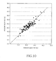
- FIG. 10 is a graph illustrating a correlation between a percent body fat measured by a commercial apparatus and a percent body fat measured by the apparatus 200 for measuring bio-information.
- the X axis represents a standard percent body fat measured by a commercial apparatus (e.g., a Bioelectric Impedance Analysis (BIA) apparatus), and the Y axis represents the percent body fat measured by the apparatus 200 for measuring bio-information.
- a commercial apparatus e.g., a Bioelectric Impedance Analysis (BIA) apparatus
- the Y axis represents the percent body fat measured by the apparatus 200 for measuring bio-information.
- Each percent body fat measured by the apparatus 200 is represented as a small square, and a clinical trial has been conducted with both males and females as targets.
- each measured percent body fat has been computed by using equation (8), the lower abdomen has been measured in the case of every male, and the fleshy inside of the thigh has been measured in the case of every female.
- the third coefficients F P , G P , H P , and I P are given respectively as -14.693, 1.303, 0.067 and 10.833, and in the case of females, the third coefficients F P , G P , H P , and I P are respectively given as -3.009, 1.142, 0.088 and 13.339.
- the standard percent body fat and the percent body fat have a correlation coefficient of about 0.905 therebetween.
- the input device 265 functions as an interface for receiving basic bio-information, including sex distinction, age, height, weight, etc., from a user.
- the input device 256 can be embodied with a keypad conventionally provided to a handheld device, including a wireless mobile terminal and the like.
- the memory 260 stores a table required to express relations between the basic bio-information and the second coefficients necessary to compute the basic bio-information and the thickness of subcutaneous fat. Namely, in the table, the basic bio-information (e.g., data sets expressed as ⁇ sex distinction, age, and measurement positions ⁇ ) and coefficient sets (e.g., data sets represented as ⁇ C P , D P , and E P ⁇ ) corresponding to the basic bio-information are recorded.
- the basic bio-information e.g., data sets expressed as ⁇ sex distinction, age, and measurement positions ⁇
- coefficient sets e.g., data sets represented as ⁇ C P , D P , and E P ⁇
- the controller 250 enables the memory 260 to store the basic bio-information provided from the input device 265, enables the first light sources 220, the second light sources 230 and the third light source 240 to be driven one by one, and computes skin color (i.e., an MI) and the thickness of subcutaneous fat on the basis of the intensities of the first to third detection lights sequentially detected by the photo detector 210 and the table. The controller 250 can then compute the percent body fat.
- skin color i.e., an MI
- the controller 250 can then compute the percent body fat.
- the controller 250 is electrically connected with the photo detector 210, the first light sources 220, the second light sources 230 and the third light source 240, receives an output signal from the photo detector 210, and outputs a driving signal to each of the first light sources 220, the second light sources 230 and the third light source 240.
- the controller 250 substitutes a BMI computed by equation (4) for height and weight among the basic bio-information provided from the input device 265, and enables the substituted BMI to be stored.
- drive order can be optionally determined.
- FIG. 11 is a flowchart illustrating a control process of the controller 250.
- the controller 250 performs the following steps S 1 to S4.
- step S1 the basic bio-information, including sex distinction, age, height, weight, measurement positions, etc., is input from a user by using the input device 265.
- step S2 intensities of the first to the third detection lights are detected.
- the controller 250 enables the first light sources 220, the second light sources 230 and the third light source 240 to be driven in turn, and senses intensities of the first to the third detection lights sequentially detected by the photo detector 210.
- An electrical signal provided from the photo detector 210 has a voltage level depending on the intensity of light input into the photo detector 210.
- the controller 250 can correspond to a digital device which is not equipped with an analog/digital interface, or the photo detector 210, the first light sources 220, the second light sources 220, and the third light source 240 can correspond to analog devices which are not equipped with an analog/digital interface.
- an analog-to-digital converter can be connected between the controller 250 and the photo detector 210, and a digital-to-analog converter can be connected between the controller 250 and each of the first to the third light sources 220, 230, and 240.
- step S3 skin colors equivalent to the intensities of the first and the second detection lights are determined.
- Skin color i.e., an MI
- MI can be computed by substituting the intensities of the first and the second detection lights into equation (1).
- step S4 the thickness of subcutaneous fat is determined on the basis of the basic bio-information, the intensities of the first to the third detection lights, and the values stored in a table as described above.
- the controller 250 determines three coefficients corresponding to the basic bio-information.
- This step can be regarded as a process for mapping the basic bio-information to the three coefficients. Since the table has discrete data sets (i.e., ⁇ sex distinction, age, and measurement positions ⁇ and ⁇ C P , D P , and E P ⁇ ), if the basic bio-information is given, the three coefficients corresponding to the basic bio-information can be determined through an approximation algorithm. For example, basic bio-information which is the most approximate to basic bio-information given in the table is found, or three coefficients which are approximate through interpolation can be computed.
- the controller 250 substitutes the three determined coefficients, the intensities of the first to the third detection lights, and the BMI (or height and weight) into equation (7), and then computes the thickness of subcutaneous fat.
- the controller 250 can display skin color and the thickness of subcutaneous fat.
- the apparatus 200 for measuring bio-information can further include a display device, such as a Liquid Crystal Display (LCD), which is electrically connected with the controller 250.
- LCD Liquid Crystal Display
- the apparatus 200 for measuring bio-information according to the present invention can be applied to a mobile terminal or a wearable device, such as a mobile phone, a Personal Digital Assistant (PDA), etc., and can be modularized so as to form a single body with the mobile terminal or so as to be installable into the mobile terminal.
- the apparatus 200 may include at least one photo detector 210, at least one first light source 220, at least one second light source 230, at least one third light source 240 and a controller 250, and the output of the photo detector 210 is output to a mobile phone by wire, or the output of the photo detector 210 can be output to a mobile terminal ⁇ wirelessly using an antenna.
- the controller 250 performs only the function for enabling the first light sources 220, the second light sources 230 and the third light source 240, and since a mobile terminal is conventionally equipped with a control unit and a memory, the control unit of the mobile terminal can perform steps for computing the above-described skin color and the thickness of subcutaneous fat.
- FIG. 12 is a plane view illustrating an apparatus for measuring bio-information according to a second exemplary embodiment of the present invention
- FIG. 13 is a sectional view taken along line A-A in the apparatus for measuring bio-information. Since the apparatus 300 for measuring bio-information has a configuration and the functions similar to those of the apparatus 200 depicted in FIG. 3 the difference between the apparatus 200 and the apparatus 300 is a larger number of third light sources 240A and a larger number of waveguides. Similar elements will be designated by the same reference numerals, and an overlapping description will be omitted.
- the apparatus 300 for measuring bio-information includes a photo detector 210, multiple first light sources 220, multiple second light sources 230, multiple third light sources 240A, a waveguide 310, a memory 260, an input device 265, and a controller 250.
- the controller 250, the memory 260, and the input device 265 which are depicted in FIG. 13 are not illustrated.
- the photo detector 210 is arranged on the surface of the skin (not shown), and outputs an electrical signal that is converted by photoelectric conversion from an input light.
- the photo detector 210 detects light radiating from the surface of the skin and outputs an electrical signal.
- the first four light sources 220 and the second four light sources 230 are arranged alternately, where the first four light sources 220 and the second four light sources 230 are separate from the photo detector 210 at the same distance, and are arranged at the same intervals in a circumferential direction.
- Each of the four first light sources 220 is arranged on the surface of the skin so as to be separate from the photo detector 210, and radiates a first light having a first wavelength (e.g., 660 nm) in the band of visible light on the surface of the skin.
- a first wavelength e.g., 660 nm
- Each of the four second light sources 230 is arranged on the surface of the skin so as to be separate from the photo detector 210, and radiates a second light having a second wavelength (e.g., 940 nm) in the band of near infrared rays on the surface of the skin.
- a second wavelength e.g. 940 nm
- the waveguide 310 has a shape of a circular ring, is arranged on the surface of the skin so as to surround the photo detector 210 and the first and second light sources 220 and 230, has an inner circumferential surface and an outer circumferential surface opposite each other, and has an upper surface and a lower surface opposite each other. At this time, the lower surface of the waveguide 310 functions as an output end, and can be in tight contact with the surface of the skin or can separate from it.
- a sectional surface perpendicular to a circumferential direction i.e., a direction perpendicular to the direction of a diameter of the waveguide 310) thereof has a square shape.
- the waveguide 310 has a larger refractive index than air or the skin, and light travels in the manner of total reflection in a circumferential direction inside the waveguide 310.
- the waveguide 310 can be implemented by using material, such as polycarbonate, acryl-based resin, etc. that has a transparent characteristics with respect to a wavelength of a third light, and can be manufactured by injection molding or other similar methods. Otherwise, the waveguide 310 can be embodied with rubber material that has a transparent characteristic with respect to the wavelength of the third light, and preferably, can be realized with material such as polyurethane, silicon, and the like.
- the upper surface of the waveguide 310 is equipped with multiple light extracting patterns 320 formed to output light traveling to the inside of the waveguide 310 to the outside of the waveguide 310 through the lower surface thereof.
- Each of the light extracting patterns 320 scatters an incident light.
- the light extracting patterns 320 are formed symmetrically with the center of curvature of the waveguide 310 as the reference. By destroying a total internal reflection condition at a boundary between the waveguide 310 and air or the skin with respect to an incident light, each of the light extracting patterns 320 allows light to transmit through the lower surface of the waveguide 310.
- the part of scattered light transmitted through the lower surface of the waveguide 310 is outputted (radiated) to the outside of the waveguide 310. Also, as both light traveling as it stands without being scattered by the light extracting patterns 320 and the rest of the scattered light satisfy the total reflection condition, the traveling light and the rest of the scattered light continue to travel inside the waveguide 310, and are then incident to different light extracting patterns.
- Each of the light extracting patterns 320 can be either a scratch, concave-convex, a prism pattern, or other similar light diverting patterns, formed by either printing, photolithography, lasing, and/or stamping.
- Each of the light extracting patterns 320 can have solid structures with various shapes, such as a cone, a hemisphere, a hexahedron, a triangular pyramid, a quadrangular pyramid, and so forth, and can be formed in a shape of intaglio or an embossed shape on the upper surface of the waveguide 310.
- desired light extracting patterns are applied to a mold, and the waveguide 310 and the light extracting patterns 320 can be simultaneously formed through injection molding using the mold.
- Each of the light extracting patterns 320 can be provided in a form of Bragg grating, etc., that has a periodic variation of a refractive index, and this kind of variation of a refractive index can be implemented through polling, the irradiation of ultraviolet rays, and the like.
- the light extracting patterns 320 can be formed on the lower surface of the waveguide 310.
- the light extracting patterns 320 is limited to scattering an incident light, other than this the light extracting patterns 320 can be provided in a form of a coating layer, etc., that has a refractive index (e.g., a refractive index similar to a refractive index of the waveguide 310) that destroys a total internal reflection condition.
- a refractive index e.g., a refractive index similar to a refractive index of the waveguide 310 that destroys a total internal reflection condition.
- multiple light extracting patterns are limited to being formed on the upper surface of the waveguide 310,
- the third light sources 240A are symmetrically arranged with the photo detector 210 as the center, and respective output ends of the third light sources 240A face the outer circumferential surface of the waveguide 310.
- Each of the third light sources 240A couples a third light having a second wavelength in the band of near infrared rays to the inside of the waveguide 310.
- the amount of light that transmits a part nearer to the third light sources 240A can be larger than the amount of light that transmits a part which is more distant from the third light sources 240A.
- the density or the size of the light extracting patterns 320 in a position nearer to the third light sources 240A is set to be different from the density or the size of the light extracting patterns 320 in a position which is more distant from the third light sources 240A, and with this, an overall distribution of the amount of light that appears on the lower surface of the waveguide 310 can be adjusted, regardless of a distance from the third light sources 240A.
- the density of light extracting patterns 320 in a relatively near position can be set to be low, and the density of light extracting patterns 320 in a relatively distant position can be set to be progressively higher.
- FIG. 14 is a plane view illustrating an apparatus for measuring bio-information according to a third exemplary embodiment of the present invention
- FIG. 15 is a sectional view taken along line B-B in the apparatus for measuring bio-information.
- the apparatus 400 for measuring bio-information has a configuration and functions similar to that of the apparatus 300 for measuring bio-information depicted in FIG. 12 .
- the difference between the apparatus 300 and the apparatus 400 is a larger number of first and the second light sources 220A and 230A. This allows for more arrangements corresponding to the increased number of the first and the second light sources 220A and 230A than the apparatus 300.
- a second waveguide 410 is included. Similar, elements are designated by the same reference numerals, and an overlapping description will be omitted.
- the apparatus 400 for measuring bio-information includes a photo detector 210, multiple first light sources 220A, multiple second light sources 230A, multiple third light sources 240A, first and the second waveguides 310 and 410, a memory 260, an input device 265, and a controller 250.
- the second waveguide 410 having a shape of a circular ring, is arranged on the surface of the skin so as to surround the photo detector 210 and the first and second light sources 220 and 230.
- the second waveguide 410 has an inner circumferential surface and an outer circumferential surface opposite each other, and has an upper surface and a lower surface opposite each other.
- the lower surface of the second waveguide 410 functions as an output end, and can be tightly contact with the surface of the skin or can be separate from the skin surface.
- a sectional surface perpendicular to a circumferential direction i.e., a direction perpendicular to the direction of a diameter of the second waveguide 410) thereof has a substantially square shape.
- the second waveguide 410 has a larger refractive index than air or the skin, and light travels in the manner of total reflection in a circumferential direction inside the second waveguide 410.
- the second waveguide 410 can be implemented by using the same or similar material as that of first waveguide 310.
- the upper surface of the second waveguide 410 is equipped with multiple light extracting patterns 420 formed to output light traveling to the inside of the second waveguide 410 to the outside of the second waveguide 410 through the lower surface thereof.
- Each of the light extracting patterns 420 scatters an incident light.
- the light extracting patterns 420 are formed symmetrically with the center of curvature of the second waveguide 410 as the reference. By destroying a total internal reflection condition on a boundary surface between the second waveguide 410 and air or the skin with respect to an incident light, each of the light extracting patterns 420 allows light scattered at the light extracting patterns 420 to transmit the lower surface of the second waveguide 410.
- each of the light extracting patterns 420 can have the same shape as that of light extracting patterns 320 formed in the first waveguide 310.
- the first light sources 220A are symmetrically arranged with the photo detector 210 as the center, and respective output ends of the first light sources 220A face the outer circumferential surface of the second waveguide 410.
- the second light sources 230A are symmetrically arranged with the photo detector 210 as the center, and respective output ends of the second light sources 230A face the outer circumferential surface of the second waveguide 410.
- Each of the first light sources 220A couples a first light having a first wavelength to the inside of the second waveguide 410
- each of the second light sources 230A couples a second light having a second wavelength to the inside of the second waveguide 410.
- first light sources 220A are arranged on a first axis
- second light sources 230A can be arranged on a second axis perpendicular to the first axis.
- a pair of light sources may be arranged in the center of the apparatus, and multiple photo detectors can be arranged around the pair of light sources.
- FIG. 16 is a sectional view illustrating an apparatus for measuring bio-information according to a fourth exemplary embodiment of the present invention.
- the apparatus for measuring bio-information 500 has a configuration and function similar to that of apparatus 200 depicted in FIG. 3 .
- Biological tissue 270 has a structure in which respective layers corresponding to muscle 272, subcutaneous fat 274, and skin 276 are laminated in that order.
- the apparatus 200 for measuring bio-information includes a first light source 220B, a second light source 230B, a first photo detector 210A, a second photo detector 210B, a Memory (MEM) 260, an input device 265, and a Controller (CTRL) 250.
- a first light source 220B a second light source 230B
- MEM Memory
- CTRL Controller
- the first light source 220B is arranged on the surface of the skin 276, and radiates a first light having a first wavelength (e.g., 660 nm) in the band of visible light on the surface of the skin 276.
- a first wavelength e.g., 660 nm
- the second light source 230B is arranged on the surface of the skin 276 so as to be in close contact with the first light source 220B, and radiates a second light having a second wavelength (e.g., 880 nm) in the band of near infrared rays on the surface of the skin 276.
- a second wavelength e.g. 880 nm
- the first photo detector 210A is arranged on the surface of the skin 276 so as to be separate from the first and the second light sources 220B and 230B, and outputs an electrical signal which has been converted by photoelectric conversion from an input light
- the second photo detector 210B is arranged on the surface of the skin 276 in such a manner as to be placed in a more distant position from the first and the second light sources 220B and 230B than the first photo detector 210A, and outputs an electrical signal from an input light
- a distance between the first photo detector 210A and the first and second light sources 220B and 230B equals 2 mm
- a distance between the second photo detector 210B and the first and second light sources 220B and 230B equals 10 mm.
- a distance between the first photo detector 210A and the first and second light sources 220B and 230B is equal to or shorter than 5 mm, and a distance between the second photo detector 210B and the first and second light sources 220B and 230B is equal to or longer than 10 mm.
- a light received by the first photo detector 210A among rays of the first light is specifically referred to as a "first detection light”
- a light received by the first photo detector 210A among rays of the second light is specifically referred to as a "second detection light”
- a light received by the second photo detector 210B among rays of the second light is specifically referred to as a "third detection light.”
- the memory 260 stores a table required to express relations between the basic bio-information and the second coefficients necessary to compute the basic bio-information and the thickness of subcutaneous fat.
- the controller 250 enables the first and the second light sources 220B and 230B to be driven one by one, computes the color of the skin 276 on the basis of the intensities of the first and the second detection lights sequentially detected by the first photo detector 210A, and computes skin color (i.e., an MI) and the thickness of subcutaneous fat 274 on the basis of the intensity of the third detection light detected by the second photo detector 210B and the table.
- skin color i.e., an MI
- the controller 250 is electrically connected with the first and second light sources 220B and 230B and the first and second photo detectors 210A and 210B, receives output signals from the first and the second photo detectors 210A and 210B, and outputs a driving signal to each of the first and the second light sources 220B and 230B.
- the first and the second light sources which output lights having wavelengths different from each other are used, lights having wavelengths different from each other can be simultaneously output, or a single light source whose wavelength is variable can be used.
- various pieces of bio-information can be derived by using the first to the third detection lights.
- a wavelength of near infrared rays is used, a pulse wave is measured at the tip of the finger in which capillary vessels aggregate densely, and then, heart rate variability (in other words, stress) can be derived.
- heart rate variability in other words, stress
- oxygen saturation changes in the blood i.e., percent SPO 2
- a waveform of changes of blood flow volume of a peripheral artery i.e., PhotoPlenthysmoGraphy; PPG
- breathing rate per minute, pulse, and the like can also be measured.
- an apparatus for measuring bio-information according to the present invention is different from the prior apparatus for measuring bio-information, in that it not only considers the influence of the skin the prior apparatus for measuring bio-information, but also receives basic biological information from a user, thereby providing a more accurate measurement of the thickness of subcutaneous fat by reflecting the received basic biological information.
- the apparatus for measuring bio-information since a fewer number of light sources can be employed by using a waveguide than in the prior apparatus, it is suitable for a mobile terminal requiring a high economic efficiency.
- the above-described controller according to the present invention can be realized in hardware or as software or computer code that can be stored in a recording medium such as a CD ROM, an RAM, a floppy disk, a hard disk, or a magneto-optical disk or downloaded over a network, so that the methods described herein can be rendered in such software using a general purpose computer, or a special processor or in programmable or dedicated hardware, such as an ASIC or FPGA.
- the computer, the processor or the programmable hardware include memory components, e.g., RAM, ROM, Flash, etc. that may store or receive software or computer code that when accessed and executed by the computer, processor or hardware implement the processing methods described herein.
Abstract
Description
- The present invention relates to an apparatus and a method for measuring bio-information, and more particularly to an apparatus and a method for measuring information about the skin and subcutaneous fat by using light.
- Various methods for measuring body fat or the thickness of subcutaneous fat have been known to the general public. Methods for measuring the thickness of subcutaneous fat include a method for direct measurement using calipers, a method using ultrasonic waves, a method using Computerized Tomography (CT), Magnetic Resonance Imaging (MRI), and the like. The method for directly measuring the thickness of subcutaneous fat using calipers is inaccurate and inconvenient, and causes pain. The method for measuring the thickness of subcutaneous fat by using ultrasonic waves, or CT, or MRI require expensive equipment and experts. Also, since it is inconvenient to measure the thickness of subcutaneous fat because of the need for devices for implementing the previously described methods, research on measurement methods using light have been performed.
- One method for measuring body fat or the thickness of subcutaneous fat by using light corresponds to illuminating light onto the surface of the skin of a living body, and then detecting light radiating from the surface of the skin due to multiple scattering and converting the detected light to an electrical signal. This method has advantages in that it is non-invasive, and has a short measurement time. Also, since an apparatus for implementing this method has a small size, the apparatus has an advantage that it can measure the thickness of subcutaneous fat on occasion.
-
FIG. 1 is a view illustrating an apparatus for measuring the thickness of subcutaneous fat according to the prior art.Biological tissue 130 has a structure in which respective layers corresponding tomuscle 132,subcutaneous fat 134, andskin 136 having a thickness of 0.5 to 4 mm, are laminated in that order, and theskin 136 can be subdivided into a horny layer, the outer skin, and the true skin. Theabove apparatus 100 includes a Light Emitting Diode (LED) 110 and a PhotoDiode or PhotoDetector (PD) 120. TheLED 110 and thePD 120 are separate from each other, and are arranged on the surface of theskin 136. If theLED 110 irradiates light having a wavelength in the band of near infrared on the surface of theskin 136, some light travels in a direction from the surface of theskin 136 to themuscle 132, some of the light is directed to the surface of theskin 136 due to multiple scattering. Most of the light is absorbed by themuscle 132. ThePD 120 detects light radiating from the surface of theskin 136 and converts it to an electrical signal. -
FIG. 2 is a graph illustrating a change in the output of thePD 120 as a function of the thickness of thesubcutaneous fat 134 according to separation distances from theLED 110. The X axis represents the thickness of thesubcutaneous fat 134 in millimeters (mm), and the Y axis represents the output voltage of thePD 120 in Volts (V). Herein, an 'SD' represents a Separation Distance between theLED 110 and thePD 120.FIG. 2 depicts output curves corresponding to cases where SDs equal 5 mm (expressed in a solid line including small squares), 10 mm (expressed in a solid line including small circles), and 20 mm (expressed in a solid line including small triangles), respectively. To examine the output curve relevant to each SD, it can be recognized that the thicker thesubcutaneous fat 134 the more an output of thePD 120 increases toward becoming saturated. Also, it can be determined that the more distant the SD becomes, the wider the range of the thickness of thesubcutaneous fat 134 that can be measured. -
U.S. Patent No. 4,850,365 , entitled "Near Infrared Apparatus and Method for Determining Percent Fat in a Body", invented by Rosenthal et al., discloses technology in which light having a single wavelength is irradiated on the surface of the skin, and then, percent body fat is measured by detecting light radiating from the surface of the skin due to multiple scattering within the subcutaneous fat layer. -
U.S. Patent No. 4,633,087 , entitled "Near Infrared Apparatus for Measurement of Organic Constituents of Material", invented by Rosenthal et al., discloses technology in which multiple rays of light having wavelengths different from one another are irradiated on the surface of the skin, and then, percent body fat is measured by detecting rays of light radiating from the surface of the skin due to multiple scattering within the subcutaneous fat layer. - However, since not only the thickness of subcutaneous fat but also the color and the thickness of the skin affects the output of the PD, the prior technologies of bio-information measurement have problems in that an error in percent body fat caused by the color and the thickness of the skin, or an error in the thickness of subcutaneous fat cannot be effectively corrected.
- The present invention provides an apparatus for measuring bio-information, which can measure bio-information more accurately by using basic bio-information, which is input by a user.
- In accordance with an aspect of the present invention, there is provided an apparatus for measuring bio-information of a user, including: an input device for receiving basic bio-information of the user, a first light source arranged on the surface of the skin for radiating a first light having a first wavelength on the surface of the skin, a second light source arranged on the surface of the skin for radiating a second light having a second wavelength on the surface of the skin; a third light source arranged on the surface of the skin in such a manner as to be placed in a more distant position from a photo detector than the first and the second light sources, and radiating a third light having a third wavelength on the surface of the skin, the photo detector detecting detection lights associated with said first through third lights, all of which transmitted through the surface of the skin and converted to electrical signals and a control unit for enabling the first to the third light sources to be driven in a known order and for producing bio-information of the user on the basis of the basic bio-information and intensities of the first to the third detection lights.
- In accordance with another aspect of the present invention, there is provided an apparatus for measuring bio-information of a user, including an input device for receiving basic bio-information of the user, a first light source arranged on the surface of the skin radiating a first light having a first wavelength onto the surface of the skin, a second light source arranged on the surface of the skin and radiating a second light having a second wavelength onto the surface of the skin, a first photo detector for sequentially detecting a first detection light and a second detection light, which are transmitted through the surface of the skin and converted to electrical signals, a second photo detector for detecting a third detection light, transmitted through the surface of the skin and converted to an electrical signal and a control unit for enabling the first and the second light sources to be driven in an known order and for producing bio-information of the user on the basis of the basic bio-information and intensities of the first to the third detection lights.
- The above and other exemplary features, aspects, and advantages of the present invention will be more apparent from the following detailed description taken in conjunction with the accompanying drawings, in which:
- FIG. 1
- is a view illustrating an apparatus for measuring the thickness of sub- cutaneous fat according to the prior art;
- FIG. 2
- is a graph illustrating a change in the output of the PD as a function of the thickness of the subcutaneous fat according to separation distances from the LED;
- FIG. 3
- is a plane view illustrating an apparatus for measuring bio-information according to a first exemplary embodiment of the present invention;
- FIG. 4
- is a sectional view illustrating the apparatus for measuring bio- information depicted in
FIG. 3 ; - FIG. 5
- is a graph illustrating a correlation between a standard Melanin Index (MI) measured by a commercial apparatus and an MI measured by the apparatus for measuring bio-information depicted in FG. 4;
- FIG. 6
- is a graph illustrating changes of the thickness of the skin correspond- ing to measurement positions;
- FIGs. 7 to 9
- are graphs illustrating correlations between standard thicknesses of subcutaneous fat measured by a commercial apparatus and thicknesses of subcutaneous fat measured by the apparatus for measuring bio- information depicted in FG. 4;
- FIG. 10
- is a graph illustrating a correlation between a percent body fat meas- ured by a commercial apparatus and a percent body fat measured by the apparatus for measuring bio-information;
- FIG. 11
- is a flowchart illustrating a control process of a controller depicted in
FIG. 4 ; - FIG. 12
- is a plane view illustrating an apparatus for measuring bio-information according to a second exemplary embodiment of the present invention;
- FIG. 13
- is a sectional view of the apparatus for measuring bio-information taken along a line A-A in
FIG. 12 ; - FIG. 14
- is a plane view illustrating an apparatus for measuring bio-information according to a third exemplary embodiment of the present invention;
- FIG. 15
- is a sectional view of the apparatus for measuring bio-information taken along a line B-B in
FIG. 14 ; and - FIG. 16
- is a sectional view illustrating an apparatus for measuring bio- information according to a fourth exemplary embodiment of the pre- sent invention.
- Exemplary embodiments of the present invention are described in detail with reference to the accompanying drawings. The description includes particulars, such as specific configuration elements that are provided to facilitate more comprehensive understanding of the present invention, and it will be obvious to those of ordinary skill in the art that prescribed changes in form and modifications may be made to the particulars in the scope of the present invention. Further, in the following description of the present invention, a detailed description of known functions and configurations incorporated herein are omitted when it may make the subject matter of the present invention rather unclear.
-
FIG. 3 is a plane view illustrating an apparatus for measuring bio-information according to a first exemplary embodiment of the present invention, andFIG. 4 is a sectional view illustrating the apparatus for measuring bio-information depicted inFIG. 3 .Biological tissue 270 has a structure in which respective layers corresponding to muscle 272,subcutaneous fat 274, andskin 276 are laminated in that order. Theapparatus 200 for measuring bio-information includes aphoto detector 210, multiple firstlight sources 220, multiple secondlight sources 230, a thirdlight source 240, a Memory (MEM) 260, aninput device 265, and a Controller (CTRL) 250. InFIG. 3 , thecontroller 250, thememory 260, and theinput device 265 all of which are depicted inFIG. 4 are not illustrated. - The
photo detector 210 is arranged on the surface of theskin 276, and outputs an electrical signal converted by photoelectric conversion from an input light. That is, thephoto detector 210 detects input light that is transmitted through the surface of theskin 276 and converts the detected light to an electrical signal. Thephoto detector 210 is equipped with a light receiving surface at the lower end thereof, and the light receiving surface of thephoto detector 210 can tightly contact with the surface of theskin 276, or can be separate from the skin. A conventional photo diode can be used asphoto detector 210. - Around the
photo detector 210, one or more (four '4' as an exemplary embodiment)first light sources 220 and one or more (four '4' as an exemplary embodiment) secondlight sources 230 are arranged alternately, where thefirst light sources 220 and the secondlight sources 230 are separate from thephoto detector 210 by the same distance, and are arranged at the same intervals in a circumferential direction. That is, in a direction perpendicular to the direction of a diameter thereof with thephoto detector 210 as the center. - Each of the
first light sources 220 is arranged on the surface of theskin 276 so as to be separate from thephoto detector 210, and radiates a first light (denoted in a solid line) having a first wavelength (e.g., 660 nm) in a band (desirably, 600 to 750 nm) of visible light on the surface of theskin 276. The firstlight source 220 is equipped with a light emitting surface at the lower end thereof, and the light emitting surface of the firstlight source 220 can tightly contact with the surface of theskin 276, or can be separate from the surface of the skin. As the firstlight source 220, a conventional LED or Laser Diode (LD) can be used. - Each of the second
light sources 230 is arranged on the surface of theskin 276 so as to be separate from thephoto detector 210, and radiates a second light (denoted in a dotted line) having a second wavelength (e.g., 880 nm) in a band (desirably, 750 to 1,000 nm) of near infrared rays on the surface of theskin 276. The secondlight source 230 is equipped with a light emitting surface at the lower end thereof, and the light emitting surface of the secondlight source 230 can tightly contact with the surface of theskin 276, or can be separate from the surface of the skin. As the secondlight source 230, a conventional LED or LD can be used. - The third
light source 240 is arranged on the surface of theskin 276 in such a manner as to be placed in a more distant position fromphoto detector 210 than the first and the secondlight sources skin 276. The thirdlight source 240 is equipped with a light emitting surface at the lower end thereof, and the light emitting surface of the thirdlight source 240 can tightly contact with the surface of theskin 276, or can be separate from the surface of the skin. As the thirdlight source 240, a conventional LED or LD can be used. In the present embodiment, the third wavelength is set so as to be the same as the second wavelength. - Each of the
photo detector 210, thefirst light sources 220 and the secondlight sources 230, and the thirdlight source 240 can be separate from the skin, but in this case, optical coupling efficiency and the accuracy of measurement caused by an alignment error can be reduced. - In the present embodiment, a typical distance between the
photo detector 210 and the first and secondlight sources photo detector 210 and the thirdlight source 240 equals 10 mm. Desirably, a distance between thephoto detector 210 and the first and secondlight sources photo detector 210 and the thirdlight source 240 is equal to or longer than 10 mm. Since the first and the secondlight sources skin 276, in order to reduce the influence depending on the thickness of thesubcutaneous fat 274, it is desirable that the distance between thephoto detector 210 and the first and secondlight sources light source 240 is used to measure information about thesubcutaneous fat layer 274, so that measuring a wide range of the thickness of the subcutaneous fat can be accomplished, it is desirable that the distance between thephoto detector 210 and the thirdlight source 240 is set so as to be equal to or longer than 10 mm. - Collagen fiber included in the
skin 276 has an unsymmetrical optical characteristic. In the present embodiment, while multiple firstlight sources 220 are arranged evenly around thephoto detector 210 in order to offset a directional characteristic of theskin 276, a singlefirst light source 220 can be used. For the same reasons as above, a single secondlight source 230 can be used. - A light received by the
photo detector 210 among the first lights is specifically referred to as a "first detection light", a light received by thephoto detector 210 among the second lights is specifically referred to as a "second detection light", and a light received by thephoto detector 210 among the third light is specifically referred to as a "third detection light." - Skin color is largely influenced by a Melanin Index (MI) and an erythema index. The MI is used to classify a human race, and the erythema index is determined by a distribution of capillary vessels and a distribution of blood existing in the skin. The erythema index is easily affected by pressure applied to the skin, and has such a tendency that variations classified by individuals are largely reduced due to blocking blood if the pressure is strong. Under these conditions, skin color can be represented by using only the MI.
- The MI can be defined by the following equation (1):

where A and B represent first coefficients, - I 1 represents the intensity of the first detection light,
- I 2 represents the intensity of the second detection light; and
- In represents a natural logarithmic function.
- The first coefficients A and B are found through numerical analysis such as a least square method, and at this time, an MI (hereinafter, an MI obtained by a commercial apparatus is referred to as a "standard MI") obtained by a commercial apparatus for diagnosing skin color (e.g., a Mexameter MX18 manufactured by CK Electric company).
- In providing numerical examples accompanied by various algorithms proposed in the present invention, experimental conditions are adopted as a premise.
- As the
first light sources 220, an OPA6611 LED chip that the Knowledge-on company has released is used, having a maximum current value equal to 145 milli-amperes (mA) while being driven with a pulse whose duty cycle is 8 %. As the secondlight sources 230, an OPA8732HP(F) LED chip that the Knowledge-on company has released is used, having a maximum current value equal to 28 mA while being driven with a pulse whose duty cycle is 8 %. As the thirdlight source 240, an OPA8750T LED chip that the Knowledge-on company has released is used, having a maximum current value equal to 290 mA while being driven with a pulse whose duty cycle is 8 %. As thephoto detector 210, an HPI-12N silicon photo diode that the Kodenshi Korea Company has released is used, which has a chip size of 1.2 mm X 1.2 mm. A separation distance between thephoto detector 210 and the first and secondlight sources photo detector 210 and the thirdlight source 240 equals 25 mm. The intensity (i.e., optical power) of each detection light corresponds to the value computed by subtracting an intensity (the intensity of an ambient light, such as natural light, lighting, etc.) measured by thephoto detector 210, in a state where relevant light sources stop operating, from an intensity detected by thephoto detector 210 in a state where relevant light sources operate. A clinical trial has been conducted with adult males in the age range of twenty to fifty and adult females in the age range of twenty to thirty as a target. -
FIG. 5 is a graph illustrating a correlation between a standard Melanin Index (MI) measured by a commercial apparatus and an MI measured by the apparatus, in accordance with the principles of the invention, for measuring bio-information. - In
FIG. 5 , the X axis represents a standard Melanin Index (MI) measured by the commercial apparatus, and the Y axis represents an MI measured by theapparatus 200 for measuring bio-information. Each MI measured by theapparatus 200 is represented as a small square. In the present numerical example 1, a measured MI is computed by using equation (1), and the respective first coefficients A and B are set to '280.14' and '-575.01'. The two melanin indices A and B show a correlation coefficient of about '0.921'. - The intensity of a detection light detected by the
photo detector 210 varies depending on the color and the thickness of theskin 276, and in addition to this, optical characteristics, such as sex, age, height, weight, and the like, that affect the intensity of a detection light. - The Subcutaneous Adipose Tissue (SAT) of the
subcutaneous fat 274 is given as a function of optical characteristics that an intensity I 3 of the third detection light having a wavelength of 880 nm, theskin 276, thesubcutaneous fat 274, and themuscle 272 have, and is defined by the following equation (2):
where GEN represents sex distinction, AGE represents age, HT represents height, WT represents weight, SC represents skin color, and ST represents the thickness of the skin. -
FIG. 6 is a graph illustrating changes of the thickness of the skin corresponding to measurement positions. The thickness of the skin has been measured by using Computerized Tomography (CT), and with 34 Korean females in their twenties as a target, biceps, triceps, upper abdomen, lower abdomen, front thigh, inner thigh, lateral thigh, rear thigh, and calf have been measured. As illustrated, since a variation of the thickness of the skin in each measurement position is not large, in equation (2), it is possible to substitute the thickness of the skin with a measurement position.
where POS denotes a measurement position. - As expressed in equation (4), skin color can be substituted by an MI, and height (HT) and weight (WT) can be represented by using a Body Mass Index (BMI).

and
- In equation (4), if the intensity of the third detection light, the BMI, and the MI are specified as variables and the remaining factors are specified as coefficients, equation (4) can be represented as:

where SATP represents the thickness of subcutaneous fat classified by measurement positions. - Also, equation (5) can be expressed as:

and
- In equation (6), a function fP is specifically expressed as the following equation (7).

- In equation (7), second coefficients CP , DP , and EP can be found through multiple regression analysis in which, with sex distinction, age, and measurement positions specified as constants, a process for substituting SATP measured by CT, IMI measured by the
apparatus 200 and BMI obtained by a user's input into equation (7) is repeated. The multiple regression analysis can also be applied to equation (5). -
FIG. 7 is a graph illustrating a correlation between the standard thickness of subcutaneous fat measured by a commercial apparatus and the thickness of subcutaneous fat measured by theapparatus 200. - In
FIG. 7 , the X axis represents the standard thickness of subcutaneous fat measured by a commercial apparatus (e.g., an ultrasonic apparatus), and the Y axis represents the thickness of subcutaneous fat measured by theapparatus 200. The standard thickness and the thickness of subcutaneous fat have a correlation coefficient of about '0.95' therebetween. The thickness of subcutaneous fat has been measured by using CT, and with 13 Korean females in their twenties as a target, biceps, triceps, upper abdomen, lower abdomen, front thigh, inner thigh, lateral thigh, rear thigh, and calf have been measured. -
FIG. 8 is a graph illustrating a correlation between the standard thickness of subcutaneous fat measured by a commercial apparatus and the thickness of subcutaneous fat measured by theapparatus 200. - In
FIG. 8 , the X axis represents the standard thickness of subcutaneous fat measured by a commercial apparatus, and the Y axis represents the thickness of subcutaneous fat measured by theapparatus 200 in accordance with the principles of the invention. Each thickness of subcutaneous fat measured by theapparatus 200 is represented as a small square, and a clinical trial has been conducted with males as a target. In the present numerical example 2, each measured thickness of subcutaneous fat has been computed by using equation (7), and the second coefficients CP , DP , and EP are given as in TABLE 1, depending on measurement positions. The standard thickness and the thickness of subcutaneous fat have a correlation coefficient of about '0.932' therebetween.TABLE 1 CP DP EP biceps -3.016 0.159 25.705 calf 0.693 0.062 23.506 front thigh -4.756 0.325 22.841 lower abdomen -27.105 1.592 24.771 flank -3.075 0.404 16.865 triceps -2.327 0.180 15.673 -
FIG. 9 is a graph illustrating a correlation between the standard thickness of subcutaneous fat measured by a commercial apparatus and the thickness of subcutaneous fat measured by theapparatus 200. - In
FIG. 9 , the X axis represents the standard thickness of subcutaneous fat measured by a commercial apparatus, and the Y axis represents the thickness of subcutaneous fat measured by theapparatus 200 for measuring bio-information. Each thickness of subcutaneous fat measured by theapparatus 200 for measuring bio-information is represented as a small square, and a clinical trial has been conducted with females as a target. In the present numerical example 3, each measured thickness of subcutaneous fat has been computed by using equation (7), and the second coefficients CP, DP , and EP , depending on measurement positions, are given as in TABLE 2,. The standard thickness and the thickness of subcutaneous fat have a correlation coefficient of about '0.926' therebetween.TABLE 2 CP DP EP Biceps -5.680 0.490 6.989 Calf 2.507 0.155 18.304 front thigh -5.244 0.446 15.410 inner thigh -7.443 0.959 14.074 lower abdomen -20.776 1.709 25.000 Flank -13.463 1.213 6.909 triceps -7.170 0.772 8.265 - A percent body fat can be defined by the following equation (8).

- In equation (8), third coefficients FP, GP, HP , and IP can be found through multiple regression analysis in which, with sex distinction and measurement positions specified as constants, a process for substituting PBFP measured by CT, IMI measured by the
apparatus 200 for measuring bio-information, and both AGE and BMI obtained by a user's input into equation (8) is repeated. -
FIG. 10 is a graph illustrating a correlation between a percent body fat measured by a commercial apparatus and a percent body fat measured by theapparatus 200 for measuring bio-information. - In
FIG. 10 , the X axis represents a standard percent body fat measured by a commercial apparatus (e.g., a Bioelectric Impedance Analysis (BIA) apparatus), and the Y axis represents the percent body fat measured by theapparatus 200 for measuring bio-information. Each percent body fat measured by theapparatus 200 is represented as a small square, and a clinical trial has been conducted with both males and females as targets. In the present numerical example 3, each measured percent body fat has been computed by using equation (8), the lower abdomen has been measured in the case of every male, and the fleshy inside of the thigh has been measured in the case of every female. In the case of males, the third coefficients FP, GP, HP , and IP are given respectively as -14.693, 1.303, 0.067 and 10.833, and in the case of females, the third coefficients FP, GP, HP , and IP are respectively given as -3.009, 1.142, 0.088 and 13.339. The standard percent body fat and the percent body fat have a correlation coefficient of about 0.905 therebetween. - Referring to
FIG. 3 again, theinput device 265 functions as an interface for receiving basic bio-information, including sex distinction, age, height, weight, etc., from a user. For instance, the input device 256 can be embodied with a keypad conventionally provided to a handheld device, including a wireless mobile terminal and the like. - The
memory 260 stores a table required to express relations between the basic bio-information and the second coefficients necessary to compute the basic bio-information and the thickness of subcutaneous fat. Namely, in the table, the basic bio-information (e.g., data sets expressed as {sex distinction, age, and measurement positions}) and coefficient sets (e.g., data sets represented as {CP , DP, and EP }) corresponding to the basic bio-information are recorded. - The
controller 250 enables thememory 260 to store the basic bio-information provided from theinput device 265, enables thefirst light sources 220, the secondlight sources 230 and the thirdlight source 240 to be driven one by one, and computes skin color (i.e., an MI) and the thickness of subcutaneous fat on the basis of the intensities of the first to third detection lights sequentially detected by thephoto detector 210 and the table. Thecontroller 250 can then compute the percent body fat. To this end, thecontroller 250 is electrically connected with thephoto detector 210, thefirst light sources 220, the secondlight sources 230 and the thirdlight source 240, receives an output signal from thephoto detector 210, and outputs a driving signal to each of thefirst light sources 220, the secondlight sources 230 and the thirdlight source 240. Thecontroller 250 substitutes a BMI computed by equation (4) for height and weight among the basic bio-information provided from theinput device 265, and enables the substituted BMI to be stored. - In the present embodiment, while it is exemplified that the
first light sources 220, the secondlight sources 230 and the thirdlight source 240 are driven in turn, drive order can be optionally determined. -
FIG. 11 is a flowchart illustrating a control process of thecontroller 250. Thecontroller 250 performs the following steps S 1 to S4. - In step S1, the basic bio-information, including sex distinction, age, height, weight, measurement positions, etc., is input from a user by using the
input device 265. - In step S2, intensities of the first to the third detection lights are detected. The
controller 250 enables thefirst light sources 220, the secondlight sources 230 and the thirdlight source 240 to be driven in turn, and senses intensities of the first to the third detection lights sequentially detected by thephoto detector 210. An electrical signal provided from thephoto detector 210 has a voltage level depending on the intensity of light input into thephoto detector 210. Thecontroller 250 can correspond to a digital device which is not equipped with an analog/digital interface, or thephoto detector 210, thefirst light sources 220, the secondlight sources 220, and the thirdlight source 240 can correspond to analog devices which are not equipped with an analog/digital interface. In this case, an analog-to-digital converter can be connected between thecontroller 250 and thephoto detector 210, and a digital-to-analog converter can be connected between thecontroller 250 and each of the first to the thirdlight sources - In step S3, skin colors equivalent to the intensities of the first and the second detection lights are determined. Skin color (i.e., an MI) can be computed by substituting the intensities of the first and the second detection lights into equation (1).
- In step S4, the thickness of subcutaneous fat is determined on the basis of the basic bio-information, the intensities of the first to the third detection lights, and the values stored in a table as described above.
- First, the
controller 250 determines three coefficients corresponding to the basic bio-information. This step can be regarded as a process for mapping the basic bio-information to the three coefficients. Since the table has discrete data sets (i.e., {sex distinction, age, and measurement positions} and {CP , DP , and EP }), if the basic bio-information is given, the three coefficients corresponding to the basic bio-information can be determined through an approximation algorithm. For example, basic bio-information which is the most approximate to basic bio-information given in the table is found, or three coefficients which are approximate through interpolation can be computed. - Second, the
controller 250 substitutes the three determined coefficients, the intensities of the first to the third detection lights, and the BMI (or height and weight) into equation (7), and then computes the thickness of subcutaneous fat. - Subsequently, the
controller 250 can display skin color and the thickness of subcutaneous fat. To this end, theapparatus 200 for measuring bio-information can further include a display device, such as a Liquid Crystal Display (LCD), which is electrically connected with thecontroller 250. - The
apparatus 200 for measuring bio-information according to the present invention can be applied to a mobile terminal or a wearable device, such as a mobile phone, a Personal Digital Assistant (PDA), etc., and can be modularized so as to form a single body with the mobile terminal or so as to be installable into the mobile terminal. Theapparatus 200 may include at least onephoto detector 210, at least onefirst light source 220, at least one secondlight source 230, at least one thirdlight source 240 and acontroller 250, and the output of thephoto detector 210 is output to a mobile phone by wire, or the output of thephoto detector 210 can be output to a mobile terminal \ wirelessly using an antenna. In such cases, thecontroller 250 performs only the function for enabling thefirst light sources 220, the secondlight sources 230 and the thirdlight source 240, and since a mobile terminal is conventionally equipped with a control unit and a memory, the control unit of the mobile terminal can perform steps for computing the above-described skin color and the thickness of subcutaneous fat. - When considering a directional characteristic of biological tissue, it is necessary that not only the number of the first and the second
light sources light sources 240 increase in order to surround thephoto detector 210. - However, since a manufacturing cost of the
apparatus 200 for measuring bio-information increases in the above case, in the following embodiments, structures will be proposed in which the number of light sources is minimized by using a waveguide, and simultaneously, errors caused by a directional characteristic of biological tissue can be corrected. -
FIG. 12 is a plane view illustrating an apparatus for measuring bio-information according to a second exemplary embodiment of the present invention, andFIG. 13 is a sectional view taken along line A-A in the apparatus for measuring bio-information. Since theapparatus 300 for measuring bio-information has a configuration and the functions similar to those of theapparatus 200 depicted inFIG. 3 the difference between theapparatus 200 and theapparatus 300 is a larger number of third light sources 240A and a larger number of waveguides. Similar elements will be designated by the same reference numerals, and an overlapping description will be omitted. Theapparatus 300 for measuring bio-information includes aphoto detector 210, multiple firstlight sources 220, multiple secondlight sources 230, multiple third light sources 240A, awaveguide 310, amemory 260, aninput device 265, and acontroller 250. InFIG. 12 , thecontroller 250, thememory 260, and theinput device 265 which are depicted inFIG. 13 are not illustrated. - The
photo detector 210 is arranged on the surface of the skin (not shown), and outputs an electrical signal that is converted by photoelectric conversion from an input light. Thephoto detector 210 detects light radiating from the surface of the skin and outputs an electrical signal. - Positioned around the
photo detector 210, the first fourlight sources 220 and the second fourlight sources 230 are arranged alternately, where the first fourlight sources 220 and the second fourlight sources 230 are separate from thephoto detector 210 at the same distance, and are arranged at the same intervals in a circumferential direction. - Each of the four
first light sources 220 is arranged on the surface of the skin so as to be separate from thephoto detector 210, and radiates a first light having a first wavelength (e.g., 660 nm) in the band of visible light on the surface of the skin. - Each of the four second
light sources 230 is arranged on the surface of the skin so as to be separate from thephoto detector 210, and radiates a second light having a second wavelength (e.g., 940 nm) in the band of near infrared rays on the surface of the skin. - The
waveguide 310 has a shape of a circular ring, is arranged on the surface of the skin so as to surround thephoto detector 210 and the first and secondlight sources waveguide 310 functions as an output end, and can be in tight contact with the surface of the skin or can separate from it. A sectional surface perpendicular to a circumferential direction (i.e., a direction perpendicular to the direction of a diameter of the waveguide 310) thereof has a square shape. Thewaveguide 310 has a larger refractive index than air or the skin, and light travels in the manner of total reflection in a circumferential direction inside thewaveguide 310. Thewaveguide 310 can be implemented by using material, such as polycarbonate, acryl-based resin, etc. that has a transparent characteristics with respect to a wavelength of a third light, and can be manufactured by injection molding or other similar methods. Otherwise, thewaveguide 310 can be embodied with rubber material that has a transparent characteristic with respect to the wavelength of the third light, and preferably, can be realized with material such as polyurethane, silicon, and the like. - The upper surface of the
waveguide 310 is equipped with multiple light extractingpatterns 320 formed to output light traveling to the inside of thewaveguide 310 to the outside of thewaveguide 310 through the lower surface thereof. Each of the light extractingpatterns 320 scatters an incident light. The light extractingpatterns 320 are formed symmetrically with the center of curvature of thewaveguide 310 as the reference. By destroying a total internal reflection condition at a boundary between thewaveguide 310 and air or the skin with respect to an incident light, each of the light extractingpatterns 320 allows light to transmit through the lower surface of thewaveguide 310. Since a part of light scattered to the lower surface of thewaveguide 310 by thelight extracting patterns 320 does not satisfy a total reflection condition (i.e., in a case where an incident angle is smaller than a critical angle), the part of scattered light transmitted through the lower surface of thewaveguide 310, and is outputted (radiated) to the outside of thewaveguide 310. Also, as both light traveling as it stands without being scattered by thelight extracting patterns 320 and the rest of the scattered light satisfy the total reflection condition, the traveling light and the rest of the scattered light continue to travel inside thewaveguide 310, and are then incident to different light extracting patterns. Each of the light extractingpatterns 320 can be either a scratch, concave-convex, a prism pattern, or other similar light diverting patterns, formed by either printing, photolithography, lasing, and/or stamping. Each of the light extractingpatterns 320 can have solid structures with various shapes, such as a cone, a hemisphere, a hexahedron, a triangular pyramid, a quadrangular pyramid, and so forth, and can be formed in a shape of intaglio or an embossed shape on the upper surface of thewaveguide 310. Selectively, desired light extracting patterns are applied to a mold, and thewaveguide 310 and the light extractingpatterns 320 can be simultaneously formed through injection molding using the mold. Each of the light extractingpatterns 320 can be provided in a form of Bragg grating, etc., that has a periodic variation of a refractive index, and this kind of variation of a refractive index can be implemented through polling, the irradiation of ultraviolet rays, and the like. The light extractingpatterns 320 can be formed on the lower surface of thewaveguide 310. In the present embodiment, while thelight extracting patterns 320 is limited to scattering an incident light, other than this the light extractingpatterns 320 can be provided in a form of a coating layer, etc., that has a refractive index (e.g., a refractive index similar to a refractive index of the waveguide 310) that destroys a total internal reflection condition. In the present embodiment, while multiple light extracting patterns are limited to being formed on the upper surface of thewaveguide 310, a single light extracting pattern continuously formed all over the upper surface of thewaveguide 310 can exist. - The third light sources 240A are symmetrically arranged with the
photo detector 210 as the center, and respective output ends of the third light sources 240A face the outer circumferential surface of thewaveguide 310. Each of the third light sources 240A couples a third light having a second wavelength in the band of near infrared rays to the inside of thewaveguide 310. - Since light coupled from each of the third light sources 240A to the inside of the
waveguide 310 attenuates by degrees while traveling in a circumferential direction of thewaveguide 310 in the manner of total reflection, in thewaveguide 310, the amount of light that transmits a part nearer to the third light sources 240A can be larger than the amount of light that transmits a part which is more distant from the third light sources 240A. So as to solve these problems, the density or the size of the light extractingpatterns 320 in a position nearer to the third light sources 240A is set to be different from the density or the size of the light extractingpatterns 320 in a position which is more distant from the third light sources 240A, and with this, an overall distribution of the amount of light that appears on the lower surface of thewaveguide 310 can be adjusted, regardless of a distance from the third light sources 240A. For instance, with the third light sources 240A as the reference, the density of light extractingpatterns 320 in a relatively near position can be set to be low, and the density of light extractingpatterns 320 in a relatively distant position can be set to be progressively higher. -
FIG. 14 is a plane view illustrating an apparatus for measuring bio-information according to a third exemplary embodiment of the present invention, andFIG. 15 is a sectional view taken along line B-B in the apparatus for measuring bio-information. Since theapparatus 400 for measuring bio-information has a configuration and functions similar to that of theapparatus 300 for measuring bio-information depicted inFIG. 12 . The difference between theapparatus 300 and theapparatus 400 is a larger number of first and the second light sources 220A and 230A. This allows for more arrangements corresponding to the increased number of the first and the second light sources 220A and 230A than theapparatus 300. Further, asecond waveguide 410 is included. Similar, elements are designated by the same reference numerals, and an overlapping description will be omitted. Theapparatus 400 for measuring bio-information includes aphoto detector 210, multiple first light sources 220A, multiple second light sources 230A, multiple third light sources 240A, first and thesecond waveguides memory 260, aninput device 265, and acontroller 250. - The
second waveguide 410, having a shape of a circular ring, is arranged on the surface of the skin so as to surround thephoto detector 210 and the first and secondlight sources second waveguide 410 has an inner circumferential surface and an outer circumferential surface opposite each other, and has an upper surface and a lower surface opposite each other. The lower surface of thesecond waveguide 410 functions as an output end, and can be tightly contact with the surface of the skin or can be separate from the skin surface. A sectional surface perpendicular to a circumferential direction (i.e., a direction perpendicular to the direction of a diameter of the second waveguide 410) thereof has a substantially square shape. Thesecond waveguide 410 has a larger refractive index than air or the skin, and light travels in the manner of total reflection in a circumferential direction inside thesecond waveguide 410. Thesecond waveguide 410 can be implemented by using the same or similar material as that offirst waveguide 310. - The upper surface of the
second waveguide 410 is equipped with multiple light extractingpatterns 420 formed to output light traveling to the inside of thesecond waveguide 410 to the outside of thesecond waveguide 410 through the lower surface thereof. Each of the light extractingpatterns 420 scatters an incident light. The light extractingpatterns 420 are formed symmetrically with the center of curvature of thesecond waveguide 410 as the reference. By destroying a total internal reflection condition on a boundary surface between thesecond waveguide 410 and air or the skin with respect to an incident light, each of the light extractingpatterns 420 allows light scattered at the light extractingpatterns 420 to transmit the lower surface of thesecond waveguide 410. Since a part of light scattered to the side of the lower surface of thesecond waveguide 410 by thelight extracting patterns 420 does not satisfy a total reflection condition (i.e., in a case where an incident angle is smaller than a critical angle), the part of scattered light transmits through the lower surface of thesecond waveguide 410, and is thus output outside of thesecond waveguide 410. Also, as both light traveling as it stands without being scattered by thelight extracting patterns 420 and the rest of the scattered light satisfy the total reflection condition, the traveling light and the rest of the scattered light continue to travel inside thesecond waveguide 410, and are then incident to different light extracting patterns. Each of the light extractingpatterns 420 can have the same shape as that of light extractingpatterns 320 formed in thefirst waveguide 310. - The first light sources 220A are symmetrically arranged with the
photo detector 210 as the center, and respective output ends of the first light sources 220A face the outer circumferential surface of thesecond waveguide 410. The second light sources 230A are symmetrically arranged with thephoto detector 210 as the center, and respective output ends of the second light sources 230A face the outer circumferential surface of thesecond waveguide 410. Each of the first light sources 220A couples a first light having a first wavelength to the inside of thesecond waveguide 410, and each of the second light sources 230A couples a second light having a second wavelength to the inside of thesecond waveguide 410. In the present embodiment, while a single first light source 220A and a single second light source 230A contact closely with each other to form a pair, with thephoto detector 210 as the center, the first light sources 220A are arranged on a first axis, and the second light sources 230A can be arranged on a second axis perpendicular to the first axis. - In the above-described embodiments, while a single photo detector is arranged right in the center of the apparatus for measuring bio-information, and multiple light sources are arranged around the photo detector, a pair of light sources may be arranged in the center of the apparatus, and multiple photo detectors can be arranged around the pair of light sources.
-
FIG. 16 is a sectional view illustrating an apparatus for measuring bio-information according to a fourth exemplary embodiment of the present invention. - The apparatus for measuring
bio-information 500 has a configuration and function similar to that ofapparatus 200 depicted inFIG. 3 . The, difference between theapparatus 200 and theapparatus 500 in the arrangements and the number of photo detectors 210A and 210B and the arrangement and the number of first and second light sources 220B and 230B. Therefore, similar elements shown inFigures 3 and12 will be designated by the same reference numerals, and an overlapping description will be omitted. -
Biological tissue 270 has a structure in which respective layers corresponding to muscle 272,subcutaneous fat 274, andskin 276 are laminated in that order. Theapparatus 200 for measuring bio-information includes a first light source 220B, a second light source 230B, a first photo detector 210A, a second photo detector 210B, a Memory (MEM) 260, aninput device 265, and a Controller (CTRL) 250. - The first light source 220B is arranged on the surface of the
skin 276, and radiates a first light having a first wavelength (e.g., 660 nm) in the band of visible light on the surface of theskin 276. - The second light source 230B is arranged on the surface of the
skin 276 so as to be in close contact with the first light source 220B, and radiates a second light having a second wavelength (e.g., 880 nm) in the band of near infrared rays on the surface of theskin 276. - The first photo detector 210A is arranged on the surface of the
skin 276 so as to be separate from the first and the second light sources 220B and 230B, and outputs an electrical signal which has been converted by photoelectric conversion from an input light The second photo detector 210B is arranged on the surface of theskin 276 in such a manner as to be placed in a more distant position from the first and the second light sources 220B and 230B than the first photo detector 210A, and outputs an electrical signal from an input light In the present embodiment, a distance between the first photo detector 210A and the first and second light sources 220B and 230B equals 2 mm, and a distance between the second photo detector 210B and the first and second light sources 220B and 230B equals 10 mm. Desirably, a distance between the first photo detector 210A and the first and second light sources 220B and 230B is equal to or shorter than 5 mm, and a distance between the second photo detector 210B and the first and second light sources 220B and 230B is equal to or longer than 10 mm. - A light received by the first photo detector 210A among rays of the first light is specifically referred to as a "first detection light", a light received by the first photo detector 210A among rays of the second light is specifically referred to as a "second detection light", and a light received by the second photo detector 210B among rays of the second light is specifically referred to as a "third detection light."
- The
memory 260 stores a table required to express relations between the basic bio-information and the second coefficients necessary to compute the basic bio-information and the thickness of subcutaneous fat. - The
controller 250 enables the first and the second light sources 220B and 230B to be driven one by one, computes the color of theskin 276 on the basis of the intensities of the first and the second detection lights sequentially detected by the first photo detector 210A, and computes skin color (i.e., an MI) and the thickness ofsubcutaneous fat 274 on the basis of the intensity of the third detection light detected by the second photo detector 210B and the table. To this end, thecontroller 250 is electrically connected with the first and second light sources 220B and 230B and the first and second photo detectors 210A and 210B, receives output signals from the first and the second photo detectors 210A and 210B, and outputs a driving signal to each of the first and the second light sources 220B and 230B. - In the fourth embodiment of the present invention, while it is exemplified that the first and the second light sources which output lights having wavelengths different from each other are used, lights having wavelengths different from each other can be simultaneously output, or a single light source whose wavelength is variable can be used.
- Also, in the embodiments of the present invention, while it is exemplified that only the color of the skin and the thickness of subcutaneous fat are measured, various pieces of bio-information can be derived by using the first to the third detection lights. For example, because a wavelength of near infrared rays is used, a pulse wave is measured at the tip of the finger in which capillary vessels aggregate densely, and then, heart rate variability (in other words, stress) can be derived. In addition, since a wavelength of near infrared rays and a wavelength of visible light are used simultaneously, oxygen saturation changes in the blood (i.e., percent SPO 2) can also be measured. Besides, a waveform of changes of blood flow volume of a peripheral artery (i.e., PhotoPlenthysmoGraphy; PPG), breathing rate per minute, pulse, and the like can also be measured.
- The merits and effects of exemplary embodiments, as disclosed in the present invention, and as so configured to operate above, will be described as follows.
- As described above, an apparatus for measuring bio-information according to the present invention is different from the prior apparatus for measuring bio-information, in that it not only considers the influence of the skin the prior apparatus for measuring bio-information, but also receives basic biological information from a user, thereby providing a more accurate measurement of the thickness of subcutaneous fat by reflecting the received basic biological information.
- Furthermore, in the apparatus for measuring bio-information according to the present invention, since a fewer number of light sources can be employed by using a waveguide than in the prior apparatus, it is suitable for a mobile terminal requiring a high economic efficiency.
- The above-described controller according to the present invention can be realized in hardware or as software or computer code that can be stored in a recording medium such as a CD ROM, an RAM, a floppy disk, a hard disk, or a magneto-optical disk or downloaded over a network, so that the methods described herein can be rendered in such software using a general purpose computer, or a special processor or in programmable or dedicated hardware, such as an ASIC or FPGA. As would be understood in the art, the computer, the processor or the programmable hardware include memory components, e.g., RAM, ROM, Flash, etc. that may store or receive software or computer code that when accessed and executed by the computer, processor or hardware implement the processing methods described herein.
- While the invention has been shown and described with reference to certain exemplary embodiments thereof, it will be understood by those skilled in the art that various changes in form and details may be made therein without departing from the spirit and scope of the invention. Therefore, the spirit and scope of the present invention must be defined not by described embodiments thereof but by the appended claims and equivalents of the appended claims.
Claims (21)
- An apparatus for measuring bio-information of a user, the apparatus comprising:a device for receiving basic bio-information of the user;a first light source arranged on the surface of the skin radiating a first light having a first wavelength on the surface of the skin;a second light source arranged on the surface of the skin radiating a second light having a second wavelength on the surface of the skin;a third light source arranged on the surface of the skin in such a manner as to be placed in a more distant position from a photo detector than the first and the second light sources, said third light source radiating a third light having a third wavelength on the surface of the skin;the photo detector detecting a first, a second and a third detection light which are transmitted through the surface of the skin and generating corresponding electrical signals, said first, second and third detection light corresponding to said light radiating from said first, second and third light sources; anda control unit for enabling the first to the third light sources to be driven in a known order and for producing bio-information of the user on the basis of the basic bio-information and intensities of the first to the third detection lights.
- The apparatus as claimed in claim 1, wherein the control unit produces a Melanin Index (MI) as:

where A and B represent preset coefficients,I 1 represents the intensity of the first detection light,I 2 represents the intensity of the second detection light andIn represents the natural logarithmic function. - The apparatus as claimed in claim 1, wherein the control unit computes the thickness of subcutaneous fat as:


and
where SATP represents the thickness of subcutaneous fat,CP, DP and EP represent preset coefficients,I 1 represents the intensity of the first detection light,I 2 represents the intensity of the second detection light,I 3 represents the intensity of the third detection light,WT represents a weight of the user, andHT represents a height of the user. - The apparatus as claimed in claim 1, wherein the control unit computes the percent body fat as:


and
where PBFP represents the percent body fat,FP, GP, HP and IP represent preset coefficients,I 1 represents the intensity of the first detection light,I 2 represents the intensity of the second detection light,I 3 represents the intensity of the third detection light,WT represents a weight of the user,HT represents a height of the user, and AGE represents an age of the user. - The apparatus as claimed in claim 1, wherein the first wavelength belongs to a band of visible light, and the second and the third wavelengths belong to a band of near infrared rays.
- The apparatus as claimed in claim 1, further comprising:a waveguide arranged on the surface of the skin so as to be positioned between the first and second light sources and the third light source, enabling the third light provided from the third light source to travel by total reflection within said waveguide; andat least one light extracting pattern for directing the third light outside of the waveguide.
- The apparatus as claimed in claim 6, wherein the waveguide has a shape of a circular ring, and is equipped with a lower surface facing the surface of the skin and an upper surface opposite the lower surface, and the light extracting pattern is formed on the upper surface of the waveguide.
- The apparatus as claimed in claim 1, further comprising:a waveguide positioned between the photo detector and the first and second light sources, enabling the first or the second light provided from the first or the second light source to travel by total reflection within the waveguide; andat least one light extracting pattern for directing the first or the second light outside the waveguide.
- The apparatus as claimed in claim 8, wherein the waveguide has a shape of a circular ring, and is equipped with a lower surface facing the surface of the skin and an upper surface opposite the lower surface, and the light extracting pattern is formed on the upper surface of the waveguide.
- An apparatus for measuring bio-information of a user, the apparatus comprising:a device for receiving basic bio-information of the user;at least one first light source radiating a first light having a first wavelength on the surface of the skin;at least one second light source radiating a second light having a second wavelength on the surface of the skin;a first photo detector for detecting a first detection light and a second detection light transmitted through the surface of the skin and converting said first and second detection light into electrical signals, wherein said first detection light corresponds to said light radiating from said first light source and said second detection light corresponds to a part of the light radiating from said second light source;a second photo detector for detecting a third detection light transmitted through the surface of the skin and converting said third detection light into an electrical signal, said third detection light corresponding to another part of the light radiating from said second light source; anda control unit for enabling the first and the second light sources to be driven in a known order and for producing bio-information of the user on the basis of the basic bio-information and intensities of the first to the third detection lights.
- The apparatus as claimed in claim 10, wherein the control unit produces a Melanin Index (MI) as:

where A and B represent preset coefficients,I 1 represents the intensity of the first detection light, andI 2 represents the intensity of the second light. - The apparatus as claimed in claim 10, wherein the control unit computes the thickness of subcutaneous fat as:


and
where SATP represents the thickness of subcutaneous fat,CP , DP and EP represent preset coefficients,I 1 represents the intensity of the first detection light,I 2 represents the intensity of the second detection light,I 3 represents the intensity of the third detection light,WT represents a weight of the user, andHT represents a height of the user. - The apparatus as claimed in claim 10, wherein the control unit computes the percent body fat as:


and
Cwhere PBFP represents the percent body fat,FP, GP, HP and IP represent preset coefficients-,I 1 represents the intensity of the first detection light,I 2 represents the intensity of the second detection light,I 3 represents the intensity of the third detection light,WT represents a weight of the user,HT represents a height of the user, andAGE represents an age of the user. - The apparatus as claimed in claim 10, wherein the first wavelength belongs to a band of visible light, and the second wavelength belongs to a band of near infrared rays.
- The apparatus of claim 3, further comprising:a memory for storing a table required to express relations between the basic bio-information and coefficients necessary to compute a thickness of subcutaneous fat.
- The apparatus as claimed in claim 4, further comprising:a memory for storing a table required to express relations between the basic bio-information and coefficients necessary to compute a percent body fat.
- The apparatus as claimed in claim 12, further comprising:a memory for storing a table required to express relations between the basic bio-information and coefficients necessary to compute a thickness of subcutaneous fat.
- The apparatus as claimed in claim 13, further comprising:a memory for storing a table required to express relations between the basic bio-information and coefficients necessary to compute a percent body fat.
- The apparatus as claimed in claim 1, wherein said photo detector comprises:a first photo-detector for detecting said first and second detection light; anda second photo-detector for detecting said third detection light.
- The apparatus as claimed in claim 1, wherein said first and second light sources are alternatively arranged around said photo detector.
- The apparatus as claimed in claim 20, wherein said first and second light sources are separated from said photo detector by no more than 5 millimeters.
Applications Claiming Priority (1)
| Application Number | Priority Date | Filing Date | Title |
|---|---|---|---|
| KR1020070072233A KR100905571B1 (en) | 2007-07-19 | 2007-07-19 | Apparatus for measuring living body information |
Publications (3)
| Publication Number | Publication Date |
|---|---|
| EP2016890A2 true EP2016890A2 (en) | 2009-01-21 |
| EP2016890A3 EP2016890A3 (en) | 2009-03-11 |
| EP2016890B1 EP2016890B1 (en) | 2012-12-05 |
Family
ID=39864931
Family Applications (1)
| Application Number | Title | Priority Date | Filing Date |
|---|---|---|---|
| EP08006065A Expired - Fee Related EP2016890B1 (en) | 2007-07-19 | 2008-03-28 | Apparatus for measuring bio-information |
Country Status (4)
| Country | Link |
|---|---|
| US (1) | US8131347B2 (en) |
| EP (1) | EP2016890B1 (en) |
| KR (1) | KR100905571B1 (en) |
| CN (1) | CN101347328B (en) |
Cited By (3)
| Publication number | Priority date | Publication date | Assignee | Title |
|---|---|---|---|---|
| FR2984721A1 (en) * | 2011-12-26 | 2013-06-28 | Chanel Parfums Beaute | METHOD AND DEVICE FOR DETECTION AND QUANTIFICATION OF SKIN SIGNS ON A SKIN AREA |
| EP2839778A1 (en) * | 2013-08-22 | 2015-02-25 | Seiko Epson Corporation | Pulse wave measuring apparatus |
| US11662309B2 (en) | 2014-01-07 | 2023-05-30 | Opsolution Gmbh | Device and method for determining a concentration in a sample |
Families Citing this family (30)
| Publication number | Priority date | Publication date | Assignee | Title |
|---|---|---|---|---|
| JP5789199B2 (en) | 2009-02-25 | 2015-10-07 | ヴァレンセル,インコーポレイテッド | Headset and earbud |
| US8788002B2 (en) | 2009-02-25 | 2014-07-22 | Valencell, Inc. | Light-guiding devices and monitoring devices incorporating same |
| EP2292141B1 (en) * | 2009-09-03 | 2015-06-17 | The Swatch Group Research and Development Ltd | Method and device for taking a patient's pulse using light waves with two wavelengths |
| JP5921543B2 (en) * | 2010-07-22 | 2016-05-24 | 株式会社アモーレパシフィックAmorepacific Corporation | Apparatus and method for measuring skin structure |
| JP5744557B2 (en) * | 2011-02-10 | 2015-07-08 | キヤノン株式会社 | Acoustic wave acquisition device |
| US20140039309A1 (en) * | 2012-04-26 | 2014-02-06 | Evena Medical, Inc. | Vein imaging systems and methods |
| US9029780B2 (en) * | 2013-09-11 | 2015-05-12 | Google Technology Holdings LLC | Electronic device with gesture detection system and methods for using the gesture detection system |
| USD763939S1 (en) | 2014-04-02 | 2016-08-16 | Cephalogics, LLC | Optical sensor array liner with optical sensor array pad |
| USD763938S1 (en) | 2014-04-02 | 2016-08-16 | Cephalogics, LLC | Optical sensor array |
| WO2015197385A1 (en) * | 2014-06-27 | 2015-12-30 | Koninklijke Philips N.V. | Animal vital sign detection system |
| CN106797672B (en) * | 2014-10-02 | 2020-08-04 | Lg 电子株式会社 | Mobile terminal and control method thereof |
| WO2016050486A1 (en) * | 2014-10-02 | 2016-04-07 | Koninklijke Philips N.V. | Optical vital signs sensor. |
| US10531820B2 (en) * | 2014-11-24 | 2020-01-14 | Koninklijke Philips N.V. | Device, system and method for determining the concentration of a substance in the blood of a subject |
| KR101596195B1 (en) | 2015-02-05 | 2016-02-29 | 경희대학교 산학협력단 | Artificial skin sensor and bioinformation diagnostic apparatus based on artificial skin sensor |
| US9752925B2 (en) * | 2015-02-13 | 2017-09-05 | Taiwan Biophotonic Corporation | Optical sensor |
| US10890761B2 (en) | 2015-04-24 | 2021-01-12 | University-Industry Cooperation Group Of Kyung Hee University | Photoreactive sensor including optical amplification phototransistor, and display panel and vehicle control system including photoreactive sensor |
| KR101687490B1 (en) | 2015-06-29 | 2016-12-16 | 경희대학교 산학협력단 | System and method for controlling vehicle |
| WO2018049412A1 (en) | 2016-09-12 | 2018-03-15 | Graftworx, Inc. | Wearable device with multimodal diagnostics |
| CN106551678A (en) * | 2016-11-15 | 2017-04-05 | 上海斐讯数据通信技术有限公司 | A kind of method of intelligent wearable device and measurement body fat rate |
| WO2018134298A1 (en) * | 2017-01-18 | 2018-07-26 | Koninklijke Philips N.V. | Detecting erythema caused by wearable devices |
| JP6847788B2 (en) * | 2017-03-08 | 2021-03-24 | 京セラ株式会社 | Measuring device and measuring method |
| CN110868920B (en) * | 2017-03-29 | 2023-01-03 | 艾利欧公司 | Wearable device with multi-modal diagnostics |
| EP3384829A1 (en) * | 2017-04-05 | 2018-10-10 | Koninklijke Philips N.V. | Skin gloss measurement for quantitative estimation of skin gloss |
| KR102010487B1 (en) * | 2017-07-25 | 2019-08-13 | 피에스아이플러스 주식회사 | Skin diagnosis apparatus |
| WO2019055520A1 (en) | 2017-09-13 | 2019-03-21 | Graftworx, Inc. | Systems and methods for detecting a periprosthetic infection |
| JP7175598B2 (en) * | 2017-10-06 | 2022-11-21 | 浜松ホトニクス株式会社 | fat measuring device |
| KR102500765B1 (en) * | 2017-11-22 | 2023-02-17 | 삼성전자주식회사 | Spectrometer, method for controlling output-gain of spectrometer, apparatus and method for measuring bio-information |
| CN108742515A (en) * | 2018-03-20 | 2018-11-06 | 浙江工业大学 | A kind of method and system measuring body fat based on mobile terminal |
| JPWO2022153781A1 (en) * | 2021-01-18 | 2022-07-21 | ||
| CN113349767B (en) * | 2021-05-26 | 2024-02-23 | 北京麦邦光电仪器有限公司 | Detection probe, electronic device and blood component detection method |
Citations (5)
| Publication number | Priority date | Publication date | Assignee | Title |
|---|---|---|---|---|
| US4633087A (en) | 1985-04-24 | 1986-12-30 | Trebor Industries, Inc. | Near infrared apparatus for measurement of organic constituents of material |
| EP0516251A2 (en) | 1991-04-26 | 1992-12-02 | Reinhard Dr. Möller | Device to detect the thickness of a layer of fat |
| WO1996027325A1 (en) | 1995-03-03 | 1996-09-12 | Huch Albert W | Device for measuring oxygen saturation in the blood present in the body |
| EP1627599A2 (en) | 2004-08-20 | 2006-02-22 | Matsushita Electric Industrial Co., Ltd. | Biological information arithmetic apparatus, biological information arithmetic method, program, and recording medium |
| US20060056661A1 (en) | 2001-06-13 | 2006-03-16 | Hans Einighammer | Method and device for recognition of natural skin |
Family Cites Families (15)
| Publication number | Priority date | Publication date | Assignee | Title |
|---|---|---|---|---|
| US4850365A (en) * | 1988-03-14 | 1989-07-25 | Futrex, Inc. | Near infrared apparatus and method for determining percent fat in a body |
| US5419321A (en) * | 1990-05-17 | 1995-05-30 | Johnson & Johnson Professional Products Limited | Non-invasive medical sensor |
| US6725072B2 (en) * | 1990-10-06 | 2004-04-20 | Hema Metrics, Inc. | Sensor for transcutaneous measurement of vascular access blood flow |
| US5149321A (en) * | 1990-10-10 | 1992-09-22 | Klatz Ronald M | Brain resuscitation device and method for performing the same |
| JP2601766Y2 (en) * | 1992-08-31 | 1999-12-06 | 日本電産コパル株式会社 | Surface emitting device |
| US5485838A (en) * | 1992-12-07 | 1996-01-23 | Nihon Kohden Corporation | Non-invasive blood pressure measurement device |
| JP3365227B2 (en) * | 1996-10-25 | 2003-01-08 | 花王株式会社 | Method and apparatus for measuring optical properties of skin surface condition |
| US6870616B2 (en) * | 1998-06-30 | 2005-03-22 | Jjl Technologies Llc | Spectrometer apparatus for determining an optical characteristic of an object or material having one or more sensors for determining a physical position or non-color property |
| US6353226B1 (en) * | 1998-11-23 | 2002-03-05 | Abbott Laboratories | Non-invasive sensor capable of determining optical parameters in a sample having multiple layers |
| EP1269917A4 (en) * | 2000-04-05 | 2007-03-14 | Matsushita Electric Ind Co Ltd | Biological information measuring instrument and biological information measuring method |
| CN100443048C (en) * | 2003-02-18 | 2008-12-17 | 松下电工株式会社 | Visceral fat measuring instrument, visceral fat measuring method, program, and recording medium |
| KR100571811B1 (en) * | 2003-05-09 | 2006-04-17 | 삼성전자주식회사 | Ear type measurement apparatus for bio signal |
| US7720527B2 (en) * | 2003-11-14 | 2010-05-18 | Panasonic Corp. | Subcutaneous fat thickness measuring method, subcutaneous fat thickness measuring apparatus, program and recording medium |
| KR200381369Y1 (en) | 2005-01-22 | 2005-04-11 | (주)장자건설 | the blocking-plate off the Asphalt-concrete in the Asphalt-finisher |
| JP2007007267A (en) | 2005-07-01 | 2007-01-18 | Kanazawa Univ | Bone density measuring equipment |
-
2007
- 2007-07-19 KR KR1020070072233A patent/KR100905571B1/en active IP Right Grant
-
2008
- 2008-03-28 EP EP08006065A patent/EP2016890B1/en not_active Expired - Fee Related
- 2008-04-17 US US12/148,202 patent/US8131347B2/en not_active Expired - Fee Related
- 2008-07-21 CN CN2008101281736A patent/CN101347328B/en not_active Expired - Fee Related
Patent Citations (5)
| Publication number | Priority date | Publication date | Assignee | Title |
|---|---|---|---|---|
| US4633087A (en) | 1985-04-24 | 1986-12-30 | Trebor Industries, Inc. | Near infrared apparatus for measurement of organic constituents of material |
| EP0516251A2 (en) | 1991-04-26 | 1992-12-02 | Reinhard Dr. Möller | Device to detect the thickness of a layer of fat |
| WO1996027325A1 (en) | 1995-03-03 | 1996-09-12 | Huch Albert W | Device for measuring oxygen saturation in the blood present in the body |
| US20060056661A1 (en) | 2001-06-13 | 2006-03-16 | Hans Einighammer | Method and device for recognition of natural skin |
| EP1627599A2 (en) | 2004-08-20 | 2006-02-22 | Matsushita Electric Industrial Co., Ltd. | Biological information arithmetic apparatus, biological information arithmetic method, program, and recording medium |
Cited By (6)
| Publication number | Priority date | Publication date | Assignee | Title |
|---|---|---|---|---|
| FR2984721A1 (en) * | 2011-12-26 | 2013-06-28 | Chanel Parfums Beaute | METHOD AND DEVICE FOR DETECTION AND QUANTIFICATION OF SKIN SIGNS ON A SKIN AREA |
| WO2013098512A1 (en) * | 2011-12-26 | 2013-07-04 | Chanel Parfums Beaute | Method and device for detecting and quantifying cutaneous signs on an area of skin |
| EP2839778A1 (en) * | 2013-08-22 | 2015-02-25 | Seiko Epson Corporation | Pulse wave measuring apparatus |
| US9560971B2 (en) | 2013-08-22 | 2017-02-07 | Seiko Epson Corporation | Physiological information measuring apparatus |
| US9788727B2 (en) | 2013-08-22 | 2017-10-17 | Seiko Epson Corporation | Physiological information measuring apparatus |
| US11662309B2 (en) | 2014-01-07 | 2023-05-30 | Opsolution Gmbh | Device and method for determining a concentration in a sample |
Also Published As
| Publication number | Publication date |
|---|---|
| EP2016890B1 (en) | 2012-12-05 |
| KR20090008893A (en) | 2009-01-22 |
| CN101347328B (en) | 2011-12-28 |
| US20090024041A1 (en) | 2009-01-22 |
| EP2016890A3 (en) | 2009-03-11 |
| US8131347B2 (en) | 2012-03-06 |
| CN101347328A (en) | 2009-01-21 |
| KR100905571B1 (en) | 2009-07-02 |
Similar Documents
| Publication | Publication Date | Title |
|---|---|---|
| EP2016890B1 (en) | Apparatus for measuring bio-information | |
| EP1886624B1 (en) | Living body measurement apparatus | |
| CN108471950B (en) | System, device and method for monitoring blood oxygen saturation of transcarotomy fetus | |
| US10537270B2 (en) | Method and device for optical measurement of biological properties | |
| US10524705B2 (en) | Tissue oximetry probe with tissue marking feature | |
| US9095291B2 (en) | Spectroscopic sensors | |
| US6801799B2 (en) | Pulse oximeter and method of operation | |
| KR101954548B1 (en) | Diagnostic measuring device | |
| US8406865B2 (en) | Bioimpedance system and sensor and technique for using the same | |
| KR100770833B1 (en) | Optical sensor module | |
| KR102033914B1 (en) | method for measuring blood glucose and wearable type apparatus for the same | |
| WO2019223796A1 (en) | A device for measuring blood pressure | |
| WO2008029978A1 (en) | Non-invasive measuring apparatus of subcutaneous fat thickness and method thereof | |
| KR102223689B1 (en) | Apparatus for measuring bio-information | |
| KR102348195B1 (en) | Optical Analyte Monitering System and Method | |
| Huang et al. | The image analysis of skin tissue irradiated with difference wavelengths of LED sources | |
| WO2021250681A1 (en) | Sensor device to mitigate the effects of unwanted signals made in optical measurements of biological properties | |
| CN113100731A (en) | Blood pressure monitoring device and method | |
| CN213551774U (en) | Biological characteristic detection device and intelligent wearable equipment | |
| KR102290329B1 (en) | Smart biological measurement system | |
| JP2022547131A (en) | Method and apparatus for near-infrared spectroscopy | |
| KR20090038530A (en) | Scanning type device for measuring thickness of subcutaneous fat |
Legal Events
| Date | Code | Title | Description |
|---|---|---|---|
| PUAI | Public reference made under article 153(3) epc to a published international application that has entered the european phase |
Free format text: ORIGINAL CODE: 0009012 |
|
| 17P | Request for examination filed |
Effective date: 20080328 |
|
| AK | Designated contracting states |
Kind code of ref document: A2 Designated state(s): AT BE BG CH CY CZ DE DK EE ES FI FR GB GR HR HU IE IS IT LI LT LU LV MC MT NL NO PL PT RO SE SI SK TR |
|
| AX | Request for extension of the european patent |
Extension state: AL BA MK RS |
|
| PUAL | Search report despatched |
Free format text: ORIGINAL CODE: 0009013 |
|
| AK | Designated contracting states |
Kind code of ref document: A3 Designated state(s): AT BE BG CH CY CZ DE DK EE ES FI FR GB GR HR HU IE IS IT LI LT LU LV MC MT NL NO PL PT RO SE SI SK TR |
|
| AX | Request for extension of the european patent |
Extension state: AL BA MK RS |
|
| 17Q | First examination report despatched |
Effective date: 20090925 |
|
| AKX | Designation fees paid |
Designated state(s): DE GB NL |
|
| GRAP | Despatch of communication of intention to grant a patent |
Free format text: ORIGINAL CODE: EPIDOSNIGR1 |
|
| RAP1 | Party data changed (applicant data changed or rights of an application transferred) |
Owner name: SAMSUNG ELECTRONICS CO., LTD. |
|
| RAP1 | Party data changed (applicant data changed or rights of an application transferred) |
Owner name: SAMSUNG ELECTRONICS CO., LTD. |
|
| GRAS | Grant fee paid |
Free format text: ORIGINAL CODE: EPIDOSNIGR3 |
|
| GRAA | (expected) grant |
Free format text: ORIGINAL CODE: 0009210 |
|
| AK | Designated contracting states |
Kind code of ref document: B1 Designated state(s): DE GB NL |
|
| REG | Reference to a national code |
Ref country code: GB Ref legal event code: FG4D |
|
| REG | Reference to a national code |
Ref country code: DE Ref legal event code: R096 Ref document number: 602008020533 Country of ref document: DE Effective date: 20130131 |
|
| REG | Reference to a national code |
Ref country code: NL Ref legal event code: T3 |
|
| PLBE | No opposition filed within time limit |
Free format text: ORIGINAL CODE: 0009261 |
|
| STAA | Information on the status of an ep patent application or granted ep patent |
Free format text: STATUS: NO OPPOSITION FILED WITHIN TIME LIMIT |
|
| 26N | No opposition filed |
Effective date: 20130906 |
|
| REG | Reference to a national code |
Ref country code: DE Ref legal event code: R097 Ref document number: 602008020533 Country of ref document: DE Effective date: 20130906 |
|
| PGFP | Annual fee paid to national office [announced via postgrant information from national office to epo] |
Ref country code: NL Payment date: 20210209 Year of fee payment: 14 |
|
| PGFP | Annual fee paid to national office [announced via postgrant information from national office to epo] |
Ref country code: GB Payment date: 20210216 Year of fee payment: 14 Ref country code: DE Payment date: 20210208 Year of fee payment: 14 |
|
| REG | Reference to a national code |
Ref country code: DE Ref legal event code: R119 Ref document number: 602008020533 Country of ref document: DE |
|
| REG | Reference to a national code |
Ref country code: NL Ref legal event code: MM Effective date: 20220401 |
|
| GBPC | Gb: european patent ceased through non-payment of renewal fee |
Effective date: 20220328 |
|
| PG25 | Lapsed in a contracting state [announced via postgrant information from national office to epo] |
Ref country code: NL Free format text: LAPSE BECAUSE OF NON-PAYMENT OF DUE FEES Effective date: 20220401 Ref country code: GB Free format text: LAPSE BECAUSE OF NON-PAYMENT OF DUE FEES Effective date: 20220328 Ref country code: DE Free format text: LAPSE BECAUSE OF NON-PAYMENT OF DUE FEES Effective date: 20221001 |