EP2015573A1 - Telecomunication device and system - Google Patents
Telecomunication device and system Download PDFInfo
- Publication number
- EP2015573A1 EP2015573A1 EP07301232A EP07301232A EP2015573A1 EP 2015573 A1 EP2015573 A1 EP 2015573A1 EP 07301232 A EP07301232 A EP 07301232A EP 07301232 A EP07301232 A EP 07301232A EP 2015573 A1 EP2015573 A1 EP 2015573A1
- Authority
- EP
- European Patent Office
- Prior art keywords
- image
- flows
- flow
- compressed data
- operable
- Prior art date
- Legal status (The legal status is an assumption and is not a legal conclusion. Google has not performed a legal analysis and makes no representation as to the accuracy of the status listed.)
- Withdrawn
Links
- 238000000034 method Methods 0.000 claims abstract description 19
- 238000004891 communication Methods 0.000 claims abstract description 17
- 230000008569 process Effects 0.000 claims abstract description 9
- 230000006837 decompression Effects 0.000 claims abstract description 8
- 238000009877 rendering Methods 0.000 claims description 16
- 238000005070 sampling Methods 0.000 claims description 7
- 230000004931 aggregating effect Effects 0.000 claims 2
- 238000007906 compression Methods 0.000 description 14
- 230000006835 compression Effects 0.000 description 11
- 238000012545 processing Methods 0.000 description 8
- 238000005516 engineering process Methods 0.000 description 6
- 230000004888 barrier function Effects 0.000 description 5
- 230000006870 function Effects 0.000 description 5
- 230000005540 biological transmission Effects 0.000 description 4
- 230000002776 aggregation Effects 0.000 description 2
- 238000004220 aggregation Methods 0.000 description 2
- 238000003491 array Methods 0.000 description 2
- 238000006243 chemical reaction Methods 0.000 description 2
- 238000001914 filtration Methods 0.000 description 2
- 230000010354 integration Effects 0.000 description 2
- 230000006978 adaptation Effects 0.000 description 1
- 238000012937 correction Methods 0.000 description 1
- 230000003247 decreasing effect Effects 0.000 description 1
- 230000000694 effects Effects 0.000 description 1
- 230000006872 improvement Effects 0.000 description 1
- 230000004048 modification Effects 0.000 description 1
- 238000012986 modification Methods 0.000 description 1
- 238000011002 quantification Methods 0.000 description 1
- 230000001360 synchronised effect Effects 0.000 description 1
- 230000000007 visual effect Effects 0.000 description 1
Images



Classifications
-
- H—ELECTRICITY
- H04—ELECTRIC COMMUNICATION TECHNIQUE
- H04N—PICTORIAL COMMUNICATION, e.g. TELEVISION
- H04N7/00—Television systems
- H04N7/14—Systems for two-way working
- H04N7/141—Systems for two-way working between two video terminals, e.g. videophone
- H04N7/142—Constructional details of the terminal equipment, e.g. arrangements of the camera and the display
-
- H—ELECTRICITY
- H04—ELECTRIC COMMUNICATION TECHNIQUE
- H04N—PICTORIAL COMMUNICATION, e.g. TELEVISION
- H04N13/00—Stereoscopic video systems; Multi-view video systems; Details thereof
- H04N13/20—Image signal generators
-
- H—ELECTRICITY
- H04—ELECTRIC COMMUNICATION TECHNIQUE
- H04N—PICTORIAL COMMUNICATION, e.g. TELEVISION
- H04N13/00—Stereoscopic video systems; Multi-view video systems; Details thereof
- H04N13/10—Processing, recording or transmission of stereoscopic or multi-view image signals
Definitions
- the present invention relates in general to an end-to-end telecommunication system operable to enable 3D video telephony or 3D video conferencing between mobile user equipments.
- Telecommunication networks provide a facility for communicating to and from a user equipment (UE) using video telephony, i.e. audio visual communication between or among UEs.
- UE user equipment
- 3D video displays such as for instance 3D stereoscopic displays, are available to perform 3D video.
- 3D video is currently not supported for mobile UEs with the existing telecommunication infrastructures, notably due to bandwidth and interoperability limitations as mobile UEs, such as e.g. mobile phone, portable media player or tablet PC, are limited resource devices (LRD) with relatively small CPUs.
- LPD resource devices
- upgrading the architecture components as well as the images formats would cause major investments for telecommunication operators.
- the invention proposes a telecommunication device which is arranged for transmitting data flows comprising 3D video data, said telecommunication system comprising:
- a hardware layer is used to add the required extra data processing capacities.
- This hardware layer may be e.g. a DSP (Digital Signal Processors), VLSI (Very Large Scale Integration Scale), ASIC (Application Specific Integrated Circuits) etc...
- the invention also proposes a telecommunication system for transmitting data flows comprising 3D video data, said telecommunication system comprising:
- the system by avoiding 3D display specific tasks before the compression of the data and by including the compression process of the data into the hardware layer, enables an efficient compression scheme allowing thus transmission on the telecommunication network.
- the invention also relates to a method for transmitting data flows comprising 3D video data from a telecommunication device over a telecommunication network.
- a first mobile user equipment comprises cameras to capture 3D images, compress associated video signals and transmit the resulting data flow, using a video telephony or a video conferencing application, to a second mobile user equipment or more.
- This second UE receives and decompresses the resulting data flow, then builds and displays a 3D image.
- the first UE is called hereafter the emitting UE while the second UE is called the receiving UE.
- Sub-systems of the emitting and the receiving UEs are called unit or layer.
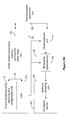
- a telecommunication system is shown to comprise a video input unit 10, a computing unit 20 and a communication application unit 30.
- Video input unit 10, computing unit 20, communication application unit 30 may be found in an emitting UE.
- the video input unit 10 is shown to generate at least two image flows, each delivered by a video camera.
- An alternative embodiment may be to use a video camera and a prism to generate two or more image flows.
- the man skilled in the art may think of other means of generating image flows.
- the video input unit 10 will be illustrated (but not limited to) as generating two image flows for simplification purposes.
- the computing unit 20 is shown to comprise at least one CPU (Central Processing Unit) 23, at least one chip 21 and other board components 25 such as for instance memory, connectivity, other additional chips etc...
- the CPU 23 is the mobile UE CPU in charge of running the mobile UE applications.
- the chip 21, driven by the CPU 23, is in charge of the capture, the processing and the compression of image flows.
- the functions carried out by chip 21 will be further described in relation to Figure 5 later on.
- the additional chips in the board components 25 may be used to have extra data processing capacities when needed.
- the chips may be e.g. DSP (Digital Signal Processors), VLSI (Very Large Scale Integration Scale), ASIC (Application Specific Integrated Circuits) etc...
- the communication application 30 is a software-based video telephony application running on the CPU 23.
- Video telephony may be understood as point to point video telephony as well as video conferencing (point to multipoint). It can be based on any video telephony application like, for instance, the ones based on the H.323 or SIP protocols.
- the communication application 30 exists on both the emitting UE and the receiving UE, and is used to exchange data over the telecommunication network.
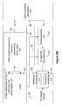
- a telecommunication system is shown to comprise a video output unit 40, a rendering unit 50 and a display unit 60.
- video output unit 40, rendering unit 50 and display unit 60 may be found on a receiving UE.
- the video output unit 40 is shown to comprise the decompression unit 41 and the 3D specific application(s) 43.
- the 3D specific application 43 builds the output 3D image from the decompressed data flow received from the decompression unit 41.
- the rendering unit 50 is the unit in charge of displaying the image on the 3D screen 60.
- the rendering unit may be a software rendering unit 50.
- the display unit 60 is composed of at least one of a 3D screen based on a hardware layer.
- a 3D image is obtained using at least N, where N is at least two, video cameras 12, thus outputting the same number N of image flows.
- a capture and compression process is needed to obtain a single data flow.
- Said capture and compression are realised by the unit 20 using the chip 21 which comprises a hardware layer.
- Chip 21 uses e.g. one, or a combination of, DSP, VLSI, FPGA or ASIC chip(s) dedicated to image processing and integrated in the processing unit 20.
- the data flow obtained by the compression process is thus communicated through the communication application 30, between the emitting UE and the receiving UE, to the video output unit 40.
- the communication application 30 is known by the skilled man as a video telephony application.
- the compressed data flow comprising data associated with the N image flows is processed by the decompression unit 41 resulting in obtaining N image flows.
- the 3D specific application 43 sets up the adjustments which are function of the geometry of the capture and compression unit 14 and the display unit 60, for instance to set up the parallax between the different images, realized the cropping of the images etc...
- This 3D specific application 43 is software based to be easily upgradeable.
- the software rendering unit 50 is a software based application which adapts the image flow received from the video output unit 40 to the display unit 60.
- the software rendering unit 50 sends a left image to the left and a right image to the right ; if the display unit 60 is a barrier auto stereoscopic display unit, the software rendering unit 50 sends an interlaced image etc...
- the adaptation of the image flows to the display unit 60 of the receiving UE cannot be done before the transmission of the single data flow through the network as the output display is not necessarily known from the emitting UE.
- the emitting UE adapts the image flows to a given type of display unit of a receiving UE, but communicates with another receiving UE having another type of display unit, the latter receiving UE is not able to construct a 3D image without a significant loss of resolution.
- 3D video requires sub-sampling of the image flows in order to adapt said image flows to a 3D display device.
- Sub-sampling consists in selecting and keeping a certain amount of pixels according to a pre-defined pattern, taking into account in particular the technology of the 3D display device.
- non compliant screens from different UEs exchanging data flows
- the resulting resolution would hence be the smaller of the two.
- the method according to the invention allows interoperability by avoiding this 3D display device specific sub-sampling on the emitting UE before transmission of the data flow.
- the receiving UE is hence in charge of the sub-sampling through its rendering system 50.
- FIG. 2B an alternative embodiment of the telecommunication system according to the invention is shown. This embodiment uses the different elements described in relation to Figure 2A except for the rendering unit 50.
- the rendering unit is composed of a software rendering unit 50 and of a hardware rendering unit 50'.
- the hardware rendering unit 50' includes at least one hardware component and is linked to the display unit 60. Both software rendering unit 50 and hardware rendering unit 50' operatively coupled fulfil the same function as the software rendering unit 50 of Figure 2A .
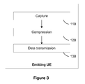
- a first step 110 the emitting UE proceeds first to the capture of image flows from several video cameras.
- a first step 120 the emitting UE proceeds to the compression of resulting data flow.
- a final step 130 the emitting UE proceeds with the transmission of the compressed data flow to the receiving UE using the communication application 30.
- a first step 140 the receiving UE proceeds first to the reception of the compressed data flow using the communication application 30.
- the receiving UE proceeds to the decompression of the received compressed data flow.
- the receiving UE constructs a 3D image from the decompressed data.
- the receiving UE proceeds to the display of the resulting 3D image picture.
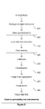
- a series of operations may be carried out by the computing unit 20 and include:
- Figure 6 shows a 3-camera capture system where each camera's resolution is 800 x 600.
- Said embodiment including a description of how the capture and compression parameters may be sent in messages exchanged using the videotelephony application, said parameters comprising:
Landscapes
- Engineering & Computer Science (AREA)
- Multimedia (AREA)
- Signal Processing (AREA)
- Testing, Inspecting, Measuring Of Stereoscopic Televisions And Televisions (AREA)
Abstract
The invention proposes a telecommunication system for transmitting data flows comprising 3D video data, said telecommunication system comprising a 3D video acquiring unit for acquiring a plurality of image flows from different viewpoints; a hardware element operable to process and compress the plurality of image flows into one compressed data flow, said compressed data flow comprising 3D video data for a subsequent 3D image flow generation; a transmitting element operable to communicate the compressed data flow over a communication network; a receiving unit for receiving the compressed data flow; a decompression unit operable to decompress the compressed data flow into a plurality of image flows, said plurality of image flows comprising 3D video data; a 3D application layer operable to process the plurality of image flows into 3D image flows; and a 3D display unit operable to display the 3D image flow.
Description
- The present invention relates in general to an end-to-end telecommunication system operable to enable 3D video telephony or 3D video conferencing between mobile user equipments.
- Telecommunication networks provide a facility for communicating to and from a user equipment (UE) using video telephony, i.e. audio visual communication between or among UEs. Besides, 3D video displays, such as for
instance 3D stereoscopic displays, are available to perform 3D video. Furthermore, 3D video is currently not supported for mobile UEs with the existing telecommunication infrastructures, notably due to bandwidth and interoperability limitations as mobile UEs, such as e.g. mobile phone, portable media player or tablet PC, are limited resource devices (LRD) with relatively small CPUs. In addition, upgrading the architecture components as well as the images formats would cause major investments for telecommunication operators. - Today there is a need for a 3D video solution that can be easily implemented on the existing telecommunication infrastructures.
- It is an object of the present system to overcome disadvantages and/or make improvement over the prior art.
- To that extend, the invention proposes a telecommunication device which is arranged for transmitting data flows comprising 3D video data, said telecommunication system comprising:
- a 3D video acquiring unit for acquiring a plurality of image flows from different viewpoints,
- a hardware element operable to process and compress the plurality of image flows into one compressed data flow, said compressed data flow comprising 3D video data for a subsequent 3D image flow generation,
- a transmitting element operable to communicate the compressed data flow over a communication network.
- Processing and compression of image flows imply high computing capacities. Mobile user equipments, or telecommunications devices, are, by definition, limited resources devices and have, thus, computing capacities and bandwidth limitations. In the device according to the invention, a hardware layer is used to add the required extra data processing capacities. This hardware layer may be e.g. a DSP (Digital Signal Processors), VLSI (Very Large Scale Integration Scale), ASIC (Application Specific Integrated Circuits) etc...
- The invention also proposes a telecommunication system for transmitting data flows comprising 3D video data, said telecommunication system comprising:
- a 3D video acquiring unit for acquiring a plurality of image flows from different viewpoints,
- a hardware element operable to process and compress the plurality of image flows into one compressed data flow, said compressed data flow comprising 3D video data for a subsequent 3D image flow generation,
- a transmitting element operable to communicate the compressed data flow over a communication network,
- a receiving unit for receiving the compressed data flow,
- a decompression unit operable to decompress the compressed data flow into a plurality of image flows, said plurality of image flows comprising 3D video data,
- a 3D application layer operable to process the plurality of image flows into 3D image flows,
- a 3D display unit operable to display the 3D image flow.
- Furthermore, interoperability between the different components of the system is assured since the transmitted data flow is independent of the display unit of the receiving mobile UE. This is achieved while keeping a satisfactory quality of the images. The system, by avoiding 3D display specific tasks before the compression of the data and by including the compression process of the data into the hardware layer, enables an efficient compression scheme allowing thus transmission on the telecommunication network.
- The invention also relates to a method for transmitting data flows comprising 3D video data from a telecommunication device over a telecommunication network.
- Embodiments of the present invention will now be described by way of example only with reference to the accompanying drawings, where like parts are provided with corresponding reference numerals, and in which:
-
Figure 1 schematically illustrates a 3D video mobile telecommunication emitter according to an embodiment of the present invention; -
Figure 2A schematically illustrates a 3D video mobile telecommunication receiver according to an embodiment of the present invention where the rendering unit is software based; -
Figure 2B schematically illustrates a 3D video mobile telecommunication receiver according to an embodiment of the present invention where the rendering unit is software and hardware based; -
Figure 3 schematically illustrates the functions of the 3D video mobile telecommunication emitting UE; -
Figure 4 schematically illustrates the functions of the 3D video mobile telecommunication receiving UE; -
Figure 5 schematically illustrates the capture and compression unit of the 3D video mobile telecommunication system; -
Figure 6 schematically illustrates a 3-camera capture system where each camera's resolution is 800x600. - In the system according to the invention, a first mobile user equipment comprises cameras to capture 3D images, compress associated video signals and transmit the resulting data flow, using a video telephony or a video conferencing application, to a second mobile user equipment or more. This second UE receives and decompresses the resulting data flow, then builds and displays a 3D image. The first UE is called hereafter the emitting UE while the second UE is called the receiving UE. Sub-systems of the emitting and the receiving UEs are called unit or layer.
- Referring to
Figure 1 , a telecommunication system is shown to comprise avideo input unit 10, acomputing unit 20 and acommunication application unit 30.Video input unit 10,computing unit 20,communication application unit 30 may be found in an emitting UE. - The
video input unit 10 is shown to generate at least two image flows, each delivered by a video camera. An alternative embodiment may be to use a video camera and a prism to generate two or more image flows. The man skilled in the art may think of other means of generating image flows. In the hereafter description, thevideo input unit 10 will be illustrated (but not limited to) as generating two image flows for simplification purposes. - The
computing unit 20 is shown to comprise at least one CPU (Central Processing Unit) 23, at least onechip 21 andother board components 25 such as for instance memory, connectivity, other additional chips etc... TheCPU 23 is the mobile UE CPU in charge of running the mobile UE applications. Thechip 21, driven by theCPU 23, is in charge of the capture, the processing and the compression of image flows. The functions carried out bychip 21 will be further described in relation toFigure 5 later on. The additional chips in theboard components 25 may be used to have extra data processing capacities when needed. The chips may be e.g. DSP (Digital Signal Processors), VLSI (Very Large Scale Integration Scale), ASIC (Application Specific Integrated Circuits) etc... - The
communication application 30 is a software-based video telephony application running on theCPU 23. Video telephony may be understood as point to point video telephony as well as video conferencing (point to multipoint). It can be based on any video telephony application like, for instance, the ones based on the H.323 or SIP protocols. Thecommunication application 30 exists on both the emitting UE and the receiving UE, and is used to exchange data over the telecommunication network. - Referring to
Figure 2A , a telecommunication system is shown to comprise avideo output unit 40, arendering unit 50 and adisplay unit 60. Whereascommunication application 30,video output unit 40, renderingunit 50 anddisplay unit 60 may be found on a receiving UE. - The
video output unit 40 is shown to comprise thedecompression unit 41 and the 3D specific application(s) 43. The 3Dspecific application 43 builds theoutput 3D image from the decompressed data flow received from thedecompression unit 41. - The
rendering unit 50 is the unit in charge of displaying the image on the3D screen 60. The rendering unit may be asoftware rendering unit 50. Thedisplay unit 60 is composed of at least one of a 3D screen based on a hardware layer. - A 3D image is obtained using at least N, where N is at least two, video cameras 12, thus outputting the same number N of image flows. In order to transmit these image flows using compatible 2D transport means, a capture and compression process is needed to obtain a single data flow. Said capture and compression are realised by the
unit 20 using thechip 21 which comprises a hardware layer.Chip 21 uses e.g. one, or a combination of, DSP, VLSI, FPGA or ASIC chip(s) dedicated to image processing and integrated in theprocessing unit 20. The data flow obtained by the compression process is thus communicated through thecommunication application 30, between the emitting UE and the receiving UE, to thevideo output unit 40. Thecommunication application 30 is known by the skilled man as a video telephony application. - The compressed data flow comprising data associated with the N image flows is processed by the
decompression unit 41 resulting in obtaining N image flows. The 3Dspecific application 43 sets up the adjustments which are function of the geometry of the capture and compression unit 14 and thedisplay unit 60, for instance to set up the parallax between the different images, realized the cropping of the images etc... This 3Dspecific application 43 is software based to be easily upgradeable. Thesoftware rendering unit 50 is a software based application which adapts the image flow received from thevideo output unit 40 to thedisplay unit 60. For instance, if thedisplay unit 60 is a polarized projector, thesoftware rendering unit 50 sends a left image to the left and a right image to the right ; if thedisplay unit 60 is a barrier auto stereoscopic display unit, thesoftware rendering unit 50 sends an interlaced image etc... - In order to be inter-operable with any 3D display of the receiving UE, the adaptation of the image flows to the
display unit 60 of the receiving UE cannot be done before the transmission of the single data flow through the network as the output display is not necessarily known from the emitting UE. When the emitting UE adapts the image flows to a given type of display unit of a receiving UE, but communicates with another receiving UE having another type of display unit, the latter receiving UE is not able to construct a 3D image without a significant loss of resolution. - Indeed, 3D video requires sub-sampling of the image flows in order to adapt said image flows to a 3D display device. Sub-sampling consists in selecting and keeping a certain amount of pixels according to a pre-defined pattern, taking into account in particular the technology of the 3D display device. Thus, non compliant screens (from different UEs exchanging data flows) having different sub-sampling schemes, are therefore strongly non interoperable. Were such UEs involved in 3D video telephony, the resulting resolution would hence be the smaller of the two. The method according to the invention, allows interoperability by avoiding this 3D display device specific sub-sampling on the emitting UE before transmission of the data flow. The receiving UE is hence in charge of the sub-sampling through its
rendering system 50. - Referring to
Figure 2B , an alternative embodiment of the telecommunication system according to the invention is shown. This embodiment uses the different elements described in relation toFigure 2A except for therendering unit 50. - The 3D display makers may provide rendering tools in the hardware layer. Therefore, in such a case, there is the driver (software layer) which is driving the hardware rendering components. In this alternative embodiment, the rendering unit is composed of a
software rendering unit 50 and of a hardware rendering unit 50'. The hardware rendering unit 50' includes at least one hardware component and is linked to thedisplay unit 60. Bothsoftware rendering unit 50 and hardware rendering unit 50' operatively coupled fulfil the same function as thesoftware rendering unit 50 ofFigure 2A . - Referring to
Figure 3 , actions successively performed by the emitting UE are described. In afirst step 110, the emitting UE proceeds first to the capture of image flows from several video cameras. In afirst step 120, the emitting UE proceeds to the compression of resulting data flow. Eventually, in afinal step 130, the emitting UE proceeds with the transmission of the compressed data flow to the receiving UE using thecommunication application 30. - Referring to
Figure 4 , actions successively performed by the receiving UE are described. In afirst step 140, the receiving UE proceeds first to the reception of the compressed data flow using thecommunication application 30. In afurther step 150, the receiving UE proceeds to the decompression of the received compressed data flow. In afurther step 160, the receiving UE constructs a 3D image from the decompressed data. In afinal step 170, the receiving UE proceeds to the display of the resulting 3D image picture. - Referring to
Figure 5 , in order to capture, process and compress image flows, a series of operations may be carried out by thecomputing unit 20 and include: - analogue-to-
digital conversion 210 if needed: analogue to digital conversion may involve an anti aliasing filter component, a sampling step, a quantification step, but also other filtering steps; -
video synchronisation 220 if needed: the synchronization means that an ADC clock is common to all the camera so that the captured images are synchronized; - lens distortion correction 230: lenses are not perfect systems, therefore it leads to image distortion, especially on the image borders (e.g. Gauss conditions are no more true). The solution is to filter the captured image in order to flatten the image;
- face tracking 240 if wanted: usual videophony systems often track the user's head in order to optimize the different steps to its position. It is also sensitive in the 3D world: since there is an optimal distance called zero parallax plane;
-
calibration 250 if needed: calibration is the compensation of all the differences between each camera (light, axis, angles, etc.) by a filtering; -
parallelization 260 if needed: parallelization may be included in axis calibration ofstep 250; -
aggregation 270 of the N processed image flows into a single data flow by any usual method known of the man skilled in the art: aggregation may be useful in order to transmit a single image flow made from N processed image flows instead of transmitting said N image flows. Indeed, by doing that, there is no need of any new protocol or new multi-image flow API (Application Protocol Interface) to transmit the N image flows. Known API for transmitting one image flow may be re-used. Furthermore, by doing this, compression is more efficient in order to convert the resulting aggregated image flow into a single data flow as image flows are not mixed. There are several different methods to aggregate N image flows such as e.g. concatenation, frequency interlacing, etc... For example, a way of proceeding is to concatenate the N input image flows (generated by the different cameras) in order to create a larger image flow. Each larger image comprises the images taken from the different image flows at the same instant, concatenated into one single image. The input image flows may further be transformed by reducing the quantity of information, without decreasing significantly the quality of the images, using processing techniques commonly known by the man skilled in the art, in order to subsequently concatenate said image flows into one image. -
compression 280 allows reducing the size of the aggregated image flow by obtaining a single data flow consuming less bandwidth on the telecommunication network. - Some if not all of the operations may be carried out by
chip 21 ofFigure 1 . - As an example to describe a further embodiment of the system according to the invention,
Figure 6 shows a 3-camera capture system where each camera's resolution is 800 x 600. Said embodiment including a description of how the capture and compression parameters may be sent in messages exchanged using the videotelephony application, said parameters comprising: - for the capturing unit:
- ➢ An integer which is the number of cameras,
- ➢ Three float arrays (one for each x, y and z coordinates) which are the coordinates of each camera in a referential. The array size is the number of cameras. Since the 3D effect depends only of the camera relative position the center of the referential is not so important. It would be better that the origin is at the center of the capturing unit or at one camera position,
- ➢ An integer couple which is the resolution of the cameras like [800, 600]
- ➢ Number of cameras: 3
- ➢ x coordinates: [0, 0, 0]
- ➢ y coordinates: [-L, 0, L]
- ➢ z coordinates: [0, 0, 0]
- ➢ Resolution: [800,600]
- for the encoding part:
- ➢ An integer giving the encoding method.
- 0 when all the captured pictures are stuck in a big picture without modification.
- 1 when all the captured pictures are stuck in a big picture after cropping the unnecessary information. The cropping is done with respect to the display information.
- 2 when all the captured pictured have been sub sampled (giving the display technology) and stuck in a big picture (without interlacing).
- 3 when all the captured pictured have been sub sampled and interlaced. The interlacing is done with respect to the display information.
- 4 when a depth map has been computed.
- Etc.
- ➢ If the previous field was 0 or 1, we need to know how the pictures have been stuck. Therefore, we also need to transmit two integer arrays which are the x and y coordinates of each picture in the final picture. For instance ([1, 1, 1], [1, 2, 3]) means that the 3 captured pictures are stuck vertically. Another example is ([1, 1, 2, 2,], [1, 2, 1, 2]) means that the 4 captured pictures are stuck as a square.
- ➢ An integer giving the encoding method.
- for the display unit:
- ➢ An integer array representing the 3D technology. The list is [a, b, c, d]
- a is the 3D technology.
- ◆ 0 for no 3D technology.
- ◆ 1 for vertical parallax barrier.
- ◆ 2 for horizontal parallax barrier.
- ◆ 3 for step barrier (diagonal parallax barrier).
- ◆ 4 for horizontal lenticular lens.
- ◆ 5 for vertical lenticular lens.
- ◆ 6 for diagonal lenticular lens.
- ◆ 7 for multi projectors (real projectors, eye wear, and so on).
- b, c and d are the geometrical parameters of the 3D technology
- ◆ If a=1, a=2, a=4 or a=5, b is the number of views and c=0 and d=0 (unused parameters).
- ◆ If a=3 or a=6, b is the number of views and c and d are the x and y parameters of the diagonal mesh.
- ◆ If a=7, b is the number of projectors and c=0 and d=0 (unused parameters).
- a is the 3D technology.
- ➢ An integer couple representing the screen size (in mm). It might be unused in the case of projectors.
- ➢ An integer couple representing the screen resolution.
- ➢ An integer array representing the 3D technology. The list is [a, b, c, d]
Claims (13)
- A telecommunication device for transmitting data flows comprising 3D video data, said telecommunication system comprising:- a 3D video acquiring unit (10) for acquiring a plurality of image flows from different viewpoints,- a hardware element (21) operable to process and compress the plurality of image flows into one compressed data flow, said compressed data flow comprising 3D video data for a subsequent 3D image flow generation,- a transmitting element (30) operable to communicate the compressed data flow over a communication network.
- A telecommunication device according to claim 1 wherein the hardware layer (21) comprises at least one of a DSP, FPGA, ASIC or VLSI.
- A telecommunication device according to one of the claims 1 and 2 wherein the hardware element (21) is further operable to generate a flow of single images from the plurality of image flows by aggregating images taken at the same instant from each image flow into one single image,.
- A telecommunication device according to claim 3, wherein the hardware element (21) is further operable to concatenate the images taken at the same instant from each image flow into one single image.
- A telecommunication device according to any of the preceding claims, wherein the communicated compressed data flow is communicated for subsequent display on a 3D display device and wherein the compressed data flow is deprived of said 3D display data.
- A telecommunication system for transmitting data flows comprising 3D video data, said telecommunication system comprising:- a 3D video acquiring unit (10) for acquiring a plurality of image flows from different viewpoints,- a hardware element (21) operable to process and compress the plurality of image flows into one compressed data flow, said compressed data flow comprising 3D video data for a subsequent 3D image flow generation,- a transmitting element (30) operable to communicate the compressed data flow over a communication network,- a receiving unit (40) for receiving the compressed data flow,- a decompression unit (41) operable to decompress the compressed data flow into a plurality of image flows, said plurality of image flows comprising 3D video data,- a 3D application layer (43) operable to process the plurality of image flows into 3D image flows,- a 3D display unit (50, 60) operable to display the 3D image flow.
- A telecommunication system according to claim 6 wherein the hardware layer (21) comprises at least one of a DSP, FPGA, ASIC or VLSI.
- A telecommunication system according to one of the claims 6 and 7 wherein the hardware element (21) is further operable to concatenate into one single image the images taken from a plurality of image flow at the same instant.
- A telecommunication system according to any of the preceding claims 6 to 8, wherein the display unit comprised a rendering unit (50) and a 3D display device (60), said rendering unit being operable to adapt and display the 3D image flows onto said 3D display device (60) using sub-sampling of said 3D image flows.
- A telecommunication system according to any of the preceding claims 6 to 9, wherein the 3D video acquiring unit (10), the hardware layer (21) and the transmitting element (30) are comprised in an emitting device, while the receiving unit (40), the decompression unit (41), the 3D application layer (43) and the 3D display unit (50, 60) are comprised in a receiving device.
- A method for transmitting data flows comprising 3D video data from a telecommunication device attached to a communication network, said method comprising the steps of:- acquiring a plurality of image flows from different viewpoints,- compressing the plurality of image flows into one compressed data flow using a hardware element (21), said compressed data flow comprising 3D video data for a subsequent 3D image flow generation,- transmitting the compressed data flow over the communication network.
- The method according to claim 11, wherein the compressing step further comprises the step of generating a flow of single images from the plurality of image flows by aggregating images taken at the same instant from each image flow into one single image,.
- The method according to claim 12, wherein the compressing step further comprises the step of concatenating the images taken at the same instant from each image flow into one single image.
Priority Applications (2)
| Application Number | Priority Date | Filing Date | Title |
|---|---|---|---|
| EP07301232A EP2015573A1 (en) | 2007-07-12 | 2007-07-12 | Telecomunication device and system |
| PCT/EP2008/059140 WO2009007458A1 (en) | 2007-07-12 | 2008-07-11 | Telecommunication device and system |
Applications Claiming Priority (1)
| Application Number | Priority Date | Filing Date | Title |
|---|---|---|---|
| EP07301232A EP2015573A1 (en) | 2007-07-12 | 2007-07-12 | Telecomunication device and system |
Publications (1)
| Publication Number | Publication Date |
|---|---|
| EP2015573A1 true EP2015573A1 (en) | 2009-01-14 |
Family
ID=38740502
Family Applications (1)
| Application Number | Title | Priority Date | Filing Date |
|---|---|---|---|
| EP07301232A Withdrawn EP2015573A1 (en) | 2007-07-12 | 2007-07-12 | Telecomunication device and system |
Country Status (2)
| Country | Link |
|---|---|
| EP (1) | EP2015573A1 (en) |
| WO (1) | WO2009007458A1 (en) |
Families Citing this family (1)
| Publication number | Priority date | Publication date | Assignee | Title |
|---|---|---|---|---|
| CN118827823B (en) * | 2023-08-24 | 2025-12-19 | 聚好看科技股份有限公司 | 3D data transmission method and terminal equipment |
Citations (1)
| Publication number | Priority date | Publication date | Assignee | Title |
|---|---|---|---|---|
| WO2003030535A1 (en) * | 2001-10-04 | 2003-04-10 | National Research Council Of Canada | Method and system for stereo videoconferencing |
Family Cites Families (1)
| Publication number | Priority date | Publication date | Assignee | Title |
|---|---|---|---|---|
| US20060238545A1 (en) * | 2005-02-17 | 2006-10-26 | Bakin Dmitry V | High-resolution autostereoscopic display and method for displaying three-dimensional images |
-
2007
- 2007-07-12 EP EP07301232A patent/EP2015573A1/en not_active Withdrawn
-
2008
- 2008-07-11 WO PCT/EP2008/059140 patent/WO2009007458A1/en not_active Ceased
Patent Citations (1)
| Publication number | Priority date | Publication date | Assignee | Title |
|---|---|---|---|---|
| WO2003030535A1 (en) * | 2001-10-04 | 2003-04-10 | National Research Council Of Canada | Method and system for stereo videoconferencing |
Non-Patent Citations (1)
| Title |
|---|
| "3D-VIDEOKONFERENZ", FUNKSCHAU, WEKA FACHZEITSCHRIFTEN VERLAG, POING, DE, vol. 68, no. 8, 29 March 1996 (1996-03-29), pages 67 - 69, XP000591288, ISSN: 0016-2841 * |
Also Published As
| Publication number | Publication date |
|---|---|
| WO2009007458A1 (en) | 2009-01-15 |
Similar Documents
| Publication | Publication Date | Title |
|---|---|---|
| CN111246197B (en) | Three-dimensional video communication method and system, electronic device, server and readable storage medium | |
| US20100238264A1 (en) | Three dimensional video communication terminal, system, and method | |
| EP2136602A1 (en) | Communication terminal and information system | |
| TW201637438A (en) | Timestamp-based audio and video processing method and system thereof | |
| KR20080080591A (en) | Method and apparatus for wireless stereo video streaming | |
| CN113076383B (en) | Road data acquisition vehicle and data acquisition system thereof | |
| CN110865782A (en) | Data transmission method, device and equipment | |
| EP2401736A2 (en) | System and method for displaying multiple images/videos on a single display | |
| CN105049912A (en) | Processing method of video signals and electronic equipment | |
| CN107592452B (en) | Panoramic audio and video acquisition device and method | |
| US20180376181A1 (en) | Networked video communication applicable to gigabit ethernet | |
| US20120007951A1 (en) | System and format for encoding data and three-dimensional rendering | |
| CN115022652A (en) | Cloud-edge-end-collaborative video processing method and system | |
| CN102036090B (en) | Television signal conversion device for digital television terminal | |
| CN109495707B (en) | A high-speed video capture and transmission method | |
| CN102843566B (en) | Communication method and equipment for three-dimensional (3D) video data | |
| EP2015573A1 (en) | Telecomunication device and system | |
| US8599240B2 (en) | Super-resolution from 3D (3D to 2D conversion) for high quality 2D playback | |
| GB2526618A (en) | Method for generating a screenshot of an image to be displayed by a multi-display system | |
| US20210344890A1 (en) | Video display apparatus and video processing apparatus | |
| EP2709367A2 (en) | Image processing apparatus and camera module using the same | |
| CN101340546A (en) | High Resolution Video Conferencing System | |
| KR20020015219A (en) | Apparatus and method for video transmission in video conferencing system | |
| CN106454204A (en) | Naked eye stereo video conference system based on network depth camera | |
| WO2023246283A1 (en) | Signaling encapsulated data representing primary video sequence and associated auxiliary video sequence |
Legal Events
| Date | Code | Title | Description |
|---|---|---|---|
| PUAI | Public reference made under article 153(3) epc to a published international application that has entered the european phase |
Free format text: ORIGINAL CODE: 0009012 |
|
| AK | Designated contracting states |
Kind code of ref document: A1 Designated state(s): AT BE BG CH CY CZ DE DK EE ES FI FR GB GR HU IE IS IT LI LT LU LV MC MT NL PL PT RO SE SI SK TR |
|
| AX | Request for extension of the european patent |
Extension state: AL BA HR MK RS |
|
| AKX | Designation fees paid | ||
| REG | Reference to a national code |
Ref country code: DE Ref legal event code: 8566 |
|
| STAA | Information on the status of an ep patent application or granted ep patent |
Free format text: STATUS: THE APPLICATION IS DEEMED TO BE WITHDRAWN |
|
| 18D | Application deemed to be withdrawn |
Effective date: 20090715 |