EP2015429A1 - Auxiliary machine driver - Google Patents
Auxiliary machine driver Download PDFInfo
- Publication number
- EP2015429A1 EP2015429A1 EP07791917A EP07791917A EP2015429A1 EP 2015429 A1 EP2015429 A1 EP 2015429A1 EP 07791917 A EP07791917 A EP 07791917A EP 07791917 A EP07791917 A EP 07791917A EP 2015429 A1 EP2015429 A1 EP 2015429A1
- Authority
- EP
- European Patent Office
- Prior art keywords
- magnetic
- magnetic pole
- armature
- accessory
- rotor
- Prior art date
- Legal status (The legal status is an assumption and is not a legal conclusion. Google has not performed a legal analysis and makes no representation as to the accuracy of the status listed.)
- Withdrawn
Links
- 238000002485 combustion reaction Methods 0.000 claims abstract description 8
- 239000000696 magnetic material Substances 0.000 claims description 95
- 238000004519 manufacturing process Methods 0.000 abstract description 9
- 230000005540 biological transmission Effects 0.000 description 35
- 230000004907 flux Effects 0.000 description 32
- 238000010586 diagram Methods 0.000 description 17
- 230000002093 peripheral effect Effects 0.000 description 13
- XEEYBQQBJWHFJM-UHFFFAOYSA-N Iron Chemical compound [Fe] XEEYBQQBJWHFJM-UHFFFAOYSA-N 0.000 description 10
- 238000001514 detection method Methods 0.000 description 4
- 230000033001 locomotion Effects 0.000 description 4
- 230000003111 delayed effect Effects 0.000 description 3
- 230000018109 developmental process Effects 0.000 description 3
- 230000000694 effects Effects 0.000 description 3
- 229910000831 Steel Inorganic materials 0.000 description 2
- 238000010030 laminating Methods 0.000 description 2
- 239000007858 starting material Substances 0.000 description 2
- 239000010959 steel Substances 0.000 description 2
- 230000004323 axial length Effects 0.000 description 1
- 239000000446 fuel Substances 0.000 description 1
- 230000012447 hatching Effects 0.000 description 1
- 229910052742 iron Inorganic materials 0.000 description 1
- 238000012986 modification Methods 0.000 description 1
- 230000004048 modification Effects 0.000 description 1
- 238000010248 power generation Methods 0.000 description 1
Images






Classifications
-
- H—ELECTRICITY
- H02—GENERATION; CONVERSION OR DISTRIBUTION OF ELECTRIC POWER
- H02K—DYNAMO-ELECTRIC MACHINES
- H02K16/00—Machines with more than one rotor or stator
- H02K16/02—Machines with one stator and two or more rotors
-
- H—ELECTRICITY
- H02—GENERATION; CONVERSION OR DISTRIBUTION OF ELECTRIC POWER
- H02K—DYNAMO-ELECTRIC MACHINES
- H02K49/00—Dynamo-electric clutches; Dynamo-electric brakes
- H02K49/10—Dynamo-electric clutches; Dynamo-electric brakes of the permanent-magnet type
- H02K49/102—Magnetic gearings, i.e. assembly of gears, linear or rotary, by which motion is magnetically transferred without physical contact
-
- B—PERFORMING OPERATIONS; TRANSPORTING
- B60—VEHICLES IN GENERAL
- B60L—PROPULSION OF ELECTRICALLY-PROPELLED VEHICLES; SUPPLYING ELECTRIC POWER FOR AUXILIARY EQUIPMENT OF ELECTRICALLY-PROPELLED VEHICLES; ELECTRODYNAMIC BRAKE SYSTEMS FOR VEHICLES IN GENERAL; MAGNETIC SUSPENSION OR LEVITATION FOR VEHICLES; MONITORING OPERATING VARIABLES OF ELECTRICALLY-PROPELLED VEHICLES; ELECTRIC SAFETY DEVICES FOR ELECTRICALLY-PROPELLED VEHICLES
- B60L1/00—Supplying electric power to auxiliary equipment of vehicles
- B60L1/003—Supplying electric power to auxiliary equipment of vehicles to auxiliary motors, e.g. for pumps, compressors
-
- B—PERFORMING OPERATIONS; TRANSPORTING
- B60—VEHICLES IN GENERAL
- B60L—PROPULSION OF ELECTRICALLY-PROPELLED VEHICLES; SUPPLYING ELECTRIC POWER FOR AUXILIARY EQUIPMENT OF ELECTRICALLY-PROPELLED VEHICLES; ELECTRODYNAMIC BRAKE SYSTEMS FOR VEHICLES IN GENERAL; MAGNETIC SUSPENSION OR LEVITATION FOR VEHICLES; MONITORING OPERATING VARIABLES OF ELECTRICALLY-PROPELLED VEHICLES; ELECTRIC SAFETY DEVICES FOR ELECTRICALLY-PROPELLED VEHICLES
- B60L50/00—Electric propulsion with power supplied within the vehicle
- B60L50/10—Electric propulsion with power supplied within the vehicle using propulsion power supplied by engine-driven generators, e.g. generators driven by combustion engines
- B60L50/16—Electric propulsion with power supplied within the vehicle using propulsion power supplied by engine-driven generators, e.g. generators driven by combustion engines with provision for separate direct mechanical propulsion
-
- H—ELECTRICITY
- H02—GENERATION; CONVERSION OR DISTRIBUTION OF ELECTRIC POWER
- H02K—DYNAMO-ELECTRIC MACHINES
- H02K51/00—Dynamo-electric gears, i.e. dynamo-electric means for transmitting mechanical power from a driving shaft to a driven shaft and comprising structurally interrelated motor and generator parts
-
- B—PERFORMING OPERATIONS; TRANSPORTING
- B60—VEHICLES IN GENERAL
- B60L—PROPULSION OF ELECTRICALLY-PROPELLED VEHICLES; SUPPLYING ELECTRIC POWER FOR AUXILIARY EQUIPMENT OF ELECTRICALLY-PROPELLED VEHICLES; ELECTRODYNAMIC BRAKE SYSTEMS FOR VEHICLES IN GENERAL; MAGNETIC SUSPENSION OR LEVITATION FOR VEHICLES; MONITORING OPERATING VARIABLES OF ELECTRICALLY-PROPELLED VEHICLES; ELECTRIC SAFETY DEVICES FOR ELECTRICALLY-PROPELLED VEHICLES
- B60L2210/00—Converter types
- B60L2210/40—DC to AC converters
-
- B—PERFORMING OPERATIONS; TRANSPORTING
- B60—VEHICLES IN GENERAL
- B60L—PROPULSION OF ELECTRICALLY-PROPELLED VEHICLES; SUPPLYING ELECTRIC POWER FOR AUXILIARY EQUIPMENT OF ELECTRICALLY-PROPELLED VEHICLES; ELECTRODYNAMIC BRAKE SYSTEMS FOR VEHICLES IN GENERAL; MAGNETIC SUSPENSION OR LEVITATION FOR VEHICLES; MONITORING OPERATING VARIABLES OF ELECTRICALLY-PROPELLED VEHICLES; ELECTRIC SAFETY DEVICES FOR ELECTRICALLY-PROPELLED VEHICLES
- B60L2240/00—Control parameters of input or output; Target parameters
- B60L2240/10—Vehicle control parameters
- B60L2240/12—Speed
-
- B—PERFORMING OPERATIONS; TRANSPORTING
- B60—VEHICLES IN GENERAL
- B60L—PROPULSION OF ELECTRICALLY-PROPELLED VEHICLES; SUPPLYING ELECTRIC POWER FOR AUXILIARY EQUIPMENT OF ELECTRICALLY-PROPELLED VEHICLES; ELECTRODYNAMIC BRAKE SYSTEMS FOR VEHICLES IN GENERAL; MAGNETIC SUSPENSION OR LEVITATION FOR VEHICLES; MONITORING OPERATING VARIABLES OF ELECTRICALLY-PROPELLED VEHICLES; ELECTRIC SAFETY DEVICES FOR ELECTRICALLY-PROPELLED VEHICLES
- B60L2240/00—Control parameters of input or output; Target parameters
- B60L2240/10—Vehicle control parameters
- B60L2240/34—Cabin temperature
-
- B—PERFORMING OPERATIONS; TRANSPORTING
- B60—VEHICLES IN GENERAL
- B60L—PROPULSION OF ELECTRICALLY-PROPELLED VEHICLES; SUPPLYING ELECTRIC POWER FOR AUXILIARY EQUIPMENT OF ELECTRICALLY-PROPELLED VEHICLES; ELECTRODYNAMIC BRAKE SYSTEMS FOR VEHICLES IN GENERAL; MAGNETIC SUSPENSION OR LEVITATION FOR VEHICLES; MONITORING OPERATING VARIABLES OF ELECTRICALLY-PROPELLED VEHICLES; ELECTRIC SAFETY DEVICES FOR ELECTRICALLY-PROPELLED VEHICLES
- B60L2240/00—Control parameters of input or output; Target parameters
- B60L2240/40—Drive Train control parameters
- B60L2240/42—Drive Train control parameters related to electric machines
- B60L2240/421—Speed
-
- B—PERFORMING OPERATIONS; TRANSPORTING
- B60—VEHICLES IN GENERAL
- B60L—PROPULSION OF ELECTRICALLY-PROPELLED VEHICLES; SUPPLYING ELECTRIC POWER FOR AUXILIARY EQUIPMENT OF ELECTRICALLY-PROPELLED VEHICLES; ELECTRODYNAMIC BRAKE SYSTEMS FOR VEHICLES IN GENERAL; MAGNETIC SUSPENSION OR LEVITATION FOR VEHICLES; MONITORING OPERATING VARIABLES OF ELECTRICALLY-PROPELLED VEHICLES; ELECTRIC SAFETY DEVICES FOR ELECTRICALLY-PROPELLED VEHICLES
- B60L2240/00—Control parameters of input or output; Target parameters
- B60L2240/40—Drive Train control parameters
- B60L2240/44—Drive Train control parameters related to combustion engines
- B60L2240/441—Speed
-
- B—PERFORMING OPERATIONS; TRANSPORTING
- B60—VEHICLES IN GENERAL
- B60L—PROPULSION OF ELECTRICALLY-PROPELLED VEHICLES; SUPPLYING ELECTRIC POWER FOR AUXILIARY EQUIPMENT OF ELECTRICALLY-PROPELLED VEHICLES; ELECTRODYNAMIC BRAKE SYSTEMS FOR VEHICLES IN GENERAL; MAGNETIC SUSPENSION OR LEVITATION FOR VEHICLES; MONITORING OPERATING VARIABLES OF ELECTRICALLY-PROPELLED VEHICLES; ELECTRIC SAFETY DEVICES FOR ELECTRICALLY-PROPELLED VEHICLES
- B60L2260/00—Operating Modes
- B60L2260/20—Drive modes; Transition between modes
- B60L2260/22—Standstill, e.g. zero speed
-
- B—PERFORMING OPERATIONS; TRANSPORTING
- B60—VEHICLES IN GENERAL
- B60L—PROPULSION OF ELECTRICALLY-PROPELLED VEHICLES; SUPPLYING ELECTRIC POWER FOR AUXILIARY EQUIPMENT OF ELECTRICALLY-PROPELLED VEHICLES; ELECTRODYNAMIC BRAKE SYSTEMS FOR VEHICLES IN GENERAL; MAGNETIC SUSPENSION OR LEVITATION FOR VEHICLES; MONITORING OPERATING VARIABLES OF ELECTRICALLY-PROPELLED VEHICLES; ELECTRIC SAFETY DEVICES FOR ELECTRICALLY-PROPELLED VEHICLES
- B60L2260/00—Operating Modes
- B60L2260/20—Drive modes; Transition between modes
- B60L2260/26—Transition between different drive modes
-
- Y—GENERAL TAGGING OF NEW TECHNOLOGICAL DEVELOPMENTS; GENERAL TAGGING OF CROSS-SECTIONAL TECHNOLOGIES SPANNING OVER SEVERAL SECTIONS OF THE IPC; TECHNICAL SUBJECTS COVERED BY FORMER USPC CROSS-REFERENCE ART COLLECTIONS [XRACs] AND DIGESTS
- Y02—TECHNOLOGIES OR APPLICATIONS FOR MITIGATION OR ADAPTATION AGAINST CLIMATE CHANGE
- Y02T—CLIMATE CHANGE MITIGATION TECHNOLOGIES RELATED TO TRANSPORTATION
- Y02T10/00—Road transport of goods or passengers
- Y02T10/60—Other road transportation technologies with climate change mitigation effect
- Y02T10/64—Electric machine technologies in electromobility
-
- Y—GENERAL TAGGING OF NEW TECHNOLOGICAL DEVELOPMENTS; GENERAL TAGGING OF CROSS-SECTIONAL TECHNOLOGIES SPANNING OVER SEVERAL SECTIONS OF THE IPC; TECHNICAL SUBJECTS COVERED BY FORMER USPC CROSS-REFERENCE ART COLLECTIONS [XRACs] AND DIGESTS
- Y02—TECHNOLOGIES OR APPLICATIONS FOR MITIGATION OR ADAPTATION AGAINST CLIMATE CHANGE
- Y02T—CLIMATE CHANGE MITIGATION TECHNOLOGIES RELATED TO TRANSPORTATION
- Y02T10/00—Road transport of goods or passengers
- Y02T10/60—Other road transportation technologies with climate change mitigation effect
- Y02T10/70—Energy storage systems for electromobility, e.g. batteries
-
- Y—GENERAL TAGGING OF NEW TECHNOLOGICAL DEVELOPMENTS; GENERAL TAGGING OF CROSS-SECTIONAL TECHNOLOGIES SPANNING OVER SEVERAL SECTIONS OF THE IPC; TECHNICAL SUBJECTS COVERED BY FORMER USPC CROSS-REFERENCE ART COLLECTIONS [XRACs] AND DIGESTS
- Y02—TECHNOLOGIES OR APPLICATIONS FOR MITIGATION OR ADAPTATION AGAINST CLIMATE CHANGE
- Y02T—CLIMATE CHANGE MITIGATION TECHNOLOGIES RELATED TO TRANSPORTATION
- Y02T10/00—Road transport of goods or passengers
- Y02T10/60—Other road transportation technologies with climate change mitigation effect
- Y02T10/7072—Electromobility specific charging systems or methods for batteries, ultracapacitors, supercapacitors or double-layer capacitors
-
- Y—GENERAL TAGGING OF NEW TECHNOLOGICAL DEVELOPMENTS; GENERAL TAGGING OF CROSS-SECTIONAL TECHNOLOGIES SPANNING OVER SEVERAL SECTIONS OF THE IPC; TECHNICAL SUBJECTS COVERED BY FORMER USPC CROSS-REFERENCE ART COLLECTIONS [XRACs] AND DIGESTS
- Y02—TECHNOLOGIES OR APPLICATIONS FOR MITIGATION OR ADAPTATION AGAINST CLIMATE CHANGE
- Y02T—CLIMATE CHANGE MITIGATION TECHNOLOGIES RELATED TO TRANSPORTATION
- Y02T10/00—Road transport of goods or passengers
- Y02T10/60—Other road transportation technologies with climate change mitigation effect
- Y02T10/72—Electric energy management in electromobility
Definitions
- the present invention relates to an accessory drive system connected to an internal combustion engine, for driving an accessory.
- Patent Literature 1 drives an accessory, such as a compressor for an air conditioner installed on a vehicle, using an internal combustion engine (hereinafter simply referred to as “the engine”) and an electric motor as drive sources, and is provided with the electric motor, first to third pulleys, and a clutch.
- the first pulley is provided on an output shaft of the above electric motor, the second pulley on a crankshaft of the engine, the third pulley on an input shaft of the accessory.
- belts extend around the first to third pulleys, whereby the electric motor, the engine, and the accessory are connected to each other.
- a clutch is provided between the crankshaft and the second pulley, for connecting and disconnecting between the engine, the electric motor, and the accessory.
- the clutch connects the crankshaft and the accessory, whereby the accessory is driven by the engine.
- the clutch holds the crankshaft and the accessory in a disconnected state, and the accessory is driven by rotating the electric motor.
- the engine and the electric motor are used as drive sources of the accessory during operation and stoppage of the engine, the engine, the electric motor, and the accessory are connected to each other. Further, to prevent the friction of the engine from acting as load on the electric motor during stoppage of the engine, the clutch is provided for disconnecting between the engine, the electric motor, and the accessory only during stoppage of the engine, and is indispensable in the conventional accessory drive system. This brings about an increase in the size of the system, and an increase in the manufacturing costs. Further, when the engine is stopped or started during driving of the accessory, it is impossible to avoid generation of clutch noises, which results in degraded marketability thereof.
- the present invention has been made to provide a solution to the above-described problems, and an object thereof is to provide an accessory drive system which is capable of achieving downsizing of the system, reduction of manufacturing costs thereof, and enhancement of marketability thereof.
- Patent Literature 1 Japanese Laid-Open Patent Publication (Kokai) No. 2000-179374 .
- an accessory drive system 1, 30 connected to an internal combustion engine 21, for driving an accessory 22, 23, comprising a stator 6 including a first armature row which is formed by a plurality of first armatures (armatures 6a in the embodiment (the same applies hereinafter in this section)) arranged in a circumferential direction, for generating first rotating magnetic fields rotating in the circumferential direction, by magnetic poles generated in the first armatures, and a second armature row which is formed by a plurality of second armatures (armatures 6a) arranged in the circumferential direction, for generating second rotating magnetic fields rotating in a same direction as a direction of rotation of the first rotating magnetic fields, by magnetic poles generated in the second armatures, the stator being configured to be immovable, a first rotor 5 including a first magnetic pole row which is formed by a plurality of first magnetic poles (permanent magnets 5a) arranged in the circumferential direction, each two adjacent ones of the first magnetic
- the first soft magnetic material element row of the second rotor is disposed between the first armature row of the stator and the first magnetic pole row of the first rotor which are opposed to each other, and the first armatures, the first magnetic poles, and the first soft magnetic material elements forming the first armature row, the first magnetic pole row, and the first soft magnetic material element row, respectively, are all arranged in the circumferential direction. Further, each adjacent two of the first soft magnetic material elements are spaced by a predetermined distance.
- the second soft magnetic material element row of the second rotor is disposed between the second armature row of the stator and the second magnetic pole row of the first rotor which are opposed to each other, and the second armatures, the second magnetic poles, and the second soft magnetic material elements forming the second armature row, the second magnetic pole row, and the second soft magnetic material element row, respectively, are all arranged in the circumferential direction. Further, each adjacent two of the second soft magnetic material elements are spaced by a predetermined distance.
- first and second rotating magnetic fields rotate in the same circumferential direction
- the stator is configured to be immovable, with the first rotor being connected to one of the accessory and the output shaft of the engine, and the second rotor being connected to the other of the accessory and the output shaft of the engine.
- the first soft magnetic material element row is disposed between the first armature row and the first magnetic pole row, and therefore, each first soft magnetic material element is magnetized by a magnetic pole generated on a first armature (hereinafter referred to as the "first armature magnetic pole") and a first magnetic pole.
- first armature magnetic pole a magnetic pole generated on a first armature
- first magnetic force line a magnetic line of force
- each second soft magnetic material element is magnetized by a magnetic pole generated on a second armature (hereinafter referred to as the "second armature magnetic pole") and a second magnetic pole.
- a magnetic line of force (hereinafter referred to as the "second magnetic force line") is generated between the second armature magnetic pole, the second soft magnetic material element, and the second magnetic pole.
- each first armature magnetic pole and each first magnetic pole in the first opposed position have polarities different from each other, if each first soft magnetic material element is between the first armature magnetic pole and the first magnetic pole, each second armature magnetic pole and each second magnetic pole in the second opposed position have the same polarity, and each second soft magnetic material element is in a position between two pairs of second armature magnetic poles and second magnetic poles adjacent to each other in the second predetermined direction.
- each second armature magnetic pole moves away from the second opposed position in which it is opposed to each second magnetic pole having the same polarity, and moves closer to the second soft magnetic material element in a position between the two adjacent pairs of second armature magnetic poles and second magnetic poles.
- magnetic force acts on the soft magnetic material element and the two magnetic poles such that the length of the magnetic force line is reduced, and the magnetic force has a characteristic that it becomes larger as the degree of bend of the magnetic force line is larger and the total amount of magnetic flux thereof is larger.
- the friction of the engine acts on the second rotor, that is, the first and second soft magnetic material elements. Since the friction is by far larger than torque required for driving the accessory, the first and second soft magnetic material elements are in an almost unrotatable state.
- the second armature magnetic pole becomes closer to the second soft magnetic material element, as described above, the total magnetic flux amount of the second magnetic force line, which is large in the degree of bend, between the second soft magnetic material element and the second magnetic pole increases, so that a relatively large magnetic force acts on the second magnetic pole such that the second magnetic force line becomes shorter, in other words, the second magnetic pole is made closer toward the second soft magnetic material element. Accordingly, the second magnetic poles are driven to be closer to the second soft magnetic material elements, so that the first rotor rotates in the direction opposite to the direction of rotation of the first and second rotating magnetic fields (hereinafter referred to as the "magnetic field rotation direction").
- the second magnetic poles are also driven to become further closer to the second soft magnetic material elements.
- the second armature magnetic poles are brought to the respective second opposed positions in which they are opposed to the second magnetic poles different in polarity with the second soft magnetic material elements positioned therebetween.
- the first armature magnetic poles are in the first opposed position opposed to the first magnetic poles having the same polarity, and each first soft magnetic material element is between two pairs of first armature magnetic poles and first magnetic poles which are adjacent to each other in the circumferential direction.
- each first armature magnetic pole moves away from the first opposed position in which it is opposed to each first magnetic pole having the same polarity, and moves closer to the first soft magnetic material element in a position between the two adjacent pairs of first armature magnetic poles and first magnetic poles.
- the total magnetic flux amounts of the first magnetic force lines, which are large in the degree of bend, between the first soft magnetic material elements and the first magnetic poles increase, so that relatively large magnetic forces act on the first magnetic poles such that the first magnetic force lines becomes shorter, in other words, the first magnetic poles are made closer toward the first soft magnetic material elements.
- the first rotor rotates in the direction opposite to the magnetic field rotation direction.
- the first magnetic poles are also driven to become further closer to the first soft magnetic material elements.
- the first armature magnetic poles are brought to the respective first opposed positions in which they are opposed to the first magnetic poles different in polarity with the first soft magnetic material elements positioned therebetween.
- the second armature magnetic poles are in the respective second opposed positions opposed to the second magnetic poles having the same polarity, and each second soft magnetic material element is between two pairs of second armature magnetic poles and second magnetic poles which are adjacent to each other in the circumferential direction.
- the magnetic forces alternately act on the first and second magnetic poles, whereby the first rotor rotates with substantially constant torque. Since the first rotor is connected to the accessory, as described above, the torque of the first rotor is transmitted to the accessory, so that the accessory is driven. As described, during stoppage of the engine, by supplying electric power to the stator to generate the first and second rotating magnetic fields, the accessory can be driven.
- the first and second soft magnetic material elements are magnetized by the opposed first and second magnetic poles.
- the second rotor is connected to the output shaft of the engine, and hence during operation of the engine, the magnetized first and second soft magnetic material elements rotate relative to the stator, whereby an induced electromotive force is generated in the first and second armatures, for generation of electric power.
- the induced electromotive force causes the generation of the first and second rotating magnetic fields. Therefore, in this case as well, the magnetic forces caused by the first and second magnetic force lines act on the first and second magnetic poles, whereby the first rotor rotates to drive the accessory.
- the accessory can be driven while generating electric power.
- each first soft magnetic element is between the first armature magnetic pole and the first magnetic pole
- each second armature magnetic pole and each second magnetic pole in the second opposed position have the same polarity
- each second soft magnetic material is in a position between two pairs of second armature magnetic pole and second magnetic poles adjacent to each other in the circumferential direction.
- the length of the first magnetic force line becomes shortest, and the total magnetic flux amount thereof becomes largest, while the second magnetic force line is large in the degree of bend thereof and largest in its length, with the smallest total magnetic flux amount.
- the first rotating magnetic fields start to rotate
- the first magnetic force lines which are large in their total magnetic flux amounts start to be bent, and hence relative large magnetic forces act on the first soft magnetic material elements such that the length of the first magnetic force lines becomes short, whereby the first soft magnetic material elements are driven in the magnetic field rotation direction to cause the rotation of the second rotor in the magnetic field rotation direction.
- the second armature magnetic poles move from the respective second opposed positions in which they are opposed to second magnetic poles having the same polarity, toward ones of the second magnetic poles having a different polarity which are adjacent to those having the same polarity.
- the distance between the first armature magnetic poles and the first magnetic poles which having a different polarity increases to reduce the total magnetic flux amounts of the first magnetic force lines, which weakens the magnetic forces acting on the first soft magnetic material elements, to reduce the driving forces acting on the first soft magnetic material elements.
- each first soft magnetic material element is brought to a position between two pairs of first armature magnetic poles and first magnetic pole adjacent to each other in the circumferential direction, whereby in spite of the first magnetic force line being large in the degree of bend, the total magnetic flux amount thereof becomes the minimum, so that the magnetic force acting on the first soft magnetic material element becomes weakest to reduce the driving force acting on the first soft magnetic material element to the minimum.
- the second armature magnetic poles move from the second opposed position in which they are opposed to second magnetic poles having the same polarity, toward ones of the second magnetic poles having a different polarity which are adjacent to those having the same polarity.
- the degree of bend of the second magnetic force lines becomes small, the total magnetic flux amounts increase, so that the magnetic forces acting on the second soft magnetic material elements increase to increase the driving forces acting on the second soft magnetic material elements.
- each second armature magnetic pole is brought to the second opposed position in which it is opposed to each second magnetic pole having a different magnetic pole therefrom, the total magnetic flux amount of the second magnetic force line becomes largest and each second soft magnetic material element rotates in a state slight delayed relative to the second armature magnetic pole, whereby the second magnetic force line is bent.
- the second magnetic force lines which are largest in the total magnetic flux amount are bent, whereby the magnetic forces acting on the second soft magnetic material elements become strongest, to make largest the driving force acting on the second soft magnetic material elements.
- the first rotating magnetic fields further rotate from a state in which the magnetic forces acting on the first soft magnetic material elements are substantially weakest and the magnetic forces acting on the second soft magnetic material elements are substantially strongest, although the degree of bend of the first magnetic force lines becomes small, the total magnetic flux amounts thereof increase, so that the magnetic forces acting on the first soft magnetic material elements increase to increase the driving forces acting on the first soft magnetic material elements.
- the total magnetic flux amount of the first magnetic force line becomes largest and each first soft magnetic material element rotates in a state slightly delayed relative to the first armature magnetic pole, whereby the first magnetic force line is bent.
- the first magnetic force lines which are largest in the total magnetic flux amount are bent, whereby the magnetic forces acting on the first soft magnetic material elements become strongest, to make largest the driving force acting on the first soft magnetic material elements.
- the second armature magnetic poles move from the respective second opposed positions in which they are opposed to second magnetic poles having a polarity, toward ones of the second magnetic poles having the same polarity which are adjacent to those having the different polarity.
- the degree of bend of the second magnetic force lines becomes large, the total magnetic flux amounts thereof decrease, so that the magnetic forces acting on the second soft magnetic material elements become weaker to reduce the driving forces acting on the second soft magnetic material elements.
- each second soft magnetic material element is brought to a position between two pairs of second armature magnetic poles and second magnetic pole adjacent to each other in the circumferential direction, whereby in spite of the second magnetic force line being large in the degree of bend, the total magnetic flux amount thereof becomes the minimum, so that the magnetic force acting on the second soft magnetic material element becomes weakest to reduce the driving force acting on the first soft magnetic material element to the minimum.
- the first and second soft magnetic material elements rotate together with the second rotor while alternately repeating respective states in which the driving forces acting on the first soft magnetic material elements and the driving forces acting on the second soft magnetic material elements become larger and smaller.
- driving forces act on the first and second magnetic material elements
- the actual torque of the second rotor becomes equal to the sum of the two driving forces and substantially constant. Since this second rotor is connected to the accessory, as described above, the torque of the second rotor is transmitted to the accessory, so that the accessory is driven.
- the accessory can be driven.
- the magnetic forces caused by the first and second magnetic force lines act on the first and second soft magnetic material elements, whereby the second rotor is rotated, so that the accessory is driven.
- first armature magnetic pole(s) second armature magnetic pole(s)
- first magnetic pole(s) second magnetic pole(s)
- This invention as claimed in claim 2 is an accessory drive system 1, 30 as claimed in claim 1, wherein the first and second armature rows are formed by a single mutually common armature row.
- the first and second armature rows are formed by a single mutually common armature row, and therefore, compared with the case where the two are formed separately, the number of parts can be reduced, whereby it is possible to achieve further downsizing of the accessory drive system and further reduction of manufacturing costs thereof.
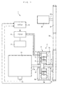
- FIG. 1 schematically shows an accessory drive system 1 according to the present embodiment together with an internal combustion engine 21 and an accessory 22.
- the internal combustion engine (hereinafter simply referred to as “the engine") 21 is e.g. a gasoline engine installed on a vehicle (not shown), and is equipped with a crank angle sensor 15.
- the crank angle sensor 15 detects the crank angle position of a crankshaft 21a (output shaft) of the engine 21, and delivers a signal indicative of the sensed crank angle position to an ECU 13, described hereinafter.
- the accessory 22 is e.g. a compressor of an automotive air conditioner, and has an input shaft 22a thereof integrally formed with an input pulley 8.
- the accessory drive system 1 is comprised of a power transmission drive system 2 connected to the engine 21, a PDU 11 connected to the power transmission drive system 2, a battery 12, and the ECU 13.
- the power transmission drive system 2 has the function of converting electric power supplied from the battery 12 into a driving force to output the same from an output shaft 4, referred to hereinafter, and the function of outputting part of a driving force input from the engine 21 from the output shaft 4, and converting the rest of the input driving force into electric power for power generation. Detailed description thereof will be given hereinafter.
- the output shaft 4 is integrally formed with an output pulley 9, and a belt 10 extends around the output pulley 9 and the above-mentioned input pulley 8. With this arrangement, the driving force from the output shaft 4 is input to the accessory 22 via the input and output pulleys 8 and 9 and the belt 10 to thereby drive the accessory 22.
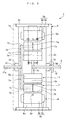
- the power transmission drive system 2 is comprised of a casing 3, the output shaft 4, a first rotor 5 disposed in the casing 3, a stator 6 disposed within the casing 3 in a manner opposed to the first rotor 5, and a second rotor 7 disposed between the two 5 and 6 at predetermined spaced intervals.
- the first rotor 5, the second rotor 7, and the stator 6 are radially arranged from the inner side in the mentioned order.
- the casing 3 includes a hollow cylindrical peripheral wall 3a, and side walls 3b and 3c arranged on opposite side ends of the peripheral wall 3a in a manner opposed to each other, which are integrally formed with each other.
- the side walls 3b and 3c have annular plate-shapes having holes 3d and 3e formed in the respective centers thereof, and the outer diameters thereof are equal to that of the peripheral wall 3a.
- the peripheral wall 3a and the side walls 3b and 3c are arranged concentrically with each other.
- bearings 3f and 3g are fitted in the above holes 3d and 3e, respectively.
- the crankshaft 21a of the engine 21 is rotatably fitted in the former 3f, and the output shaft 4 is rotatably supported by the latter 3g.
- the output shaft 4 is disposed concentrically with the crankshaft 21a. It should be noted that the output shaft 4 is made substantially axially immovable by a thrust bearing (not shown).
- a thrust bearing not shown.
- the left side and the right side as viewed in FIG. 2 will be referred to as “left” and “right” as deemed appropriate.
- the first rotor 5 has 2n permanent magnets 5a (first magnetic poles and second magnetic poles).
- the permanent magnets 5a are mounted on the outer peripheral surface of an annular fixing portion 5b in a state arranged at equal intervals in the circumferential direction of the output shaft 4 (hereinafter simply referred to as "in the circumferential direction” or “circumferentially”).
- Each permanent magnet 5a has a generally sector-shaped cross-section orthogonal to a direction in the axial direction of the output shaft 4 (hereinafter simply referred to as “in the axial direction” or “axially”), and slightly extends in the axial direction.
- the above-mentioned fixing portion 5b is formed of a soft magnetic material element, e.g. iron, and has an inner peripheral surface thereof attached to the outer peripheral surface of a disk-shaped flange 5c integrally concentrically formed with the output shaft 4. With the above arrangement, the permanent magnets 5a are rotatable in unison with the output shaft 4.
- a central angle formed by each two permanent magnets 5a circumferentially adjacent to each other about the output shaft 4 is a predetermined angle ⁇ .
- the two permanent magnets 5a circumferentially adjacent to each other have polarities different from each other.
- respective magnetic poles on the left side and the right side of each permanent magnet 5a are referred to as "the first magnetic pole” and "the second magnetic pole", respectively.
- the stator 6 generates rotating magnetic fields, and has 3n armatures 6a (first armatures and second armatures) arranged at equal intervals in the circumferential direction.
- Each armature 6a is comprised of an iron core 6b and a coil 6c wound around the iron core 6b.
- the iron core 6b has a generally sector-shaped cross-section orthogonal to the axial direction, and has approximately the same axial length as that of the permanent magnet 5a.
- An axially central portion of the inner peripheral surface of the iron core 6b is formed with a circumferentially extending groove 6d.
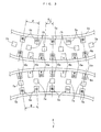
- the 3n coils 6c form n sets of three-phase coils of U-phase coils, V-phase coils, and W-phase coils (see FIG. 3 ).
- the armatures 6a are mounted on the inner peripheral surface of the peripheral wall 3a via an annular fixing portion 6e such that the armatures 6a are immovable.
- the numbers and the arrangements of the armatures 6a and the permanent magnets 5a mentioned above, causes, when the center of a certain armature 6a circumferentially coincides with the center of a certain permanent magnet 5a, the center of every three armatures 6a from the armature 6a, and the center of every two permanent magnets 5a from the permanent magnet 5a circumferentially coincides with each other.
- each armature 6a is connected to the battery 12 and the ECU 13 via the PDU 11, and configured such that when electric power is supplied or generated, magnetic poles having different polarities from each other are generated on the left and right ends of the iron core 6b, respectively. Further, in accordance with generation of these magnetic poles, first and second rotating magnetic fields are generated between the left portion of the first rotor 5 (on the first magnetic pole side) and the left end of the iron core 6b, and between the right portion of the first rotor 5 (on the second magnetic pole side) and the right end of the iron core 6b in a circumferentially rotating manner, respectively.
- the magnetic poles generated on the left and right ends of the iron core 6b are referred to as “the first armature magnetic pole” and “the second armature magnetic pole”. Further, the number of the first armature magnetic poles and that of the second armature magnetic poles are the same as the number of the magnetic poles of the permanent magnets 5a, that is, 2n, respectively.
- the second rotor 7 has a plurality of first cores 7a (first soft magnetic material elements) and a plurality of second cores 7b (second soft magnetic material elements).
- the first and second cores 7a and 7b are arranged at equal intervals in the circumferential direction, respectively, and the numbers of 7a and 7b are both set to the same number as that of the permanent magnets 5a, that is, 2n.
- Each first core 7a is formed by laminating soft magnetic material elements, such as a plurality of steel plates, such that it has a generally sector-shaped cross-section orthogonal to the axial direction, and extends by a length approximately equal to half of the length of the permanent magnet 5a in the axial direction.
- each second core 7b is formed by laminating a plurality of steel plates, such that it has a generally sector-shaped cross-section orthogonal to the axial direction, and extends by a length approximately equal to half of the length of the permanent magnet 5a in the axial direction.
- the first and second cores 7a and 7b are mounted on an outer end of a disk-shaped flange 7e by bar-shaped connecting portions 7c and 7d slightly extending in the axial direction, respectively.
- the flange 7e is integrally concentrically fitted on the crankshaft 21a. With this arrangement, the first and second cores 7a and 7b are rotatable in unison with the crankshaft 21a.
- first cores 7a are each axially arranged between the left portion of the first rotor 5 (on the first magnetic pole side) and the left portion of the stator 6 (on the first armature magnetic pole side), and the second cores 7b are each axially arranged between the right portion of the first rotor 5 (on the second magnetic pole side) and the right portion of the stator 6 (on the second armature magnetic pole side).
- the second cores 7b are circumferentially alternately arranged with respect to the first cores 7a, and the center of the second core 7b is displaced by half of the aforementioned predetermined angle ⁇ from the center of the first core 7a.
- the power transmission drive system 2 is provided with a rotational angle sensor 16.
- the rotational angle sensor 16 delivers a signal indicative of a rotational angle position to the ECU 13.
- the PDU 11 and the ECU 13 are for controlling the power transmission drive system 2.
- the former 11 is implemented by an electric circuit comprised of an inverter
- the latter 13 is implemented by a microcomputer including an I/O interface, a CPU, a RAM, and a ROM.
- the ECU 13 determines the relative positional relationship between the permanent magnets 5a, the armatures 6a, and the first and second cores 7a and 7b, based on the detected rotational angle position of the first rotor 5 and the detected crank angle position, and controls energization of the three-phase coils 6c of the armatures 6a based on the positional relationship to thereby control the first and second rotating magnetic fields.
- each first core 7a is in a position between each first magnetic pole and each first armature magnetic pole
- each second core 7b is in a position between each two pairs of second magnetic poles and second armature magnetic poles circumferentially adjacent to each other.
- each first core 7a is in a position between each two pairs of first armature magnetic poles and first magnetic poles circumferentially adjacent to each other.
- the friction of the engine 21 acts on the second rotor 7, that is, the first and second cores 7a and 7b. Since the friction is by far larger than torque required for driving the accessory 22, the first and second cores 7a and 7b are in an almost unrotatable state. In such a state, the ECU 13 controls the PDU 11 to thereby supply the stator 6 with electric power to generate the first and second rotating magnetic fields, whereby the output shaft 4 integrally formed with the first rotor 5 is rotated for driving the accessory 22.
- FIG. 3 the armatures 6a and the fixing portion 6e are shown as if they were divided into two other parts since FIG. 3 is shown as a development view, actually, they are integrally formed with each other, so that the arrangement in FIG. 3 can be shown as in FIG. 4 as equivalent thereto. Therefore, hereinafter, the operation of the power transmission drive system 2 is described assuming that the permanent magnets 5a, the armatures 6a, and the first and second cores 7a and 7b are arranged as shown in FIG. 4 .
- the operation of the power transmission drive system 2 is described by replacing the motions of the first and second rotating magnetic fields by equivalent physical motions of 2n imaginary permanent magnets (hereinafter referred to as the "imaginary magnets") VM, equal in number to the permanent magnets 5a.
- imaging magnets 2n imaginary permanent magnets
- a magnetic pole at a left-side portion of each imaginary magnet VM (on the first magnetic pole side), and a magnetic pole at a right-side portion of the imaginary magnet VM (on the second magnetic pole side) are regarded as first and second armature magnetic poles, respectively, and that a rotating magnetic field generated between the left-side portion of the imaginary magnet VM and the left portion of the first rotor 5 (on the first magnetic pole side) and a rotating magnetic field generated between the right-side portion of the imaginary magnet VM and the right portion of the first rotor 5 (on the second magnetic pole side) are regarded as first and second rotating magnetic fields, respectively.
- the left-side portion and the right-side portion of the permanent magnet 5a are referred to as "the first magnet portion” and "the second magnet portion”.
- the first and second rotating magnetic fields are generated in a manner rotated downward, as viewed in the figure, from a state in which each first core 7a is opposed to each first magnet portion, and each second core 7b is in a position between each adjacent two of the second magnet portions.
- the polarity of each first armature magnetic pole is made different from the polarity of each opposed one of the first magnetic poles, and the polarity of each second armature magnetic pole is made the same as the polarity of each opposed one of the second magnetic poles.
- first magnetic force lines G1 magnetic lines G1 of force
- second magnetic force lines G2 magnetic lines G2 of force
- the first magnetic force lines G1 are generated such that they each connect a first magnetic pole, a first core 7a, and a first armature magnetic pole
- the second magnetic force lines G2 are generated such that they each connect each circumferentially adjacent two second armature magnetic poles and a second core 7b located therebetween, and connect each circumferentially adjacent two second magnetic poles and the second core 7b located therebetween.
- the first magnetic force lines G1 are linear, no magnetic forces for circumferentially rotating the first magnet portion act on the first magnet portions.
- the two second magnetic force lines G2 between the circumferentially adjacent two second armature magnetic poles and the second core 7b are equal to each other in the degree of bend thereof and in the total magnetic flux amount.
- the two second magnetic force lines G2 between the circumferentially adjacent two second magnetic poles and the second core 7b are equal to each other in the degree of bend thereof and in the total magnetic flux amount.
- the second magnetic force lines G2 are balanced. Therefore, no magnetic forces for circumferentially rotating the second magnet portions act on the second magnet portions. From the above, the permanent magnets 5a are held at rest.
- the first magnetic force lines G1 between the first magnetic poles and the first cores 7a are large, the first magnetic force lines G1 are straight, and hence no magnetic forces are generated which cause the first magnet portions to rotate with respect to the first cores 7a.
- the distance between second magnetic poles and second armature magnetic poles having a polarity different from that of the second magnetic poles is relatively large, so that although the total magnetic flux amounts of the second magnetic force lines G2 between the second cores 7b and the second magnetic poles are relatively small, the degree of bend of the second magnetic force lines G2 is large, which causes such magnetic forces to act on the second magnet portions as make the second magnet portions closer to the second cores 7b.
- the permanent magnets 5a to be driven in the direction of rotation of the imaginary magnets VM, that is, in a direction (upward, as viewed in FIG. 5 ) opposite to the direction of rotations of the first and second rotating magnetic fields (hereinafter referred to as the "magnetic field rotation direction"), and be rotated toward respective positions shown in FIG. 5(c) .
- the first rotors 5 rotate in unison with the output shaft 4 in a direction opposite to the magnetic field rotation direction.
- the imaginary magnets VM rotate toward respective positions shown in FIG. 5(d) .
- the second magnet portions become closer to the second cores 7b to make the degree of bend of the second magnetic force lines G2 between the second cores 7b and the second magnetic poles smaller, the imaginary magnets VM become further closer to the second cores 7b, which increases the total magnetic flux amounts of the second magnetic force lines G2.
- such magnetic forces as make the second magnet portions closer to the second cores 7b act on the second magnet portions, whereby the permanent magnets 5a are driven in the direction opposite to the magnetic field rotation direction.
- the first magnetic force lines G1 between the first magnetic poles and the first cores 7a are bent along with the rotation of the permanent magnets 5a, whereby such magnetic forces as make the first magnet portions closer to the first cores 7a act on the first magnet portions.
- a magnetic force caused by the first magnetic force line G1 is smaller than the aforementioned magnetic force caused by the second magnetic force lines G1, since the degree of bend of the first magnetic force line G1 is smaller than that of the second magnetic force lines G1.
- a magnetic force corresponding to the difference between the two magnetic forces drives the permanent magnet 5a in the direction opposite to the magnetic field rotation direction.
- the total magnetic flux amount and the degree of bend of the first magnetic force line G1 between the first magnetic pole and the first core 7a become approximately equal to the total magnetic flux amount and the degree of bend of the second magnetic force lines G1 between the second core 7b and the second magnetic pole, respectively.
- the magnetic forces caused by the first and second magnetic force lines G1 and G2 are approximately balanced, whereby the permanent magnet 5a is temporarily placed in an undriven state.
- the permanent magnets 5a are driven in the direction opposite to the magnetic field rotation direction, by respective magnetic forces corresponding to the differences between the magnetic forces caused by the first magnetic force lines G1 between the first magnetic poles and the first cores 7a and the magnetic forces caused by the second magnetic force lines G2 between the second cores 7b and the second magnetic poles.
- the permanent magnets 5a are driven by the magnetic forces caused by the first magnetic force lines G1.
- the magnetic forces, that is, the driving forces thus act on the output shaft 4 alternately, whereby the torque of the output shaft 4 is made approximately constant.
- the driving force of the output shaft 4 is input to the accessory 22 via the input and output pulleys 8 and 9, and the belt 10, whereby the accessory 22 is driven.
- first and second magnetic force lines G1 and G2 act to rotate the permanent magnets 5a, i.e. the first rotor 5, with the first and second cores 7a and 7b being held at respective intermediate locations each between a first magnetic pole and a first armature magnetic pole and between a second magnetic pole and a second armature magnetic pole.
- the ECU 13 calculates the rotor rotational speed VR based on the crank angle position of the first rotor 5 detected by the above-mentioned rotational angle sensor 16, and controls the magnetic field rotational speed VF such that the calculated rotor rotational speed VR becomes equal to a predetermined value VREF (see FIG. 8(a) ). This holds the rotational speed of the input shaft 22a of the accessory 22 at a predetermined value suitable for the operation of the accessory 22.
- the crankshaft 21a since the crankshaft 21a is rotating, the second rotor 7 connected thereto, that is, the first and second cores 7a and 7b as well rotate. Further, as described hereinabove, the first and second cores 7a and 7b are magnetized by the first and second magnetic poles of the permanent magnets 5a opposed thereto. Thus, the magnetized first and second cores 7a and 7b rotate relative to the stator 6, and the ECU 13 controls the PDU 11, whereby an induced electromotive force is generated in the armatures 6a to generate electric power.
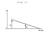
- the magnetic field rotational speed VF, the rotor rotational speed VR, and the crankshaft rotational speed VC satisfy the following relationship:
- the magnetic forces caused by the first and second magnetic force lines G1 and G2 act to rotate the permanent magnets 5a, with the first and second cores 7a and 7b being held at respective intermediate locations each between a first magnetic pole and a first armature magnetic pole and between a second magnetic pole and a second armature magnetic poles. Therefore, the crankshaft rotational speed VC of the crankshaft 21 integrally formed with the first and second cores 7a and 7b becomes equal to an average value of the sum of the magnetic field rotational speed VF and the rotor rotational speed VR.
- the ECU 13 controls the magnetic field rotational speed VF by controlling the frequency of electric current flowing through the armatures 6a such that the rotor rotational speed VR becomes equal to the predetermined value VREF.
- the magnetic field rotational speed VF is controlled to become twice as high as the crankshaft rotational speed VC. This controls the rotor rotational speed VR to 0, whereby the accessory 22 is stopped, and approximately 100 % of the driving force of the engine 21 input to the power transmission drive system 2 is converted to electric power.
- the present embodiment differently from the above-described conventional accessory drive system, it is possible to drive the accessory 22 when the engine 21 is in stoppage and in operation without using the clutch. Therefore, the omission of the clutch makes it possible to achieve downsizing and reduction of manufacturing costs of the accessory drive system 1. Further, since no clutch noises are generated, it is possible to enhance marketability. Furthermore, since the stator generating the first and second rotating magnetic fields is formed by a single stator 6, it is possible to achieve further downsizing of the accessory drive system 1 and further reduction of manufacturing costs thereof.
- a power transmission drive system 2A is mainly distinguished from the above-described power transmission drive system 2 in that the stator 6, the second rotor 7, and the first rotor 5 are arranged from a radially inner side in the mentioned order.
- component elements of the power transmission drive system 2A identical to those of the power transmission drive system 2 are designated by identical reference numerals.
- a description will be mainly given of points different from the above-described embodiment.
- the armatures 6a are mounted on a disk-shaped fixing portion 6f.
- the fixing portion 6f is fixed to the engine 21 by a connecting portion 6g.
- the armatures 6a i.e. the stator 6 is configured to be immovable.
- the permanent magnets 5a are mounted on the inner peripheral surface of an annular fixing portion 5d.
- the outer peripheral surface of the annular fixing portion 5d is integrally attached to the inner peripheral surface of an annular pulley 9A.
- the aforementioned belt 10 extends around the pulley 9A.
- the above fixing portion 5d is connected to one end of a hollow cylindrical first connecting portion 5e.
- the other end of the first connecting portion 5e is connected to a hollow shaft 5g by a second connecting portion 5f in the form of an annular plate.
- the shaft 5g is rotatably supported by a bearing 5h, and has the crankshaft 21a concentrically rotatably fitted therein.
- the pulley 9A is configured to be rotatable in unison with the permanent magnets 5a.
- the armatures 6a and the permanent magnets 5a are arranged at equal intervals in the circumferential direction, respectively, and the numbers thereof are the same as those of the above-described embodiment.
- the output pulley 9 is provided separately from the stator 6 and so forth, in the power transmission drive system 2A, the first rotor 5, the stator 6, and the second rotor 7 are arranged within the pulley 9A, which makes it possible to further downsize the accessory drive system 1.
- a power transmission drive system 2B is mainly distinguished from the power transmission drive system 2 in that it is directly connected to an accessory 23 without using a pulley or a belt.
- the accessory 23 is an oil pump, for example.
- the fixing portion 5b of the first rotor 5 is directly connected to an input shaft 23a of the accessory 23 by a hollow cylindrical connecting portion 5i.
- the input shaft 23a is formed to be hollow, and is rotatably supported by a bearing 3f.
- the crankshaft 21a is concentrically rotatably fitted through the input shaft 23a.
- a power transmission drive system 2C is distinguished from the power transmission drive system 2 only in that the first rotor 5 and the second rotor 7 are connected to the crankshaft 21a and the accessory 22, respectively.
- a description will be given of the operation of the power transmission drive system 2C.
- the friction of the engine 21 acts on the first rotor 5, that is, the permanent magnets 5a. Since the friction is by far larger than torque required for driving the accessory 22, the permanent magnets 5a are in a substantially unrotatable state. In such a state, the ECU 13 controls the PDU 11 to thereby supply the stator 6 with electric power to generate the first and second rotating magnetic fields, whereby the output shaft 4 integrally formed with the second rotor 7 is rotated to drive the accessory 22.
- the operation of the power transmission drive system 2C is described by assuming that similarly to the above-described embodiment, the permanent magnets 5a, the armatures 6a, and the first and second cores 7a and 7b are arranged as shown in FIG. 4 , and by replacing the motion of the first and second rotating magnetic fields by physical motions of imaginary permanent magnets VM equivalent thereto.
- the description will be given assuming that the magnetic pole on the left-side portion of the imaginary magnet VM (on the first magnetic pole side) and the magnetic pole on the right-side portion of the imaginary magnet VM (on the second magnetic pole side) are regarded as the first and second armature magnetic poles, respectively, and that the rotating magnetic fields generated between the left-side portions of the imaginary magnets VM and the left portions of the first rotor 5 (on the first magnetic pole side), and between the right-side portions of the imaginary magnets VM and the right portions of the first rotor 5 (on the second magnetic pole side) are regarded as the first and second rotating magnetic fields. Furthermore, hereinafter, the left portion and the right portion of each permanent magnet 5a are referred to as "the first magnet portion” and "the second magnet portion".
- the first and second rotating magnetic fields are generated in a manner rotated downward, as viewed in the figure, from a state in which each first core 7a is opposed to each first magnet portion, and each second core 7b is in a position between each adjacent two of the second magnet portions.
- the polarity of each first armature magnetic pole is made different from the polarity of an opposed one of the first magnetic poles, and the polarity of each second armature magnetic pole is made the same as the polarity of an opposed one of the second magnetic poles.
- magnetic circuits as shown in FIG. 7(a) are formed.
- the second magnetic force lines G2 are generated such that they connect between the second armature magnetic poles, the second cores 7b, and the second magnetic poles, and the first magnetic force lines G1 between the first cores 7a and the first armature magnetic poles are bent.
- magnetic circuits are formed by the first magnetic force lines and the second magnetic force lines, as shown in FIG. 7(b) .
- each first magnetic force line G1 since the degree of bend of each first magnetic force line G1 is small but the total magnetic flux amount thereof is large, a relatively large magnetic force acts on the first core 7a. This causes the first cores 7a to be driven by relatively large driving forces in the direction of rotation of the imaginary magnets VM, that is, the magnetic field rotation direction, whereby the output shaft 4 connected to the first cores 7a rotates in the magnetic field rotation direction. Further, since the degree of bend of the second magnetic force lines G1 is large but the total magnetic flux amount thereof is small, a relatively small magnetic force acts on the second core 7b. This causes the second cores 7b to be driven by relatively small driving forces in the magnetic field rotation direction, whereby the output shaft 4 connected to the second cores 7b rotates in the magnetic field rotation direction.
- the first and second cores 7a and 7b are driven in the magnetic field rotation direction by magnetic forces caused by the first and second magnetic force lines G1 and G2, so that the output shaft 4 rotates in the magnetic field rotation direction.
- the first magnetic force lines G1 increase in the degree of bend thereof but decrease in the total magnetic flux amount thereof, whereby the magnetic forces acting on the first cores 7a progressively decrease to progressively decrease the driving forces for driving the first cores 7a in the magnetic field rotation direction.
- the second magnetic force lines G2 decrease in the degree of bend thereof but increase in the total magnetic flux amount thereof, whereby the magnetic forces acting on the second cores 7b progressively increase to progressively increase the driving forces for driving the second cores 7b in the magnetic field rotation direction.
- the output shaft 4 rotates in the magnetic field rotation direction, while alternately repeating respective states in which the driving forces acting on the respective first and second core 7a and 7b increase and decrease by turns in accordance with the rotation of the imaginary magnets VM, that is, the rotations of the first and second rotating magnetic fields.
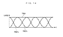
- the relationship between the driving forces TRQ7a and TRQ7b acting on the respective first and second cores 7a and 7b (hereinafter referred to as the "first driving force” and “the second driving force”, respectively), and the torque TRQ4 of the output shaft 4 (hereinafter referred to as the "shaft torque”) is as shown in FIG. 14 .
- the first and second driving forces TRQ7a and TRQ7b change approximately sinusoidally at the same repetition period, and phases thereof are displaced from each other by a half period.
- the shaft torque TRQ4 is equal to the sum of the first and second driving forces TRQ7a and TRQ7b that change as described above, and becomes approximately constant.
- the driving force of the output shaft 4 is input to the accessory 22 via the input and output pulleys 8 and 9, and the belt 10, whereby the accessory 22 is driven.
- the first and second cores 7a and 7b are rotated by the magnetic forces caused by the first and second magnetic force lines G1 and G2, and therefore the first and second cores 7a and 7b are rotated in a state slightly delayed relative to the first and second rotating magnetic fields.
- the first and second cores 7a and 7b are actually in respective positions slightly shifted in a direction (upward, as viewed in the figure) opposite to the magnetic field rotation direction with respect to the positions shown in FIG. 13(c) .
- the first and second cores 7a and 7b are presented in the positions shown in the figure.
- the rotational angle sensor 16 detects a rotational angle position of the second rotor 7, and delivers a signal indicative of the sensed rotational angle position to the ECU 13.
- the ECU 13 calculates the second rotor rotational speed VR2 based on the rotational angle position of the second rotor 7, and controls the magnetic field rotational speed VF such that the calculated second rotor rotational speed VR2 becomes equal to the predetermined value VREF (see FIG. 15(a) ). This holds the rotational speed of the input shaft 22a of the accessory 22 at a predetermined value suitable for the operation of the accessory 22.
- the ECU 13 causes electric power to be supplied to the stator 6 to generate the first and second rotating magnetic fields, whereby the magnetic forces caused by the first and second magnetic force lines G1 and G2 act on the first and second cores 7a and 7b to thereby rotate the output shaft 4, which, as a result, drives the accessory 22.
- the magnetic forces caused by the first and second magnetic force lines G1 and G2 act to rotate the output shaft 4, with the first and second cores 7a and 7b being held at respective intermediate locations each between a first magnetic pole and a first armature magnetic pole and between a second magnetic pole and a second armature magnetic pole. Therefore, the second rotor rotational speed VR2 becomes equal to an average value of the sum of the magnetic field rotational speed VF and the crankshaft rotational speed VC.
- the ECU 13 controls the magnetic field rotational speed VF such that the second rotor rotational speed VR2 becomes equal to the predetermined value VREF. As shown in FIGS. 15(b) and 15(c) , this causes the rotor rotational speed VR to be controlled to the predetermined value VREF, and the rotational speed of the input shaft 22a of the accessory 22 to be held at the predetermined value suitable for the operation of the accessory 22, irrespective of whether the crankshaft rotational speed VC is high or low.
- the first and second rotating magnetic fields are generated in a manner such that they are rotated opposite to the direction of rotation of the crankshaft 21a, to control the magnetic field rotational speed VF thereof, whereby it is possible to control the rotor rotational speed VR to the predetermined value VREF, as indicated by a solid line in FIG. 15(d) .
- the accessory 22 As described above, during very high rotation of the engine 21, it is possible to drive the accessory 22 while generating electric power.
- the accessory 22 during operation of the engine 21, it is only required to reduce the second rotor rotational speed VR2 to a value of 0, and hence as is apparent from the above equation (2), the first and second rotating magnetic fields are controlled such that they are rotated in the opposite direction to and at the same speed as the rotation of the crankshaft 21a. More specifically, the armatures 6a are caused to generate electric power, and at the same time, the absolute value of the magnetic field rotational speed VF is controlled such that it becomes equal to the crankshaft rotational speed VC. This controls the second rotor rotational speed VR2 to 0, whereby the accessory 22 is stopped and approximately 100 % of the driving force of the engine 21 input to the power transmission drive system 2C is converted to electric power.
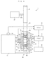
- FIG. 16 shows an accessory drive system 30 configured as such.
- the accessory drive system 30 includes the power transmission drive system 2A of the aforementioned first variation.
- the first rotor 5 is connected to the engine 21 via the first and second connecting portions 5e and 5f, a one-way clutch 24, and the connecting portion 6g.
- the one-way clutch 24 is configured such that it permits the rotation of the first rotor 5 only when the first rotor 5 rotates in the same direction as the direction of rotation of the crankshaft 21a.
- the power transmission drive system 2C of the third variation it is possible to start the engine 21.
- the first and second rotating magnetic fields are generated such that they rotate in the direction opposite to the direction of the rotation of the crankshaft 21a. This makes it possible to cause the crankshaft 21a to rotate together with the first rotor 5 by the magnetic forces caused by the first and second magnetic force lines G1 and G2, thereby making it possible to start the engine 21.
- the present invention is by no means limited to the embodiment described above, but can be practiced in various forms.
- the present invention is applied to the accessories 22 and 23, that is, a compressor and an oil pump of an automotive air conditioner, by way of example, this is not limitative, but of course the present invention can be applied to other various accessories.
- the present invention can be applied to a fuel pump and a supercharger compressor for an automotive vehicle, or accessories, such as those installed on boats, aircrafts, and the like.
- the first and second armature rows are formed by a single stator, they may be formed by two separate stators.
- the first and second magnetic poles are formed by the magnetic poles of a single permanent magnet 5a, they may be formed separately by the magnetic poles of two permanent magnets, or formed by the magnetic poles of an electromagnet.
- the permanent magnets 5a, the armatures 6a, the first and second cores 7a and 7b are arranged at equal intervals, they may be arranged at unequal intervals.
- the number of the first cores 7a is set to the same number as that of the first armature magnetic poles and that of the first magnetic poles, and the number of the second cores 7b to the same number as that of the second armature magnetic poles and that of the second magnetic poles, the numbers of the first and second cores 7a and 7b may be set to smaller numbers.
- the PDU 11 and the ECU 13 are employed as the control devices for controlling the power transmission drive systems 2 and 2A to 2C, this is not limitative, but an electric circuit or the like having a microcomputer installed thereon may be employed.
- the crankshaft rotational speed VC, the rotor rotational speed VR, and the second rotor rotational speed VR2 are calculated based on the results of detections by the crank angle sensor 15 and the rotational angle sensor 16, the detections (calculations) may be performed by other suitable arbitrary detecting means.
- crank angle position is used as a parameter indicative of the rotational angle position of the second rotor 7 and in the third variation, the same is used as a parameter indicative of the rotational angle position of the first rotor 5, this is not limitative, but it is to be understood that any other arbitrary parameters may be employed insofar as they are indicative of the rotational angle positions of the first and second rotor 5 and 7.
- the rotational angle positions of the first and second rotor 5 and 7 may be directly detected e.g. by sensors, and the results of the detections may be used.
- the rotor rotational speed VR or the second rotor rotational speed VR2 is used as a parameter indicative of the rotational speeds of the input shafts 22a and 23a of the accessories 22 and 23, this is not limitative, but it is to be understood that any other desired parameters may be employed insofar as they are indicative of the rotational speeds of the input shafts 22a and 23a of the accessories 22 and 23.
- the rotational speeds of the input shafts 22a and 23a of the accessories 22 and 23 may be directly detected e.g. by sensors, and the results of the detections may be used. It is to be further understood that various changes and modifications may be made without departing from the spirit and scope thereof.
- the accessory drive system according to the present invention is very useful in achieving downsizing of the system, reduction of manufacturing costs thereof, and enhancement of its marketability.
Landscapes
- Engineering & Computer Science (AREA)
- Power Engineering (AREA)
- Transportation (AREA)
- Mechanical Engineering (AREA)
- Hybrid Electric Vehicles (AREA)
- Permanent Magnet Type Synchronous Machine (AREA)
- Connection Of Motors, Electrical Generators, Mechanical Devices, And The Like (AREA)
Abstract
Description
- The present invention relates to an accessory drive system connected to an internal combustion engine, for driving an accessory.
- Conventionally, as an accessory drive system of this kind, one disclosed in
Patent Literature 1 is known. This accessory drive system drives an accessory, such as a compressor for an air conditioner installed on a vehicle, using an internal combustion engine (hereinafter simply referred to as "the engine") and an electric motor as drive sources, and is provided with the electric motor, first to third pulleys, and a clutch. The first pulley is provided on an output shaft of the above electric motor, the second pulley on a crankshaft of the engine, the third pulley on an input shaft of the accessory. Further, belts extend around the first to third pulleys, whereby the electric motor, the engine, and the accessory are connected to each other. A clutch is provided between the crankshaft and the second pulley, for connecting and disconnecting between the engine, the electric motor, and the accessory. - In the accessory drive system configured as above, during operation of the engine, the clutch connects the crankshaft and the accessory, whereby the accessory is driven by the engine. On the other hand, during stoppage of the engine, the clutch holds the crankshaft and the accessory in a disconnected state, and the accessory is driven by rotating the electric motor.
- As described above, in the conventional accessory drive system, since the engine and the electric motor are used as drive sources of the accessory during operation and stoppage of the engine, the engine, the electric motor, and the accessory are connected to each other. Further, to prevent the friction of the engine from acting as load on the electric motor during stoppage of the engine, the clutch is provided for disconnecting between the engine, the electric motor, and the accessory only during stoppage of the engine, and is indispensable in the conventional accessory drive system. This brings about an increase in the size of the system, and an increase in the manufacturing costs. Further, when the engine is stopped or started during driving of the accessory, it is impossible to avoid generation of clutch noises, which results in degraded marketability thereof. Furthermore, since there is a limit to speed reduction by the pulley connecting between the engine and the accessory, the rotational speed of the input shaft of the accessory becomes high during high-speed operation of the engine, and to withstand the increased rotational speed of the input shaft, it is inevitable to increase the size of the accessory.
- The present invention has been made to provide a solution to the above-described problems, and an object thereof is to provide an accessory drive system which is capable of achieving downsizing of the system, reduction of manufacturing costs thereof, and enhancement of marketability thereof.
- [Patent Literature 1] Japanese Laid-Open Patent Publication (Kokai) No.
2000-179374 - To attain the object, the invention as claimed in
claim 1 provides anaccessory drive system internal combustion engine 21, for driving anaccessory stator 6 including a first armature row which is formed by a plurality of first armatures (armatures 6a in the embodiment (the same applies hereinafter in this section)) arranged in a circumferential direction, for generating first rotating magnetic fields rotating in the circumferential direction, by magnetic poles generated in the first armatures, and a second armature row which is formed by a plurality of second armatures (armatures 6a) arranged in the circumferential direction, for generating second rotating magnetic fields rotating in a same direction as a direction of rotation of the first rotating magnetic fields, by magnetic poles generated in the second armatures, the stator being configured to be immovable, afirst rotor 5 including a first magnetic pole row which is formed by a plurality of first magnetic poles (permanent magnets 5a) arranged in the circumferential direction, each two adjacent ones of the first magnetic poles having polarities different from each other, and arranged in a manner opposed to the first armature row, a second magnetic pole row which is formed by a plurality of second magnetic poles (permanent magnets 5a) arranged in the circumferential direction, each two adjacent ones of the second magnetic poles having polarities different from each other, and is arranged in a manner opposed to the second armature row, the first rotor being connected to one of theaccessory 22 23 and an output shaft (crankshaft 21a) of theengine 21, and asecond rotor 7 including a first soft magnetic material element row which is formed by a plurality of first soft magnetic material elements (first cores 7a) arranged in the circumferential direction at predetermined intervals, and is arranged between the first armature row and the first magnetic pole row, and a second soft magnetic material element row which is formed by a plurality of second soft magnetic material elements (second cores 7b) arranged in the circumferential direction at the predetermined intervals, and is arranged between the second armature row and the second magnetic pole row, the second rotor being connected to the other of the output shafts of theaccessory - According to this accessory drive system, the first soft magnetic material element row of the second rotor is disposed between the first armature row of the stator and the first magnetic pole row of the first rotor which are opposed to each other, and the first armatures, the first magnetic poles, and the first soft magnetic material elements forming the first armature row, the first magnetic pole row, and the first soft magnetic material element row, respectively, are all arranged in the circumferential direction. Further, each adjacent two of the first soft magnetic material elements are spaced by a predetermined distance. Further, the second soft magnetic material element row of the second rotor is disposed between the second armature row of the stator and the second magnetic pole row of the first rotor which are opposed to each other, and the second armatures, the second magnetic poles, and the second soft magnetic material elements forming the second armature row, the second magnetic pole row, and the second soft magnetic material element row, respectively, are all arranged in the circumferential direction. Further, each adjacent two of the second soft magnetic material elements are spaced by a predetermined distance. Further, the first and second rotating magnetic fields rotate in the same circumferential direction, and the stator is configured to be immovable, with the first rotor being connected to one of the accessory and the output shaft of the engine, and the second rotor being connected to the other of the accessory and the output shaft of the engine.
- As described above, the first soft magnetic material element row is disposed between the first armature row and the first magnetic pole row, and therefore, each first soft magnetic material element is magnetized by a magnetic pole generated on a first armature (hereinafter referred to as the "first armature magnetic pole") and a first magnetic pole. Thus, since each first soft magnetic material element is magnetized and each adjacent two of first soft magnetic material elements are spaced, a magnetic line of force (hereinafter referred to as the "first magnetic force line") is generated between the first armature magnetic pole, the first soft magnetic material element, and the first magnetic pole. Similarly, since the second soft magnetic material element row is disposed between the second armature magnetic row and the second magnetic pole row, each second soft magnetic material element is magnetized by a magnetic pole generated on a second armature (hereinafter referred to as the "second armature magnetic pole") and a second magnetic pole. Thus, since each second soft magnetic material element is magnetized and each adjacent two second soft magnetic material elements are spaced, a magnetic line of force (hereinafter referred to as the "second magnetic force line") is generated between the second armature magnetic pole, the second soft magnetic material element, and the second magnetic pole.
- In the first place, a description will be given of the operation during stoppage of an internal combustion engine (hereinafter referred to as the "engine") in the case of the first rotor being connected to an accessory and the second rotor being connected to the output shaft of the engine. In a state where each first armature magnetic pole and each first magnetic pole in the first opposed position have polarities different from each other, if each first soft magnetic material element is between the first armature magnetic pole and the first magnetic pole, each second armature magnetic pole and each second magnetic pole in the second opposed position have the same polarity, and each second soft magnetic material element is in a position between two pairs of second armature magnetic poles and second magnetic poles adjacent to each other in the second predetermined direction.
- From this state, as the second rotating magnetic fields start rotation, each second armature magnetic pole moves away from the second opposed position in which it is opposed to each second magnetic pole having the same polarity, and moves closer to the second soft magnetic material element in a position between the two adjacent pairs of second armature magnetic poles and second magnetic poles.
- In general, when the magnetic force line is bent due to presence of a soft magnetic material element between two magnetic poles different in polarity, magnetic force (attractive force) acts on the soft magnetic material element and the two magnetic poles such that the length of the magnetic force line is reduced, and the magnetic force has a characteristic that it becomes larger as the degree of bend of the magnetic force line is larger and the total amount of magnetic flux thereof is larger. Further, the friction of the engine acts on the second rotor, that is, the first and second soft magnetic material elements. Since the friction is by far larger than torque required for driving the accessory, the first and second soft magnetic material elements are in an almost unrotatable state.
- Therefore, as the second armature magnetic pole becomes closer to the second soft magnetic material element, as described above, the total magnetic flux amount of the second magnetic force line, which is large in the degree of bend, between the second soft magnetic material element and the second magnetic pole increases, so that a relatively large magnetic force acts on the second magnetic pole such that the second magnetic force line becomes shorter, in other words, the second magnetic pole is made closer toward the second soft magnetic material element. Accordingly, the second magnetic poles are driven to be closer to the second soft magnetic material elements, so that the first rotor rotates in the direction opposite to the direction of rotation of the first and second rotating magnetic fields (hereinafter referred to as the "magnetic field rotation direction").
- Then, as the second armature magnetic poles become still closer to the second soft magnetic material elements, the second magnetic poles are also driven to become further closer to the second soft magnetic material elements. As a result, the second armature magnetic poles are brought to the respective second opposed positions in which they are opposed to the second magnetic poles different in polarity with the second soft magnetic material elements positioned therebetween. In this state, as described above, the first armature magnetic poles are in the first opposed position opposed to the first magnetic poles having the same polarity, and each first soft magnetic material element is between two pairs of first armature magnetic poles and first magnetic poles which are adjacent to each other in the circumferential direction.
- From this state, as the first rotating magnetic fields start rotation, each first armature magnetic pole moves away from the first opposed position in which it is opposed to each first magnetic pole having the same polarity, and moves closer to the first soft magnetic material element in a position between the two adjacent pairs of first armature magnetic poles and first magnetic poles. The total magnetic flux amounts of the first magnetic force lines, which are large in the degree of bend, between the first soft magnetic material elements and the first magnetic poles increase, so that relatively large magnetic forces act on the first magnetic poles such that the first magnetic force lines becomes shorter, in other words, the first magnetic poles are made closer toward the first soft magnetic material elements. As a result, the first rotor rotates in the direction opposite to the magnetic field rotation direction.
- Then, as the first armature magnetic poles become still closer to the first soft magnetic material elements, the first magnetic poles are also driven to become further closer to the first soft magnetic material elements. As a result, the first armature magnetic poles are brought to the respective first opposed positions in which they are opposed to the first magnetic poles different in polarity with the first soft magnetic material elements positioned therebetween. In this state, as described above, the second armature magnetic poles are in the respective second opposed positions opposed to the second magnetic poles having the same polarity, and each second soft magnetic material element is between two pairs of second armature magnetic poles and second magnetic poles which are adjacent to each other in the circumferential direction.
- As described above, as the first and second rotating magnetic fields rotate, the magnetic forces alternately act on the first and second magnetic poles, whereby the first rotor rotates with substantially constant torque. Since the first rotor is connected to the accessory, as described above, the torque of the first rotor is transmitted to the accessory, so that the accessory is driven. As described, during stoppage of the engine, by supplying electric power to the stator to generate the first and second rotating magnetic fields, the accessory can be driven.
- Next, a description will be given of the operation during operation of the engine. As described above, the first and second soft magnetic material elements are magnetized by the opposed first and second magnetic poles. Further, the second rotor is connected to the output shaft of the engine, and hence during operation of the engine, the magnetized first and second soft magnetic material elements rotate relative to the stator, whereby an induced electromotive force is generated in the first and second armatures, for generation of electric power. As a result, even in a state where electric power is not supplied to the first and second armatures, the induced electromotive force causes the generation of the first and second rotating magnetic fields. Therefore, in this case as well, the magnetic forces caused by the first and second magnetic force lines act on the first and second magnetic poles, whereby the first rotor rotates to drive the accessory. Thus, during operation of the engine, the accessory can be driven while generating electric power.
- Next, a description will be given of the operation during stoppage of the engine in the case where the first rotor is connected to the output shaft of the engine and the second rotor is connected to the accessory. In this case, the friction of the engine acts on the first rotor, that is, the first and second magnetic poles. Since the friction is by far larger than torque required for driving the accessory, the first and second magnetic poles are in an almost unrotatable state.
- In this case as well, as described above, in a state where each first armature magnetic pole and each first magnetic pole in the first opposed position have polarities different from each other, if each first soft magnetic element is between the first armature magnetic pole and the first magnetic pole, each second armature magnetic pole and each second magnetic pole in the second opposed position have the same polarity, and each second soft magnetic material is in a position between two pairs of second armature magnetic pole and second magnetic poles adjacent to each other in the circumferential direction. In this state, the length of the first magnetic force line becomes shortest, and the total magnetic flux amount thereof becomes largest, while the second magnetic force line is large in the degree of bend thereof and largest in its length, with the smallest total magnetic flux amount.
- From this state, when the first rotating magnetic fields start to rotate, the first magnetic force lines which are large in their total magnetic flux amounts start to be bent, and hence relative large magnetic forces act on the first soft magnetic material elements such that the length of the first magnetic force lines becomes short, whereby the first soft magnetic material elements are driven in the magnetic field rotation direction to cause the rotation of the second rotor in the magnetic field rotation direction. Further, as the second rotating magnetic fields rotate simultaneously with the rotation of the first rotating magnetic fields, the second armature magnetic poles move from the respective second opposed positions in which they are opposed to second magnetic poles having the same polarity, toward ones of the second magnetic poles having a different polarity which are adjacent to those having the same polarity. In this state, although the degree of bend of the second magnetic force lines is large, the total magnetic flux amounts thereof are small, so that relative weak magnetic forces act on the second soft magnetic material elements, whereby the second soft magnetic material elements are driven in the magnetic field rotation direction by small driving forces, so that the second rotor rotates in the magnetic field rotation direction.
- Then, when the first rotating magnetic fields further rotate, although the degree of bend of the first magnetic force lines increases, the distance between the first armature magnetic poles and the first magnetic poles which having a different polarity increases to reduce the total magnetic flux amounts of the first magnetic force lines, which weakens the magnetic forces acting on the first soft magnetic material elements, to reduce the driving forces acting on the first soft magnetic material elements. Then, when each first armature magnetic pole is brought to the first opposed position in which it is opposed to the first magnetic pole having the same polarity, each first soft magnetic material element is brought to a position between two pairs of first armature magnetic poles and first magnetic pole adjacent to each other in the circumferential direction, whereby in spite of the first magnetic force line being large in the degree of bend, the total magnetic flux amount thereof becomes the minimum, so that the magnetic force acting on the first soft magnetic material element becomes weakest to reduce the driving force acting on the first soft magnetic material element to the minimum.
- Further, as the second rotating magnetic fields rotate simultaneously with the rotation of the first rotating magnetic fields, as described above, the second armature magnetic poles move from the second opposed position in which they are opposed to second magnetic poles having the same polarity, toward ones of the second magnetic poles having a different polarity which are adjacent to those having the same polarity. In this state, although the degree of bend of the second magnetic force lines becomes small, the total magnetic flux amounts increase, so that the magnetic forces acting on the second soft magnetic material elements increase to increase the driving forces acting on the second soft magnetic material elements. Then, when each second armature magnetic pole is brought to the second opposed position in which it is opposed to each second magnetic pole having a different magnetic pole therefrom, the total magnetic flux amount of the second magnetic force line becomes largest and each second soft magnetic material element rotates in a state slight delayed relative to the second armature magnetic pole, whereby the second magnetic force line is bent. Thus, the second magnetic force lines which are largest in the total magnetic flux amount are bent, whereby the magnetic forces acting on the second soft magnetic material elements become strongest, to make largest the driving force acting on the second soft magnetic material elements.
- Further, when the first rotating magnetic fields further rotate from a state in which the magnetic forces acting on the first soft magnetic material elements are substantially weakest and the magnetic forces acting on the second soft magnetic material elements are substantially strongest, although the degree of bend of the first magnetic force lines becomes small, the total magnetic flux amounts thereof increase, so that the magnetic forces acting on the first soft magnetic material elements increase to increase the driving forces acting on the first soft magnetic material elements. Then, when each first armature magnetic pole is brought to the first opposed position in which it is opposed to each first magnetic pole having a different magnetic pole therefrom, the total magnetic flux amount of the first magnetic force line becomes largest and each first soft magnetic material element rotates in a state slightly delayed relative to the first armature magnetic pole, whereby the first magnetic force line is bent. Thus, the first magnetic force lines which are largest in the total magnetic flux amount are bent, whereby the magnetic forces acting on the first soft magnetic material elements become strongest, to make largest the driving force acting on the first soft magnetic material elements.
- Further, as the second rotating magnetic fields rotate simultaneously with the rotation of the first rotating magnetic fields, as described above, the second armature magnetic poles move from the respective second opposed positions in which they are opposed to second magnetic poles having a polarity, toward ones of the second magnetic poles having the same polarity which are adjacent to those having the different polarity. In this state, although the degree of bend of the second magnetic force lines becomes large, the total magnetic flux amounts thereof decrease, so that the magnetic forces acting on the second soft magnetic material elements become weaker to reduce the driving forces acting on the second soft magnetic material elements. Then, when each second armature magnetic pole is brought to the second opposed position in which it is opposed to the second magnetic pole having the same polarity, each second soft magnetic material element is brought to a position between two pairs of second armature magnetic poles and second magnetic pole adjacent to each other in the circumferential direction, whereby in spite of the second magnetic force line being large in the degree of bend, the total magnetic flux amount thereof becomes the minimum, so that the magnetic force acting on the second soft magnetic material element becomes weakest to reduce the driving force acting on the first soft magnetic material element to the minimum.
- As described, according to the rotations of the first and second magnetic fields, the first and second soft magnetic material elements rotate together with the second rotor while alternately repeating respective states in which the driving forces acting on the first soft magnetic material elements and the driving forces acting on the second soft magnetic material elements become larger and smaller. Although such driving forces act on the first and second magnetic material elements, since the first and second soft magnetic material elements are provided on the second rotor, the actual torque of the second rotor becomes equal to the sum of the two driving forces and substantially constant. Since this second rotor is connected to the accessory, as described above, the torque of the second rotor is transmitted to the accessory, so that the accessory is driven. As described, in this case as well, during stoppage of the engine, by supplying electric power to the stator to generate the first and second rotating magnetic fields, the accessory can be driven.
- Further, as described above, even during operation of the engine, by supplying electric power to the stator to generate the first and second rotating magnetic fields, the magnetic forces caused by the first and second magnetic force lines act on the first and second soft magnetic material elements, whereby the second rotor is rotated, so that the accessory is driven.
- As described hereinbefore, in both of the cases where the first rotor is connected to the accessory, and at the same time, the second rotor is connected to the engine, and where the second rotor is connected to the accessory, and at the same time, the first rotor is connected to the engine, differently from the above-described conventional accessory drive system, it is possible to drive the accessory both during stoppage and operation of the engine without using the clutch. This makes it possible to eliminate the clutch to thereby achieve downsizing of the accessory drive system and reduction of manufacturing costs thereof. Further, since this makes it possible to prevent clutch noises from being generated when the clutch is engaged and disengaged, it is possible to enhance marketability of the accessory drive system.
- It should be noted that throughout the present specification, "when the first armature magnetic pole(s) (second armature magnetic pole(s)) and the first magnetic pole(s) (second magnetic pole(s)) are in a position opposed to each other" is not intended to limitatively mean that the two are in completely the same position in the circumferential direction, but it is intended to include that they are in respective locations slightly different from each other.
- This invention as claimed in
claim 2 is anaccessory drive system claim 1, wherein the first and second armature rows are formed by a single mutually common armature row. - With this arrangement, the first and second armature rows are formed by a single mutually common armature row, and therefore, compared with the case where the two are formed separately, the number of parts can be reduced, whereby it is possible to achieve further downsizing of the accessory drive system and further reduction of manufacturing costs thereof.
-
- [
FIG. 1 ]
A diagram schematically showing an accessory drive system according to the present embodiment together with an engine and an accessory. - [
FIG. 2 ]
An enlarged cross-sectional view of theFIG. 1 power transmission drive system. - [
FIG. 3 ]
A development view of part of a cross-section of theFIG. 1 power transmission drive system taken on line A-A ofFIG. 2 along the circumferential direction during generation of first and second rotating magnetic fields. - [
FIG. 4 ]
A diagram showing an arrangement functionally equivalent to the arrangement of theFIG. 3 development view. - [
FIG. 5 ]
A diagram which is useful in explaining operations of the power transmission drive system during stoppage of the engine. - [
FIG. 6 ]
A diagram which is useful in explaining operations continued from theFIG. 5 operation. - [
FIG. 7 ]
A diagram showing magnetic circuits formed during the operation of the power transmission drive system. - [
FIG. 8 ]
A diagram showing examples of velocity diagrams representative of the relationship between a magnetic field rotational speed VF, a crankshaft rotational speed VC, and a rotor rotational speed VR, in which: (a) shows an example during stoppage of the engine; (b) an example during low rotation of the engine; (c) an example during high rotation of the engine; and (d) an example during very low rotation of the engine. - [
FIG. 9 ]
A diagram schematically showing an accessory drive system according to a first variation together with an engine and an accessory. - [
FIG. 10 ]
A diagram schematically showing an accessory drive system according to a second variation together with an engine and an accessory. - [
FIG. 11 ]
An enlarged cross-sectional view of a power transmission drive system according to a third variation. - [
FIG. 12 ]
A diagram which is useful in explaining operations of theFIG. 11 power transmission drive system during stoppage of the engine. - [
FIG. 13 ]
A diagram which is useful in explaining operations continued from theFIG. 12 operation. - [
FIG. 14 ]
A diagram schematically showing the relationship between a first driving force, a second driving force, and a shaft torque. - [
FIG. 15 ]
A diagram showing examples of velocity diagrams representative of the relationship between the magnetic field rotational speed VF, a second rotor rotational speed VR2, and the crankshaft rotational speed VC, in which: (a) shows an example during stoppage of the engine; (b) an example during low rotation of the engine; (c) an example during high rotation of the engine; and (d) an example during very high rotation of the engine. - [
FIG. 16 ]
A diagram schematically showing an accessory drive system used as a starter for starting the engine, together with the engine and the accessory. - [
FIG. 17 ]
A diagram showing a velocity diagram representative of the relationship between the magnetic field rotational speed VF, the crankshaft rotational speed VC, and the rotor rotational speed VR of theFIG. 16 accessory drive system during the start of the engine. - The present invention will now be described in detail with reference to the drawings showing a preferred embodiment thereof. It should be noted that in the figures, hatching in portions illustrating cross-sections are omitted for convenience.
FIG. 1 schematically shows anaccessory drive system 1 according to the present embodiment together with aninternal combustion engine 21 and anaccessory 22. The internal combustion engine (hereinafter simply referred to as "the engine") 21 is e.g. a gasoline engine installed on a vehicle (not shown), and is equipped with acrank angle sensor 15. Thecrank angle sensor 15 detects the crank angle position of acrankshaft 21a (output shaft) of theengine 21, and delivers a signal indicative of the sensed crank angle position to anECU 13, described hereinafter. Theaccessory 22 is e.g. a compressor of an automotive air conditioner, and has aninput shaft 22a thereof integrally formed with aninput pulley 8. - Referring to
FIG. 1 , theaccessory drive system 1 is comprised of a powertransmission drive system 2 connected to theengine 21, aPDU 11 connected to the powertransmission drive system 2, abattery 12, and theECU 13. The powertransmission drive system 2 has the function of converting electric power supplied from thebattery 12 into a driving force to output the same from anoutput shaft 4, referred to hereinafter, and the function of outputting part of a driving force input from theengine 21 from theoutput shaft 4, and converting the rest of the input driving force into electric power for power generation. Detailed description thereof will be given hereinafter. Further, theoutput shaft 4 is integrally formed with anoutput pulley 9, and abelt 10 extends around theoutput pulley 9 and the above-mentionedinput pulley 8. With this arrangement, the driving force from theoutput shaft 4 is input to theaccessory 22 via the input andoutput pulleys belt 10 to thereby drive theaccessory 22. - As shown in
FIGS. 1 and2 , the powertransmission drive system 2 is comprised of acasing 3, theoutput shaft 4, afirst rotor 5 disposed in thecasing 3, astator 6 disposed within thecasing 3 in a manner opposed to thefirst rotor 5, and asecond rotor 7 disposed between the two 5 and 6 at predetermined spaced intervals. Thefirst rotor 5, thesecond rotor 7, and thestator 6 are radially arranged from the inner side in the mentioned order. - The
casing 3 includes a hollow cylindrical peripheral wall 3a, andside walls side walls shapes having holes side walls bearings above holes crankshaft 21a of theengine 21 is rotatably fitted in the former 3f, and theoutput shaft 4 is rotatably supported by the latter 3g. With this arrangement, theoutput shaft 4 is disposed concentrically with thecrankshaft 21a. It should be noted that theoutput shaft 4 is made substantially axially immovable by a thrust bearing (not shown). Hereinafter, the left side and the right side as viewed inFIG. 2 will be referred to as "left" and "right" as deemed appropriate. - The
first rotor 5 has 2npermanent magnets 5a (first magnetic poles and second magnetic poles). Thepermanent magnets 5a are mounted on the outer peripheral surface of anannular fixing portion 5b in a state arranged at equal intervals in the circumferential direction of the output shaft 4 (hereinafter simply referred to as "in the circumferential direction" or "circumferentially").
Eachpermanent magnet 5a has a generally sector-shaped cross-section orthogonal to a direction in the axial direction of the output shaft 4 (hereinafter simply referred to as "in the axial direction" or "axially"), and slightly extends in the axial direction. The above-mentionedfixing portion 5b is formed of a soft magnetic material element, e.g. iron, and has an inner peripheral surface thereof attached to the outer peripheral surface of a disk-shapedflange 5c integrally concentrically formed with theoutput shaft 4. With the above arrangement, thepermanent magnets 5a are rotatable in unison with theoutput shaft 4. - Further, as shown in
FIG. 3 , a central angle formed by each twopermanent magnets 5a circumferentially adjacent to each other about theoutput shaft 4 is a predetermined angle θ. Further, the twopermanent magnets 5a circumferentially adjacent to each other have polarities different from each other. Hereafter, respective magnetic poles on the left side and the right side of eachpermanent magnet 5a are referred to as "the first magnetic pole" and "the second magnetic pole", respectively. - The
stator 6 generates rotating magnetic fields, and has 3narmatures 6a (first armatures and second armatures) arranged at equal intervals in the circumferential direction. Eacharmature 6a is comprised of aniron core 6b and acoil 6c wound around theiron core 6b. Theiron core 6b has a generally sector-shaped cross-section orthogonal to the axial direction, and has approximately the same axial length as that of thepermanent magnet 5a. An axially central portion of the inner peripheral surface of theiron core 6b is formed with acircumferentially extending groove 6d. The 3n coils 6c form n sets of three-phase coils of U-phase coils, V-phase coils, and W-phase coils (seeFIG. 3 ). Further, thearmatures 6a are mounted on the inner peripheral surface of the peripheral wall 3a via anannular fixing portion 6e such that thearmatures 6a are immovable. The numbers and the arrangements of thearmatures 6a and thepermanent magnets 5a, mentioned above, causes, when the center of acertain armature 6a circumferentially coincides with the center of a certainpermanent magnet 5a, the center of every threearmatures 6a from thearmature 6a, and the center of every twopermanent magnets 5a from thepermanent magnet 5a circumferentially coincides with each other. - Furthermore, each
armature 6a is connected to thebattery 12 and theECU 13 via thePDU 11, and configured such that when electric power is supplied or generated, magnetic poles having different polarities from each other are generated on the left and right ends of theiron core 6b, respectively. Further, in accordance with generation of these magnetic poles, first and second rotating magnetic fields are generated between the left portion of the first rotor 5 (on the first magnetic pole side) and the left end of theiron core 6b, and between the right portion of the first rotor 5 (on the second magnetic pole side) and the right end of theiron core 6b in a circumferentially rotating manner, respectively. Hereinafter, the magnetic poles generated on the left and right ends of theiron core 6b are referred to as "the first armature magnetic pole" and "the second armature magnetic pole". Further, the number of the first armature magnetic poles and that of the second armature magnetic poles are the same as the number of the magnetic poles of thepermanent magnets 5a, that is, 2n, respectively. - The
second rotor 7 has a plurality offirst cores 7a (first soft magnetic material elements) and a plurality ofsecond cores 7b (second soft magnetic material elements). The first andsecond cores permanent magnets 5a, that is, 2n. Eachfirst core 7a is formed by laminating soft magnetic material elements, such as a plurality of steel plates, such that it has a generally sector-shaped cross-section orthogonal to the axial direction, and extends by a length approximately equal to half of the length of thepermanent magnet 5a in the axial direction. Similarly to thefirst core 7a, eachsecond core 7b is formed by laminating a plurality of steel plates, such that it has a generally sector-shaped cross-section orthogonal to the axial direction, and extends by a length approximately equal to half of the length of thepermanent magnet 5a in the axial direction. - The first and
second cores flange 7e by bar-shaped connectingportions flange 7e is integrally concentrically fitted on thecrankshaft 21a. With this arrangement, the first andsecond cores crankshaft 21a. - Further, the
first cores 7a are each axially arranged between the left portion of the first rotor 5 (on the first magnetic pole side) and the left portion of the stator 6 (on the first armature magnetic pole side), and thesecond cores 7b are each axially arranged between the right portion of the first rotor 5 (on the second magnetic pole side) and the right portion of the stator 6 (on the second armature magnetic pole side). Furthermore, thesecond cores 7b are circumferentially alternately arranged with respect to thefirst cores 7a, and the center of thesecond core 7b is displaced by half of the aforementioned predetermined angle θ from the center of thefirst core 7a. - Further, the power
transmission drive system 2 is provided with arotational angle sensor 16. Therotational angle sensor 16 delivers a signal indicative of a rotational angle position to theECU 13. - The
PDU 11 and theECU 13 are for controlling the powertransmission drive system 2. The former 11 is implemented by an electric circuit comprised of an inverter, and the latter 13 is implemented by a microcomputer including an I/O interface, a CPU, a RAM, and a ROM. Further, theECU 13 determines the relative positional relationship between thepermanent magnets 5a, thearmatures 6a, and the first andsecond cores first rotor 5 and the detected crank angle position, and controls energization of the three-phase coils 6c of thearmatures 6a based on the positional relationship to thereby control the first and second rotating magnetic fields. - In the power
transmission drive system 2 configured as above, as shown inFIG. 3 , during generation of the first and second rotating magnetic fields, when the polarities of first armature magnetic poles are different from the polarities of opposed (closest) ones of the first magnetic poles, the polarities of second armature magnetic poles become the same as the polarities of opposed (closest) ones of the second magnetic poles. Further, when eachfirst core 7a is in a position between each first magnetic pole and each first armature magnetic pole, eachsecond core 7b is in a position between each two pairs of second magnetic poles and second armature magnetic poles circumferentially adjacent to each other. Furthermore, although not shown, during generation of the first and second rotating magnetic fields, when the polarities of second armature magnetic poles are different from the polarities of opposed (closest) ones of the second magnetic poles, the polarities of first armature magnetic poles become the same as the polarities of opposed (closest) ones of the first magnetic poles. Further, when eachsecond core 7b is in a position between each second magnetic pole and each second armature magnetic pole, eachfirst core 7a is in a position between each two pairs of first armature magnetic poles and first magnetic poles circumferentially adjacent to each other. - Next, a description will be given of the operation of the power
transmission drive system 2 during stoppage of theengine 21. In this case, the friction of theengine 21 acts on thesecond rotor 7, that is, the first andsecond cores accessory 22, the first andsecond cores ECU 13 controls thePDU 11 to thereby supply thestator 6 with electric power to generate the first and second rotating magnetic fields, whereby theoutput shaft 4 integrally formed with thefirst rotor 5 is rotated for driving theaccessory 22. - It should be noted that although in
FIG. 3 , thearmatures 6a and the fixingportion 6e are shown as if they were divided into two other parts sinceFIG. 3 is shown as a development view, actually, they are integrally formed with each other, so that the arrangement inFIG. 3 can be shown as inFIG. 4 as equivalent thereto. Therefore, hereinafter, the operation of the powertransmission drive system 2 is described assuming that thepermanent magnets 5a, thearmatures 6a, and the first andsecond cores FIG. 4 . - Further, for convenience of description, the operation of the power
transmission drive system 2 is described by replacing the motions of the first and second rotating magnetic fields by equivalent physical motions of 2n imaginary permanent magnets (hereinafter referred to as the "imaginary magnets") VM, equal in number to thepermanent magnets 5a. Further, the description will be given assuming that a magnetic pole at a left-side portion of each imaginary magnet VM (on the first magnetic pole side), and a magnetic pole at a right-side portion of the imaginary magnet VM (on the second magnetic pole side) are regarded as first and second armature magnetic poles, respectively, and that a rotating magnetic field generated between the left-side portion of the imaginary magnet VM and the left portion of the first rotor 5 (on the first magnetic pole side) and a rotating magnetic field generated between the right-side portion of the imaginary magnet VM and the right portion of the first rotor 5 (on the second magnetic pole side) are regarded as first and second rotating magnetic fields, respectively. Furthermore, hereinafter, the left-side portion and the right-side portion of thepermanent magnet 5a are referred to as "the first magnet portion" and "the second magnet portion". - First, as shown in
FIG. 5(a) , the first and second rotating magnetic fields are generated in a manner rotated downward, as viewed in the figure, from a state in which eachfirst core 7a is opposed to each first magnet portion, and eachsecond core 7b is in a position between each adjacent two of the second magnet portions. At the start of the generation of the first and second rotating magnetic fields, the polarity of each first armature magnetic pole is made different from the polarity of each opposed one of the first magnetic poles, and the polarity of each second armature magnetic pole is made the same as the polarity of each opposed one of the second magnetic poles. - Since the
first cores 7a are arranged as described above, they are magnetized by the first magnetic poles and the first armature magnetic poles, and magnetic lines G1 of force (hereinafter referred to as the "first magnetic force lines G1") are generated between the first magnetic poles, thefirst cores 7a, and the first armature magnetic poles. Similarly, since thesecond cores 7b are arranged as described above, they are magnetized by the second armature magnetic poles and the second magnetic poles, and magnetic lines G2 of force (hereinafter referred to as the "second magnetic force lines G2") are generated between the second armature magnetic poles, thesecond cores 7b, and the second magnetic poles. - In the state shown in
FIG. 5(a) , the first magnetic force lines G1 are generated such that they each connect a first magnetic pole, afirst core 7a, and a first armature magnetic pole, and the second magnetic force lines G2 are generated such that they each connect each circumferentially adjacent two second armature magnetic poles and asecond core 7b located therebetween, and connect each circumferentially adjacent two second magnetic poles and thesecond core 7b located therebetween. As a result, in this state, magnetic circuits as shown inFIG. 7(a) are formed. - In this state, since the first magnetic force lines G1 are linear, no magnetic forces for circumferentially rotating the first magnet portion act on the first magnet portions. Further, the two second magnetic force lines G2 between the circumferentially adjacent two second armature magnetic poles and the
second core 7b are equal to each other in the degree of bend thereof and in the total magnetic flux amount. Similarly, the two second magnetic force lines G2 between the circumferentially adjacent two second magnetic poles and thesecond core 7b are equal to each other in the degree of bend thereof and in the total magnetic flux amount. As a consequence, the second magnetic force lines G2 are balanced. Therefore, no magnetic forces for circumferentially rotating the second magnet portions act on the second magnet portions. From the above, thepermanent magnets 5a are held at rest. - When the imaginary magnets VM rotate from the positions shown in
FIG. 5(a) to respective positions shown inFIG. 5(b) , the first magnetic force lines G1 between thefirst cores 7a and the first armature magnetic poles are bent, and accordingly each second armature magnetic pole becomes closer to asecond core 7b, whereby the second magnetic force lines G2 are formed such that they each connect between the second armature magnetic pole, thesecond core 7b, and a second magnetic pole. As a consequence, magnetic circuits are formed between thepermanent magnets 5a, the imaginary magnets VM, and the first andsecond cores FIG. 7(b) . - In this state, although the total magnetic flux amounts of the first magnetic force lines G1 between the first magnetic poles and the
first cores 7a are large, the first magnetic force lines G1 are straight, and hence no magnetic forces are generated which cause the first magnet portions to rotate with respect to thefirst cores 7a. Further, the distance between second magnetic poles and second armature magnetic poles having a polarity different from that of the second magnetic poles is relatively large, so that although the total magnetic flux amounts of the second magnetic force lines G2 between thesecond cores 7b and the second magnetic poles are relatively small, the degree of bend of the second magnetic force lines G2 is large, which causes such magnetic forces to act on the second magnet portions as make the second magnet portions closer to thesecond cores 7b. This causes thepermanent magnets 5a to be driven in the direction of rotation of the imaginary magnets VM, that is, in a direction (upward, as viewed inFIG. 5 ) opposite to the direction of rotations of the first and second rotating magnetic fields (hereinafter referred to as the "magnetic field rotation direction"), and be rotated toward respective positions shown inFIG. 5(c) . In accordance with this, thefirst rotors 5 rotate in unison with theoutput shaft 4 in a direction opposite to the magnetic field rotation direction. - While the
permanent magnets 5a rotate from the positions shown inFIG. 5(b) toward the respective positions shown inFIG. 5(c) , the imaginary magnets VM rotate toward respective positions shown inFIG. 5(d) . As described above, although the second magnet portions become closer to thesecond cores 7b to make the degree of bend of the second magnetic force lines G2 between thesecond cores 7b and the second magnetic poles smaller, the imaginary magnets VM become further closer to thesecond cores 7b, which increases the total magnetic flux amounts of the second magnetic force lines G2. As a result, in this case as well, such magnetic forces as make the second magnet portions closer to thesecond cores 7b act on the second magnet portions, whereby thepermanent magnets 5a are driven in the direction opposite to the magnetic field rotation direction. - Further, as the
permanent magnets 5a rotate in the direction opposite to the magnetic field rotation direction, the first magnetic force lines G1 between the first magnetic poles and thefirst cores 7a are bent along with the rotation of thepermanent magnets 5a, whereby such magnetic forces as make the first magnet portions closer to thefirst cores 7a act on the first magnet portions. In this state, however, a magnetic force caused by the first magnetic force line G1 is smaller than the aforementioned magnetic force caused by the second magnetic force lines G1, since the degree of bend of the first magnetic force line G1 is smaller than that of the second magnetic force lines G1. As a result, a magnetic force corresponding to the difference between the two magnetic forces drives thepermanent magnet 5a in the direction opposite to the magnetic field rotation direction. - Referring to
FIG. 5(d) , when the distance between the first magnetic pole and thefirst core 7a, and the distance between thesecond core 7b and the second magnetic pole have become approximately equal to each other, the total magnetic flux amount and the degree of bend of the first magnetic force line G1 between the first magnetic pole and thefirst core 7a become approximately equal to the total magnetic flux amount and the degree of bend of the second magnetic force lines G1 between thesecond core 7b and the second magnetic pole, respectively. As a result, the magnetic forces caused by the first and second magnetic force lines G1 and G2 are approximately balanced, whereby thepermanent magnet 5a is temporarily placed in an undriven state. - From this state, when the imaginary magnets VM rotate to respective positions shown in
FIG. 6(a) , the state of generation of the first magnetic force lines G1 is changed to form magnetic circuits as shown inFIG. 6(b) . Accordingly, the magnetic forces caused by the first magnetic force lines G1 almost cease to act on the first magnet portions so as to make the first magnet portions closer to thefirst cores 7a, and therefore thepermanent magnets 5a are driven by the magnetic forces caused by the second magnetic force lines G2, to respective positions shown inFIG. 6(c) , in the direction opposite to the magnetic field rotation direction. - Then, when the imaginary magnets VM slightly rotate from the respective positions shown in
FIG. 6(c) , inversely to the above, the magnetic forces caused by the first magnetic force lines G1 between the first magnetic poles and thefirst cores 7a act on the first magnet portions so as to make the first magnet portions closer to thefirst cores 7a, whereby thepermanent magnets 5a are driven in the direction opposite to the magnetic field rotation direction, to rotate theoutput shaft 4 in the direction opposite to the magnetic field rotation direction. Then, when the imaginary magnets VM further rotate, thepermanent magnets 5a are driven in the direction opposite to the magnetic field rotation direction, by respective magnetic forces corresponding to the differences between the magnetic forces caused by the first magnetic force lines G1 between the first magnetic poles and thefirst cores 7a and the magnetic forces caused by the second magnetic force lines G2 between thesecond cores 7b and the second magnetic poles. After that, when the magnetic forces caused by the second magnetic force lines G2 almost cease to act on the second magnet portions so as to make the second magnet portions closer to thesecond cores 7b, thepermanent magnets 5a are driven by the magnetic forces caused by the first magnetic force lines G1. - As described hereinabove, in accordance with the rotations of the first and second rotating magnetic fields, the magnetic forces caused by the first magnetic force lines G1 between the first magnetic poles and the
first cores 7a, the magnetic forces caused by the second magnetic force lines G2 between thesecond cores 7b and the second magnetic poles, and the magnetic forces corresponding to the differences between the above magnetic forces alternately act on thepermanent magnets 5a, i.e. on theoutput shaft 4, whereby theoutput shaft 4 is rotated in the direction opposite to the magnetic field rotation direction. Further, the magnetic forces, that is, the driving forces thus act on theoutput shaft 4 alternately, whereby the torque of theoutput shaft 4 is made approximately constant. Further, as described hereinabove, the driving force of theoutput shaft 4 is input to theaccessory 22 via the input andoutput pulleys belt 10, whereby theaccessory 22 is driven. - Also, in this case, the
first rotor 5 integrally formed with theoutput shaft 4 rotates at the same speed as that of the first and second rotating magnetic fields, in the opposite direction, and the rotational speed VR of the first rotor 5 (hereinafter referred to as the "rotor rotational speed") and the rotational speed VF of the first and second rotating magnetic fields (hereinafter referred to as the "magnetic field rotational speed") satisfy the relationship of VR = -VF. More specifically, in this case, the relationship between the magnetic field rotational speed VF, the rotor rotational speed VR, and the rotational speed VC of thecrankshaft 21a (hereinafter referred to as the "crankshaft rotational speed") is represented as shown inFIG. 8(a) . This is because the magnetic forces caused by the first and second magnetic force lines G1 and G2 act to rotate thepermanent magnets 5a, i.e. thefirst rotor 5, with the first andsecond cores - Furthermore, the
ECU 13 calculates the rotor rotational speed VR based on the crank angle position of thefirst rotor 5 detected by the above-mentionedrotational angle sensor 16, and controls the magnetic field rotational speed VF such that the calculated rotor rotational speed VR becomes equal to a predetermined value VREF (seeFIG. 8(a) ). This holds the rotational speed of theinput shaft 22a of the accessory 22 at a predetermined value suitable for the operation of theaccessory 22. - Next, a description will be given of the operation of the power
transmission drive system 2 during operation of theengine 21. In this case, since thecrankshaft 21a is rotating, thesecond rotor 7 connected thereto, that is, the first andsecond cores second cores permanent magnets 5a opposed thereto. Thus, the magnetized first andsecond cores stator 6, and theECU 13 controls thePDU 11, whereby an induced electromotive force is generated in thearmatures 6a to generate electric power. - As a result, as shown in
FIGS. 8(b) and 8(c) , even in a state where electric power is not supplied to thearmatures 6a, first and second rotating magnetic fields are generated by the induced electromotive force, and the generated first and second rotating magnetic fields rotate in a direction opposite to the direction of rotation thereof during supply of electric power to thearmatures 6a. Therefore, in this case as well, the magnetic forces caused by the first and second magnetic force lines G1 and G2 act on thepermanent magnets 5a, whereby theoutput shaft 4 rotates to drive theaccessory 22. As described above, during operation of theengine 21, it is possible to drive theaccessory 22, while generating electric power. It should be noted that electric power obtained by the generation of electric power charges thebattery 12. This makes it possible to drive theaccessory 22 using the charged electric power during the next stoppage of theengine 21. - Further, in this case, the magnetic field rotational speed VF, the rotor rotational speed VR, and the crankshaft rotational speed VC satisfy the following relationship: As described above, the magnetic forces caused by the first and second magnetic force lines G1 and G2 act to rotate the
permanent magnets 5a, with the first andsecond cores crankshaft 21 integrally formed with the first andsecond cores - Therefore, the relationship between the magnetic field rotational speed VF, the rotor rotational speed VR, and the crankshaft rotational speed VC during operation of the
engine 21 can be expressed by the following equation (1):
- Similarly to the above-described case of the operation during stoppage of the
engine 21, in this case as well, theECU 13 controls the magnetic field rotational speed VF by controlling the frequency of electric current flowing through thearmatures 6a such that the rotor rotational speed VR becomes equal to the predetermined value VREF. This causes, as shown inFIGS. 8(b) and 8(c) , the rotor rotational speed VR to be controlled to the predetermined value VREF, and the rotational speed of theinput shaft 22a of the accessory 22 to be held at the predetermined value suitable for the operation of theaccessory 22, irrespective of whether the crankshaft rotational speed VC is high or low. - Further, as shown in
FIG. 8(d) , when the crankshaft rotational speed VC is very low, it is sometimes impossible, as indicated by a broken line in the figure, to increase the rotor rotational speed VR to the predetermined value VREF, by controlling the magnetic field rotational speed VF of the first and second rotating magnetic fields generated by generation of electric power. In such a case, the first and second rotating magnetic fields are generated by supply of electric power to thearmatures 6a and the magnetic field rotational speed VF is controlled, whereby it is possible to increase the rotor rotational speed VR to the predetermined value VREF, as indicated by a solid line inFIG. 8(d) . - Further, to stop the accessory 22 during operation of the
engine 21, it is only required in this case to reduce the rotor rotational speed VR to a value of 0, and hence as is apparent from the above equation (1), the magnetic field rotational speed VF is controlled to become twice as high as the crankshaft rotational speed VC. This controls the rotor rotational speed VR to 0, whereby theaccessory 22 is stopped, and approximately 100 % of the driving force of theengine 21 input to the powertransmission drive system 2 is converted to electric power. - As described hereinbefore, according to the present embodiment, differently from the above-described conventional accessory drive system, it is possible to drive the
accessory 22 when theengine 21 is in stoppage and in operation without using the clutch. Therefore, the omission of the clutch makes it possible to achieve downsizing and reduction of manufacturing costs of theaccessory drive system 1. Further, since no clutch noises are generated, it is possible to enhance marketability. Furthermore, since the stator generating the first and second rotating magnetic fields is formed by asingle stator 6, it is possible to achieve further downsizing of theaccessory drive system 1 and further reduction of manufacturing costs thereof. - Further, during operation of the
engine 21, by controlling the magnetic field rotational speed VF, it is possible to hold the rotational speed of theinput shaft 22a of the accessory 22 at a predetermined value suitable for the operation of theaccessory 22, irrespective of whether the crankshaft rotational speed VC is high or low. Therefore, differently from the above-described conventional accessory drive system, it is possible to downsize theaccessory 22. - Next, a first variation of the embodiment described above will be described with reference to
FIG. 9 . In the first variation, a powertransmission drive system 2A is mainly distinguished from the above-described powertransmission drive system 2 in that thestator 6, thesecond rotor 7, and thefirst rotor 5 are arranged from a radially inner side in the mentioned order. In the figure, component elements of the powertransmission drive system 2A, identical to those of the powertransmission drive system 2 are designated by identical reference numerals. Hereinafter, a description will be mainly given of points different from the above-described embodiment. - The
armatures 6a are mounted on a disk-shapedfixing portion 6f. The fixingportion 6f is fixed to theengine 21 by a connectingportion 6g. With this arrangement, thearmatures 6a, i.e. thestator 6 is configured to be immovable. - Further, the
permanent magnets 5a are mounted on the inner peripheral surface of anannular fixing portion 5d. The outer peripheral surface of theannular fixing portion 5d is integrally attached to the inner peripheral surface of anannular pulley 9A. Theaforementioned belt 10 extends around thepulley 9A. Further, theabove fixing portion 5d is connected to one end of a hollow cylindrical first connectingportion 5e. The other end of the first connectingportion 5e is connected to ahollow shaft 5g by a second connectingportion 5f in the form of an annular plate. Theshaft 5g is rotatably supported by abearing 5h, and has thecrankshaft 21a concentrically rotatably fitted therein. With the above arrangement, thepulley 9A is configured to be rotatable in unison with thepermanent magnets 5a. It should be noted that similarly to the above-described embodiment, thearmatures 6a and thepermanent magnets 5a are arranged at equal intervals in the circumferential direction, respectively, and the numbers thereof are the same as those of the above-described embodiment. - With the above arrangement, it is possible to obtain the same advantageous effects as provided by the above-described embodiment. Further, although in the above-described power
transmission drive system 2, theoutput pulley 9 is provided separately from thestator 6 and so forth, in the powertransmission drive system 2A, thefirst rotor 5, thestator 6, and thesecond rotor 7 are arranged within thepulley 9A, which makes it possible to further downsize theaccessory drive system 1. - Next, a second variation of the above-described embodiment will be described with reference to
FIG. 10 . As shown in the figure, in the second variation, a powertransmission drive system 2B is mainly distinguished from the powertransmission drive system 2 in that it is directly connected to anaccessory 23 without using a pulley or a belt. Theaccessory 23 is an oil pump, for example. More specifically, the fixingportion 5b of thefirst rotor 5 is directly connected to aninput shaft 23a of the accessory 23 by a hollowcylindrical connecting portion 5i. Theinput shaft 23a is formed to be hollow, and is rotatably supported by abearing 3f. Thecrankshaft 21a is concentrically rotatably fitted through theinput shaft 23a. - With the above arrangement, it is possible to obtain the same advantageous effects as provided by the above-described embodiment. Further, compared with the above-described embodiment, since the input and
output pulleys belt 10 are omitted, it is possible to still further downsize theaccessory drive system 1 and reduce manufacturing costs thereof, accordingly. - Next, a third variation of the above-described embodiment will be described with reference to
FIG. 11 . In the third variation variation, a powertransmission drive system 2C is distinguished from the powertransmission drive system 2 only in that thefirst rotor 5 and thesecond rotor 7 are connected to thecrankshaft 21a and theaccessory 22, respectively. Hereinafter, a description will be given of the operation of the powertransmission drive system 2C. - First, a description will be given of the operation of the power
transmission drive system 2C during stoppage of theengine 21. In this case, the friction of theengine 21 acts on thefirst rotor 5, that is, thepermanent magnets 5a. Since the friction is by far larger than torque required for driving theaccessory 22, thepermanent magnets 5a are in a substantially unrotatable state. In such a state, theECU 13 controls thePDU 11 to thereby supply thestator 6 with electric power to generate the first and second rotating magnetic fields, whereby theoutput shaft 4 integrally formed with thesecond rotor 7 is rotated to drive theaccessory 22. - It should be noted that the operation of the power
transmission drive system 2C is described by assuming that similarly to the above-described embodiment, thepermanent magnets 5a, thearmatures 6a, and the first andsecond cores FIG. 4 , and by replacing the motion of the first and second rotating magnetic fields by physical motions of imaginary permanent magnets VM equivalent thereto. Further, in this case as well, the description will be given assuming that the magnetic pole on the left-side portion of the imaginary magnet VM (on the first magnetic pole side) and the magnetic pole on the right-side portion of the imaginary magnet VM (on the second magnetic pole side) are regarded as the first and second armature magnetic poles, respectively, and that the rotating magnetic fields generated between the left-side portions of the imaginary magnets VM and the left portions of the first rotor 5 (on the first magnetic pole side), and between the right-side portions of the imaginary magnets VM and the right portions of the first rotor 5 (on the second magnetic pole side) are regarded as the first and second rotating magnetic fields. Furthermore, hereinafter, the left portion and the right portion of eachpermanent magnet 5a are referred to as "the first magnet portion" and "the second magnet portion". - First, similarly to the above-described embodiment, as shown in
FIG. 12(a) , the first and second rotating magnetic fields are generated in a manner rotated downward, as viewed in the figure, from a state in which eachfirst core 7a is opposed to each first magnet portion, and eachsecond core 7b is in a position between each adjacent two of the second magnet portions. At the start of the generation of the first and second rotating magnetic fields, the polarity of each first armature magnetic pole is made different from the polarity of an opposed one of the first magnetic poles, and the polarity of each second armature magnetic pole is made the same as the polarity of an opposed one of the second magnetic poles. In this state, magnetic circuits as shown inFIG. 7(a) are formed. - When the imaginary magnets VM rotate from positions shown in
FIG. 12(a) to respective positions shown inFIG. 12(b) , the second magnetic force lines G2 are generated such that they connect between the second armature magnetic poles, thesecond cores 7b, and the second magnetic poles, and the first magnetic force lines G1 between thefirst cores 7a and the first armature magnetic poles are bent. As a result, magnetic circuits are formed by the first magnetic force lines and the second magnetic force lines, as shown inFIG. 7(b) . - In this state, since the degree of bend of each first magnetic force line G1 is small but the total magnetic flux amount thereof is large, a relatively large magnetic force acts on the
first core 7a. This causes thefirst cores 7a to be driven by relatively large driving forces in the direction of rotation of the imaginary magnets VM, that is, the magnetic field rotation direction, whereby theoutput shaft 4 connected to thefirst cores 7a rotates in the magnetic field rotation direction. Further, since the degree of bend of the second magnetic force lines G1 is large but the total magnetic flux amount thereof is small, a relatively small magnetic force acts on thesecond core 7b. This causes thesecond cores 7b to be driven by relatively small driving forces in the magnetic field rotation direction, whereby theoutput shaft 4 connected to thesecond cores 7b rotates in the magnetic field rotation direction. - Then, when the imaginary magnets VM rotate from the positions shown in
FIG. 12(b) to respective positions shown inFIGS. 12(c) and 12(d) , andFIGS. 13(a) and 13(b) , in the mentioned order, the first andsecond cores output shaft 4 rotates in the magnetic field rotation direction. During the time, the first magnetic force lines G1 increase in the degree of bend thereof but decrease in the total magnetic flux amount thereof, whereby the magnetic forces acting on thefirst cores 7a progressively decrease to progressively decrease the driving forces for driving thefirst cores 7a in the magnetic field rotation direction. Further, the second magnetic force lines G2 decrease in the degree of bend thereof but increase in the total magnetic flux amount thereof, whereby the magnetic forces acting on thesecond cores 7b progressively increase to progressively increase the driving forces for driving thesecond cores 7b in the magnetic field rotation direction. - Then, while the imaginary magnets VM rotate from the positions shown in
FIG. 13(b) to the respective positions shownFIG. 13(c) , the second magnetic force lines G2 are bent, and the total magnetic flux amounts thereof become close to their maximum, whereby the strongest magnetic forces act on thesecond cores 7b to maximize the driving forces acting on thesecond cores 7b. After that, as shown inFIG. 13(c) , when the imaginary magnets VM move to respective positions opposed to the first and second magnet portions, the polarities of the first armature magnetic poles and the first magnetic poles opposed to each other become identical to each other, and thefirst cores 7a are each positioned between two pairs of first armature magnetic poles and first magnetic poles which have polarities identical to each other, the pairs being circumferentially adjacent to each other. In this state, since the degree of bend of each first magnetic force line is large but the total magnetic flux amount thereof is small, no magnetic force for rotating thefirst core 7a in the magnetic field rotation direction acts on thefirst core 7a. Further, second armature magnetic poles and second magnetic poles opposed to each other come to have polarities different from each other. - From this state, when the imaginary magnets VM further rotate, the first and
second cores output shaft 4 rotates in the magnetic field rotation direction. At this time, while the imaginary magnets VM rotate to the respective positions shownFIG. 12(a) , inversely to the above, since the first magnetic force lines G1 decrease in the degree of bend thereof but increase in the total magnetic flux amount thereof, the magnetic forces acting on thefirst cores 7a increase to increase the driving forces acing on thefirst cores 7a. Inversely, since the second magnetic force lines G2 increase in the degree of bend thereof but decrease in the total magnetic flux amount thereof, the magnetic forces acting on thesecond cores 7b decrease to decrease the driving force acing on thesecond cores 7b. - As described above, the
output shaft 4 rotates in the magnetic field rotation direction, while alternately repeating respective states in which the driving forces acting on the respective first andsecond core second cores FIG. 14 . - As shown in the figure, the first and second driving forces TRQ7a and TRQ7b change approximately sinusoidally at the same repetition period, and phases thereof are displaced from each other by a half period. Further, since the
output shaft 4 has the first andsecond core output shaft 4 is input to theaccessory 22 via the input andoutput pulleys belt 10, whereby theaccessory 22 is driven. - Further, in this case, the magnetic forces caused by the first and second magnetic force lines G1 and G2 act to rotate the
output shaft 4, with the first andsecond cores second rotor 7 integrally formed with theoutput shaft 4 rotates at half the speed of the magnetic field rotational speed VF, and the rotational speed VR2 of the second rotor 7 (hereinafter referred to as the "second rotor rotational speed") and the magnetic field rotational speed VF satisfy the relationship of VR2 = VF/2. More specifically, in this case, the relationship between the magnetic field rotational speed VF, the second rotor rotational speed VR2, and the crankshaft rotational speed VC is as shown inFIG. 15(a) . - It should be noted that during the rotations of the first and second rotating magnetic fields, the first and
second cores second cores FIG. 13(c) , the first andsecond cores FIG. 13(c) . For convenience, however, the first andsecond cores - Further, in this case, the
rotational angle sensor 16 detects a rotational angle position of thesecond rotor 7, and delivers a signal indicative of the sensed rotational angle position to theECU 13. TheECU 13 calculates the second rotor rotational speed VR2 based on the rotational angle position of thesecond rotor 7, and controls the magnetic field rotational speed VF such that the calculated second rotor rotational speed VR2 becomes equal to the predetermined value VREF (seeFIG. 15(a) ). This holds the rotational speed of theinput shaft 22a of the accessory 22 at a predetermined value suitable for the operation of theaccessory 22. - Furthermore, also during the operation of the
engine 21, theECU 13 causes electric power to be supplied to thestator 6 to generate the first and second rotating magnetic fields, whereby the magnetic forces caused by the first and second magnetic force lines G1 and G2 act on the first andsecond cores output shaft 4, which, as a result, drives theaccessory 22. - Further, similarly to the case of the operation during stoppage of the
engine 21, in this case as well, the magnetic forces caused by the first and second magnetic force lines G1 and G2 act to rotate theoutput shaft 4, with the first andsecond cores - Therefore, the relationship between the second rotor rotational speed VR2, the magnetic field rotational speed VF, and the crankshaft rotational speed VC during operation of the
engine 21 can be expressed by the following equation (2):
- Similarly to the above-described case of the operation during stoppage of the
engine 21, in this case as well, theECU 13 controls the magnetic field rotational speed VF such that the second rotor rotational speed VR2 becomes equal to the predetermined value VREF. As shown inFIGS. 15(b) and 15(c) , this causes the rotor rotational speed VR to be controlled to the predetermined value VREF, and the rotational speed of theinput shaft 22a of the accessory 22 to be held at the predetermined value suitable for the operation of theaccessory 22, irrespective of whether the crankshaft rotational speed VC is high or low. - Further, as shown in
FIG. 15(d) , when the crankshaft rotational speed VC assumes such a high value as is higher than a value twice as high as the predetermined value VREF, as indicated by a broken line in the figure, the second rotor rotational speed VR2 sometimes exceeds the predetermined value VREF, even if the magnetic field rotational speed VF of the first and second rotating magnetic fields generated by supply of electric power is controlled. On the other hand, in this case as well, the magnetized first andsecond cores stator 6, and hence it is possible to cause thearmatures 6a to generate electric power, by controlling thePDU 11 by theECU 13. Therefore, in the above case, by causing thearmatures 6a to generate electric power, the first and second rotating magnetic fields are generated in a manner such that they are rotated opposite to the direction of rotation of thecrankshaft 21a, to control the magnetic field rotational speed VF thereof, whereby it is possible to control the rotor rotational speed VR to the predetermined value VREF, as indicated by a solid line inFIG. 15(d) . As described above, during very high rotation of theengine 21, it is possible to drive theaccessory 22 while generating electric power. - Further, to stop the accessory 22 during operation of the
engine 21, it is only required to reduce the second rotor rotational speed VR2 to a value of 0, and hence as is apparent from the above equation (2), the first and second rotating magnetic fields are controlled such that they are rotated in the opposite direction to and at the same speed as the rotation of thecrankshaft 21a. More specifically, thearmatures 6a are caused to generate electric power, and at the same time, the absolute value of the magnetic field rotational speed VF is controlled such that it becomes equal to the crankshaft rotational speed VC. This controls the second rotor rotational speed VR2 to 0, whereby theaccessory 22 is stopped and approximately 100 % of the driving force of theengine 21 input to the powertransmission drive system 2C is converted to electric power. - As is apparent from the above description, also in the third variation, it is possible to obtain the same advantageous effects as provided by the above-described embodiment.
- It should be noted that the
accessory drive system 1 can be used not only for driving theaccessory 22 but also as a starter for starting theengine 21.FIG. 16 shows anaccessory drive system 30 configured as such. Theaccessory drive system 30 includes the powertransmission drive system 2A of the aforementioned first variation. As shown in the figure, thefirst rotor 5 is connected to theengine 21 via the first and second connectingportions portion 6g. The one-way clutch 24 is configured such that it permits the rotation of thefirst rotor 5 only when thefirst rotor 5 rotates in the same direction as the direction of rotation of thecrankshaft 21a. - With the above arrangement, as shown in
FIG. 17 , when the first and second rotating magnetic fields are generated such that they rotate in the same direction as the direction of the rotation of thecrankshaft 21a, the aforementioned magnetic forces caused by the first and second magnetic force lines G1 and G2 act to rotate the first andsecond cores second rotor 7 connected to thecrankshaft 21a in the same direction as the direction of the rotation of thecrankshaft 21a. Therefore, it is possible to drive thecrankshaft 21a, and hence it is possible to start theengine 21. - It should be noted that also when the power
transmission drive system 2C of the third variation is used, it is possible to start theengine 21. In this case, in a state in which theoutput shaft 4 and thesecond rotor 7 are inhibited from rotating e.g. by the clutch, the first and second rotating magnetic fields are generated such that they rotate in the direction opposite to the direction of the rotation of thecrankshaft 21a. This makes it possible to cause thecrankshaft 21a to rotate together with thefirst rotor 5 by the magnetic forces caused by the first and second magnetic force lines G1 and G2, thereby making it possible to start theengine 21. - It should be noted that the present invention is by no means limited to the embodiment described above, but can be practiced in various forms. For example, although in the embodiment, the present invention is applied to the
accessories permanent magnet 5a, they may be formed separately by the magnetic poles of two permanent magnets, or formed by the magnetic poles of an electromagnet. - Further, although in the present embodiment, the
permanent magnets 5a, thearmatures 6a, the first andsecond cores first cores 7a is set to the same number as that of the first armature magnetic poles and that of the first magnetic poles, and the number of thesecond cores 7b to the same number as that of the second armature magnetic poles and that of the second magnetic poles, the numbers of the first andsecond cores - Further, although in the present embodiment, the
PDU 11 and theECU 13 are employed as the control devices for controlling the powertransmission drive systems crank angle sensor 15 and therotational angle sensor 16, the detections (calculations) may be performed by other suitable arbitrary detecting means. - Further, although in the present embodiment and the first and second variations, the crank angle position is used as a parameter indicative of the rotational angle position of the
second rotor 7, and in the third variation, the same is used as a parameter indicative of the rotational angle position of thefirst rotor 5, this is not limitative, but it is to be understood that any other arbitrary parameters may be employed insofar as they are indicative of the rotational angle positions of the first andsecond rotor second rotor input shafts accessories input shafts accessories input shafts accessories - The accessory drive system according to the present invention is very useful in achieving downsizing of the system, reduction of manufacturing costs thereof, and enhancement of its marketability.
Claims (2)
- An accessory drive system connected to an internal combustion engine, for driving an accessory, comprising:a stator including a first armature row which is formed by a plurality of first armatures arranged in a circumferential direction, for generating first rotating magnetic fields rotating in the circumferential direction, by magnetic poles generated in the first armatures, and a second armature row which is formed by a plurality of second armatures arranged in the circumferential direction, for generating second rotating magnetic fields rotating in a same direction as a direction of rotation of the first rotating magnetic fields, by magnetic poles generated in the second armatures, said stator being configured to be immovable;a first rotor including a first magnetic pole row which is formed by a plurality of first magnetic poles arranged in the circumferential direction, each two adjacent ones of the first magnetic poles having polarities different from each other, and is arranged in a manner opposed to the first armature row, a second magnetic pole row which is formed by a plurality of second magnetic poles arranged in the circumferential direction, each two adjacent ones of the second magnetic poles having polarities different from each other, and is arranged in a manner opposed to the second armature row, said first rotor being connected to one of the accessory and an output shaft of the engine; anda second rotor including a first soft magnetic material element row which is formed by a plurality of first soft magnetic material elements arranged in the circumferential direction at predetermined intervals, and is arranged between the first armature row and the first magnetic pole row, and a second soft magnetic material element row which is formed by a plurality of second soft magnetic material elements arranged in the circumferential direction at the predetermined intervals, and is arranged between the second armature row and the second magnetic pole row, said second rotor being connected to the other of the accessory and the output shaft of the engine,wherein when each magnetic pole of the first armatures and each the first magnetic pole are in a first opposed position opposed to each other, each magnetic pole of the second armatures and each the second magnetic pole are in a second opposed position opposed to each other; when each magnetic pole of the first armatures and each the first magnetic pole in the first opposed position have polarities different from each other, each magnetic pole of the second armatures and each the second magnetic pole in the second opposed position have polarities identical to each other; when each magnetic pole of the first armatures and each the first magnetic pole in the first opposed position have polarities identical to each other, each magnetic pole of the second armature and each the second magnetic pole in the second opposed position have polarities different from each other; and
wherein when each magnetic pole of the first armatures and each the first magnetic pole are in the first opposed position, if each the first soft magnetic material element is in a position between the magnetic pole of the first armature and the first magnetic pole, each the second soft magnetic material element is in a position between circumferentially adjacent two pairs of the magnetic poles of the second armatures and the second magnetic poles, and if each the second soft magnetic material element is in a position between the magnetic pole of the second armature and the second magnetic pole, each the first soft magnetic material element is in a position between circumferentially adjacent two pairs of the magnetic poles of the first armatures and the first magnetic poles. - An accessory drive system as claimed in claim 1, wherein the first and second armature rows are formed by a single mutually common armature row.
Applications Claiming Priority (2)
| Application Number | Priority Date | Filing Date | Title |
|---|---|---|---|
| JP2006217142A JP4576363B2 (en) | 2006-08-09 | 2006-08-09 | Auxiliary drive |
| PCT/JP2007/065243 WO2008018376A1 (en) | 2006-08-09 | 2007-08-03 | Auxiliary machine driver |
Publications (2)
| Publication Number | Publication Date |
|---|---|
| EP2015429A1 true EP2015429A1 (en) | 2009-01-14 |
| EP2015429A4 EP2015429A4 (en) | 2009-09-02 |
Family
ID=39032906
Family Applications (1)
| Application Number | Title | Priority Date | Filing Date |
|---|---|---|---|
| EP07791917A Withdrawn EP2015429A4 (en) | 2006-08-09 | 2007-08-03 | Auxiliary machine driver |
Country Status (7)
| Country | Link |
|---|---|
| US (1) | US7781930B2 (en) |
| EP (1) | EP2015429A4 (en) |
| JP (1) | JP4576363B2 (en) |
| KR (1) | KR100998542B1 (en) |
| CN (1) | CN101496263B (en) |
| CA (1) | CA2659768C (en) |
| WO (1) | WO2008018376A1 (en) |
Cited By (3)
| Publication number | Priority date | Publication date | Assignee | Title |
|---|---|---|---|---|
| WO2013045676A3 (en) * | 2011-09-30 | 2014-02-20 | Lodestoneco Energy Holding Limited | Magnetic motor |
| GB2522439A (en) * | 2014-01-23 | 2015-07-29 | Jaguar Land Rover Ltd | Variable speed magnetic gear |
| WO2015197465A1 (en) * | 2014-06-24 | 2015-12-30 | Mahle International Gmbh | Vehicle |
Families Citing this family (25)
| Publication number | Priority date | Publication date | Assignee | Title |
|---|---|---|---|---|
| GB0605356D0 (en) * | 2006-03-17 | 2006-04-26 | Rolls Royce Plc | A magnetic gearbox arrangement |
| US8074755B2 (en) * | 2006-08-10 | 2011-12-13 | Honda Motor Co., Ltd. | Hybrid vehicle |
| JP4310361B2 (en) * | 2006-12-27 | 2009-08-05 | 本田技研工業株式会社 | Power equipment |
| EP2072310A1 (en) * | 2007-12-18 | 2009-06-24 | Nederlandse Organisatie voor toegepast- natuurwetenschappelijk onderzoek TNO | An accessory drive system and use of an electromechanical converter |
| GB0800463D0 (en) * | 2008-01-11 | 2008-02-20 | Magnomatics Ltd | Magnetic drive systems |
| GB0810097D0 (en) | 2008-06-03 | 2008-07-09 | Magnomatics Ltd | Magnetic gear |
| JP4747184B2 (en) * | 2008-04-14 | 2011-08-17 | 本田技研工業株式会社 | Electric motor |
| JP4505521B2 (en) * | 2008-07-09 | 2010-07-21 | 本田技研工業株式会社 | Power equipment |
| JP4505524B2 (en) * | 2008-07-22 | 2010-07-21 | 本田技研工業株式会社 | Power equipment |
| JP4654289B2 (en) * | 2008-08-29 | 2011-03-16 | 本田技研工業株式会社 | Auxiliary drive |
| JP5171497B2 (en) * | 2008-09-11 | 2013-03-27 | 本田技研工業株式会社 | Auxiliary drive |
| DE102008052288A1 (en) * | 2008-10-18 | 2010-05-06 | Voith Patent Gmbh | Motor vehicle drive train |
| WO2010082893A1 (en) * | 2009-01-15 | 2010-07-22 | Volvo Technology Corporation | Electromagnetic, continuously variable transmission power split turbo compound and engine and vehicle comprising such a turbo compound |
| DE112010003976T5 (en) * | 2009-10-06 | 2013-01-03 | Honda Motor Co., Ltd. | engine system |
| JP4948617B2 (en) * | 2010-03-30 | 2012-06-06 | 本田技研工業株式会社 | Power equipment |
| JP5075219B2 (en) * | 2010-03-30 | 2012-11-21 | 本田技研工業株式会社 | Power equipment |
| JP4948618B2 (en) * | 2010-03-30 | 2012-06-06 | 本田技研工業株式会社 | Power equipment |
| JP5075218B2 (en) * | 2010-03-30 | 2012-11-21 | 本田技研工業株式会社 | Power equipment |
| CN103370561B (en) * | 2011-02-21 | 2016-04-27 | 株式会社日立制作所 | Magnetic gear mechanism |
| US9853532B2 (en) * | 2011-07-22 | 2017-12-26 | Regal Beloit America, Inc. | Magnetic transmission |
| JP5621794B2 (en) * | 2012-01-30 | 2014-11-12 | 株式会社デンソー | Magnetic modulation type multi-axis motor |
| DE102012206345A1 (en) * | 2012-03-28 | 2013-10-02 | Siemens Aktiengesellschaft | Magnetic reluctance coupling with two rotors |
| JP5708566B2 (en) * | 2012-06-11 | 2015-04-30 | 株式会社豊田中央研究所 | Electromagnetic coupling |
| JP2020014342A (en) * | 2018-07-19 | 2020-01-23 | シナノケンシ株式会社 | Magnetic reduction gear |
| US20220149707A1 (en) * | 2019-02-01 | 2022-05-12 | Lutian Machinery Co., Ltd. Of Zhuhai | Three-phase alternating-current synchronous motor and electrical equipment |
Family Cites Families (10)
| Publication number | Priority date | Publication date | Assignee | Title |
|---|---|---|---|---|
| DE4408719C1 (en) * | 1994-03-15 | 1995-07-06 | Volkswagen Ag | Generator-motor combination |
| US5744895A (en) * | 1995-01-31 | 1998-04-28 | Nippondenso Co., Ltd. | System for driving electric vehicles |
| JP3292688B2 (en) * | 1997-11-25 | 2002-06-17 | 株式会社東芝 | Rotating electric machine, hybrid drive device including the same, and operation method thereof |
| JP2000179374A (en) * | 1998-12-18 | 2000-06-27 | Toyota Motor Corp | Vehicle control device |
| JP2000350309A (en) * | 1999-06-04 | 2000-12-15 | Denso Corp | Power conversion device and vehicle drive device |
| JP3391750B2 (en) * | 1999-10-28 | 2003-03-31 | 株式会社デンソー | Vehicle accessory drive |
| US6472845B2 (en) * | 2000-08-07 | 2002-10-29 | Nissan Motor Co., Ltd. | Motor/generator device |
| JP3847720B2 (en) * | 2003-01-30 | 2006-11-22 | 本田技研工業株式会社 | Auxiliary drive device for internal combustion engine |
| JP2004312845A (en) * | 2003-04-04 | 2004-11-04 | Nissan Motor Co Ltd | Stator for motor |
| JP3903956B2 (en) * | 2003-05-23 | 2007-04-11 | 日産自動車株式会社 | Multi-axis multilayer motor |
-
2006
- 2006-08-09 JP JP2006217142A patent/JP4576363B2/en not_active Expired - Fee Related
-
2007
- 2007-08-03 CA CA2659768A patent/CA2659768C/en not_active Expired - Fee Related
- 2007-08-03 US US11/882,739 patent/US7781930B2/en not_active Expired - Fee Related
- 2007-08-03 KR KR1020087028080A patent/KR100998542B1/en not_active Expired - Fee Related
- 2007-08-03 WO PCT/JP2007/065243 patent/WO2008018376A1/en not_active Ceased
- 2007-08-03 EP EP07791917A patent/EP2015429A4/en not_active Withdrawn
- 2007-08-03 CN CN2007800280354A patent/CN101496263B/en not_active Expired - Fee Related
Cited By (5)
| Publication number | Priority date | Publication date | Assignee | Title |
|---|---|---|---|---|
| WO2013045676A3 (en) * | 2011-09-30 | 2014-02-20 | Lodestoneco Energy Holding Limited | Magnetic motor |
| GB2522439A (en) * | 2014-01-23 | 2015-07-29 | Jaguar Land Rover Ltd | Variable speed magnetic gear |
| GB2522439B (en) * | 2014-01-23 | 2017-06-14 | Jaguar Land Rover Ltd | Variable speed magnetic gear |
| US10122309B2 (en) | 2014-01-23 | 2018-11-06 | Jaguar Land Rover Limited | Generator comprising a variable speed magnetic gear |
| WO2015197465A1 (en) * | 2014-06-24 | 2015-12-30 | Mahle International Gmbh | Vehicle |
Also Published As
| Publication number | Publication date |
|---|---|
| JP2008043138A (en) | 2008-02-21 |
| WO2008018376A1 (en) | 2008-02-14 |
| CN101496263A (en) | 2009-07-29 |
| CA2659768A1 (en) | 2008-02-14 |
| CN101496263B (en) | 2011-06-29 |
| US20080211335A1 (en) | 2008-09-04 |
| JP4576363B2 (en) | 2010-11-04 |
| KR100998542B1 (en) | 2010-12-07 |
| EP2015429A4 (en) | 2009-09-02 |
| KR20090015925A (en) | 2009-02-12 |
| US7781930B2 (en) | 2010-08-24 |
| CA2659768C (en) | 2011-09-13 |
Similar Documents
| Publication | Publication Date | Title |
|---|---|---|
| CA2659768C (en) | Accessory drive system | |
| US7851953B2 (en) | Generator for vehicle | |
| JP4654289B2 (en) | Auxiliary drive | |
| US20090152979A1 (en) | Automotive alternator including annular core having protrusions and recesses alternately formed on its outer surface | |
| CN107070083B (en) | Power transmission device with rotating electric machine | |
| EP3097632B1 (en) | Generator comprising a variable speed magnetic gear | |
| JP6713865B2 (en) | Torque converter | |
| EP1035635A2 (en) | Motor generator developing low torque at high-speed revolutions without cogging | |
| US20080017468A1 (en) | Drive member for water pump | |
| EP2503683A1 (en) | Drive system for a land craft | |
| US9915198B2 (en) | Belt pulley arrangement for a belt drive for driving auxiliary units of a motor vehicle and method for driving an auxiliary unit of a motor vehicle connected via a belt pulley arrangement | |
| CN111095745B (en) | Rotating electrical machine | |
| JP5271176B2 (en) | Rotor shaft | |
| US10556495B2 (en) | Power apparatus | |
| JP6714458B2 (en) | Torque converter and power transmission device | |
| EP1657803B1 (en) | Automotive alternator with magnetic fluctuation suppressor for suppressing fluctuations in rotational movement | |
| JP2025159917A (en) | Motor device | |
| US20250192626A1 (en) | Electric motor stator tooth cooling | |
| CN110870179A (en) | Vehicle propulsion system | |
| JP7618480B2 (en) | Vehicle oil pump drive device | |
| CN218733469U (en) | Rotor for a rotating electrical machine and rotating electrical machine comprising such a rotor | |
| JP2005237109A (en) | Torque control device and alternator provided with the same |
Legal Events
| Date | Code | Title | Description |
|---|---|---|---|
| PUAI | Public reference made under article 153(3) epc to a published international application that has entered the european phase |
Free format text: ORIGINAL CODE: 0009012 |
|
| 17P | Request for examination filed |
Effective date: 20081017 |
|
| AK | Designated contracting states |
Kind code of ref document: A1 Designated state(s): AT BE BG CH CY CZ DE DK EE ES FI FR GB GR HU IE IS IT LI LT LU LV MC MT NL PL PT RO SE SI SK TR |
|
| AX | Request for extension of the european patent |
Extension state: AL BA HR MK RS |
|
| A4 | Supplementary search report drawn up and despatched |
Effective date: 20090803 |
|
| DAX | Request for extension of the european patent (deleted) | ||
| RBV | Designated contracting states (corrected) |
Designated state(s): DE ES FR GB IT |
|
| GRAP | Despatch of communication of intention to grant a patent |
Free format text: ORIGINAL CODE: EPIDOSNIGR1 |
|
| INTG | Intention to grant announced |
Effective date: 20150925 |
|
| STAA | Information on the status of an ep patent application or granted ep patent |
Free format text: STATUS: THE APPLICATION IS DEEMED TO BE WITHDRAWN |
|
| 18D | Application deemed to be withdrawn |
Effective date: 20160206 |