EP2015393A1 - Body-worn antenna fastening device and method - Google Patents
Body-worn antenna fastening device and method Download PDFInfo
- Publication number
- EP2015393A1 EP2015393A1 EP08012388A EP08012388A EP2015393A1 EP 2015393 A1 EP2015393 A1 EP 2015393A1 EP 08012388 A EP08012388 A EP 08012388A EP 08012388 A EP08012388 A EP 08012388A EP 2015393 A1 EP2015393 A1 EP 2015393A1
- Authority
- EP
- European Patent Office
- Prior art keywords
- segment
- elongated
- resilient
- body portion
- elongated channel
- Prior art date
- Legal status (The legal status is an assumption and is not a legal conclusion. Google has not performed a legal analysis and makes no representation as to the accuracy of the status listed.)
- Withdrawn
Links
- 238000000034 method Methods 0.000 title claims description 23
- 238000004891 communication Methods 0.000 claims abstract description 42
- 239000004744 fabric Substances 0.000 claims description 4
- 239000000463 material Substances 0.000 description 15
- 239000002184 metal Substances 0.000 description 9
- 241000272525 Anas platyrhynchos Species 0.000 description 4
- 238000005516 engineering process Methods 0.000 description 4
- 229910000831 Steel Inorganic materials 0.000 description 2
- 230000005540 biological transmission Effects 0.000 description 2
- 230000008878 coupling Effects 0.000 description 2
- 238000010168 coupling process Methods 0.000 description 2
- 238000005859 coupling reaction Methods 0.000 description 2
- 238000010586 diagram Methods 0.000 description 2
- 238000004519 manufacturing process Methods 0.000 description 2
- 239000010959 steel Substances 0.000 description 2
- 241001622623 Coeliadinae Species 0.000 description 1
- 230000000712 assembly Effects 0.000 description 1
- 238000000429 assembly Methods 0.000 description 1
- 239000004020 conductor Substances 0.000 description 1
- 239000003989 dielectric material Substances 0.000 description 1
- 238000003780 insertion Methods 0.000 description 1
- 230000037431 insertion Effects 0.000 description 1
- 230000003993 interaction Effects 0.000 description 1
- 230000002452 interceptive effect Effects 0.000 description 1
- 230000005404 monopole Effects 0.000 description 1
- 238000009958 sewing Methods 0.000 description 1
- 210000002784 stomach Anatomy 0.000 description 1
Images

Classifications
-
- H—ELECTRICITY
- H01—ELECTRIC ELEMENTS
- H01Q—ANTENNAS, i.e. RADIO AERIALS
- H01Q1/00—Details of, or arrangements associated with, antennas
- H01Q1/27—Adaptation for use in or on movable bodies
- H01Q1/273—Adaptation for carrying or wearing by persons or animals
-
- A—HUMAN NECESSITIES
- A45—HAND OR TRAVELLING ARTICLES
- A45F—TRAVELLING OR CAMP EQUIPMENT: SACKS OR PACKS CARRIED ON THE BODY
- A45F5/00—Holders or carriers for hand articles; Holders or carriers for use while travelling or camping
- A45F5/02—Fastening articles to the garment
-
- H—ELECTRICITY
- H01—ELECTRIC ELEMENTS
- H01Q—ANTENNAS, i.e. RADIO AERIALS
- H01Q1/00—Details of, or arrangements associated with, antennas
- H01Q1/12—Supports; Mounting means
- H01Q1/1207—Supports; Mounting means for fastening a rigid aerial element
-
- H—ELECTRICITY
- H04—ELECTRIC COMMUNICATION TECHNIQUE
- H04B—TRANSMISSION
- H04B1/00—Details of transmission systems, not covered by a single one of groups H04B3/00 - H04B13/00; Details of transmission systems not characterised by the medium used for transmission
- H04B1/38—Transceivers, i.e. devices in which transmitter and receiver form a structural unit and in which at least one part is used for functions of transmitting and receiving
- H04B1/3827—Portable transceivers
- H04B1/385—Transceivers carried on the body, e.g. in helmets
-
- A—HUMAN NECESSITIES
- A45—HAND OR TRAVELLING ARTICLES
- A45F—TRAVELLING OR CAMP EQUIPMENT: SACKS OR PACKS CARRIED ON THE BODY
- A45F5/00—Holders or carriers for hand articles; Holders or carriers for use while travelling or camping
- A45F5/1516—Holders or carriers for portable handheld communication devices, e.g. pagers or smart phones
-
- A—HUMAN NECESSITIES
- A45—HAND OR TRAVELLING ARTICLES
- A45F—TRAVELLING OR CAMP EQUIPMENT: SACKS OR PACKS CARRIED ON THE BODY
- A45F5/00—Holders or carriers for hand articles; Holders or carriers for use while travelling or camping
- A45F5/1566—Holders or carriers for tubular, rod-shaped articles, e.g. batons
-
- Y—GENERAL TAGGING OF NEW TECHNOLOGICAL DEVELOPMENTS; GENERAL TAGGING OF CROSS-SECTIONAL TECHNOLOGIES SPANNING OVER SEVERAL SECTIONS OF THE IPC; TECHNICAL SUBJECTS COVERED BY FORMER USPC CROSS-REFERENCE ART COLLECTIONS [XRACs] AND DIGESTS
- Y10—TECHNICAL SUBJECTS COVERED BY FORMER USPC
- Y10T—TECHNICAL SUBJECTS COVERED BY FORMER US CLASSIFICATION
- Y10T29/00—Metal working
- Y10T29/49—Method of mechanical manufacture
- Y10T29/49002—Electrical device making
- Y10T29/49016—Antenna or wave energy "plumbing" making
Definitions
- the invention relates to the field of communications. More particularly, this invention relates to a fastening device and related method of use for releasably securing an antenna assembly for a portable communications device carried by the user to at least one garment of the user.
- portable communication devices such as portable radios for communication between personnel such as policemen, firemen, security guards, and soldiers.
- portable radios have included manpack radios which are bulky and typically include a relatively large antenna.
- More recent advancements in radio communications technology have yielded much smaller portable radio communication devices known as handheld radios.
- handheld radios These portable radio communication devices are convenient but generally limited in longer range communication ability. This limitation is due in part to the poor efficiency associated with the conventional type of antenna which is typically coupled thereto.
- conventional handheld radios commonly make use of a short flexible rubber coated antenna known as a "rubber duck" antenna or "whip" antenna.
- These antennas are usually vertical monopole designs which are made relatively short in length by means of electrical loading.
- U.S. patent no. 6,940,462 to Packer there is a broadband dipole antenna that is removably fastened to a garment of the user by at least one fastener to define an antenna assembly.
- the antenna assembly is coupled to a portable radio also carried by the user.
- the at least one fastener may include a pair of fasteners adjacent opposing ends of the electrically conductive sleeve of the antenna.
- Each fastener may include a metal clip to connect the fastener to the garment of the user, a clip mounting bracket, and a quick release knob carried by the mounting bracket.
- this arrangement has been considered bulky, heavy, expensive to manufacture, overly complicated to operate and generally unsatisfactory.
- the invention relates to a user-worn antenna fastening device for releasably securing an antenna assembly to a surface.
- the user-worn antenna fastening device comprises a body portion, an elongated receiver portion defined on the body portion, and an elongated opening defined in the elongated receiver portion.
- the elongated opening opens into an elongated channel configured for receiving and releasably securing a segment of the antenna assembly.
- the resilient undulation is configured for guiding the segment through the elongated opening into the elongated channel.
- the resilient undulation is also configured for widening the elongated opening from a predetermined first width to a predetermined second width as the segment is urged through the elongated opening.
- the first width is less than the diameter of the segment and the second width is equal to the diameter of the segment.
- the resilient undulation returns to a normal position after the segment has moved through the elongated opening.
- the at least one resilient undulation applies a securing force to the segment in the elongated channel.
- the resilient undulation is a pair of resilient undulations defining the elongated opening.
- the elongated channel has a predetermined diameter that is substantially equal to or less than the diameter of the segment.
- the substantially equal or less diameter of the segment is configured for applying an additional securing force to the segment in the elongated channel.
- the resilient undulation and the elongated channel are configured for automatically releasing the segment when a force sufficient to overcome the securing force is applied to segment.
- the means for attaching the body portion to a surface includes using a plurality of straps having hook and loop fasteners on the distal ends.
- the body portion includes horizontally slotted apertures disposed adjacent first and second edges on opposing sides of said elongated receiver portion for mounting the body portion on the surface.
- the body portion also includes vertically slotted apertures disposed adjacent third and fourth edges on opposing sides of the elongated receiver portion for receiving a pair of straps for further releasably securing a segment of the antenna assembly.
- a first pair of the straps is threaded through the horizontally slotted apertures adjacent a first edge of the body portion and a loop on the surface.
- a second pair of the straps is threaded through the horizontally slotted apertures adjacent the second edge of the body portion.
- the ends of the first pair of straps are fastened to respective ends of second pair of straps using the hook and loop fasteners.
- a third pair of straps threaded through the vertically slotted apertures adjacent the third and fourth sides of the body portion for further securing the segment in the elongated channel of the receiver portion.
- a first one of the straps is threaded through a first slot defined in a first resilient undulation and a second slot defined in the second resilient undulation.
- the first strap is folded back over the resilient undulations and pulled taught to compress the resilient undulations.
- the first strap is secured to itself with hook and loop fasteners disposed on both sides of the strap.
- the first strap is pulled taught with enough force to compress the resilient undulations to further secure the segment of the antenna assembly in the elongated channel.
- a second one of the straps is brought over the resilient undulations and the segment to further secure the segment in the elongated channel.
- the second strap is secured to the first strap using hook and loop material disposed on the respective surfaces of the straps.
- the means for attaching the body portion to the garment includes using one or more ALICE clips threaded through the horizontally threaded apertures adjacent the first edge of the body portion and the loop on the garment. After the ALICE clips are threaded through the horizontally threaded apertures adjacent the first edge of the body portion and the loop on the garment, the sliding portion of the ALICE clips are moved to the closed position securing the body portion to the loop on the garment.
- the means for attaching the body portion to the garment includes using a Carabineer clip threaded through a pair of apertures disposed adjacent to the third and fourth edges of the body portion and the loop on the garment.
- the spring biased link on the Carabineer clip automatically moves to the closed position after the clip is threaded through the apertures and the loop for securing the body portion to the loop.
- the surface is on a garment worn by a user of a portable communications system comprising the antenna assembly and a portable communication device. In another embodiment of the invention, the surface is disposed in another location such as in a vehicle.
- a fastening or quick-disconnect device for releasably securing an antenna assembly to at least one garment of a user of a portable communications device coupled to the antenna assembly.
- the at least one garment is selected to be a shirt, pants, belt, or vest.
- the user-worn antenna fastening device comprises a body portion, an elongated receiver portion defined on the body portion, and an elongated opening defined in the elongated receiver portion that opens into an elongated channel portion.
- the elongated channel portion is configured for receiving and releasably securing a segment of the antenna assembly.
- the resilient undulation is configured for urging the elongated opening to widen from a predetermined first width to a predetermined second width as the segment is urged through the elongated opening.
- the first width is less than the diameter of the segment and the second width is equal to the diameter of the segment.
- the resilient undulation returns to a normal position after the segment has moved through the elongated opening and applies a securing force to the segment in the elongated channel.
- the resilient undulation is a pair of resilient undulations defining the elongated opening.
- the elongated channel has a predetermined diameter that is substantially equal to or less than the diameter of the segment.
- the elongated channel is configured for applying an additional securing force to the segment in the elongated channel.
- the resilient undulation and the elongated channel are configured for automatically releasing the segment when a force sufficient to overcome the securing force is applied to segment.
- the means for attaching the body portion to the garment includes using a plurality of straps having hook and loop fasteners on the distal ends.
- the body portion includes horizontally slotted apertures disposed adjacent first and second edges on opposing sides of said elongated receiver portion for mounting the body portion on the surface.
- the body portion also includes vertically slotted apertures disposed adjacent third and fourth edges on opposing sides of the elongated receiver portion for receiving a pair of straps for further releasably securing a segment of the antenna assembly.
- a first pair of the straps is threaded through the horizontally slotted apertures adjacent a first edge of the body portion and a loop on the surface of the garment.
- a second pair of the straps is threaded through the horizontally slotted apertures adjacent the second edge of the body portion.
- the ends of the first pair of straps are fastened to respective ends of second pair of straps using the hook and loop fasteners.
- a third pair of straps threaded through the vertically slotted apertures adjacent the third and fourth edges of the body portion for further securing the segment in the elongated channel of the receiver portion.
- a first one of the straps is threaded through a first slot defined in a first resilient undulation and a second slot defined in a second resilient undulation.
- the first strap is pulled taught and folded back over the resilient undulations and secured to itself with hook and loop fasteners disposed on both sides of the first strap.
- the first strap is pulled taught with enough force to compress the resilient undulations to further secure the segment of the antenna assembly in the elongated channel.
- a second one of the straps is brought over the resilient undulations and the segment to further secure the segment in the elongated channel.
- the second strap is secured to the first strap using hook and loop material disposed on the respective surfaces of the straps.
- the means for attaching the body portion to the garment includes using one or more ALICE clips threaded through the horizontally threaded apertures adjacent the first edge of the body portion and the loop on the garment. After the ALICE clips are threaded through the horizontally threaded apertures adjacent the first edge of the body portion and the loop on the garment, the sliding portion of the ALICE clips are moved to the closed position securing the body portion to the loop on the garment.
- the means for attaching the body portion to the garment includes using a Carabineer clip threaded through a pair of apertures disposed adjacent to the third and fourth edges of the body portion and the loop on the garment.
- the spring biased link on the Carabineer clip automatically moves to the closed position after the clip is threaded through the apertures and the loop for securing the body portion to the loop.
- the method includes the step of mounting a body portion of the fastening device to the garment with a mounting means.
- the mounting means is selected to be fabric straps using hook and loop fasteners, slide keeper clips, or a carabineer clip.
- the method includes the further step of selecting the garment to be a shirt, pants, belt, or vest.
- the method includes the step of aligning a segment of the antenna assembly with an elongated opening defined in an elongated receiver portion defined on the body portion.
- the method includes the step of urging the segment through the elongated opening into the elongated channel guided by at least one resilient undulation.
- the method includes the further step of selecting the resilient undulation to be a pair of resilient undulations defining the elongated opening.
- the method includes the step of the resilient undulation urging the elongated opening to widen from a predetermined first width to a predetermined second width as the segment is urged through the elongated opening.
- the method includes the step of the resilient undulation returning to a normal position after the segment has moved through the elongated opening and applies a securing force to the segment in the elongated channel.
- the elongated opening opens into an elongated channel configured for receiving and releasably securing a segment of the antenna assembly.
- the method includes the step of selecting the elongated channel to have a predetermined diameter that is substantially equal to or less than the diameter of the segment.
- the elongated channel is configured for applying an additional securing force to the segment.
- the method includes the step of configuring the resilient undulation and the elongated channel for automatically releasing the segment when a force sufficient to overcome the securing force is applied to the segment.
- the method includes the step of threading a free end of a first strap from a third pair of straps through a first slot defined in a first resilient undulation.
- the third pair of straps is threaded through vertically slotted apertures in the body portion.
- the free end of the first strap is further threaded through a second slot defined in a second resilient undulation.
- the free end of the first strap is folded back over the front of the resilient undulations and the elongated opening and pulled taught to compress the resilient undulations.
- the free end of the first strap is then secured back onto a portion of the first strap between the first resilient undulation and the body portion.
- hook and loop fastening material is disposed on both the front and rear surfaces of the first strap for securing the free end of the first strap onto the portion of the first strap between the first resilient undulation and the body portion.
- a second strap from the third pair of straps is brought over the resilient undulations, the elongated opening, and the segment for further securing the segment in the elongated channel for a tighter fit.
- the rear surface of the second strap is provided with hook and loop material for securing the rear surface of the second strap to hook and loop material on the surface of the first strap.
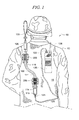
- FIG. 1 shown is a rear perspective view of a portable communication system 50 worn on at least one garment 15 of a user 10, according to one embodiment of the invention.
- the portable communication system 50 includes an antenna assembly 100 that is worn on at least one garment 15 of the user 10.
- the at least one garment 15 on which the portable communication system 50 can be worn includes shirts, belts, trousers, and vests or any other garment known to one of ordinary skill in the art.
- the garment 15 is a vest wherein the portable communication system 50 is mounted to be carried by the user 10.
- the vest 15 could be of the type commonly worn by a soldier containing body armor for protecting the upper body of the soldier from impact from projectiles or the like.
- the portable communication system 50 can include a portable communication device 125 such as a portable radio that can also be worn on the garment 15 of the user 10.
- the portable communication device 125 could be a portable radio such as the Harris Corporation Model RF-5800V-HH radio that is a small, lightweight VHF handheld radio offered by Harris RF Communications Division of Rochester, N.Y.
- the Model RF-5800V-HH radio operates over a broad frequency range of 30-108MHz.
- the invention is not limited in this regard as other portable communication devices could be used as is known to one of ordinary skill in the art.
- the portable communication device 125 could be conventionally equipped with a "rubber duck” or “whip antenna” 126 as a primary antenna as is known in the art. However, as previously discussed, such antennas are limited in their longer range communication ability.
- the antenna assembly 100 can be coupled to an auxiliary connector (not shown) if so equipped on the portable communication device 125 for longer range communication ability. Alternately, if no auxiliary connector is provided, the antenna assembly 100 could be coupled to the connector provided for the rubber duck antenna or whip antenna 126.
- the antenna assembly 100 can be worn on the garment 15 of the user 10 to eliminate the problem of having to carry a portable communication device 125 in a rear pack because of the otherwise unwieldy antenna assembly 100 with a conventional blade antenna. This arrangement also allows the portable communication device 125 to be worn on the front of the garment 15 of the user 10 where it is more convenient to operate.
- the antenna assembly 100 includes a first dipole element 105, a flexible body portion or electrically conductive sleeve 110 also serving as a second dipole element, a dipole feed matching network 106 coupled to the first dipole element 105 and the electrically conductive sleeve 110, and a transmission line 111 extending from the dipole feed matching network 106.
- the electrically conductive sleeve 110 surrounds the transmission line 111 which is coupled to a noise filter 114 adjacent the lower end of the electrically conductive sleeve 110.
- the noise filter 114 reduces interfering noise delivered from the antenna assembly 100 to the receiver in the portable communications device 125.
- a connector 115 disposed on the noise filter 114 for coupling to a first connector 121 on one end of the coaxial cable 120.
- a second connector 122 on the opposite end of the coaxial cable 120 for coupling to a connector (not shown) on the portable communication device 125.
- the first dipole element 105 could be formed of a series of progressively longer strip-shaped conductors to provide flexibility to the first dipole element 105 as will be appreciated by those skilled in the art. Accordingly, the first dipole element 105 may be folded for storage and transportation, but when released will spring to the fully extended position. In the embodiment shown in FIG. 1 , the first dipole element 105 is shown in a folded configuration. For the VHF range described above, the first dipole element 105 may have a length of about thirty-six inches. However, the invention is not limited in this regard.
- a nearly identical antenna assembly 100 is disclosed in the commonly owned U.S. patent no. 6,940,462 to Packer which is incorporated by reference as if fully rewritten herein. It should be understood that the antenna assembly 100 is one possible configuration of an antenna assembly that could be worn on at least one garment 15 of the user 10. However, there are many possible configurations of an antenna assembly 100 possible as is known to one of ordinary skill in the art.
- the antenna assembly 100 is mounted to the garment 15 using at least one user-worn antenna fastening device 200.
- the invention is not limited in this regard as any number of user-worn antenna fastening devices 200 could be used and mounted in any location on the garment 15 of the user 10.
- the user-worn antenna fastening devices are formed of a dielectric material so as to minimize any interaction with the operation of the antenna. Still, the invention is not limited in this regard and the user-worn antenna fastening device could also be formed of metal or any other material.
- the invention is not limited to using the user-worn antenna fastening device 200 on the clothing or garment 15 of the user 10.
- the antenna fastening device 200 could be mounted on a surface such as vehicle panel for mounting the antenna assembly 100 in a vehicle.
- the invention is not limited in this regard as the antenna fastening device 200 could be used to mount the antenna assembly 100 in any desired location as is known to one of ordinary skill in the art.
- the at least one user-worn antenna fastening device 200 is configured for easily and quickly mounting and de-mounting of the antenna assembly 100 to the garment 15.
- the at least one user-worn antenna fastening device 200 is configured for releasably securing a segment 110a ( FIGS. 2-5 ) of the flexible antenna body portion 110 of the antenna assembly 100.
- the at least one user-worn antenna fastening device 200 is configured for releasably securing a segment 110a ( FIGS. 2-5 ) of the flexible antenna body portion 110 in a quick disconnect fashion. This gives the user 10 more flexibility in using the antenna assembly 100.
- the user 10 could sometimes wish to remove the antenna assembly 100 and raise it to a higher position, for example, for better range.
- the at least one user-worn antenna fastening device 200 also is configured for releasing the secured segment 110a ( FIGS. 2-5 ) of the flexible antenna body portion 110 of the antenna assembly 100 in the event a portion of the antenna assembly 100 becomes snagged, for example, on a tree branch. Without the quick disconnect feature, the snagged antenna assembly 100 could cause the user 10 to possibly be in a situation where the user's 10 movement is restricted and unable to free him or herself. This could put the user 10 at great risk.
- the user 10 can release one or more secured segments 110a portions of the antenna assembly 100 from the respective user-worn antenna fastening device 200 by pulling on or applying sufficient force to the segment 110a.
- the antenna assembly can be untangled from the object in which it has become ensnared.
- one or more of the at least one user-worn antenna fastening devices 200 will automatically release the secured segments 110a of the antenna assembly 100.
- the foregoing segments 110a of the antenna assembly 100 can again be releasably secured to the at least one user-worn antenna fastening device 200.
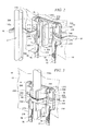
- a segment 110a of the flexible antenna body portion 110 is aligned with and urged into an elongated channel 211 defined by an elongated receiver portion 210 of the at least one user-worn antenna fastening device 200.
- the segment 110a of the flexible antenna body portion 110 is held securely in the channel 211 until pulled on with enough force to overcome the securing force of the elongated receiver portion 210.
- the operation of the mounting and de-mounting of the segment 110a of the flexible antenna body portion 110 in the elongated receiver portion 210 is described in more detail below.
- the mounting of the at least one user-worn antenna fastening device 200 to the garment 15 of the user 10 is detailed below.
- the user-worn antenna fastening device 200 includes a body portion 205 and an elongated receiver portion 210 mounted thereon.
- the body portion 205 includes a plurality of apertures and/or slots for attaching the body portion 205 to a surface such as the surface 15' of garment 15.
- the plurality of apertures and/or slots defined in body portion 205 provide for maximum versatility in attaching body portion 205 to a surface 15'.
- elongated slots 235 are provided on opposing sides of the elongated receiver portion 210 along a first edge 206 of the body portion 205.
- Elongated slots 230 are similarly provided on opposing sides of the elongated receiver portion 210 along a second edge 207 of the body portion 205.
- a pair of apertures 240 are provided adjacent a third and fourth edge 208, 209 of the body portion 205 on opposing sides of the elongated receiver portion 210.
- FIG. 2 and FIGS. 3-5 below a cutaway portion of the garment 15 with a surface 15' is shown in phantom for illustrative purposes corresponding to the embodiment of the invention in FIG. 1 .
- the body portion 205 can be attached to a surface 15' such as the portion of garment 15 shown using a mounting means.
- the mounting means can include a first pair of straps 76, 77 that thread through the horizontally slotted apertures 235.
- a horizontal loop 16 (best seen in FIG. 4 ) is advantageously provided on the surface 15' of the garment 15.
- the horizontal loop 16 can formed of fabric and attached to the surface 15' of the garment 15 by means such as sewing or other means known to one of ordinary skill in the art.
- the straps 76, 77 are connected to and extend from a strap central portion 75 that mounts behind the body portion 205.
- the first pair of straps 76, 77 and the second pair of straps 78, 79 and the strap central portion 75 can be formed from a suitable material such as fabric or other material known to one of ordinary skill in the art.
- the second pair of straps 78, 79 thread through respective horizontally slotted apertures 230 before attaching at the distal ends to the respective distal ends of the straps 76, 77.
- the distal ends of the straps 76, 77 and respective distal ends 78, 79 are preferably attached using conventional hook and loop fasteners disposed thereon.
- the entire surface of one side of the straps 76, 77 and 78, 79 may include hook and loop material for interconnecting the straps 76, 77 to the straps 78, 79.
- the third pair of straps 80, 81 is connected to and extends from the strap central portion 75.
- the third pair of straps 80, 81 is threaded through the vertically slotted apertures 245, 245.
- the free end of a first strap 81 of the third pair of straps 80, 81 is threaded through a first slot 218 defined in first elongated undulation 216.
- the free end of the first strap 81 is further threaded through a second slot 217 defined in a second elongated undulation 215.
- the free end of the first strap 81 is pulled taught through both of the first and second slots 217, 218 before being folded back over second elongated undulation 215, elongated opening 212, and first elongated undulation 216.
- first strap 81 is then secured to a portion of first strap 81 between first elongated undulation 216 and body portion 205.
- hook and loop fastening material is disposed on both the front and rear surfaces of first strap 81 for securing the free end of first strap 81 to the portion of first strap 81 between first elongated undulation 216 and body portion 205.
- first strap 81 taught through both of first and second slots 217, 218 with enough force to compress elongated undulations 215, 216 further secures segment 110a in elongated channel 211 defined by elongated receiver portion 210.
- the normal compressive forces of the elongated undulations 215, 216 may not be enough to prevent segment 110a in elongated channel 211 from slipping up and down when the soldier is running, for example.
- the segment 110a could rotate in the elongated channel 211.
- first strap 81 The additional compressive forces placed on the segment 110a by undulations 215, 216 provided by first strap 81 prevents segment 110a from slipping or rotating. Further, the use of first strap 81 hooked to itself allows for quick disconnect in the event that there is a potential for the antenna assembly 100 to become entangled in a tree branch.
- a second strap 80 from the third pair of straps 80, 81 can then be brought over the top of elongated undulations 215, 216, elongated opening 212, and segment 110a for further securing segment 110a in elongated channel 211 for a tighter fit.
- the rear surface of second strap 80 is provided with hook and loop material for securing the rear surface of second strap 80 to hook and loop material on the surface of first strap 81.
- the means for attaching the body portion 205 to the surface 15' of the garment 15 includes using a pair of conventional metal clips.
- slide keepers which are commonly referred to as ALICE clips, are right-angled "U" shapes members formed of steel with a sliding flat steel piece. When in their closed configuration this type of metal clips forms a rectangle.
- the metal clips (not shown) can be threaded through the horizontal apertures 235 adjacent the first edge 206 of the body portion 205 and the loop 16 on the garment. After the metal clips (not shown) are threaded through the horizontally threaded apertures 235 the sliding portion of the metal clips (not shown) can be moved to the closed position securing the body portion 205 to the loop 16 on the garment 15.
- the means for attaching the body portion to the surface 15' of garment 15 includes using a conventional carabineer clip (not shown).
- a carabineer clip is a metal loop with a spring biased link portion. Carabineer clips are commonly used to quickly and reversibly connect components to other objects.
- the metal loop of the carabineer clip can be threaded through the pair of apertures 240 disposed adjacent to the third and fourth edges 208, 209 of the body portion 205 and the loop 16 on the garment 15.
- the spring biased link (not shown) on the carabineer clip (not shown) automatically moves to the closed position after the carabineer clip (not shown) is threaded through the apertures 240, 240 and the loop 16 for securing the body portion 205 to the loop 16.
- any other means can be used for attaching the body portion 205 to the surface 15' of the garment 15 using any known military or other fastening technology known to one of ordinary skill in the art.
- the segment 110a of the flexible antenna body portion 110 is inserted into the elongated receiver portion 210 by aligning the elongated axis of the segment 110a with an elongated opening 212 of the elongated receiver portion 210.
- the elongated opening 212 is defined by at least one resilient or elongated undulation.
- the at least one undulation is a pair of opposing resilient undulations 215, 216 on the elongated receiver portion 210.
- the elongated opening has a first width of a predetermined width.
- the resilient undulations 215, 216 serve to guide the segment 110a of the flexible antenna body portion 110 in the direction of arrow 300 through the elongated opening 212.
- the resilient undulations 215, 216 also serve to permit the elongated opening 212 to widen to a second width of a predetermined width as the larger diameter segment 110a is urged into an elongated channel 211 defined in the elongated receiver portion 210.
- the larger diameter segment 110a is of a predetermined diameter corresponding to the selected predetermined diameter of the elongated channel 211 as described below.
- a force F applied by the user 10 on the segment 110a urges the segment 110a in the direction of arrow 300 towards the elongated opening 212.
- the force applied to the segment 110a causes a movement of the resilient undulations 215, 216 as the segment 110a of the flexible antenna body portion 110 is urged through the elongated opening 212 as shown by arrows 305, 306, respectively.
- the resilient undulations 215, 216 return to their normal positions thereby securing the segment 110a in the elongated channel 211 of the elongated receiver portion 210.
- the elongated channel 211 is of circular cross-section (best seen in FIG. 5 ) having a predetermined diameter substantially equal to or slightly less than the diameter of the segment 110a of the flexible antenna body portion 110 secured therein. This applies a securing force to segment 110a by the sidewalls defining the elongated channel 211 of the elongated receiver portion 210 as the resilient undulations 215, 216 return to their normal positions.
- the resilient undulations 215, 216, and the elongated channel 211 of the elongated receiver portion 210 apply a securing force to the segment 110a and hold the segment 110a until a force larger than the securing force is applied to the segment 110a in the direction opposite of arrow 300. If a force larger than the securing force is applied to the segment 110a, the segment 110a will be automatically released from the elongated channel 211 of the elongated receiver portion 210.
- FIG. 5 shown is a top view of the user-worn antenna fastening device 200 attached to a surface 15' of the vest 15 of the foregoing figures.
- FIG. 5 is useful for understanding the process for releasably securing a flexible antenna body portion 110 of the antenna assembly 100 to a surface 15'.
- a segment 110a' (shown in phantom for illustrative purposes) is aligned with an elongated opening 212 of the elongated receiver portion 210.
- a force F is placed onto the segment 110a' by the user 10 for urging the segment 110a' in the direction of arrow 300 towards the elongated opening 212.
- the resilient undulations 215, 216 serve to guide the segment 110a' of the flexible antenna body portion 110 through the elongated opening 212.
- the resilient undulations 215, 216 also serve to urge the elongated opening 212 to widen to a second width as the larger diameter segment 110a' is urged into the elongated channel 211 defined in the elongated receiver portion 210.
- the movement of the resilient undulations 215, 216 as the segment 110a' of the flexible antenna body portion 110 is urged through the elongated opening 212 is shown by arrows 305, 306, respectively.
- the resilient undulations 215, 216 return to their normal positions thereby securing the segment 110a in the elongated channel 211 of the elongated receiver portion 210.
- the free end of strap 81 could be threaded through first and second slots 217, 218 in resilient undulations 215, 216 and then secured back onto itself for further securing segment 110a in elongated channel 211.
- the strap 80 can then be brought over the top of resilient undulations 215, 216, elongated opening 212, and segment 110a for further securing segment 110a in elongated channel 211 for a tighter fit.
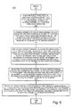
- FIG. 6 shown is a flow diagram of one embodiment of a method 400 of mounting an antenna assembly 100 for a portable communications system 50 to at least one garment 15 of a user 10.
- the method begins with step 401 and continues with step 402.
- a body portion 205 of a user-worn antenna fastening device such as a fastening device 200 is mounted to at least one garment 15 of the user 10 using a mounting means.
- the mounting means could be selected to be a plurality of straps using hook and loop fasteners, a pair of ALICE clips, or a carabineer clip that threads through slotted or other apertures on the body portion and a loop 16 on the surface 15' of the garment 15.
- the mounting means can include any other military or other fastening technology known to one of ordinary skill in the art.
- the at least one garment 15 can be selected to be a shirt, pants, belt, or vest.
- a segment 110a of the antenna assembly 100 is aligned with an elongated opening 212 defined in a receiver portion 210 defined on the body portion 205.
- the elongated opening 212 is of a predetermined first width that opens into an elongated channel 211.
- the elongated channel 211 is configured for receiving and releasably securing the segment 110a of the antenna assembly 100.
- step 404 the segment 110a is urged through the elongated opening 212 guided by at least one resilient undulation into the elongated channel 211.
- the step also includes applying a force to the resilient undulation.
- the force upon the resilient undulation causes the elongated opening 212 to widen to a predetermined second width as the segment 110a is urged through the elongated opening 212.
- the step also includes the resilient undulation returning to a normal position after the segment 110a has moved through the elongated opening 212 and applying a securing force to the segment 110a in the elongated channel 211.
- the method can include the step of selecting the resilient undulation to be a pair of resilient undulations 215, 216 defining the elongated opening 212.
- the elongated channel 211 is selected to have a predetermined diameter that is substantially equal to or less than a diameter of the segment 110a.
- the substantially equal or less diameter is configured for applying an additional securing force to the segment 110a in the elongated channel 211.
- the resilient undulation and the elongated channel 211 are configured for automatically releasing the segment 110a when a force sufficient to overcome the securing force is applied to the segment 110a.
- a free end of a first strap 81 from a third pair of straps 80, 81 is threaded through a first slot 218 defined in a first resilient undulation 216.
- the third pair of straps 80, 81 is threaded through vertically slotted apertures 245, 245 in body portion 205.
- the free end of the first strap 81 is further threaded through a second slot 217 defined in a second resilient undulation 215.
- the free end of the first strap 81 is folded back over second resilient undulation 215, elongated opening 212, and first resilient undulation 216.
- the first strap 81 is pulled taught through both of the first and second slots 217, 218 before being secured to a portion of first strap 81 between first resilient undulation 216 and body portion 205.
- hook and loop fastening material is disposed on both the front and rear surfaces of first strap 81 for securing the free end of first strap 81 to the portion of first strap 81 between first resilient undulation 216 and body portion 205.
- a second strap 80 from the third pair of straps 80, 81 can then be brought over resilient undulations 215, 216, elongated opening 212, and segment 1 10a for further securing segment 110a in elongated channel 211 for a tighter fit.
- the rear surface of second strap 80 is provided with hook and loop material for securing the rear surface of second strap 80 to hook and loop material on the surface of first strap 81.
- the method ends at step 407.
Landscapes
- Engineering & Computer Science (AREA)
- Computer Networks & Wireless Communication (AREA)
- Signal Processing (AREA)
- Professional, Industrial, Or Sporting Protective Garments (AREA)
Abstract
Description
- The invention relates to the field of communications. More particularly, this invention relates to a fastening device and related method of use for releasably securing an antenna assembly for a portable communications device carried by the user to at least one garment of the user.
- It is known to use portable communication devices such as portable radios for communication between personnel such as policemen, firemen, security guards, and soldiers. Such portable radios have included manpack radios which are bulky and typically include a relatively large antenna. More recent advancements in radio communications technology have yielded much smaller portable radio communication devices known as handheld radios. These portable radio communication devices are convenient but generally limited in longer range communication ability. This limitation is due in part to the poor efficiency associated with the conventional type of antenna which is typically coupled thereto. In particular, conventional handheld radios commonly make use of a short flexible rubber coated antenna known as a "rubber duck" antenna or "whip" antenna. These antennas are usually vertical monopole designs which are made relatively short in length by means of electrical loading.
- In order to achieve greater range, some portable radios have been designed to couple to a conventional blade antenna. The problem remains though that the conventional blade antenna is relatively large as compared to the "rubber duck" or "whip" antenna. Consequently, there have been attempts to removably attach a blade antenna to the clothing of the user. The portable radio may also be removably attached to the clothing of the user. Together the antenna and the portable communication device define a portable communication system.
- For example, in
U.S. patent no. 6,940,462 to Packer there is a broadband dipole antenna that is removably fastened to a garment of the user by at least one fastener to define an antenna assembly. The antenna assembly is coupled to a portable radio also carried by the user. The at least one fastener may include a pair of fasteners adjacent opposing ends of the electrically conductive sleeve of the antenna. Each fastener may include a metal clip to connect the fastener to the garment of the user, a clip mounting bracket, and a quick release knob carried by the mounting bracket. However, this arrangement has been considered bulky, heavy, expensive to manufacture, overly complicated to operate and generally unsatisfactory. - In addition to the foregoing, other devices have been used to removably attach antenna assemblies to a garment of the user. Such devices have included Molle type clips, hook and loop fasteners, carabineer clips, and ALICE clips or a combination thereof of these fasteners. However, these devices have also been considered to be unsatisfactory for one or more of the foregoing reasons.
- In view of the foregoing, there remains a need for a device for releasably securing an antenna assembly to the garment of a user for use with a portable communication device that is simple, effective, thin and lightweight, inexpensive to manufacture, and compatible with all military fastening technology.
- In one embodiment of the invention, the invention relates to a user-worn antenna fastening device for releasably securing an antenna assembly to a surface. The user-worn antenna fastening device comprises a body portion, an elongated receiver portion defined on the body portion, and an elongated opening defined in the elongated receiver portion. The elongated opening opens into an elongated channel configured for receiving and releasably securing a segment of the antenna assembly.
- There is at least one resilient undulation defining the elongated opening. The resilient undulation is configured for guiding the segment through the elongated opening into the elongated channel. The resilient undulation is also configured for widening the elongated opening from a predetermined first width to a predetermined second width as the segment is urged through the elongated opening. The first width is less than the diameter of the segment and the second width is equal to the diameter of the segment. The resilient undulation returns to a normal position after the segment has moved through the elongated opening. The at least one resilient undulation applies a securing force to the segment in the elongated channel. In one embodiment of the invention, the resilient undulation is a pair of resilient undulations defining the elongated opening.
- The elongated channel has a predetermined diameter that is substantially equal to or less than the diameter of the segment. The substantially equal or less diameter of the segment is configured for applying an additional securing force to the segment in the elongated channel. The resilient undulation and the elongated channel are configured for automatically releasing the segment when a force sufficient to overcome the securing force is applied to segment.
- There is a means for attaching the body portion to a surface. The means for attaching the body portion to the surface includes using a plurality of straps having hook and loop fasteners on the distal ends. The body portion includes horizontally slotted apertures disposed adjacent first and second edges on opposing sides of said elongated receiver portion for mounting the body portion on the surface. The body portion also includes vertically slotted apertures disposed adjacent third and fourth edges on opposing sides of the elongated receiver portion for receiving a pair of straps for further releasably securing a segment of the antenna assembly.
- A first pair of the straps is threaded through the horizontally slotted apertures adjacent a first edge of the body portion and a loop on the surface. A second pair of the straps is threaded through the horizontally slotted apertures adjacent the second edge of the body portion. The ends of the first pair of straps are fastened to respective ends of second pair of straps using the hook and loop fasteners.
- There is a third pair of straps threaded through the vertically slotted apertures adjacent the third and fourth sides of the body portion for further securing the segment in the elongated channel of the receiver portion. A first one of the straps is threaded through a first slot defined in a first resilient undulation and a second slot defined in the second resilient undulation. The first strap is folded back over the resilient undulations and pulled taught to compress the resilient undulations. The first strap is secured to itself with hook and loop fasteners disposed on both sides of the strap. The first strap is pulled taught with enough force to compress the resilient undulations to further secure the segment of the antenna assembly in the elongated channel. Alternately, a second one of the straps is brought over the resilient undulations and the segment to further secure the segment in the elongated channel. The second strap is secured to the first strap using hook and loop material disposed on the respective surfaces of the straps.
- In another embodiment of the invention, the means for attaching the body portion to the garment includes using one or more ALICE clips threaded through the horizontally threaded apertures adjacent the first edge of the body portion and the loop on the garment. After the ALICE clips are threaded through the horizontally threaded apertures adjacent the first edge of the body portion and the loop on the garment, the sliding portion of the ALICE clips are moved to the closed position securing the body portion to the loop on the garment.
- In another embodiment of the invention, the means for attaching the body portion to the garment includes using a Carabineer clip threaded through a pair of apertures disposed adjacent to the third and fourth edges of the body portion and the loop on the garment. The spring biased link on the Carabineer clip automatically moves to the closed position after the clip is threaded through the apertures and the loop for securing the body portion to the loop.
- In one embodiment of the invention, the surface is on a garment worn by a user of a portable communications system comprising the antenna assembly and a portable communication device. In another embodiment of the invention, the surface is disposed in another location such as in a vehicle.
- In another embodiment of the invention, there is a fastening or quick-disconnect device for releasably securing an antenna assembly to at least one garment of a user of a portable communications device coupled to the antenna assembly. The at least one garment is selected to be a shirt, pants, belt, or vest.
- The user-worn antenna fastening device comprises a body portion, an elongated receiver portion defined on the body portion, and an elongated opening defined in the elongated receiver portion that opens into an elongated channel portion. The elongated channel portion is configured for receiving and releasably securing a segment of the antenna assembly.
- There is at least one resilient undulation defining the elongated opening for guiding the segment through the elongated opening into the elongated channel. The resilient undulation is configured for urging the elongated opening to widen from a predetermined first width to a predetermined second width as the segment is urged through the elongated opening. The first width is less than the diameter of the segment and the second width is equal to the diameter of the segment. The resilient undulation returns to a normal position after the segment has moved through the elongated opening and applies a securing force to the segment in the elongated channel. In one embodiment of the invention, the resilient undulation is a pair of resilient undulations defining the elongated opening.
- The elongated channel has a predetermined diameter that is substantially equal to or less than the diameter of the segment. The elongated channel is configured for applying an additional securing force to the segment in the elongated channel. The resilient undulation and the elongated channel are configured for automatically releasing the segment when a force sufficient to overcome the securing force is applied to segment.
- There is a means for attaching the body portion to the garment. The means for attaching the body portion to the surface includes using a plurality of straps having hook and loop fasteners on the distal ends. The body portion includes horizontally slotted apertures disposed adjacent first and second edges on opposing sides of said elongated receiver portion for mounting the body portion on the surface. The body portion also includes vertically slotted apertures disposed adjacent third and fourth edges on opposing sides of the elongated receiver portion for receiving a pair of straps for further releasably securing a segment of the antenna assembly.
- A first pair of the straps is threaded through the horizontally slotted apertures adjacent a first edge of the body portion and a loop on the surface of the garment. A second pair of the straps is threaded through the horizontally slotted apertures adjacent the second edge of the body portion. The ends of the first pair of straps are fastened to respective ends of second pair of straps using the hook and loop fasteners.
- There is a third pair of straps threaded through the vertically slotted apertures adjacent the third and fourth edges of the body portion for further securing the segment in the elongated channel of the receiver portion. A first one of the straps is threaded through a first slot defined in a first resilient undulation and a second slot defined in a second resilient undulation. The first strap is pulled taught and folded back over the resilient undulations and secured to itself with hook and loop fasteners disposed on both sides of the first strap. The first strap is pulled taught with enough force to compress the resilient undulations to further secure the segment of the antenna assembly in the elongated channel. Alternately, a second one of the straps is brought over the resilient undulations and the segment to further secure the segment in the elongated channel. The second strap is secured to the first strap using hook and loop material disposed on the respective surfaces of the straps.
- In another embodiment of the invention, the means for attaching the body portion to the garment includes using one or more ALICE clips threaded through the horizontally threaded apertures adjacent the first edge of the body portion and the loop on the garment. After the ALICE clips are threaded through the horizontally threaded apertures adjacent the first edge of the body portion and the loop on the garment, the sliding portion of the ALICE clips are moved to the closed position securing the body portion to the loop on the garment.
- In another embodiment of the invention, the means for attaching the body portion to the garment includes using a Carabineer clip threaded through a pair of apertures disposed adjacent to the third and fourth edges of the body portion and the loop on the garment. The spring biased link on the Carabineer clip automatically moves to the closed position after the clip is threaded through the apertures and the loop for securing the body portion to the loop.
- In another embodiment of the invention, there is a method of using at least one quick-disconnect device for releasably securing an antenna assembly to at least one garment of a user of a portable communication system. The method includes the step of mounting a body portion of the fastening device to the garment with a mounting means. The mounting means is selected to be fabric straps using hook and loop fasteners, slide keeper clips, or a carabineer clip. The method includes the further step of selecting the garment to be a shirt, pants, belt, or vest.
- The method includes the step of aligning a segment of the antenna assembly with an elongated opening defined in an elongated receiver portion defined on the body portion. The method includes the step of urging the segment through the elongated opening into the elongated channel guided by at least one resilient undulation. The method includes the further step of selecting the resilient undulation to be a pair of resilient undulations defining the elongated opening.
- The method includes the step of the resilient undulation urging the elongated opening to widen from a predetermined first width to a predetermined second width as the segment is urged through the elongated opening.
- The method includes the step of the resilient undulation returning to a normal position after the segment has moved through the elongated opening and applies a securing force to the segment in the elongated channel. The elongated opening opens into an elongated channel configured for receiving and releasably securing a segment of the antenna assembly.
- The method includes the step of selecting the elongated channel to have a predetermined diameter that is substantially equal to or less than the diameter of the segment. The elongated channel is configured for applying an additional securing force to the segment.
- The method includes the step of configuring the resilient undulation and the elongated channel for automatically releasing the segment when a force sufficient to overcome the securing force is applied to the segment.
- The method includes the step of threading a free end of a first strap from a third pair of straps through a first slot defined in a first resilient undulation. The third pair of straps is threaded through vertically slotted apertures in the body portion. The free end of the first strap is further threaded through a second slot defined in a second resilient undulation. The free end of the first strap is folded back over the front of the resilient undulations and the elongated opening and pulled taught to compress the resilient undulations. The free end of the first strap is then secured back onto a portion of the first strap between the first resilient undulation and the body portion. In this regard, hook and loop fastening material is disposed on both the front and rear surfaces of the first strap for securing the free end of the first strap onto the portion of the first strap between the first resilient undulation and the body portion.
- Alternately, a second strap from the third pair of straps is brought over the resilient undulations, the elongated opening, and the segment for further securing the segment in the elongated channel for a tighter fit. The rear surface of the second strap is provided with hook and loop material for securing the rear surface of the second strap to hook and loop material on the surface of the first strap.
- Embodiments will be described with reference to the following drawing figures, in which like numerals represent like items throughout the figures, and in which:
-
FIG. 1 is rear view of a user wearing a portable communication system comprising an antenna assembly and portable communication device which is useful for understanding an embodiment of the invention; -
FIG. 2 is an enlarged perspective view of a user-worn antenna fastening device of the communication system ofFIG. 1 attached to a portion of the user's garment for showing the insertion of a segment of the antenna assembly into an elongated receiver portion; -
FIG. 3 is an enlarged perspective view of the user-worn antenna fastening device inFIG. 2 showing a segment of the antenna assembly releasably secured in the elongated receiver portion; -
FIG. 4 is a right side view of the user-worn antenna fastening device ofFIG. 3 attached to a portion of the user's garment and showing the segment of the antenna assembly releasably secured in an elongated receiver portion of the device; -
FIG. 5 is a top view of the user-worn antenna fastening device ofFIG. 2 mounted on a portion of the user's garment with a segment of the antenna assembly releasably secured in the elongated receiver portion; and -
FIG. 6 is a flow diagram of one embodiment of a method of using a device for releasably securing an antenna assembly of portable communication system to at least one garment of a user. - Referring now to
FIG. 1 , shown is a rear perspective view of aportable communication system 50 worn on at least onegarment 15 of auser 10, according to one embodiment of the invention. Theportable communication system 50 includes anantenna assembly 100 that is worn on at least onegarment 15 of theuser 10. The at least onegarment 15 on which theportable communication system 50 can be worn includes shirts, belts, trousers, and vests or any other garment known to one of ordinary skill in the art. In the embodiment shown inFIG. 1 , thegarment 15 is a vest wherein theportable communication system 50 is mounted to be carried by theuser 10. Thevest 15 could be of the type commonly worn by a soldier containing body armor for protecting the upper body of the soldier from impact from projectiles or the like. - The
portable communication system 50 can include aportable communication device 125 such as a portable radio that can also be worn on thegarment 15 of theuser 10. For example, theportable communication device 125 could be a portable radio such as the Harris Corporation Model RF-5800V-HH radio that is a small, lightweight VHF handheld radio offered by Harris RF Communications Division of Rochester, N.Y. The Model RF-5800V-HH radio operates over a broad frequency range of 30-108MHz. However, the invention is not limited in this regard as other portable communication devices could be used as is known to one of ordinary skill in the art. - The
portable communication device 125 could be conventionally equipped with a "rubber duck" or "whip antenna" 126 as a primary antenna as is known in the art. However, as previously discussed, such antennas are limited in their longer range communication ability. In view of the foregoing, theantenna assembly 100 can be coupled to an auxiliary connector (not shown) if so equipped on theportable communication device 125 for longer range communication ability. Alternately, if no auxiliary connector is provided, theantenna assembly 100 could be coupled to the connector provided for the rubber duck antenna orwhip antenna 126. In addition, theantenna assembly 100 can be worn on thegarment 15 of theuser 10 to eliminate the problem of having to carry aportable communication device 125 in a rear pack because of the otherwiseunwieldy antenna assembly 100 with a conventional blade antenna. This arrangement also allows theportable communication device 125 to be worn on the front of thegarment 15 of theuser 10 where it is more convenient to operate. - The
antenna assembly 100 includes afirst dipole element 105, a flexible body portion or electricallyconductive sleeve 110 also serving as a second dipole element, a dipolefeed matching network 106 coupled to thefirst dipole element 105 and the electricallyconductive sleeve 110, and atransmission line 111 extending from the dipolefeed matching network 106. The electricallyconductive sleeve 110 surrounds thetransmission line 111 which is coupled to anoise filter 114 adjacent the lower end of the electricallyconductive sleeve 110. Thenoise filter 114 reduces interfering noise delivered from theantenna assembly 100 to the receiver in theportable communications device 125. There is aconnector 115 disposed on thenoise filter 114 for coupling to afirst connector 121 on one end of thecoaxial cable 120. There is asecond connector 122 on the opposite end of thecoaxial cable 120 for coupling to a connector (not shown) on theportable communication device 125. - The
first dipole element 105 could be formed of a series of progressively longer strip-shaped conductors to provide flexibility to thefirst dipole element 105 as will be appreciated by those skilled in the art. Accordingly, thefirst dipole element 105 may be folded for storage and transportation, but when released will spring to the fully extended position. In the embodiment shown inFIG. 1 , thefirst dipole element 105 is shown in a folded configuration. For the VHF range described above, thefirst dipole element 105 may have a length of about thirty-six inches. However, the invention is not limited in this regard. - A nearly
identical antenna assembly 100 is disclosed in the commonly ownedU.S. patent no. 6,940,462 to Packer which is incorporated by reference as if fully rewritten herein. It should be understood that theantenna assembly 100 is one possible configuration of an antenna assembly that could be worn on at least onegarment 15 of theuser 10. However, there are many possible configurations of anantenna assembly 100 possible as is known to one of ordinary skill in the art. - The
antenna assembly 100 is mounted to thegarment 15 using at least one user-wornantenna fastening device 200. In the embodiment shown inFIG. 1 , there is an upper user-wornantenna fastening device 200 mounted ongarment 15 near the left shoulder of theuser 10 and a lower user-wornantenna fastening device 200 mounted centrally on thegarment 15 above the waist of theuser 10. However, the invention is not limited in this regard as any number of user-wornantenna fastening devices 200 could be used and mounted in any location on thegarment 15 of theuser 10. According to a preferred embodiment, the user-worn antenna fastening devices are formed of a dielectric material so as to minimize any interaction with the operation of the antenna. Still, the invention is not limited in this regard and the user-worn antenna fastening device could also be formed of metal or any other material. - In addition, the invention is not limited to using the user-worn
antenna fastening device 200 on the clothing orgarment 15 of theuser 10. In another embodiment of the invention (not shown), theantenna fastening device 200 could be mounted on a surface such as vehicle panel for mounting theantenna assembly 100 in a vehicle. Still, the invention is not limited in this regard as theantenna fastening device 200 could be used to mount theantenna assembly 100 in any desired location as is known to one of ordinary skill in the art. - The at least one user-worn
antenna fastening device 200 is configured for easily and quickly mounting and de-mounting of theantenna assembly 100 to thegarment 15. In the embodiment shown inFIG. 1 , the at least one user-wornantenna fastening device 200 is configured for releasably securing asegment 110a (FIGS. 2-5 ) of the flexibleantenna body portion 110 of theantenna assembly 100. The at least one user-wornantenna fastening device 200 is configured for releasably securing asegment 110a (FIGS. 2-5 ) of the flexibleantenna body portion 110 in a quick disconnect fashion. This gives theuser 10 more flexibility in using theantenna assembly 100. - For example, the
user 10 could sometimes wish to remove theantenna assembly 100 and raise it to a higher position, for example, for better range. In addition, the at least one user-wornantenna fastening device 200 also is configured for releasing thesecured segment 110a (FIGS. 2-5 ) of the flexibleantenna body portion 110 of theantenna assembly 100 in the event a portion of theantenna assembly 100 becomes snagged, for example, on a tree branch. Without the quick disconnect feature, the snaggedantenna assembly 100 could cause theuser 10 to possibly be in a situation where the user's 10 movement is restricted and unable to free him or herself. This could put theuser 10 at great risk. - With the quick disconnect feature, the
user 10 can release one or moresecured segments 110a portions of theantenna assembly 100 from the respective user-wornantenna fastening device 200 by pulling on or applying sufficient force to thesegment 110a. Once the portion of theantenna assembly 100 is released from the user-wornantenna fastening device 200, the antenna assembly can be untangled from the object in which it has become ensnared. Alternately, if theuser 10 pulls away from the object with sufficient force, one or more of the at least one user-wornantenna fastening devices 200 will automatically release the securedsegments 110a of theantenna assembly 100. Once free of the object, the foregoingsegments 110a of theantenna assembly 100 can again be releasably secured to the at least one user-wornantenna fastening device 200. This operation is in contrast to prior art user-worn antenna fastening devices which do not automatically release the antenna assembly from the at least one garment of the user if the antenna assembly were to become snagged. Such prior art devices often require manipulating a knob or lever to release the antenna assembly from the at least one user-worn antenna fastening device before attempting to untangle the antenna assembly. - Referring now to
FIGS. 2 and 3 , it can be observed that asegment 110a of the flexibleantenna body portion 110 is aligned with and urged into anelongated channel 211 defined by anelongated receiver portion 210 of the at least one user-wornantenna fastening device 200. Thesegment 110a of the flexibleantenna body portion 110 is held securely in thechannel 211 until pulled on with enough force to overcome the securing force of theelongated receiver portion 210. The operation of the mounting and de-mounting of thesegment 110a of the flexibleantenna body portion 110 in theelongated receiver portion 210 is described in more detail below. In addition, the mounting of the at least one user-wornantenna fastening device 200 to thegarment 15 of theuser 10 is detailed below. - Referring again to
FIGS. 2 and 3 , the user-wornantenna fastening device 200 includes abody portion 205 and anelongated receiver portion 210 mounted thereon. Thebody portion 205 includes a plurality of apertures and/or slots for attaching thebody portion 205 to a surface such as thesurface 15' ofgarment 15. The plurality of apertures and/or slots defined inbody portion 205 provide for maximum versatility in attachingbody portion 205 to asurface 15'. - For example,
elongated slots 235 are provided on opposing sides of theelongated receiver portion 210 along afirst edge 206 of thebody portion 205.Elongated slots 230 are similarly provided on opposing sides of theelongated receiver portion 210 along asecond edge 207 of thebody portion 205. A pair ofapertures 240 are provided adjacent a third andfourth edge body portion 205 on opposing sides of theelongated receiver portion 210. There could be another pair of elongated slots 245 (only one is seen inFIG. 2 and FIG. 3 below) on opposing sides of theelongated receiver portion 210. Any combination of theapertures elongated slots body portion 205 to asurface 15' ofgarment 15. - In
FIG. 2 and FIGS. 3-5 below, a cutaway portion of thegarment 15 with asurface 15' is shown in phantom for illustrative purposes corresponding to the embodiment of the invention inFIG. 1 . Using the foregoingapertures 240 orelongated slots body portion 205 can be attached to asurface 15' such as the portion ofgarment 15 shown using a mounting means. - For example, the mounting means can include a first pair of
straps apertures 235. A horizontal loop 16 (best seen inFIG. 4 ) is advantageously provided on thesurface 15' of thegarment 15. Thehorizontal loop 16 can formed of fabric and attached to thesurface 15' of thegarment 15 by means such as sewing or other means known to one of ordinary skill in the art. Thestraps central portion 75 that mounts behind thebody portion 205. There is a second pair ofstraps strap body portion 75. The first pair ofstraps straps central portion 75 can be formed from a suitable material such as fabric or other material known to one of ordinary skill in the art. - The second pair of
straps apertures 230 before attaching at the distal ends to the respective distal ends of thestraps straps straps straps straps - There could be a third pair of
straps central portion 75. The third pair ofstraps apertures first strap 81 of the third pair ofstraps first slot 218 defined in firstelongated undulation 216. The free end of thefirst strap 81 is further threaded through asecond slot 217 defined in a secondelongated undulation 215. The free end of thefirst strap 81 is pulled taught through both of the first andsecond slots elongated undulation 215,elongated opening 212, and firstelongated undulation 216. The free end offirst strap 81 is then secured to a portion offirst strap 81 between firstelongated undulation 216 andbody portion 205. In this regard, hook and loop fastening material is disposed on both the front and rear surfaces offirst strap 81 for securing the free end offirst strap 81 to the portion offirst strap 81 between firstelongated undulation 216 andbody portion 205. - Pulling
first strap 81 taught through both of first andsecond slots elongated undulations segment 110a inelongated channel 211 defined byelongated receiver portion 210. In this regard, without the additional compressive force of theelongated undulations first strap 81, the normal compressive forces of theelongated undulations segment 110a inelongated channel 211 from slipping up and down when the soldier is running, for example. In addition, if the soldier is laying down on the ground on the stomach with thefirst dipole element 105 bent up 90° for better reception, thesegment 110a could rotate in theelongated channel 211. The additional compressive forces placed on thesegment 110a by undulations 215, 216 provided byfirst strap 81 preventssegment 110a from slipping or rotating. Further, the use offirst strap 81 hooked to itself allows for quick disconnect in the event that there is a potential for theantenna assembly 100 to become entangled in a tree branch. - Alternately, if there is no potential of the
antenna assembly 100 becoming entangled, asecond strap 80 from the third pair ofstraps undulations elongated opening 212, andsegment 110a for further securingsegment 110a inelongated channel 211 for a tighter fit. The rear surface ofsecond strap 80 is provided with hook and loop material for securing the rear surface ofsecond strap 80 to hook and loop material on the surface offirst strap 81. - In another embodiment of the invention, the means for attaching the
body portion 205 to thesurface 15' of thegarment 15 includes using a pair of conventional metal clips. For example slide keepers, which are commonly referred to as ALICE clips, are right-angled "U" shapes members formed of steel with a sliding flat steel piece. When in their closed configuration this type of metal clips forms a rectangle. The metal clips (not shown) can be threaded through thehorizontal apertures 235 adjacent thefirst edge 206 of thebody portion 205 and theloop 16 on the garment. After the metal clips (not shown) are threaded through the horizontally threadedapertures 235 the sliding portion of the metal clips (not shown) can be moved to the closed position securing thebody portion 205 to theloop 16 on thegarment 15. - In another embodiment of the invention, the means for attaching the body portion to the
surface 15' ofgarment 15 includes using a conventional carabineer clip (not shown). A carabineer clip is a metal loop with a spring biased link portion. Carabineer clips are commonly used to quickly and reversibly connect components to other objects. The metal loop of the carabineer clip can be threaded through the pair ofapertures 240 disposed adjacent to the third andfourth edges body portion 205 and theloop 16 on thegarment 15. The spring biased link (not shown) on the carabineer clip (not shown) automatically moves to the closed position after the carabineer clip (not shown) is threaded through theapertures loop 16 for securing thebody portion 205 to theloop 16. - Alternately, any other means can be used for attaching the
body portion 205 to thesurface 15' of thegarment 15 using any known military or other fastening technology known to one of ordinary skill in the art. - Referring once again to
FIG. 2 , it can be observed that thesegment 110a of the flexibleantenna body portion 110 is inserted into theelongated receiver portion 210 by aligning the elongated axis of thesegment 110a with anelongated opening 212 of theelongated receiver portion 210. Theelongated opening 212 is defined by at least one resilient or elongated undulation. In the embodiment of the invention shown, the at least one undulation is a pair of opposingresilient undulations elongated receiver portion 210. The elongated opening has a first width of a predetermined width. Theresilient undulations segment 110a of the flexibleantenna body portion 110 in the direction ofarrow 300 through theelongated opening 212. Theresilient undulations elongated opening 212 to widen to a second width of a predetermined width as thelarger diameter segment 110a is urged into anelongated channel 211 defined in theelongated receiver portion 210. Thelarger diameter segment 110a is of a predetermined diameter corresponding to the selected predetermined diameter of theelongated channel 211 as described below. - In use, a force F applied by the
user 10 on thesegment 110a urges thesegment 110a in the direction ofarrow 300 towards theelongated opening 212. The force applied to thesegment 110a causes a movement of theresilient undulations segment 110a of the flexibleantenna body portion 110 is urged through theelongated opening 212 as shown byarrows - Still referring to
FIG. 2 but now also toFIGS. 3-5 , once thesegment 110a is received in theelongated channel 211, theresilient undulations segment 110a in theelongated channel 211 of theelongated receiver portion 210. Theelongated channel 211 is of circular cross-section (best seen inFIG. 5 ) having a predetermined diameter substantially equal to or slightly less than the diameter of thesegment 110a of the flexibleantenna body portion 110 secured therein. This applies a securing force tosegment 110a by the sidewalls defining theelongated channel 211 of theelongated receiver portion 210 as theresilient undulations - Collectively, the
resilient undulations elongated channel 211 of theelongated receiver portion 210 apply a securing force to thesegment 110a and hold thesegment 110a until a force larger than the securing force is applied to thesegment 110a in the direction opposite ofarrow 300. If a force larger than the securing force is applied to thesegment 110a, thesegment 110a will be automatically released from theelongated channel 211 of theelongated receiver portion 210. - Referring now to
FIG. 5 , shown is a top view of the user-wornantenna fastening device 200 attached to asurface 15' of thevest 15 of the foregoing figures.FIG. 5 is useful for understanding the process for releasably securing a flexibleantenna body portion 110 of theantenna assembly 100 to asurface 15'. As illustrated therein, asegment 110a' (shown in phantom for illustrative purposes) is aligned with anelongated opening 212 of theelongated receiver portion 210. A force F is placed onto thesegment 110a' by theuser 10 for urging thesegment 110a' in the direction ofarrow 300 towards theelongated opening 212. - As noted above, the
resilient undulations segment 110a' of the flexibleantenna body portion 110 through theelongated opening 212. Theresilient undulations elongated opening 212 to widen to a second width as thelarger diameter segment 110a' is urged into theelongated channel 211 defined in theelongated receiver portion 210. The movement of theresilient undulations segment 110a' of the flexibleantenna body portion 110 is urged through theelongated opening 212 is shown byarrows - Once the
segment 110a is seated in theelongated channel 211, theresilient undulations segment 110a in theelongated channel 211 of theelongated receiver portion 210. As previously discussed, the free end ofstrap 81 could be threaded through first andsecond slots resilient undulations segment 110a inelongated channel 211. Thestrap 80 can then be brought over the top ofresilient undulations elongated opening 212, andsegment 110a for further securingsegment 110a inelongated channel 211 for a tighter fit. - Referring now specifically to
FIG. 6 and toFIGS. 1-5 , shown is a flow diagram of one embodiment of amethod 400 of mounting anantenna assembly 100 for aportable communications system 50 to at least onegarment 15 of auser 10. The method begins withstep 401 and continues withstep 402. - In
step 402, abody portion 205 of a user-worn antenna fastening device such as afastening device 200 is mounted to at least onegarment 15 of theuser 10 using a mounting means. The mounting means could be selected to be a plurality of straps using hook and loop fasteners, a pair of ALICE clips, or a carabineer clip that threads through slotted or other apertures on the body portion and aloop 16 on thesurface 15' of thegarment 15. Alternately, the mounting means can include any other military or other fastening technology known to one of ordinary skill in the art. The at least onegarment 15 can be selected to be a shirt, pants, belt, or vest. - In
step 403, asegment 110a of theantenna assembly 100 is aligned with anelongated opening 212 defined in areceiver portion 210 defined on thebody portion 205. Theelongated opening 212 is of a predetermined first width that opens into anelongated channel 211. Theelongated channel 211 is configured for receiving and releasably securing thesegment 110a of theantenna assembly 100. - In
step 404, thesegment 110a is urged through theelongated opening 212 guided by at least one resilient undulation into theelongated channel 211. The step also includes applying a force to the resilient undulation. The force upon the resilient undulation causes theelongated opening 212 to widen to a predetermined second width as thesegment 110a is urged through theelongated opening 212. The step also includes the resilient undulation returning to a normal position after thesegment 110a has moved through theelongated opening 212 and applying a securing force to thesegment 110a in theelongated channel 211. In another embodiment of the invention, the method can include the step of selecting the resilient undulation to be a pair ofresilient undulations elongated opening 212. - In
step 405, theelongated channel 211 is selected to have a predetermined diameter that is substantially equal to or less than a diameter of thesegment 110a. The substantially equal or less diameter is configured for applying an additional securing force to thesegment 110a in theelongated channel 211. The resilient undulation and theelongated channel 211 are configured for automatically releasing thesegment 110a when a force sufficient to overcome the securing force is applied to thesegment 110a. - In
step 406, a free end of afirst strap 81 from a third pair ofstraps first slot 218 defined in a firstresilient undulation 216. The third pair ofstraps apertures body portion 205. The free end of thefirst strap 81 is further threaded through asecond slot 217 defined in a secondresilient undulation 215. The free end of thefirst strap 81 is folded back over secondresilient undulation 215,elongated opening 212, and firstresilient undulation 216. Thefirst strap 81 is pulled taught through both of the first andsecond slots first strap 81 between firstresilient undulation 216 andbody portion 205. In this regard, hook and loop fastening material is disposed on both the front and rear surfaces offirst strap 81 for securing the free end offirst strap 81 to the portion offirst strap 81 between firstresilient undulation 216 andbody portion 205. - Alternately, a
second strap 80 from the third pair ofstraps resilient undulations elongated opening 212, andsegment 1 10a for further securingsegment 110a inelongated channel 211 for a tighter fit. The rear surface ofsecond strap 80 is provided with hook and loop material for securing the rear surface ofsecond strap 80 to hook and loop material on the surface offirst strap 81. - The method ends at
step 407.
Claims (10)
- A user-worn antenna fastening device for releasably securing an antenna assembly to a surface, comprising:a body portion;an elongated receiver portion defined on the body portion;an elongated opening defined in said elongated receiver portion of a predetermined first width that opens into an elongated channel, said elongated channel configured for receiving and releasably securing a segment of the antenna assembly;at least one resilient undulation defining said elongated opening configured for guiding the segment through said elongated opening into said elongated channel, said at least one resilient undulation configured for urging said elongated opening to a predetermined second width as the segment is urged through said elongated opening, and said resilient undulation returning to a normal position after the segment has moved through said elongated opening and applying a securing force to the segment in said elongated channel; andmeans for attaching said body portion to the surface.
- The device of claim 1, wherein said elongated channel has a predetermined diameter that is substantially equal to or less than a diameter of the segment, wherein said elongated channel is configured for applying an additional securing force to the segment in said elongated channel.
- The device of claim 2, wherein said resilient undulation and said elongated channel are configured for automatically releasing the segment when a force sufficient to overcome said securing force is applied to the segment.
- The device of claim 1, wherein said resilient undulation is a pair of resilient undulations defining said elongated opening.
- The device of claim 1, wherein said means for attaching said body portion to the surface is selected from a member of the group consisting of fabric straps using hook and loop fasteners, slide keeper clips, and a carabineer clip.
- The device of claim 1, wherein the surface is on a garment worn by a user of a portable communications system comprising the antenna assembly and a portable communication device.
- A method of using at least one fastening device for releasably securing an antenna assembly to at least one garment of a user of a portable communication system, comprising the steps of:mounting a body portion of the fastening device to the garment with a mounting means;aligning a segment of said antenna assembly with an elongated opening defined in an elongated receiver portion defined on said body portion, said elongated opening being of a predetermined first width that opens into an elongated channel configured for receiving and releasably securing a segment of the antenna assembly; andurging said segment through said elongated opening into said elongated channel guided by at least one resilient undulation, said resilient undulation urging said elongated opening to widen to a predetermined second width as the segment is urged through said elongated opening, and said resilient undulation returning to a normal position after the segment has moved through said elongated opening and applying a securing force to the segment in said elongated channel.
- The method of claim 7, further comprising the step of selecting said elongated channel to have a predetermined diameter that is substantially equal to or less than a diameter of the segment configured for applying an additional securing force to the segment in said elongated channel.
- The method of claim 8, further comprising the step of configuring said resilient undulation and said elongated channel for automatically releasing the segment when a force sufficient to overcome said securing force is applied to the segment.
- The method of claim 7, further comprising the step of selecting said resilient undulation to be a pair of resilient undulations defining said elongated opening.
Applications Claiming Priority (1)
| Application Number | Priority Date | Filing Date | Title |
|---|---|---|---|
| US11/775,965 US7969369B2 (en) | 2007-07-11 | 2007-07-11 | Body-worn antenna fastening device and method |
Publications (1)
| Publication Number | Publication Date |
|---|---|
| EP2015393A1 true EP2015393A1 (en) | 2009-01-14 |
Family
ID=39791495
Family Applications (1)
| Application Number | Title | Priority Date | Filing Date |
|---|---|---|---|
| EP08012388A Withdrawn EP2015393A1 (en) | 2007-07-11 | 2008-07-09 | Body-worn antenna fastening device and method |
Country Status (3)
| Country | Link |
|---|---|
| US (1) | US7969369B2 (en) |
| EP (1) | EP2015393A1 (en) |
| IL (1) | IL192733A0 (en) |
Cited By (1)
| Publication number | Priority date | Publication date | Assignee | Title |
|---|---|---|---|---|
| WO2014102057A1 (en) * | 2012-12-24 | 2014-07-03 | Selex Es Ltd | A collapsible portable antenna |
Families Citing this family (11)
| Publication number | Priority date | Publication date | Assignee | Title |
|---|---|---|---|---|
| US8933851B2 (en) * | 2010-01-27 | 2015-01-13 | Bae Systems Plc | Body wearable antenna |
| US8810463B2 (en) * | 2011-05-06 | 2014-08-19 | Jeffrey B. Kirkham | Antenna mount |
| US9565922B2 (en) | 2011-08-08 | 2017-02-14 | FirstSpear, LLC | Light weight modular pouch attachment system and method |
| US20140306686A1 (en) * | 2013-04-10 | 2014-10-16 | Alan David Haddy | User Mountable Utility Location Antenna |
| US9209514B2 (en) * | 2013-08-09 | 2015-12-08 | Motorola Solutions, Inc. | Body-worn antenna |
| US9343800B2 (en) * | 2013-08-09 | 2016-05-17 | Motorola Solutions, Inc. | Flexible mounting apparatus for mounting an antenna |
| US20160366990A1 (en) * | 2015-06-17 | 2016-12-22 | Rodney Smith | Article of clothing for attaching communication equipment thereto |
| TWD178159S (en) * | 2016-04-01 | 2016-09-11 | 廣達電腦股份有限公司 | Mobile computing device |
| TWD178160S (en) * | 2016-04-18 | 2016-09-11 | 廣達電腦股份有限公司 | Mobile computing device |
| US10868358B2 (en) * | 2017-10-19 | 2020-12-15 | Harris Solutions NY, Inc. | Antenna for wearable radio system and associated method of making |
| US11063345B2 (en) * | 2018-07-17 | 2021-07-13 | Mastodon Design Llc | Systems and methods for providing a wearable antenna |
Citations (8)
| Publication number | Priority date | Publication date | Assignee | Title |
|---|---|---|---|---|
| DE307103C (en) * | ||||
| US2285083A (en) * | 1940-03-30 | 1942-06-02 | Electra Voice Corp | Two-way radio garment |
| CA982672A (en) * | 1973-01-05 | 1976-01-27 | Antennacraft Company | Plastic clip device for mounting an accessory on an antenna boom |
| WO1997008972A1 (en) | 1995-09-01 | 1997-03-13 | Centurion Safety Products, Inc. | Belt-mounted flashlight holder |
| EP1010380A1 (en) | 1998-12-18 | 2000-06-21 | National Molding Corporation | Multi-purpose attachment device |
| US20050017080A1 (en) | 2003-07-21 | 2005-01-27 | Nancy Gold | Special usable pocket |
| EP1517397A1 (en) * | 2003-09-19 | 2005-03-23 | Harris Corporation | Broadband dipole antenna to be worn by a user and associated methods |
| US20050263323A1 (en) * | 2003-11-25 | 2005-12-01 | Research In Motion Limited | Surface mountable clip suitable for use in a mobile communication device |
Family Cites Families (9)
| Publication number | Priority date | Publication date | Assignee | Title |
|---|---|---|---|---|
| US2576128A (en) | 1948-04-03 | 1951-11-27 | Motorola Inc | Man-pack antenna |
| BE568407A (en) | 1956-03-27 | 1958-06-30 | ||
| US3049774A (en) | 1960-09-28 | 1962-08-21 | Rhodes Alex | Clips |
| US3349405A (en) * | 1964-07-22 | 1967-10-24 | Bel Tronics Corp | Antenna mounting article |
| AU7396096A (en) | 1995-10-09 | 1997-04-30 | Precision Tracking, Inc. | Improved gps receivers and garments containing gps receivers and methods for using these gps receivers |
| US6972725B1 (en) * | 2002-01-31 | 2005-12-06 | The United States Of America As Represented By The Secretary Of The Navy | Ultra-broadband antenna incorporated into a garment |
| US6590540B1 (en) | 2002-01-31 | 2003-07-08 | The United States Of America As Represented By The Secretary Of The Navy | Ultra-broadband antenna incorporated into a garment |
| JP2005245937A (en) * | 2004-03-08 | 2005-09-15 | Pentax Corp | Clothing with communication function and endoscope system |
| US7195511B1 (en) | 2006-01-17 | 2007-03-27 | Harris Corporation | Cable strain relief |
-
2007
- 2007-07-11 US US11/775,965 patent/US7969369B2/en active Active
-
2008
- 2008-07-09 IL IL192733A patent/IL192733A0/en unknown
- 2008-07-09 EP EP08012388A patent/EP2015393A1/en not_active Withdrawn
Patent Citations (8)
| Publication number | Priority date | Publication date | Assignee | Title |
|---|---|---|---|---|
| DE307103C (en) * | ||||
| US2285083A (en) * | 1940-03-30 | 1942-06-02 | Electra Voice Corp | Two-way radio garment |
| CA982672A (en) * | 1973-01-05 | 1976-01-27 | Antennacraft Company | Plastic clip device for mounting an accessory on an antenna boom |
| WO1997008972A1 (en) | 1995-09-01 | 1997-03-13 | Centurion Safety Products, Inc. | Belt-mounted flashlight holder |
| EP1010380A1 (en) | 1998-12-18 | 2000-06-21 | National Molding Corporation | Multi-purpose attachment device |
| US20050017080A1 (en) | 2003-07-21 | 2005-01-27 | Nancy Gold | Special usable pocket |
| EP1517397A1 (en) * | 2003-09-19 | 2005-03-23 | Harris Corporation | Broadband dipole antenna to be worn by a user and associated methods |
| US20050263323A1 (en) * | 2003-11-25 | 2005-12-01 | Research In Motion Limited | Surface mountable clip suitable for use in a mobile communication device |
Cited By (4)
| Publication number | Priority date | Publication date | Assignee | Title |
|---|---|---|---|---|
| WO2014102057A1 (en) * | 2012-12-24 | 2014-07-03 | Selex Es Ltd | A collapsible portable antenna |
| US9515374B2 (en) | 2012-12-24 | 2016-12-06 | Leonardo Mw Ltd | Collapsible portable antenna |
| US9634382B2 (en) | 2012-12-24 | 2017-04-25 | Leonardo Mw Ltd. | Portable antenna |
| US9711844B2 (en) | 2012-12-24 | 2017-07-18 | Leonardo Mw Ltd | Portable antenna |
Also Published As
| Publication number | Publication date |
|---|---|
| US20110074644A1 (en) | 2011-03-31 |
| IL192733A0 (en) | 2009-02-11 |
| US7969369B2 (en) | 2011-06-28 |
Similar Documents
| Publication | Publication Date | Title |
|---|---|---|
| US7969369B2 (en) | Body-worn antenna fastening device and method | |
| US12072168B2 (en) | Modular armor supplement apparatus and system with silent fasteners and adjustability | |
| US20190274415A1 (en) | Pouch or holster coupled with a retracting device | |
| EP2248558B1 (en) | Harness for breathing apparatus | |
| CN101535160B (en) | Stick-on security ring for a hand held device | |
| US20140259249A1 (en) | Armor Plate Carrier | |
| US20160100642A1 (en) | Concealed gun belt, holster and magazine holders | |
| US11262161B2 (en) | System and method for attaching, routing and concealing cables on load carrying webbing | |
| US20190154404A1 (en) | Adjustable Ballistic Garment | |
| US20150168097A1 (en) | Single point tactical sling and hands free carrying device | |
| US10791820B2 (en) | Adjustable carrying device | |
| US10638816B2 (en) | Versatile protective outerwear | |
| US9930956B2 (en) | Portable radio retention device | |
| US9714810B1 (en) | Rifle sling | |
| US20150144670A1 (en) | Holders having multiple, adjustable straps | |
| US20140239030A1 (en) | Pack harness | |
| CA2939765C (en) | Quickly releasable vest | |
| US11812844B2 (en) | Multiple magnet connection mechanism for retractors | |
| JP2010021756A (en) | Wearable antenna fastening device and method | |
| US20240353053A1 (en) | Retractor arranged for top mounting | |
| US11805832B2 (en) | Removable expandable semirigid cummerbund | |
| US12385719B2 (en) | Weapon sling with integral connectors for wired communication and/or power transfer | |
| CA3093285A1 (en) | Removable expandable semirigid cummerbund | |
| US20250335003A1 (en) | Head-Mounted Devices with Adjustable Headbands | |
| AU704069B3 (en) | A cellular telephone safety device |
Legal Events
| Date | Code | Title | Description |
|---|---|---|---|
| PUAI | Public reference made under article 153(3) epc to a published international application that has entered the european phase |
Free format text: ORIGINAL CODE: 0009012 |
|
| 17P | Request for examination filed |
Effective date: 20080709 |
|
| AK | Designated contracting states |
Kind code of ref document: A1 Designated state(s): AT BE BG CH CY CZ DE DK EE ES FI FR GB GR HR HU IE IS IT LI LT LU LV MC MT NL NO PL PT RO SE SI SK TR |
|
| AX | Request for extension of the european patent |
Extension state: AL BA MK RS |
|
| AKX | Designation fees paid |
Designated state(s): DE FI FR GB IT NO |
|
| 17Q | First examination report despatched |
Effective date: 20100301 |
|
| STAA | Information on the status of an ep patent application or granted ep patent |
Free format text: STATUS: THE APPLICATION IS DEEMED TO BE WITHDRAWN |
|
| 18D | Application deemed to be withdrawn |
Effective date: 20100713 |