EP2015337B1 - Gerät zur Betriebsschließstatusanzeige für einen Druckluftschalter und Druckluftschalter damit - Google Patents
Gerät zur Betriebsschließstatusanzeige für einen Druckluftschalter und Druckluftschalter damit Download PDFInfo
- Publication number
- EP2015337B1 EP2015337B1 EP08011914.2A EP08011914A EP2015337B1 EP 2015337 B1 EP2015337 B1 EP 2015337B1 EP 08011914 A EP08011914 A EP 08011914A EP 2015337 B1 EP2015337 B1 EP 2015337B1
- Authority
- EP
- European Patent Office
- Prior art keywords
- closing
- circuit breaker
- air circuit
- lever
- switch
- Prior art date
- Legal status (The legal status is an assumption and is not a legal conclusion. Google has not performed a legal analysis and makes no representation as to the accuracy of the status listed.)
- Active
Links
- 230000007246 mechanism Effects 0.000 claims description 39
- 230000008878 coupling Effects 0.000 claims description 31
- 238000010168 coupling process Methods 0.000 claims description 31
- 238000005859 coupling reaction Methods 0.000 claims description 31
- 238000003780 insertion Methods 0.000 claims description 9
- 230000037431 insertion Effects 0.000 claims description 9
- 238000007599 discharging Methods 0.000 claims description 6
- 239000012777 electrically insulating material Substances 0.000 claims description 2
- 239000011810 insulating material Substances 0.000 claims description 2
- 238000000034 method Methods 0.000 description 3
- 238000012986 modification Methods 0.000 description 2
- 230000004048 modification Effects 0.000 description 2
- 238000005192 partition Methods 0.000 description 2
- 230000008569 process Effects 0.000 description 2
- 230000001419 dependent effect Effects 0.000 description 1
- 238000012544 monitoring process Methods 0.000 description 1
- 238000012800 visualization Methods 0.000 description 1
Images


Classifications
-
- H—ELECTRICITY
- H01—ELECTRIC ELEMENTS
- H01H—ELECTRIC SWITCHES; RELAYS; SELECTORS; EMERGENCY PROTECTIVE DEVICES
- H01H33/00—High-tension or heavy-current switches with arc-extinguishing or arc-preventing means
- H01H33/02—Details
- H01H33/28—Power arrangements internal to the switch for operating the driving mechanism
-
- H—ELECTRICITY
- H01—ELECTRIC ELEMENTS
- H01H—ELECTRIC SWITCHES; RELAYS; SELECTORS; EMERGENCY PROTECTIVE DEVICES
- H01H71/00—Details of the protective switches or relays covered by groups H01H73/00 - H01H83/00
- H01H71/04—Means for indicating condition of the switching device
-
- H—ELECTRICITY
- H01—ELECTRIC ELEMENTS
- H01H—ELECTRIC SWITCHES; RELAYS; SELECTORS; EMERGENCY PROTECTIVE DEVICES
- H01H33/00—High-tension or heavy-current switches with arc-extinguishing or arc-preventing means
- H01H33/02—Details
-
- H—ELECTRICITY
- H01—ELECTRIC ELEMENTS
- H01H—ELECTRIC SWITCHES; RELAYS; SELECTORS; EMERGENCY PROTECTIVE DEVICES
- H01H33/00—High-tension or heavy-current switches with arc-extinguishing or arc-preventing means
- H01H33/02—Details
- H01H33/42—Driving mechanisms
-
- H—ELECTRICITY
- H01—ELECTRIC ELEMENTS
- H01H—ELECTRIC SWITCHES; RELAYS; SELECTORS; EMERGENCY PROTECTIVE DEVICES
- H01H71/00—Details of the protective switches or relays covered by groups H01H73/00 - H01H83/00
- H01H71/10—Operating or release mechanisms
- H01H71/12—Automatic release mechanisms with or without manual release
- H01H71/46—Automatic release mechanisms with or without manual release having means for operating auxiliary contacts additional to the main contacts
- H01H71/465—Self-contained, easily replaceable microswitches
-
- H—ELECTRICITY
- H01—ELECTRIC ELEMENTS
- H01H—ELECTRIC SWITCHES; RELAYS; SELECTORS; EMERGENCY PROTECTIVE DEVICES
- H01H71/00—Details of the protective switches or relays covered by groups H01H73/00 - H01H83/00
- H01H71/04—Means for indicating condition of the switching device
- H01H2071/042—Means for indicating condition of the switching device with different indications for different conditions, e.g. contact position, overload, short circuit or earth leakage
-
- H—ELECTRICITY
- H01—ELECTRIC ELEMENTS
- H01H—ELECTRIC SWITCHES; RELAYS; SELECTORS; EMERGENCY PROTECTIVE DEVICES
- H01H3/00—Mechanisms for operating contacts
- H01H3/22—Power arrangements internal to the switch for operating the driving mechanism
- H01H3/30—Power arrangements internal to the switch for operating the driving mechanism using spring motor
Definitions
- the present invention relates to an air circuit breaker, more particularly, to an apparatus for indicating a closing operable state for an air circuit breaker which is capable of informing a user located at a remote place from the air circuit breaker or a door of a power distributing cage that the air circuit breaker is in a closing operable state and an air circuit breaker having the same.
- An air circuit breaker can be operated in a state that contactors for conducting or closing a circuit are connected to each other by a switching mechanism, i.e., on state. That is, the switching mechanism of the air circuit breaker can exist in four states, namely, a first state that the contactors are separated (opened) from each other, i.e., off state, and a closing spring is elastically charged, a second state that the contactors are separated from each other and the closing spring is elastically discharged, a third state that the contactors are contacted (connected) with each other and the closing spring is elastically charged, and a fourth state that the contactors are contacted with each other and the closing spring is elastically discharged.
- the switching mechanism of the air circuit breaker can perform a closing operation only in the first state that the contactors are separated from each other, i.e., off state, and the closing spring is elastically charged.
- FIG. 1 is a state view showing that a general air circuit breaker is opened and the closing spring is elastically discharged.
- a switching apparatus of the air circuit breaker shown in FIG. 1 includes a switching mechanism 10, a movable contactor moved to a closing position or an opening position by the switching mechanism 10, and an upper terminal 34a as a stationary contactor corresponding to the movable contactor. Though a connection portion of a lower terminal 34b is not shown, the lower terminal 34b is always connected to the movable contactor mechanically and electrically.
- a reference numeral 11 designates the closing spring.
- the closing spring has one end provided with a spring seat coming into contact with a drive lever 16 and is compressed by the drive lever 16, thus charges elastic energy.
- a reference numeral 12 designates a cam.
- the cam can be rotated electrically or manually through a cam shaft that does not have a reference numeral.
- the cam 12 provides the drive lever 16 with pressure varied according to an outer circumferential surface by coming into contact with a drive lever roller 19 installed at the drive lever 16 so that the drive lever 16 elastically charges the closing spring 11.
- a reference numeral 13 designates a closing latch.
- the closing latch serves to maintain the closing spring 11 in the elastically charged state. To this end, the closing latch 13 is locked by an on lever 14.
- a reference numeral 17 designates an on coupling.
- the on coupling serves to rotatingly move the on lever 14 to a released position of the closing latch 13 by being pressed by a closing button (not shown) or a closing solenoid for an automatic closing manipulation.
- a reference numeral 15 designates a link mechanism.
- the link mechanism When discharging elastically charged elastic energy by the closing spring 11, the link mechanism can be rotated in a counterclockwise direction in FIG. 1 by coming into contact with the drive lever 16 and pressed thereby. And the link mechanism can drive a lever 31 in a closing direction by being connected thereto.
- a reference numeral 18 designates a main shaft stopper restricting a rotation of the lever 31 and a main shaft 30 by being installed at one position on a rotational path of the lever 31.
- a reference numeral 21 designates an opening spring providing the main shaft 30, a switching shaft, with rotational energy in an opening direction when the switching mechanism 10 is opened manually or automatically, namely, performs a trip operation.
- a reference numeral 22 designates an open latch locking the opening spring 21 to maintain its state charging elastic energy.
- Only an open lever 23 coming into contact with the open latch 22 to be locked or released can perform the locking operation.
- a reference numeral 32 designates a connecting link transmitting a switching driving force from the lever 31 to a movable contactor 33 by being connected between the lever 31 and the movable contactor 33.
- the reference numeral 33 designates the movable contactor. And, an upper terminal 34a corresponding to a stationary contactor is fixedly installed facing the movable contactor with being spaced therefrom by a predetermined distance.
- FIG. 1 is the state view showing that the air circuit breaker is opened and the closing spring is elastically discharged.
- the air circuit breaker in the closed state as shown in FIG. 3 is changed into the opened state as shown in FIG. 1 by a manual manipulation, for example, by pressing an off button (not shown) which makes the open lever 23 rotated by interlocking.
- the air circuit breaker may be automatically changed into the opened state as shown in FIG. 1 by an over current trip relay (abbreviated to OCR) generating and outputting a trip controlling signal by monitoring a fault current conducted state of a circuit and an actuator providing a mechanical trigger signal pressing the open lever 23 by responding to the trip controlling signal.
- OCR over current trip relay
- FIG. 2 is a state view showing that the general air circuit breaker is opened and the closing spring is elastically charged.
- the air circuit breaker is changed into the opened state such as FIG. 1 , and then the closing spring is elastically charged.
- FIG. 2 shows a state that the charging of the closing spring is completed while the air circuit breaker is in the opened state.
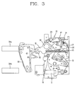
- FIG. 3 is a state view showing the general air circuit breaker is closed and the closing spring is elastically discharged, which can be implemented when the air circuit breaker is opened as shown in FIG. 2 and the closing spring is changed into the elastically discharged state from the elastically charged state.
- the on coupling 17 is moved rightwardly in the state shown in FIG. 2 in manual by using an on button (not shown) or in automatic by using the closing solenoid (not shown)
- the on lever 14 is rotated in the clockwise direction by pressing of the on coupling 17. Accordingly, the closing latch 13 being locked by the on lever 14 is released and then the closing spring 11 maintained in the elastically charged state by the closing latch 13 discharges elastic energy.
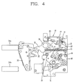
- FIG. 4 is a state view showing that the general air circuit breaker is closed and the closing spring is charged, which shows that the air circuit breaker is closed as shown in FIG. 3 and then the closing spring is charged. A process that the air circuit breaker is closed and the closing spring is charged is same as the aforementioned description, thus will be omitted.
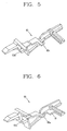
- FIG. 5 is a perspective view entirely showing an appearance of an on coupling of the air circuit breaker in accordance with the related art.
- the on coupling 60 of the air circuit breaker in the related art which is the same part designated as reference numeral 17 on Fig. 1-4 includes an on lever contacting part 60b serving as an operation part and disposed at the front surface (left side on the drawing) so as to rotate the on lever 14 by pressing the same, and a bias spring suspender 60a disposed at a central upper portion in a length direction.
- the bias spring suspender 60a for supterminaling (i.e. engaging) one end of a bias spring 62 (refer to Fig. 9 ) providing an elastic force for moving the on coupling 60 to the front surface of the air circuit breaker.
- the air circuit breaker is mechanically configured so that the closing operation cannot be allowed in a state that the contactors are contacted with each other and the closing spring is charged as shown in FIG. 4 .
- a user doesn't know this characteristic of the air circuit breaker may instruct the closing operation by pressing the closing button. In this case, since the closing operation is not performed, the user may misunderstand that the air circuit breaker is out of order.
- US 5,661,627 A discloses a power circuit breaker according to the preamble of claim 1 with an arrangement that controls its switching-on depending on operation parameters.
- a reporting switch can be actuated to signal electrically the readiness to switch on.
- US 4,301,342 A discloses a switchgear apparatus comprising a mechanical visualization means with three positions, e.g. a "ready to close" position.
- the present invention is directed to an improved circuit breaker having an apparatus for indicating a closing operable state which is capable of informing that the air circuit breaker is in the closing operable state when the air circuit breaker is located at a remote place or mounted in a power distributing cage.
- an apparatus for indicating a closing operable state for an air circuit breaker comprises a micro switch installed at a switching mechanism providing a driving force for switching contactors, provided with a lever extended into the switching mechanism so as to receive the driving force, generating and outputting an electric signal for indicating that the air circuit breaker is in a closing operable state, and provided with a signal transmitting terminal for transmitting the electric signal to a remote place; and an on coupling pressing the lever of the micro switch so that the micro switch generates and outputs the electric signal only when a closing spring for providing elastic energy for switching the contactors charges elastic energy and the air circuit breaker is opened.
- an air circuit breaker having an apparatus for indicating a closing operable state comprising a stationary contactor connected to a circuit, a movable contactor that can be moved to a closing position for conducting the circuit by coming into contact with the stationary contactor or an opening position for disconnecting the circuit by being separated from the stationary contactor, a closing spring providing a driving force for moving the movable contactor to the closing position when discharging charged elastic energy, a switching mechanism transmitting the discharging energy of the closing spring to the movable contactor, a closing latch that can be moved to a locking position for locking the switching mechanism so as to maintain the closing spring in the elastically charged state or a releasing position for releasing the switching mechanism so as to discharge the charged elastic energy, an on lever rotationally driven by coming into contact with the closing latch so as to move the closing latch to the releasing position, a closing button for manually instructing a closing operation, and an on coupling driven by coming into contact with the closing button so as to rotate the on lever.
- the apparatus for indicating the closing operable state comprises a micro switch installed on a moving path of the on coupling moving to a position where it comes into contact with the on lever and indicating that the air circuit breaker is in the closing operable state with a lever coming into contact with the on coupling moving to the position where it comes into contact with the on lever when the closing spring charges elastic energy and the movable contactor is opened, and a switch operation part installed at the on coupling so as to allow the lever of the micro switch to be pressed so that the micro switch generates and outputs an electric signal when the closing spring charges elastic energy and the movable contactor is opened.
- FIGS. 6 to 10 An apparatus for indicating a closing operable state for an air circuit breaker in accordance with the present invention will be described with reference to FIGS. 6 to 10 .
- the apparatus for indicating the closing operable state for the air circuit breaker includes a micro switch 72 and the on coupling 60.
- the micro switch 72 is installed on the switching mechanism 10 of the air circuit breaker 1 providing a driving force for switching contactors.
- the micro switch 72 is provided with a lever 71 extended into the switching mechanism 10.
- the micro switch 72 is provided with signal transmitting terminals 75a, 75b.
- a switch operation part 61 is installed to face the lever 71 of the micro switch 72 so as for the micro switch 72 to generate and output the electric signal and for the on coupling 60 to press the lever 71 of the micro switch 72.
- the apparatus for indicating the closing operable state for the air circuit breaker is formed by an electrically insulating material and further includes a switch case mounting the micro switch 72 therein.
- the switch case includes a case main body 73 having one opened surface, mounting the micro switch 72 therein and fixable to the switching mechanism 10, and a door 76 by which the opened surface of the case main body 73 can be opened or closed.
- the switch case is provided with a locking mechanism 73b1-73b3, 76a1-76a3, 76c, 73d at the door 76 and the case main body 73 corresponding to the door 76 so that the door 76 can maintain its closed state.
- the locking mechanism 73b1-73b3, 76a1-76a3, 76c, 73d is composed of locking protrusions 73b1-73b3, 76c and a locking groove 73d or locking openings 76a1-76a3 into which the locking protrusions 73b1-73b3, 76c are inserted.
- the locking protrusions may be disposed at the door 76 and the locking groove or the locking openings may be disposed at the case main body 73, and vice versa.
- the locking protrusions 73b1-73b3, 76c include the locking protrusions 73b1-73b3 disposed to correspond to the locking openings 76a1-76a3 formed at three positions, i.e., upper, middle and lower positions, adjacent to an opposite side of a hinge of the door 76, and the lower locking protrusion 76c disposed at an lower end of the door 76.
- the micro switch 72 is provided with two screw insertion holes in a diagonal direction at two of upper and lower positions. Each fixing screw is inserted into the two screw insertion holes so as to fix the micro switch 72 to the case main body 73.
- reference numerals 72a1 and 72a2 designate heads of upper and lower fixing screws.
- upper and lower fixing screw insertions holes 76b1, 76b2 allowing the fixing screws to be inserted thereinto are provided at the door 76.
- the door 76 and the case main body 73 are connected to each other by a chamfer 77 having a thickness thinner than other portion of the switch case and serving as a hinge portion for rotatably opening or closing the door 76.
- the case main body 73 includes a insertion fixing protrusion 74 downwardly extended from a lower surface of the case main body 73 and a screw fixing protrusion 73a horizontally extended from the lower side of the case main body 73, so as to fix the switch case to the switching mechanism (refer to a reference numeral 10 of FIGS. 9 and 10 ).
- a screw hole 73a1 is provided at a middle portion of the screw fixing protrusion 73a.
- the case main body 73 includes an opening wall for a lever 73e allowing the lever 71 of the micro switch 72 to be outwardly protruded even when the door 76 is closed, and an opening wall for introducing a signal wire 73c allowing the signal wire (not shown) connected to signal transmitting terminals 75a, 75b of the micro switch 72 to be introduced thereinto.
- FIG. 8 is a top view showing the switch case of FIG. 7 when the door 76 is opened.
- FIG. 8 it can be seen how much the locking mechanism and the screw fixing protrusion 73a are protruded and how they are relatively positioned on the horizontal direction.
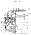
- FIGS. 9 and 10 a configuration and an operation of the air circuit breaker 1 having the apparatus for indicating the closing operable state in accordance with the present invention will be described.
- the air circuit breaker 1 includes the stationary contactor connected to the circuit and the movable contactor that can be moved to a closing position for conducting the circuit by coming into contact with the stationary contactor or an opening position for disconnecting the circuit by being separated from the stationary contactor.
- the stationary contactor and the movable contactor are generally disclosed for the air circuit breaker, thus additional drawings and description about the contactors will be omitted.
- the stationary contactor is fixedly installed on a rear common insulating wall 2 between insulating partition walls 1 a-1d adjacent to each other, and the movable contactor is movably installed between the insulating partition walls 1 a-1 d adjacent to each other.
- the air circuit breaker 1 includes the closing spring 11 providing the movable contactor with the driving force for moving the closing position when discharging the charged elastic energy, the switching mechanism 10 transmitting the discharged energy of the closing spring 11 to the movable contactor, the closing latch 13, the on lever (not shown, refer to the reference number 14 in FIG. 4 ), a closing button (not shown), and the on coupling 60.
- the closing latch 13 can be moved to a locking position for locking the switching mechanism 10 or a releasing position for releasing the switching mechanism so as to discharge the charged elastic energy of the closing spring.
- the on lever (not shown, refer to the reference numeral 14 in FIG. 4 ) may be rotatably driven to allow the closing latch 13 to be moved to the releasing position by coming into contact with the closing latch 13.
- the closing button (not shown) serves to manually instruct the closing operation.
- the on coupling 60 coming into contact with the closing button can be driven to rotate the on lever.
- the air circuit breaker in accordance with the present invention includes the micro switch 72 and the switch operation part 61 installed at the on coupling 60 as characteristic components.
- the micro switch 72 is installed on a moving path of the on coupling 60 moving to a position for coming into contact with the on lever (not shown, refer to the reference numeral 14 in FIG. 4 ).
- the micro switch 72 When the closing spring 11 charges the elastic energy and the movable contactor is opened, the micro switch 72 is provided with a lever 71 coming into contact with the on coupling 60 moving to the position for coming into contact with the on lever.
- the micro switch 72 generates and outputs an electric signal for indicating that the air circuit breaker is in the closing operable state.
- the on coupling 60 is provided with the switch operation part 61 pressing the lever 71 of the micro switch 72, the lever 71 allowing the micro switch 72 to generate and output the electric signal.
- the switch operation part 61 is installed at a position facing the lever 71 of the micro switch 72 and protruded by a pressed distance of the lever 71 of the micro switch 72 long enough to operate the micro switch 72. That is, the switch operation part 61 is protruded toward the lever 71 of the micro switch 72 from the on coupling 60 by a predetermined distance long enough to move the lever 71 of the micro switch 72 so as to generate the electric signal transmitting that the air circuit breaker is in the closing operable state resulting from that inner electric contactors of the micro switch 72 are opened or closed.
- the air circuit breaker in accordance with the present invention further includes the switch case installed on an top plate 80 of the switching mechanism 10 by being formed by an electric insulating material, mounting the micro switch 72 therein and provided with the door 76 that can be opened or closed.
- an unexplained reference numeral 81 indicates a lever insertion hole into which the lever 71 of the micro switch 72 disposed on the top plate 80 of the switching mechanism 10 can be inserted.
- a reference numeral 82 indicates a lower locking protrusion insertion hole into which the lower locking protrusion 74 disposed at the lower surface of the case main body 73 of the switch case is inserted so as to allowing the switch case to fix onto the top plate 80 of the switching mechanism 10.
- a reference numeral 83 indicates a screw insertion hole portion into which the fixing screw is inserted so as to fix the switch case by being communicated with the screw insertion hole 73a1 of the screw fixing protrusion 73a horizontally extended from the lower surface of the case main body 73.
- the on coupling (refer to the reference numeral 17 in FIG. 4 , and the reference numeral 60 in FIG. 10 ) is located at a position where it comes into contact with the on lever 14. Accordingly, the switch operation part 61 of the on coupling 60 presses the lever 71 of the micro switch 72, for operating the micro switch 72, thereby, separating or contacting the contactors (not shown) in the micro switch 72. Thus, the micro switch 72 generates a closing operable signal indicating that the air circuit breaker is in the closing operable state.
- the closing operable signal is transmitted to the remote place or the door (manipulating and displaying portion at the front surface) of the power distributing cage, which makes a lamp, a buzzer, etc. be driven, for example. Accordingly, it is capable of informing the user that the air circuit breaker is in the closing operable state.
Claims (10)
- Druckluftschalter mit einer Vorrichtung zum Anzeigen eines Betriebsschließstatus, umfassend einen stationären Schalter (34a), der mit einer Schaltung verbunden ist, einen beweglichen Schalter (33), der zu einer Schließposition zur Leitung der Schaltung durch Kontaktieren mit dem stationären Schalter oder zu einer Öffnungsposition zum Abtrennen der Schaltung durch Lösung vom stationären Schalter bewegt werden kann, eine Schließfeder (11), die eine treibende Kraft zum Bewegen des beweglichen Schalters zur Schließposition während einer Entladung einer geladenen elastischen Energie bereitstellt, einen Schaltmechanismus (10), der die entladende Energie der schließenden Feder an den beweglichen Schalter überträgt, eine Schließzunge (13), die zu einer Verriegelungsposition zum Verriegeln des Schaltmechanismus bewegt werden kann, um die Schließfeder im elastisch geladenen Zustand aufrecht zu erhalten, oder zu einer Auslösungsposition zum Auslösen des Schaltmechanismus bewegt werden kann, um die geladene elastische Energie zu entladen, einen Ein-Hebel (14), der durch Kontaktierung mit der Schließzunge drehend angetrieben ist, um die Schließzunge zur Auslösungsposition zu bewegen, einen Schließknopf zum manuellen Instruieren eines Schließvorgangs, und eine Ein-Kopplung, die durch Kontaktierung mit dem Schließknopf getrieben wird, um den Ein-Hebel zu rotieren,
wobei die Vorrichtung zum Anzeigen des Betriebsschließstatus einen Mikroschalter (72) umfasst, der mit einem Signalübertragungsanschluss (75a, 75b) zum Übertragen des elektrischen Signals an einen entfernten Ort versehen ist, und auf einem beweglichen Pfad der Ein-Kopplung (60) angeordnet ist, die sich zu einer Position bewegt, an welcher sie in Kontakt mit dem Ein-Hebel tritt, und anzeigt, dass der Druckluftschalter im Betriebsschließstatus ist, wobei ein Hebel (71) des Mikroschalters mit der Ein-Kopplung in Kontakt tritt, die sich zur Position bewegt, an der sie in Kontakt mit dem Ein-Hebel tritt, wenn die Schließfeder elastische Energie auflädt und der bewegliche Schalter geöffnet wird, dadurch gekennzeichnet, dass die Ein-Kopplung einen einzigen Körper und einen Schaltbetriebsteil (61) aufweist, der von einer vertikalen Fläche der Ein-Kopplung herausragt, wobei eine Kante des Schaltbetriebsteils dem Hebel des Mikroschalters gegenübersteht und dazu eingerichtet ist, diesen zu drücken, der Schaltbetriebsteil auf der Ein-Kopplung vorgesehen ist, um es dem Hebel des Mikroschalters zu ermöglichen, gedrückt zu werden, so dass der Mikroschalter ein elektrisches Signal erzeugt und ausgibt, wenn die Schließfeder elastische Energie auflädt und der bewegliche Schalter geöffnet wird. - Druckluftschalter nach Anspruch 1, bei welchem der Schalterbetriebsteil mit einem gedrückten Abstand vom Hebel des Mikroschalters herausragt, der lang genug ist, um den Mikroschalter zu betreiben.
- Druckluftschalter nach Anspruch 1, weiterhin umfassend ein Schaltergehäuse, das auf einer oberen Platte des Schaltmechanismus angeordnet ist, indem es durch ein elektrisch isolierendes Material gebildet wird, der Mikroschalter hineinmontiert wird und es mit einer Tür (76) versehen wird, die geöffnet oder geschlossen werden kann.
- Druckluftschalter nach Anspruch 1, bei welchem der Hebel (71) in den Schaltmechanismus erstreckt wird, um die treibende Kraft aufzunehmen.
- Druckluftschalter nach Anspruch 4, weiterhin umfassend ein Schaltgehäuse, das durch ein elektrisch isolierendes Material gebildet ist und den montierten Mikroschalter einschließt, wobei das Schaltgehäuse Folgendes umfasst:einen Gehäusehauptkörper (73) mit einer geöffneten Fläche, auf der der Mikroschalter montiert ist und die mit dem Schaltmechanismus befestigbar ist; undeine Tür (76), durch die die geöffnete Fläche des Gehäusehauptkörpers geöffnet oder geschlossen werden kann.
- Druckluftschalter nach Anspruch 5, bei welchem das Schaltgehäuse weiterhin einen Verriegelungsmechanismus (73) an der Tür umfasst und der Gehäusehauptkörper der Tür entspricht, um die Tür im geschlossenen Zustand zu halten.
- Druckluftschalter nach Anspruch 6, bei welchem der Verriegelungsmechanismus Verriegelungsvorsprünge und eine Verriegelungsrille (73d) oder Verriegelungsöffnungen, in die die Verriegelungsvorsprünge eingefügt werden, umfasst, wobei die Verriegelungsvorsprünge an der Tür und der Verriegelungsrille angeordnet sind oder die Verriegelungsöffnungen am Gehäusehauptkörper angeordnet sind, und umgekehrt.
- Druckluftschalter nach Anspruch 5, bei welchem die Tür und der Gehäusehauptkörper über eine Abschrägung (77) miteinander verbunden sind, die eine Dicke aufweist, die dünner als ein anderer Teil des Schaltgehäuses ist und als ein Scharnierabschnitt zum drehenden Öffnen oder Schließen der Tür dient.
- Druckluftschalter nach Anspruch 5, bei welchem der Gehäusehauptkörper Folgendes umfasst:einen Befestigungsvorsprung (74) zur Einfügung, der sich nach unten von einer unteren Fläche des Gehäusehauptkörpers erstreckt; undeinen Schraubenbefestigungsvorsprung (73a), der sich horizontal von der unteren Seite des Gehäusehauptkörpers erstreckt, um das Schaltgehäuse mit dem Schaltmechanismus zu befestigen.
- Druckluftschalter nach Anspruch 5, bei welchem der Gehäusehauptkörper Folgendes umfasst:eine Öffnungswand (73e), die es dem Hebel des Mikroschalters ermöglicht, nach außen herauszuragen, selbst wenn die Tür geschlossen ist; undeine Öffnungswand (73c) zum Einführen eines Signaldrahtes, die es dem Signaldraht, der mit dem Signalübertragungsanschluss des Mikroschalters verbunden ist, ermöglicht, darin aufgenommen zu werden.
Applications Claiming Priority (1)
| Application Number | Priority Date | Filing Date | Title |
|---|---|---|---|
| KR1020070070270A KR100890754B1 (ko) | 2007-07-12 | 2007-07-12 | 기중 차단기용 투입작동 가능 표시장치 및 이를 갖는 기중차단기 |
Publications (3)
| Publication Number | Publication Date |
|---|---|
| EP2015337A2 EP2015337A2 (de) | 2009-01-14 |
| EP2015337A3 EP2015337A3 (de) | 2011-01-12 |
| EP2015337B1 true EP2015337B1 (de) | 2016-05-04 |
Family
ID=39789625
Family Applications (1)
| Application Number | Title | Priority Date | Filing Date |
|---|---|---|---|
| EP08011914.2A Active EP2015337B1 (de) | 2007-07-12 | 2008-07-02 | Gerät zur Betriebsschließstatusanzeige für einen Druckluftschalter und Druckluftschalter damit |
Country Status (8)
| Country | Link |
|---|---|
| US (1) | US7985936B2 (de) |
| EP (1) | EP2015337B1 (de) |
| JP (1) | JP4567772B2 (de) |
| KR (1) | KR100890754B1 (de) |
| CN (1) | CN101388304B (de) |
| ES (1) | ES2585128T3 (de) |
| MY (1) | MY157910A (de) |
| RU (1) | RU2372683C1 (de) |
Cited By (1)
| Publication number | Priority date | Publication date | Assignee | Title |
|---|---|---|---|---|
| CN113611581A (zh) * | 2021-10-11 | 2021-11-05 | 江苏南瓯物联网科技有限公司 | 一种智能空气断路器 |
Families Citing this family (18)
| Publication number | Priority date | Publication date | Assignee | Title |
|---|---|---|---|---|
| JP4062574B2 (ja) * | 1999-09-07 | 2008-03-19 | Thk株式会社 | 転動体連結体の製造方法 |
| KR100876408B1 (ko) * | 2007-07-12 | 2008-12-31 | 엘에스산전 주식회사 | 기계적 트립 표시 기구를 갖는 기중 차단기 |
| KR100876412B1 (ko) * | 2007-07-12 | 2008-12-31 | 엘에스산전 주식회사 | 차단기의 지연시간 출력장치 |
| KR100882399B1 (ko) * | 2007-08-20 | 2009-02-05 | 엘에스산전 주식회사 | 자동 풀림 링크 기구를 구비한 회로 차단기 및 이에사용되는 자동풀림 링크 기구 |
| US7906740B2 (en) | 2008-04-15 | 2011-03-15 | General Electric Company | Readiness for closing indicator for circuit breakers |
| US9080776B2 (en) * | 2008-08-26 | 2015-07-14 | General Electric Company | Fan apparency arrangement for an appliance |
| KR101016212B1 (ko) * | 2008-10-23 | 2011-02-25 | 거성엔지니어링 주식회사 | 마이크로 스위치 |
| KR101082175B1 (ko) * | 2010-01-27 | 2011-11-09 | 엘에스산전 주식회사 | 트립 알람수단을 가진 회로차단기 |
| US8217291B2 (en) * | 2010-03-04 | 2012-07-10 | Eaton Corporation | Electrical switching apparatus and status indicating assembly therefor |
| CN102412101A (zh) * | 2011-07-27 | 2012-04-11 | 杭州之江开关股份有限公司 | 一种断路器三位置电信号输出装置 |
| RU2619764C1 (ru) * | 2013-12-05 | 2017-05-18 | Деликси Электрик Лтд | Крепежная конструкция контактной пластины |
| CN104377057B (zh) * | 2014-11-13 | 2017-05-10 | 无锡江南奕帆电力传动科技股份有限公司 | 一种便于观察的断路器位置指示装置 |
| KR101704433B1 (ko) * | 2015-05-13 | 2017-02-09 | 현대중공업 주식회사 | 회로차단기 |
| KR101698814B1 (ko) * | 2015-05-13 | 2017-01-24 | 현대중공업 주식회사 | 차단기 |
| KR101699699B1 (ko) * | 2015-05-14 | 2017-01-31 | 현대중공업 주식회사 | 회로 차단기용 스위치 잠금장치 |
| KR102513352B1 (ko) * | 2016-02-25 | 2023-03-23 | 엘에스일렉트릭(주) | 상태표시기능을 갖는 상입형 전자개폐기 |
| ES2946269T3 (es) * | 2018-04-23 | 2023-07-14 | Abb Spa | Disyuntor |
| FR3087273B1 (fr) * | 2018-10-15 | 2020-11-06 | Schneider Electric Ind Sas | Dispositif de mesure et appareil de commutation electrique |
Citations (4)
| Publication number | Priority date | Publication date | Assignee | Title |
|---|---|---|---|---|
| US4166989A (en) * | 1978-04-19 | 1979-09-04 | General Electric Company | Circuit breaker remote close and charged signalling apparatus |
| US4301342A (en) * | 1980-06-23 | 1981-11-17 | General Electric Company | Circuit breaker condition indicator apparatus |
| US5661627A (en) * | 1993-09-30 | 1997-08-26 | Siemens Aktiengesellschaft | Arrangement for controlling the switching of a power circuit breaker |
| US6144002A (en) * | 1998-10-30 | 2000-11-07 | Schneider Electric Industries Sa | Switchgear apparatus comprising a mechanical visualization means with three positions |
Family Cites Families (29)
| Publication number | Priority date | Publication date | Assignee | Title |
|---|---|---|---|---|
| JPS55108118A (en) | 1979-02-13 | 1980-08-19 | Tokyo Shibaura Electric Co | Motorrdriven spring operating device for circuit breaker |
| JPS58131636A (ja) | 1982-01-29 | 1983-08-05 | 松下電工株式会社 | リモ−トコントロ−ル式回路しや断器 |
| JPS58115046U (ja) * | 1982-01-29 | 1983-08-05 | 三菱電機株式会社 | 気中しや断器 |
| US4760226A (en) * | 1987-04-08 | 1988-07-26 | Carlingswitch, Inc. | Split case circuit breaker with multi-purpose well |
| US5041805A (en) | 1988-10-06 | 1991-08-20 | Mitsubishi Denki Kabushiki Kaisha | Remote-controlled circuit breaker |
| US5140115A (en) * | 1991-02-25 | 1992-08-18 | General Electric Company | Circuit breaker contacts condition indicator |
| US5278373A (en) | 1991-10-18 | 1994-01-11 | Square D Company | Current limiting circuit breaker |
| JP2986266B2 (ja) | 1991-11-05 | 1999-12-06 | 株式会社東芝 | ガス遮断器用再閉路準備回路 |
| FR2699324A1 (fr) | 1992-12-11 | 1994-06-17 | Gen Electric | Commutateur auxiliaire compact pour disjoncteur à boîtier moulé. |
| JPH07130251A (ja) | 1993-09-29 | 1995-05-19 | Meidensha Corp | 開閉器の操作装置 |
| US5485134A (en) * | 1994-05-31 | 1996-01-16 | General Electric Company | Auxiliary switch accessory module unit for high ampere-rated circuit breaker |
| JPH07335061A (ja) | 1994-06-06 | 1995-12-22 | Toko Denki Kk | 自動開閉器の動作状態検出装置 |
| JPH10199377A (ja) | 1997-01-09 | 1998-07-31 | Nissin Electric Co Ltd | 遮断器操作装置 |
| US5986225A (en) * | 1997-06-19 | 1999-11-16 | General Electric Company | Circuit breaker bell alarm accessory with lock-out |
| US6242703B1 (en) * | 1998-01-14 | 2001-06-05 | General Electric Company | Bell alarm with automatic reset for small frame air circuit breaker |
| US5936535A (en) * | 1998-05-29 | 1999-08-10 | General Electric Company | Circuit breaker bell alarm accessory |
| US6166343A (en) * | 1999-03-29 | 2000-12-26 | Siemens Energy & Automation, Inc. | Unidirectional clutch assembly for a stored energy circuit breaker operator assembly |
| JP2001143578A (ja) | 1999-11-12 | 2001-05-25 | Toshiba Corp | 遮断器の操作機構 |
| DE19957391C1 (de) * | 1999-11-24 | 2001-03-29 | Siemens Ag | Einrichtung zur Steuerung der Einschaltung eines Leistungsschalters |
| KR200266586Y1 (ko) * | 2001-11-17 | 2002-03-02 | 엘지산전 주식회사 | 진공차단기의 투입스프링 상태 표시기 구조 |
| US6864447B1 (en) * | 2003-08-28 | 2005-03-08 | Eaton Corporation | Circuit breaker empolying illuminating indicators for open and closed positions |
| FR2859816B1 (fr) | 2003-09-11 | 2006-04-07 | Legrand Sa | Dispositif de coupure de courant electrique a discrimination complete d'etats |
| RU2257636C1 (ru) | 2004-04-15 | 2005-07-27 | Джус Илья Николаевич | Устройство для контроля состояния контакта выключателя (варианты) |
| US20080122563A1 (en) | 2006-08-28 | 2008-05-29 | Ls Industrial Systems Co., Ltd. | Instantaneous trip mechanism for mould cased circuit breaker |
| KR100771918B1 (ko) | 2006-10-17 | 2007-11-01 | 엘에스산전 주식회사 | 기중차단기의 개폐기구 |
| KR100817118B1 (ko) | 2006-10-17 | 2008-03-27 | 엘에스산전 주식회사 | 기중차단기의 가동접촉자 |
| KR100771922B1 (ko) | 2006-10-17 | 2007-11-01 | 엘에스산전 주식회사 | 기중 차단기 |
| KR100789448B1 (ko) | 2006-12-29 | 2007-12-28 | 엘에스산전 주식회사 | 배선용 차단기용 단자 모듈 조립체 및 상기 단자 모듈조립체를 장착한 배선용 차단기 |
| KR100876408B1 (ko) | 2007-07-12 | 2008-12-31 | 엘에스산전 주식회사 | 기계적 트립 표시 기구를 갖는 기중 차단기 |
-
2007
- 2007-07-12 KR KR1020070070270A patent/KR100890754B1/ko active IP Right Grant
-
2008
- 2008-06-30 US US12/164,691 patent/US7985936B2/en active Active
- 2008-07-02 ES ES08011914.2T patent/ES2585128T3/es active Active
- 2008-07-02 EP EP08011914.2A patent/EP2015337B1/de active Active
- 2008-07-08 MY MYPI20082525A patent/MY157910A/en unknown
- 2008-07-10 JP JP2008180091A patent/JP4567772B2/ja active Active
- 2008-07-11 CN CN2008101446527A patent/CN101388304B/zh active Active
- 2008-07-11 RU RU2008128391/09A patent/RU2372683C1/ru active
Patent Citations (4)
| Publication number | Priority date | Publication date | Assignee | Title |
|---|---|---|---|---|
| US4166989A (en) * | 1978-04-19 | 1979-09-04 | General Electric Company | Circuit breaker remote close and charged signalling apparatus |
| US4301342A (en) * | 1980-06-23 | 1981-11-17 | General Electric Company | Circuit breaker condition indicator apparatus |
| US5661627A (en) * | 1993-09-30 | 1997-08-26 | Siemens Aktiengesellschaft | Arrangement for controlling the switching of a power circuit breaker |
| US6144002A (en) * | 1998-10-30 | 2000-11-07 | Schneider Electric Industries Sa | Switchgear apparatus comprising a mechanical visualization means with three positions |
Cited By (1)
| Publication number | Priority date | Publication date | Assignee | Title |
|---|---|---|---|---|
| CN113611581A (zh) * | 2021-10-11 | 2021-11-05 | 江苏南瓯物联网科技有限公司 | 一种智能空气断路器 |
Also Published As
| Publication number | Publication date |
|---|---|
| US7985936B2 (en) | 2011-07-26 |
| KR100890754B1 (ko) | 2009-03-26 |
| MY157910A (en) | 2016-08-15 |
| EP2015337A3 (de) | 2011-01-12 |
| RU2372683C1 (ru) | 2009-11-10 |
| ES2585128T3 (es) | 2016-10-04 |
| JP4567772B2 (ja) | 2010-10-20 |
| CN101388304B (zh) | 2012-05-23 |
| EP2015337A2 (de) | 2009-01-14 |
| US20090014300A1 (en) | 2009-01-15 |
| JP2009021246A (ja) | 2009-01-29 |
| KR20090006681A (ko) | 2009-01-15 |
| CN101388304A (zh) | 2009-03-18 |
Similar Documents
| Publication | Publication Date | Title |
|---|---|---|
| EP2015337B1 (de) | Gerät zur Betriebsschließstatusanzeige für einen Druckluftschalter und Druckluftschalter damit | |
| US7655877B2 (en) | Air circuit breaker with mechanical trip indicating mechanism | |
| US8368489B2 (en) | Circuit breaker having trip cause indicating mechanism | |
| KR100850422B1 (ko) | 기중차단기의 투입스프링 차징장치 | |
| US7701313B2 (en) | Case for circuit breaker with monolithic door | |
| KR100898469B1 (ko) | 누전 차단기 | |
| EP2610882B1 (de) | Schutzschalter mit mechanischem Freiauslösemechanismus | |
| US6552286B2 (en) | Handle operating mechanism of circuit breaker | |
| KR100445886B1 (ko) | 회로차단기 | |
| EP1148530A1 (de) | Steckbarer leistungsschalter | |
| CN101484960A (zh) | 接地断路器 | |
| KR100857012B1 (ko) | 기중차단기용 인터록장치 | |
| EP2015334B1 (de) | Luftschalter mit einfach anbringbarer Struktur für ein Überstromrelais | |
| CN217239371U (zh) | 分合闸机构和微型断路器 | |
| JP3418670B2 (ja) | 回路遮断器 | |
| JP3867540B2 (ja) | 開閉装置 | |
| JPH06338248A (ja) | 回路遮断器 | |
| JPH06338250A (ja) | 回路遮断器 | |
| CN112424900A (zh) | 断路器 | |
| JP2000200535A (ja) | 回路遮断器 | |
| JPH06338249A (ja) | 回路遮断器 | |
| JP2001297681A (ja) | 回路しゃ断器 | |
| JPH06338247A (ja) | 回路遮断器 | |
| JP2015032540A (ja) | 回路遮断器 |
Legal Events
| Date | Code | Title | Description |
|---|---|---|---|
| PUAI | Public reference made under article 153(3) epc to a published international application that has entered the european phase |
Free format text: ORIGINAL CODE: 0009012 |
|
| 17P | Request for examination filed |
Effective date: 20080702 |
|
| AK | Designated contracting states |
Kind code of ref document: A2 Designated state(s): AT BE BG CH CY CZ DE DK EE ES FI FR GB GR HR HU IE IS IT LI LT LU LV MC MT NL NO PL PT RO SE SI SK TR |
|
| AX | Request for extension of the european patent |
Extension state: AL BA MK RS |
|
| PUAL | Search report despatched |
Free format text: ORIGINAL CODE: 0009013 |
|
| AK | Designated contracting states |
Kind code of ref document: A3 Designated state(s): AT BE BG CH CY CZ DE DK EE ES FI FR GB GR HR HU IE IS IT LI LT LU LV MC MT NL NO PL PT RO SE SI SK TR |
|
| AX | Request for extension of the european patent |
Extension state: AL BA MK RS |
|
| AKX | Designation fees paid |
Designated state(s): DE ES FR GB IT |
|
| 17Q | First examination report despatched |
Effective date: 20140226 |
|
| GRAP | Despatch of communication of intention to grant a patent |
Free format text: ORIGINAL CODE: EPIDOSNIGR1 |
|
| INTG | Intention to grant announced |
Effective date: 20151112 |
|
| GRAS | Grant fee paid |
Free format text: ORIGINAL CODE: EPIDOSNIGR3 |
|
| GRAA | (expected) grant |
Free format text: ORIGINAL CODE: 0009210 |
|
| AK | Designated contracting states |
Kind code of ref document: B1 Designated state(s): DE ES FR GB IT |
|
| REG | Reference to a national code |
Ref country code: GB Ref legal event code: FG4D |
|
| REG | Reference to a national code |
Ref country code: DE Ref legal event code: R096 Ref document number: 602008043941 Country of ref document: DE |
|
| REG | Reference to a national code |
Ref country code: FR Ref legal event code: PLFP Year of fee payment: 9 |
|
| REG | Reference to a national code |
Ref country code: ES Ref legal event code: FG2A Ref document number: 2585128 Country of ref document: ES Kind code of ref document: T3 Effective date: 20161004 |
|
| REG | Reference to a national code |
Ref country code: DE Ref legal event code: R097 Ref document number: 602008043941 Country of ref document: DE |
|
| PLBE | No opposition filed within time limit |
Free format text: ORIGINAL CODE: 0009261 |
|
| STAA | Information on the status of an ep patent application or granted ep patent |
Free format text: STATUS: NO OPPOSITION FILED WITHIN TIME LIMIT |
|
| 26N | No opposition filed |
Effective date: 20170207 |
|
| REG | Reference to a national code |
Ref country code: FR Ref legal event code: PLFP Year of fee payment: 10 |
|
| REG | Reference to a national code |
Ref country code: FR Ref legal event code: PLFP Year of fee payment: 11 |
|
| PGFP | Annual fee paid to national office [announced via postgrant information from national office to epo] |
Ref country code: IT Payment date: 20230608 Year of fee payment: 16 Ref country code: FR Payment date: 20230609 Year of fee payment: 16 |
|
| P01 | Opt-out of the competence of the unified patent court (upc) registered |
Effective date: 20230625 |
|
| PGFP | Annual fee paid to national office [announced via postgrant information from national office to epo] |
Ref country code: GB Payment date: 20230607 Year of fee payment: 16 Ref country code: ES Payment date: 20230814 Year of fee payment: 16 |
|
| PGFP | Annual fee paid to national office [announced via postgrant information from national office to epo] |
Ref country code: DE Payment date: 20230607 Year of fee payment: 16 |