EP2015005A2 - Air conditioner and method for controlling the same - Google Patents
Air conditioner and method for controlling the same Download PDFInfo
- Publication number
- EP2015005A2 EP2015005A2 EP08012385A EP08012385A EP2015005A2 EP 2015005 A2 EP2015005 A2 EP 2015005A2 EP 08012385 A EP08012385 A EP 08012385A EP 08012385 A EP08012385 A EP 08012385A EP 2015005 A2 EP2015005 A2 EP 2015005A2
- Authority
- EP
- European Patent Office
- Prior art keywords
- refrigerant
- indoor
- unit
- indoor unit
- valve
- Prior art date
- Legal status (The legal status is an assumption and is not a legal conclusion. Google has not performed a legal analysis and makes no representation as to the accuracy of the status listed.)
- Granted
Links
Images


Classifications
-
- F—MECHANICAL ENGINEERING; LIGHTING; HEATING; WEAPONS; BLASTING
- F25—REFRIGERATION OR COOLING; COMBINED HEATING AND REFRIGERATION SYSTEMS; HEAT PUMP SYSTEMS; MANUFACTURE OR STORAGE OF ICE; LIQUEFACTION SOLIDIFICATION OF GASES
- F25B—REFRIGERATION MACHINES, PLANTS OR SYSTEMS; COMBINED HEATING AND REFRIGERATION SYSTEMS; HEAT PUMP SYSTEMS
- F25B13/00—Compression machines, plants or systems, with reversible cycle
-
- F—MECHANICAL ENGINEERING; LIGHTING; HEATING; WEAPONS; BLASTING
- F25—REFRIGERATION OR COOLING; COMBINED HEATING AND REFRIGERATION SYSTEMS; HEAT PUMP SYSTEMS; MANUFACTURE OR STORAGE OF ICE; LIQUEFACTION SOLIDIFICATION OF GASES
- F25B—REFRIGERATION MACHINES, PLANTS OR SYSTEMS; COMBINED HEATING AND REFRIGERATION SYSTEMS; HEAT PUMP SYSTEMS
- F25B45/00—Arrangements for charging or discharging refrigerant
-
- F—MECHANICAL ENGINEERING; LIGHTING; HEATING; WEAPONS; BLASTING
- F24—HEATING; RANGES; VENTILATING
- F24F—AIR-CONDITIONING; AIR-HUMIDIFICATION; VENTILATION; USE OF AIR CURRENTS FOR SCREENING
- F24F11/00—Control or safety arrangements
- F24F11/50—Control or safety arrangements characterised by user interfaces or communication
- F24F11/54—Control or safety arrangements characterised by user interfaces or communication using one central controller connected to several sub-controllers
-
- F—MECHANICAL ENGINEERING; LIGHTING; HEATING; WEAPONS; BLASTING
- F25—REFRIGERATION OR COOLING; COMBINED HEATING AND REFRIGERATION SYSTEMS; HEAT PUMP SYSTEMS; MANUFACTURE OR STORAGE OF ICE; LIQUEFACTION SOLIDIFICATION OF GASES
- F25B—REFRIGERATION MACHINES, PLANTS OR SYSTEMS; COMBINED HEATING AND REFRIGERATION SYSTEMS; HEAT PUMP SYSTEMS
- F25B2313/00—Compression machines, plants or systems with reversible cycle not otherwise provided for
- F25B2313/023—Compression machines, plants or systems with reversible cycle not otherwise provided for using multiple indoor units
- F25B2313/0233—Compression machines, plants or systems with reversible cycle not otherwise provided for using multiple indoor units in parallel arrangements
-
- F—MECHANICAL ENGINEERING; LIGHTING; HEATING; WEAPONS; BLASTING
- F25—REFRIGERATION OR COOLING; COMBINED HEATING AND REFRIGERATION SYSTEMS; HEAT PUMP SYSTEMS; MANUFACTURE OR STORAGE OF ICE; LIQUEFACTION SOLIDIFICATION OF GASES
- F25B—REFRIGERATION MACHINES, PLANTS OR SYSTEMS; COMBINED HEATING AND REFRIGERATION SYSTEMS; HEAT PUMP SYSTEMS
- F25B2313/00—Compression machines, plants or systems with reversible cycle not otherwise provided for
- F25B2313/027—Compression machines, plants or systems with reversible cycle not otherwise provided for characterised by the reversing means
- F25B2313/02741—Compression machines, plants or systems with reversible cycle not otherwise provided for characterised by the reversing means using one four-way valve
-
- F—MECHANICAL ENGINEERING; LIGHTING; HEATING; WEAPONS; BLASTING
- F25—REFRIGERATION OR COOLING; COMBINED HEATING AND REFRIGERATION SYSTEMS; HEAT PUMP SYSTEMS; MANUFACTURE OR STORAGE OF ICE; LIQUEFACTION SOLIDIFICATION OF GASES
- F25B—REFRIGERATION MACHINES, PLANTS OR SYSTEMS; COMBINED HEATING AND REFRIGERATION SYSTEMS; HEAT PUMP SYSTEMS
- F25B2400/00—Component parts or details not otherwise provided for in this subclass
- F25B2400/19—Pumping down refrigerant from one part of the cycle to another part of the cycle, e.g. when the cycle is changed from cooling to heating, or before a defrost cycle is started
-
- F—MECHANICAL ENGINEERING; LIGHTING; HEATING; WEAPONS; BLASTING
- F25—REFRIGERATION OR COOLING; COMBINED HEATING AND REFRIGERATION SYSTEMS; HEAT PUMP SYSTEMS; MANUFACTURE OR STORAGE OF ICE; LIQUEFACTION SOLIDIFICATION OF GASES
- F25B—REFRIGERATION MACHINES, PLANTS OR SYSTEMS; COMBINED HEATING AND REFRIGERATION SYSTEMS; HEAT PUMP SYSTEMS
- F25B2600/00—Control issues
- F25B2600/25—Control of valves
- F25B2600/2513—Expansion valves
-
- F—MECHANICAL ENGINEERING; LIGHTING; HEATING; WEAPONS; BLASTING
- F25—REFRIGERATION OR COOLING; COMBINED HEATING AND REFRIGERATION SYSTEMS; HEAT PUMP SYSTEMS; MANUFACTURE OR STORAGE OF ICE; LIQUEFACTION SOLIDIFICATION OF GASES
- F25B—REFRIGERATION MACHINES, PLANTS OR SYSTEMS; COMBINED HEATING AND REFRIGERATION SYSTEMS; HEAT PUMP SYSTEMS
- F25B2600/00—Control issues
- F25B2600/25—Control of valves
- F25B2600/2519—On-off valves
Definitions
- the present invention relates to a multi-type air conditioner having plural indoor units combined with a single outdoor unit, and to a method for controlling such an air conditioner.
- Japanese Patent No. 2925694 discloses a multi-type air conditioner having plural indoor units connected to a single outdoor unit, in which one of the indoor units has a decompression valve and heat exchanger incorporated therein, and the other indoor unit has only a heat exchanger incorporated therein with a decompression valve provided in a refrigerant pipe connected to the other indoor unit.
- the other indoor unit has no decompression valve, but instead the decompression valve connected to the refrigerant pipe adjusts the amount of refrigerant. This allows coexistence of different types of indoor units such as package air conditioners and room air conditioners.
- the cycle balance is lost, resulting in lack of refrigerant in the cooling-heating cycle.
- the lack of refrigerant in the cooling cycle or heating cycle has negative effects, such as degradation of insulation due to insufficient cooling in a compressor motor, degradation of freezer oil and refrigerant due to increase of discharge gas temperature, and degradation of air conditioning performance due to reduction of refrigerant circulation amount.
- the lack of refrigerant in the cooling-heating cycle is solved by adding an appropriate amount of refrigerant.
- the present invention aims at providing an air conditioner designed to increase flexibility in installation of indoor units, by allowing connection of a predetermined number or more of indoor units to a single outdoor unit, or connection of indoor units whose total capacity exceeds the capacity of an outdoor unit, and providing a method for controlling such an air conditioner.
- the present invention is an air conditioner having an outdoor unit and plural indoor units connected by refrigerant pipes.
- an expansion valve is provided in one of plural refrigerant pipes connecting an arbitrary one of the indoor units with the outdoor unit, and an on-off valve is provided in another refrigerant pipe.
- the present invention is an air conditioner having an outdoor unit and plural indoor units connected by refrigerant pipes.
- the plural indoor units include a first indoor unit having an expansion valve and heat exchanger incorporated therein, and a second indoor unit having a heat exchanger but no expansion valve incorporated therein.
- an expansion valve is provided in one of plural refrigerant pipes connecting the second indoor unit with the outdoor unit, and an on-off valve is provided in another refrigerant pipe.
- the present invention is an air conditioner having an outdoor unit and plural indoor units connected by refrigerant pipes.
- the plural indoor units include a first indoor unit having an expansion valve and a heat exchanger incorporated therein, and a second indoor unit having a heat exchanger but no expansion valve incorporated therein.
- an on-off valve is connected to one of plural refrigerant pipes connecting the outdoor unit with the first indoor unit, which is other than the refrigerant pipe in which the expansion valve of the first indoor unit is provided.
- the present invention is a method for controlling an air conditioner having an outdoor unit and plural indoor units connected by refrigerant pipes.
- an expansion valve is provided in one of plural refrigerant pipes connecting an arbitrary one of the indoor units with the outdoor unit, and an on-off valve is provided in another refrigerant pipe.
- the method includes the steps of: closing, when stopping the arbitrary indoor unit, the valve provided in one of the plural refrigerant pipes, which is assigned to the outward flow, while opening the valve provided in the other refrigerant pipe; operating the arbitrary indoor unit for a predetermined period of time in such a state; and collecting the refrigerant from the arbitrary indoor unit into the outdoor unit via the open valve.
- the open valve provided in the other refrigerant pipe is closed after the operation for collecting the refrigerant from the indoor unit into the outdoor unit is performed for a predetermined period of time.
- the present invention is a method for controlling an air conditioner having an outdoor unit and plural indoor units connected by refrigerant pipes.
- the plurality indoor units include a first indoor unit hiving an expansion valve and a heart exchanger incorporated therein, and a second indoor unit having a heart exchanger but not expansion valve incorporated therein.
- an expansion valve is provided in one of plural refrigerant pipes connecting the second indoor unit with the outdoor unit, and an on-off valve is provided in another refrigerant pipe.
- the method includes the steps of: opening the valve provided in one of the plural refrigerant pipes connected to the second unit, which is assigned to the outward flow, while closing the valve provided in the other refrigerant pipe; operating the second indoor unit for a predetermined time in such a state; and collecting the refrigerant from the second indoor unit into the outdoor unit via the open valve.
- the valve provided in the other refrigerant pipe is closed after the refrigerant in the second indoor unit is collected in the outdoor unit.
- the present invention is a method for controlling an air conditioner having an outdoor unit and plural indoor units connected by refrigerant pipes.
- the plurality indoor units include a first indoor unit hiving an expansion valve and a heart exchanger incorporated therein, and a second indoor unit having a heart exchanger but not expansion valve incorporated therein.
- an on-off valve is connected to one of plural refrigerant pipes connecting the first indoor unit with the outdoor unit, which is other than the refrigerant pipe in which the expansion valve of the first indoor unit is provided.
- the method includes the steps of: closing the expansion valve of the first indoor unit while opening the on-off valve; operating the first indoor unit for a predetermined period of time in such a state; and collecting the refrigerant from the first indoor unit into the outdoor unit via the open on-off valve.
- the on-off valve is closed after the refrigerant in the first indoor unit is collected in the outdoor unit.
- an air conditioner designed to increase flexibility in installation of indoor units, by allowing connection of a predetermined number or more of indoor units to a single outdoor unit, or connection of indoor units whose total capacity exceeds the capacity of an outdoor unit, without suffering from a lack of refrigerant in the cooling-heating cycle.
- Fig. 1 is a configuration diagram of a cooling-heating cycle of a multi-air conditioner (a multi-type air conditioner) according to an embodiment of the present invention.
- the multi-air conditioner includes an outdoor unit A, plural indoor units a (a1, a2, and an) and b (b1, b2, and bn), and refrigerant pipes D1 D2 for connecting each of the units.
- the refrigerant pipes D1 D2 are branched and connected with a gas-side branch pipe 8 and a liquid-side branch pipe 9, respectively, to distribute and supply refrigerant to the indoor units a and b.
- the refrigerant pipe D1 is connected to a gas side stop valve 1 of the outdoor unit A, and the refrigerant pipe D2 is connected to a liquid side stop valve 2 thereof. In this way, a cooling-heating cycle system is formed.
- the indoor unit a is an indoor unit having a decompression device (indoor expansion valve 5) incorporated therein, and including an indoor fan 3 and an indoor heat exchanger 4.
- the indoor unit b is an indoor unit having no decompression device (indoor expansion valve 5) incorporated therein, and including the indoor fan 3 and the indoor heat exchanger 4.
- the indoor unit b is connected with an external decompression device C at the middle of the refrigerant pipes D2, D1 which are respectively connected to the liquid side branch pipe 9 and the gas side branch pipe 8.
- the external decompression device C has an expansion valve 6 externally connected to the refrigerant pipe D2, and an electromagnetic valve (on-off valve) 7 externally connected to the refrigerant pipe D1.
- the indoor unit a is referred to as a first indoor unit, and the indoor unit b as a second indoor unit.
- reference numeral 10 denotes a compressor
- 11 denotes a four-way valve
- 12 denotes an outdoor fan
- 13 denotes an outdoor heat exchanger
- 14 denotes an outdoor expansion valve
- 15 denotes a refrigerant tank
- 16 denotes an accumulator.
- the arrows indicate the directions of the refrigerant flowing through the refrigerant pipes. More specifically, the solid arrows indicate the flow in cooling operation, and the dotted arrows in the opposite direction indicate the flow in heating operation.
- the refrigerant flow direction is determined by switching of the four-way valve 11 in the outdoor unit A.
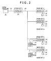
- Fig. 2 is a control block diagram according to an embodiment of the present invention.
- Reference numeral 17 denotes a remote control for providing operation instructions (such as operation, stop, operation mode, air volume/direction setting, and temperature setting) to the indoor units a, b.
- Reference numeral 18 denotes a remote control line.
- Reference numeral 20 denotes a central control unit for controlling the entire operation of the multi-air conditioner.
- Reference numeral 23 denotes a controller of the outdoor unit A.
- Reference numeral 24 denotes a controller of the indoor unit a.
- Reference numeral 25 denotes a controller of the indoor unit b.
- Reference numeral 21 denotes a central control transmission line for connecting the central control unit 20 and the controller 23.
- Reference numeral 19 denotes an indoor-outdoor transmission line for connecting the outdoor unit A and the indoor units a, b.
- Reference numeral 22 denotes an external decompression device transmission line for connecting the controller 25 and the external decompression device C.
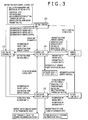
- Fig. 3 is a control system diagram according to an embodiment of the present invention.
- the remote control 17 first issues an operation instruction to the indoor unit a. Then, the controller 24 transmits the information about the state of the indoor unit a as well as the instruction of the remote control 17, to the outdoor unit A. Based on this transmission, the controller 23 of the outdoor unit A transmits the information of the outdoor unit A, the information of the indoor unit a, and the information (instruction) of the remote control 17, to the central control unit 20.
- the central control unit 20 Upon receiving such information, the central control unit 20 transmits an instruction (such as operation, stop, operation mode, air volume/direction setting, temperature setting, or remote control permission/prohibition), to the controller 23 in order to collectively manage the indoor units based on a control program stored in advance.
- the controller 23 transmits the instruction from the indoor unit A to the controller 24, based on the instruction of the central control unit 20.
- the controller 24 transmits the information of the indoor unit a as well as the information of the outdoor unit A, to the remote control 17.
- the controller 24 transmits an instruction for controlling the opening degree of the expansion valve, to the expansion valve 5 of the indoor unit a.
- the controller 25 transmits the information about the state of the indoor unit b as well as the instruction of the remote control 17, to the outdoor unit A in a similar way as described above. Based on this transmission, the controller 23 transmits the information of the outdoor unit A, the information of the indoor unit b, and the information (instruction) of the remote control 17, to the central control unit 20.
- the central control unit 20 Upon receiving such information, the central control unit 20 transmits an instruction (such as operation, stop, operation mode, air volume/direction setting, temperature setting, or remote control permission/prohibition) to the controller 23 in order to collectively manage the indoor units, based on a control program stored in advance.
- the controller 23 transmits the instruction from the indoor unit A to the controller 25 of the indoor unit b, based on the instruction of the central control unit 20.
- the controller 25 transmits the information of the indoor unit b as well as the information of the outdoor unit A, to the remote control 17.
- the controller 25 transmits an instruction for controlling the opening degree of the expansion valve, to the expansion valve 6 of the external decompression device C.
- controller 25 transmits an instruction for controlling on/off of the electromagnetic valve, to the electromagnetic valve 7 of the external decompression device C.
- the remote control information is exchanged between the remote controls 17, and the indoor unit information is exchanged between the indoor units 24 and 25.
- air conditioning operation of the control system is started by an operation instruction from the remote control 17 or from the central control unit 20.
- the air conditioning operation is continued with the entire system monitored by the central control unit 20.
- the remote control 1 or the central control unit 20 first issues an operation instruction, and the operation is finally started in step 101 based on the instruction of the central control unit 20. Next, it is determined whether there is a (stopped) indoor unit to which the operation instruction is not issued from the central control unit 20 in step 102. This determination is made by the central control unit 20 by collecting information of the indoor units a, b from the controllers 24, 25.
- step 120 all the indoor units are stopped from starting operation, and a warning is issued.
- step 103 determines whether the total capacity of the indoor units to be operated exceeds the capacity of the outdoor unit A.
- step 103 When the determination result is NO in step 103, the total capacity does not exceed the capacity of the outdoor unit A, so that it is possible to operate the indoor units to be operated. Thus, normal operation is started in step 121.
- step 103 When YES in step 103, the total capacity of the indoor units to be operated will exceed the capacity of the outdoor unit A, resulting in lack of refrigerant in the cooling-heating cycle.
- a refrigerant collection operation control is started in step 104 to collect the refrigerant in (stopped) indoor units to which no operation instruction is issued from the central control unit 20. Then, the process proceeds to step 105.
- step 105 the connection state of the external decompression device of each stopped indoor unit from which the refrigerant is to be collected, is confirmed. In other words, it is determined whether the external decompression device C including the expansion valve 6 and the electromagnetic on-off valve 7 is connected to each of the corresponding indoor units. This determination is made by the central control unit 20, based on the information of the indoor unit a or based on the information of the indoor unit b in the system diagram of Fig. 3 .
- the indoor units from which the refrigerant is to be collected correspond to the stopped indoor units whose total amount of refrigerant calculated by the central control unit 20 reaches the amount to be collected.
- step 106 the process proceeds to step 106 and step 115 to start operations of the corresponding indoor units from which the refrigerant is to be collected.
- step 107 the process moves from step 106 to step 107 to determine whether the operation mode is cooling.
- the cooling operation mode is determined (YES)
- the expansion valve 6 of the decompression device C is closed in step 108.
- the cooling operation is continued for a predetermined period of time in step 109.
- the corresponding indoor unit is connected with the external decompression device C, namely, any of the indoor units b1, b2 and bn in Fig. 1 .
- the cooling operation will be described taking an example in which the refrigerant is collected from the indoor unit b1 in Fig. 1 .
- the refrigerant pipe D2 is assigned to the outward flow and the refrigerant pipe D1 is assigned to the inward flow.
- step 108 the expansion valve 6 is closed, but the electromagnetic valve 7 is opened because the cooling operation is performed.
- the refrigerant flows into the outdoor unit A in the direction of the solid arrow, through the refrigerant pipe D1 via the electromagnetic valve 7.
- the refrigerant in the refrigerant pipe D2 is stopped from flowing by the expansion valve 6. In this way, the refrigerant in the indoor unit b1 is collected in the refrigerant tank 15 of the outdoor unit A from the heat exchanger 4 and from the refrigerant pipe connected thereto.
- the cooling operation is performed for a predetermined period of time in step 109, and then the electromagnetic valve 7 is closed in step 110.
- the cooling operation of the indoor unit b1 is stopped in step 111, and the refrigerant collection operation control is completed.
- the electromagnetic valve 7 is closed to prevent unwanted penetration of refrigerant into the heat exchanger 4 and the like in the indoor unit b1 during normal air conditioning operation.
- step 107 When NO (heating operation mode) in step 107, the electromagnetic valve 7 of the decompression device C is closed in step 112. Then, the heating operation is continued for a predetermined period of time in step 113. In this heating operation, the refrigerant pipe D1 is assigned to the outward flow and the refrigerant D2 is assigned to the inward flow.
- the heating operation will be described taking an example in which the refrigerant is collected from the indoor unit b1 in Fig. 1 .
- the electromagnetic valve 7 is closed in step 112, but the expansion valve 6 is opened because the heating operation is performed.
- the refrigerant flows into the outdoor unit A in the dotted arrow direction through the refrigerant pipe D2 via the expansion valve 6.
- the refrigerant in the refrigerant pipe D1 is stopped from flowing by the electromagnetic valve 7.
- the refrigerant in the indoor unit b1 namely, the refrigerant contained in the heat exchanger 4 and in the refrigerant pipe connected thereto, is collected in the refrigerant tank 15 of the outdoor unit A.
- the heat operation is performed for a predetermined period of time in step 113, and then the expansion valve 6 is closed in step 114.
- the heating operation of the indoor unit b1 is stopped in step 111, and the refrigerant collection operation control is completed.
- the expansion valve 6 is closed to prevent unwanted penetration of refrigerant into the heat exchanger 4 and the like in the indoor unit b1 during normal air conditioning operation.
- step 115 the operation of the corresponding indoor unit is started in step 115. Then, it is determined whether the operation mode is cooling in step 116. When the cooling operation mode is determined (YES), the expansion valve 5 is closed in step 117, and the cooling operation is continued for a predetermined period of time in step 118. In the case of NO in step 105, the indoor unit is not connected with the external decompression device C, namely, any of the indoor units a1, a2, and an in Fig. 1 .
- the cooling operation will be described taking an example in which the refrigerant is collected from the indoor unit a2 in Fig. 1 .
- the cooling operation is performed with the expansion valve 5 closed, the refrigerant flows into the outdoor unit A in the solid arrow direction through the refrigerant pipe D1 from the indoor unit a2.
- the refrigerant in the refrigerant pipe D2 is stopped from flowing by the expansion valve 5.
- the refrigerant in the indoor unit a2 namely, the refrigerant contained in the indoor heat exchanger 4 and in the refrigerant pipe D1 connected thereto, is collected in the refrigerant tank 15 of the outdoor unit A.
- the cooling operation is performed for a predetermined period of time in step 118, and then the cooling operation of the indoor unit a2 is stopped in step 111.
- the refrigerant collection operation control is completed in a state in which the refrigerant pipe D1 on the side opposite to the expansion valve 5 is opened.
- the electromagnetic valve 7 is additionally connected to the refrigerant pipe D1 of the indoor unit a2, as shown by the dotted line in Fig. 1 , so that the electromagnetic valve 7 is closed in step 122.
- step 116 When NO in step 116, the indoor unit a2 is in the heating operation and the refrigerant flows in the dotted arrow direction. Because the refrigerant pipe D1 has no electromagnetic valve 7 to stop the flow, the refrigerant can flow through the refrigerant pipe D1 via the open expansion valve 5 without being collected from the indoor unit a2. For this reason, the operation of the indoor unit a2 is stopped in step 119, and a warning is issued.
- the electromagnetic valve 7 is additionally connected to the refrigerant pipe D1, as shown by the dotted line in Fig. 1 .
- the electromagnetic valve 7 is closed in step 123, instead of proceeding to step 119, and the heating operation is continued for a predetermined period of time in step 124.
- the heating operation is performed with the electromagnetic valve 7 closed and the expansion valve 5 opened, the refrigerant flows in the dotted arrow direction through the refrigerant pipe D2 via the expansion valve 5.
- the refrigerant in the indoor unit a1 namely, the refrigerant contained in the heat exchanger 4 and in the refrigerant pipe D2 connected thereto, is collected in the refrigerant tank 15 of the outdoor unit A.
- the heating operation is performed for a predetermined period of time in step 124, and then the expansion valve 5 is closed in step 125.
- the heating operation of the indoor unit a2 is stopped in step 111, and the refrigerant collection operation control is completed.
- the expansion valve 5 is closed to prevent unwanted penetration of refrigerant into the indoor unit a2 during normal air conditioning operation.
- the above described refrigerant collection operation can be performed for plural corresponding indoor units at a time, and completed by closing the necessary valve when the collected refrigerant reaches the necessary amount.
- the refrigerant collection operation may also be performed on a one-by-one basis in order to surely collect the refrigerant from each of the corresponding indoor units.
- step 121 the normal operation of the air conditioner is started in step 121.
- the refrigerant does not flow into the stopped indoor units from which the refrigerant has been collected.
- refrigerant circulating during the operation thereby preventing lack of refrigerant in the cooling-heating cycle.
- the external decompression device C including the expansion valve 6 and the electromagnetic valve 7, is connected at the middle of the refrigerant pipes D2 connected to the indoor unit b having no decompression device incorporated therein.
- the expansion valve 6 of the external decompression device C it is possible to adjust the amount of refrigerant flowing into the indoor unit b by the expansion valve 6 of the external decompression device C, even in the case in which the operation state of each indoor unit b as well as the load state and the like of each room are different.
- This allows connection of different types of indoor units, namely, the indoor units b having no decompression device incorporated therein and the indoor units a having the decompression device incorporated therein.
- this also allows connection of a predetermined number or more of indoor units to a single outdoor unit, or connection of indoor units whose total capacity exceeds the predetermined amount of capacity.
- the external decompression device C including the expansion valve 6 and the electromagnetic valve 7, may be connected at the middle of the refrigerant pipes D1, D2 connecting the outdoor unit A and the indoor unit a having the decompression device incorporated therein.
- the expansion valve 6 of the decompression device C is connected to the refrigerant pipe D1, D2 of the indoor unit b, so that there is no refrigerant flow noise and vibration in the indoor unit b.
Landscapes
- Engineering & Computer Science (AREA)
- Physics & Mathematics (AREA)
- Mechanical Engineering (AREA)
- Thermal Sciences (AREA)
- General Engineering & Computer Science (AREA)
- Air Conditioning Control Device (AREA)
- Compression-Type Refrigeration Machines With Reversible Cycles (AREA)
Abstract
Description
- The present invention relates to a multi-type air conditioner having plural indoor units combined with a single outdoor unit, and to a method for controlling such an air conditioner.
- In known multi-type air conditioners having plural indoor units connected to a single outdoor unit, the operation states of indoor units as well as the load states of corresponding rooms are different. For this reason, it is necessary to finely adjust the amount of refrigerant (heating medium) by a compressor in each indoor unit, in order to prevent an imbalance from occurring in the refrigerant flowing into each indoor unit. In the conventional technology, it has been difficult to achieve coexistence of indoor units having a decompression device incorporated therein (package air conditioners), and indoor units having no decompression device incorporated therein (room air conditioners) that are not capable of adjusting the amount of refrigerant flowing therein.
- Japanese Patent No.
2925694 - In Japanese Patent No.
2925694 - This is because, even if plural indoor units are not typically operated at a time, but if all the indoor units are simultaneously operated on site, the heat exchange capacity of the indoor units is excessive relative to the heat exchange capacity of the outdoor unit. The cycle balance is lost, resulting in lack of refrigerant in the cooling-heating cycle. The lack of refrigerant in the cooling cycle or heating cycle (cooling-heating cycle) has negative effects, such as degradation of insulation due to insufficient cooling in a compressor motor, degradation of freezer oil and refrigerant due to increase of discharge gas temperature, and degradation of air conditioning performance due to reduction of refrigerant circulation amount. The lack of refrigerant in the cooling-heating cycle is solved by adding an appropriate amount of refrigerant. However, the amount of refrigerant is excessive relative to the capacity of a compressor as well as the capacity of a refrigerant receiver tank and its accessories, causing a phenomenon that excess liquid refrigerant not evaporated in an evaporator returns to the compressor, or liquid-back operation. This has led to lower reliability associated with lower viscosity of freezer oil, bearing friction due to lack of lubrication in the compressor, and compressor failure.
- The present invention aims at providing an air conditioner designed to increase flexibility in installation of indoor units, by allowing connection of a predetermined number or more of indoor units to a single outdoor unit, or connection of indoor units whose total capacity exceeds the capacity of an outdoor unit, and providing a method for controlling such an air conditioner.
- The present invention is an air conditioner having an outdoor unit and plural indoor units connected by refrigerant pipes. In the air conditioner, an expansion valve is provided in one of plural refrigerant pipes connecting an arbitrary one of the indoor units with the outdoor unit, and an on-off valve is provided in another refrigerant pipe.
- Further, the present invention is an air conditioner having an outdoor unit and plural indoor units connected by refrigerant pipes. In the air conditioner, the plural indoor units include a first indoor unit having an expansion valve and heat exchanger incorporated therein, and a second indoor unit having a heat exchanger but no expansion valve incorporated therein. Further, an expansion valve is provided in one of plural refrigerant pipes connecting the second indoor unit with the outdoor unit, and an on-off valve is provided in another refrigerant pipe.
- Further, the present invention is an air conditioner having an outdoor unit and plural indoor units connected by refrigerant pipes. In the air conditioner, the plural indoor units include a first indoor unit having an expansion valve and a heat exchanger incorporated therein, and a second indoor unit having a heat exchanger but no expansion valve incorporated therein. Further, an on-off valve is connected to one of plural refrigerant pipes connecting the outdoor unit with the first indoor unit, which is other than the refrigerant pipe in which the expansion valve of the first indoor unit is provided.
- Further, the present invention is a method for controlling an air conditioner having an outdoor unit and plural indoor units connected by refrigerant pipes. In the air conditioner, an expansion valve is provided in one of plural refrigerant pipes connecting an arbitrary one of the indoor units with the outdoor unit, and an on-off valve is provided in another refrigerant pipe. The method includes the steps of: closing, when stopping the arbitrary indoor unit, the valve provided in one of the plural refrigerant pipes, which is assigned to the outward flow, while opening the valve provided in the other refrigerant pipe; operating the arbitrary indoor unit for a predetermined period of time in such a state; and collecting the refrigerant from the arbitrary indoor unit into the outdoor unit via the open valve. In this case, the open valve provided in the other refrigerant pipe is closed after the operation for collecting the refrigerant from the indoor unit into the outdoor unit is performed for a predetermined period of time.
- Further, the present invention is a method for controlling an air conditioner having an outdoor unit and plural indoor units connected by refrigerant pipes. In the air conditioner, the plurality indoor units include a first indoor unit hiving an expansion valve and a heart exchanger incorporated therein, and a second indoor unit having a heart exchanger but not expansion valve incorporated therein. Further, an expansion valve is provided in one of plural refrigerant pipes connecting the second indoor unit with the outdoor unit, and an on-off valve is provided in another refrigerant pipe. The method includes the steps of: opening the valve provided in one of the plural refrigerant pipes connected to the second unit, which is assigned to the outward flow, while closing the valve provided in the other refrigerant pipe; operating the second indoor unit for a predetermined time in such a state; and collecting the refrigerant from the second indoor unit into the outdoor unit via the open valve. In this case, the valve provided in the other refrigerant pipe is closed after the refrigerant in the second indoor unit is collected in the outdoor unit.
- Further, the present invention is a method for controlling an air conditioner having an outdoor unit and plural indoor units connected by refrigerant pipes. In the air conditioner, the plurality indoor units include a first indoor unit hiving an expansion valve and a heart exchanger incorporated therein, and a second indoor unit having a heart exchanger but not expansion valve incorporated therein. Further, an on-off valve is connected to one of plural refrigerant pipes connecting the first indoor unit with the outdoor unit, which is other than the refrigerant pipe in which the expansion valve of the first indoor unit is provided. The method includes the steps of: closing the expansion valve of the first indoor unit while opening the on-off valve; operating the first indoor unit for a predetermined period of time in such a state; and collecting the refrigerant from the first indoor unit into the outdoor unit via the open on-off valve. In this case, the on-off valve is closed after the refrigerant in the first indoor unit is collected in the outdoor unit.
- According to the present invention, it is possible to provide an air conditioner designed to increase flexibility in installation of indoor units, by allowing connection of a predetermined number or more of indoor units to a single outdoor unit, or connection of indoor units whose total capacity exceeds the capacity of an outdoor unit, without suffering from a lack of refrigerant in the cooling-heating cycle.
-
-
Fig. 1 is a configuration diagram of a refrigeration cycle according to an embodiment of the present invention; -
Fig. 2 is a control block diagram according to an embodiment of the present invention; -
Fig. 3 is a control system diagram according to an embodiment of the present invention; and -
Fig. 4 is a control flowchart according to an embodiment of the present invention. -
Fig. 1 is a configuration diagram of a cooling-heating cycle of a multi-air conditioner (a multi-type air conditioner) according to an embodiment of the present invention. - The multi-air conditioner includes an outdoor unit A, plural indoor units a (a1, a2, and an) and b (b1, b2, and bn), and refrigerant pipes D1 D2 for connecting each of the units. The refrigerant pipes D1 D2 are branched and connected with a gas-
side branch pipe 8 and a liquid-side branch pipe 9, respectively, to distribute and supply refrigerant to the indoor units a and b. The refrigerant pipe D1 is connected to a gasside stop valve 1 of the outdoor unit A, and the refrigerant pipe D2 is connected to a liquidside stop valve 2 thereof. In this way, a cooling-heating cycle system is formed. - The indoor unit a is an indoor unit having a decompression device (indoor expansion valve 5) incorporated therein, and including an
indoor fan 3 and anindoor heat exchanger 4. The indoor unit b is an indoor unit having no decompression device (indoor expansion valve 5) incorporated therein, and including theindoor fan 3 and theindoor heat exchanger 4. The indoor unit b is connected with an external decompression device C at the middle of the refrigerant pipes D2, D1 which are respectively connected to the liquidside branch pipe 9 and the gasside branch pipe 8. The external decompression device C has anexpansion valve 6 externally connected to the refrigerant pipe D2, and an electromagnetic valve (on-off valve) 7 externally connected to the refrigerant pipe D1. In this embodiment, the indoor unit a is referred to as a first indoor unit, and the indoor unit b as a second indoor unit. - In the outdoor unit A,
reference numeral 10 denotes a compressor, 11 denotes a four-way valve, 12 denotes an outdoor fan, 13 denotes an outdoor heat exchanger, 14 denotes an outdoor expansion valve, 15 denotes a refrigerant tank, and 16 denotes an accumulator. The arrows indicate the directions of the refrigerant flowing through the refrigerant pipes. More specifically, the solid arrows indicate the flow in cooling operation, and the dotted arrows in the opposite direction indicate the flow in heating operation. The refrigerant flow direction is determined by switching of the four-way valve 11 in the outdoor unit A. -
Fig. 2 is a control block diagram according to an embodiment of the present invention.Reference numeral 17 denotes a remote control for providing operation instructions (such as operation, stop, operation mode, air volume/direction setting, and temperature setting) to the indoor units a, b.Reference numeral 18 denotes a remote control line.Reference numeral 20 denotes a central control unit for controlling the entire operation of the multi-air conditioner.Reference numeral 23 denotes a controller of the outdoor unitA. Reference numeral 24 denotes a controller of the indoor unit a.Reference numeral 25 denotes a controller of the indoor unit b.Reference numeral 21 denotes a central control transmission line for connecting thecentral control unit 20 and thecontroller 23.Reference numeral 19 denotes an indoor-outdoor transmission line for connecting the outdoor unit A and the indoor units a, b.Reference numeral 22 denotes an external decompression device transmission line for connecting thecontroller 25 and the external decompression device C. -
Fig. 3 is a control system diagram according to an embodiment of the present invention. In the control block diagram ofFig. 2 , theremote control 17 first issues an operation instruction to the indoor unit a. Then, thecontroller 24 transmits the information about the state of the indoor unit a as well as the instruction of theremote control 17, to the outdoor unit A. Based on this transmission, thecontroller 23 of the outdoor unit A transmits the information of the outdoor unit A, the information of the indoor unit a, and the information (instruction) of theremote control 17, to thecentral control unit 20. - Upon receiving such information, the
central control unit 20 transmits an instruction (such as operation, stop, operation mode, air volume/direction setting, temperature setting, or remote control permission/prohibition), to thecontroller 23 in order to collectively manage the indoor units based on a control program stored in advance. Thecontroller 23 transmits the instruction from the indoor unit A to thecontroller 24, based on the instruction of thecentral control unit 20. Thecontroller 24 transmits the information of the indoor unit a as well as the information of the outdoor unit A, to theremote control 17. At the same time, thecontroller 24 transmits an instruction for controlling the opening degree of the expansion valve, to theexpansion valve 5 of the indoor unit a. - When the
remote control 17 issues an operation instruction to the indoor unit b, thecontroller 25 transmits the information about the state of the indoor unit b as well as the instruction of theremote control 17, to the outdoor unit A in a similar way as described above. Based on this transmission, thecontroller 23 transmits the information of the outdoor unit A, the information of the indoor unit b, and the information (instruction) of theremote control 17, to thecentral control unit 20. - Upon receiving such information, the
central control unit 20 transmits an instruction (such as operation, stop, operation mode, air volume/direction setting, temperature setting, or remote control permission/prohibition) to thecontroller 23 in order to collectively manage the indoor units, based on a control program stored in advance. Thecontroller 23 transmits the instruction from the indoor unit A to thecontroller 25 of the indoor unit b, based on the instruction of thecentral control unit 20. Thecontroller 25 transmits the information of the indoor unit b as well as the information of the outdoor unit A, to theremote control 17. At the same time, thecontroller 25 transmits an instruction for controlling the opening degree of the expansion valve, to theexpansion valve 6 of the external decompression device C. Further, thecontroller 25 transmits an instruction for controlling on/off of the electromagnetic valve, to theelectromagnetic valve 7 of the external decompression device C. In addition, through thecentral control unit 20 and the outdoor unit A in this control system, the remote control information is exchanged between theremote controls 17, and the indoor unit information is exchanged between theindoor units - As described above, air conditioning operation of the control system is started by an operation instruction from the
remote control 17 or from thecentral control unit 20. The air conditioning operation is continued with the entire system monitored by thecentral control unit 20. - Next, the operation will be described based on the control flowchart shown in
Fig. 4 according to an embodiment of the present invention. In this embodiment, it is assumed that the total capacity of the plural indoor units a (a1, a2, and an) and b (b1, b2, and bn) exceeds the capacity of the single outdoor unit A. - In the control block diagram of
Fig. 2 and in the control system diagram ofFig. 3 , theremote control 1 or thecentral control unit 20 first issues an operation instruction, and the operation is finally started instep 101 based on the instruction of thecentral control unit 20. Next, it is determined whether there is a (stopped) indoor unit to which the operation instruction is not issued from thecentral control unit 20 instep 102. This determination is made by thecentral control unit 20 by collecting information of the indoor units a, b from thecontrollers - When the determination result is NO, all the indoor units a, b will be operated, namely, the single outdoor unit A will be operated exceeding its capacity. In order to prevent this, in
step 120, all the indoor units are stopped from starting operation, and a warning is issued. When YES instep 102, the process proceeds to step 103 to determine whether the total capacity of the indoor units to be operated exceeds the capacity of the outdoor unit A. - When the determination result is NO in
step 103, the total capacity does not exceed the capacity of the outdoor unit A, so that it is possible to operate the indoor units to be operated. Thus, normal operation is started instep 121. When YES instep 103, the total capacity of the indoor units to be operated will exceed the capacity of the outdoor unit A, resulting in lack of refrigerant in the cooling-heating cycle. Thus, in order to ensure the necessary amount of refrigerant, a refrigerant collection operation control is started instep 104 to collect the refrigerant in (stopped) indoor units to which no operation instruction is issued from thecentral control unit 20. Then, the process proceeds to step 105. - In
step 105, the connection state of the external decompression device of each stopped indoor unit from which the refrigerant is to be collected, is confirmed. In other words, it is determined whether the external decompression device C including theexpansion valve 6 and the electromagnetic on-offvalve 7 is connected to each of the corresponding indoor units. This determination is made by thecentral control unit 20, based on the information of the indoor unit a or based on the information of the indoor unit b in the system diagram ofFig. 3 . The indoor units from which the refrigerant is to be collected, correspond to the stopped indoor units whose total amount of refrigerant calculated by thecentral control unit 20 reaches the amount to be collected. - When the determination result is both YES and NO in
step 105, the process proceeds to step 106 and step 115 to start operations of the corresponding indoor units from which the refrigerant is to be collected. When YES instep 105, the process moves fromstep 106 to step 107 to determine whether the operation mode is cooling. When the cooling operation mode is determined (YES), theexpansion valve 6 of the decompression device C is closed instep 108. Then, the cooling operation is continued for a predetermined period of time instep 109. In the case of YES instep 105, the corresponding indoor unit is connected with the external decompression device C, namely, any of the indoor units b1, b2 and bn inFig. 1 . - The cooling operation will be described taking an example in which the refrigerant is collected from the indoor unit b1 in
Fig. 1 . In this cooling operation, the refrigerant pipe D2 is assigned to the outward flow and the refrigerant pipe D1 is assigned to the inward flow. - In
step 108, theexpansion valve 6 is closed, but theelectromagnetic valve 7 is opened because the cooling operation is performed. When the cooling operation is continued in this state, the refrigerant flows into the outdoor unit A in the direction of the solid arrow, through the refrigerant pipe D1 via theelectromagnetic valve 7. On the other hand, the refrigerant in the refrigerant pipe D2 is stopped from flowing by theexpansion valve 6. In this way, the refrigerant in the indoor unit b1 is collected in therefrigerant tank 15 of the outdoor unit A from theheat exchanger 4 and from the refrigerant pipe connected thereto. - The cooling operation is performed for a predetermined period of time in
step 109, and then theelectromagnetic valve 7 is closed instep 110. The cooling operation of the indoor unit b1 is stopped instep 111, and the refrigerant collection operation control is completed. In this case, theelectromagnetic valve 7 is closed to prevent unwanted penetration of refrigerant into theheat exchanger 4 and the like in the indoor unit b1 during normal air conditioning operation. - When NO (heating operation mode) in
step 107, theelectromagnetic valve 7 of the decompression device C is closed instep 112. Then, the heating operation is continued for a predetermined period of time instep 113. In this heating operation, the refrigerant pipe D1 is assigned to the outward flow and the refrigerant D2 is assigned to the inward flow. - The heating operation will be described taking an example in which the refrigerant is collected from the indoor unit b1 in
Fig. 1 . Theelectromagnetic valve 7 is closed instep 112, but theexpansion valve 6 is opened because the heating operation is performed. When the heating operation is continued in this state, the refrigerant flows into the outdoor unit A in the dotted arrow direction through the refrigerant pipe D2 via theexpansion valve 6. On the other hand, the refrigerant in the refrigerant pipe D1 is stopped from flowing by theelectromagnetic valve 7. In this way, the refrigerant in the indoor unit b1, namely, the refrigerant contained in theheat exchanger 4 and in the refrigerant pipe connected thereto, is collected in therefrigerant tank 15 of the outdoor unit A. - The heat operation is performed for a predetermined period of time in
step 113, and then theexpansion valve 6 is closed instep 114. The heating operation of the indoor unit b1 is stopped instep 111, and the refrigerant collection operation control is completed. In this case, theexpansion valve 6 is closed to prevent unwanted penetration of refrigerant into theheat exchanger 4 and the like in the indoor unit b1 during normal air conditioning operation. - Returning back to step 105 and when the answer is NO, the operation of the corresponding indoor unit is started in
step 115. Then, it is determined whether the operation mode is cooling instep 116. When the cooling operation mode is determined (YES), theexpansion valve 5 is closed instep 117, and the cooling operation is continued for a predetermined period of time instep 118. In the case of NO instep 105, the indoor unit is not connected with the external decompression device C, namely, any of the indoor units a1, a2, and an inFig. 1 . - The cooling operation will be described taking an example in which the refrigerant is collected from the indoor unit a2 in
Fig. 1 . When the cooling operation is performed with theexpansion valve 5 closed, the refrigerant flows into the outdoor unit A in the solid arrow direction through the refrigerant pipe D1 from the indoor unit a2. On the other hand, the refrigerant in the refrigerant pipe D2 is stopped from flowing by theexpansion valve 5. In this way, the refrigerant in the indoor unit a2, namely, the refrigerant contained in theindoor heat exchanger 4 and in the refrigerant pipe D1 connected thereto, is collected in therefrigerant tank 15 of the outdoor unit A. - The cooling operation is performed for a predetermined period of time in
step 118, and then the cooling operation of the indoor unit a2 is stopped instep 111. The refrigerant collection operation control is completed in a state in which the refrigerant pipe D1 on the side opposite to theexpansion valve 5 is opened. Thus, there is a possibility that the refrigerant flows into theindoor heat exchanger 4 of the indoor unit a2 through the refrigerant pipe D1 during normal air conditioning operation. In order to surely prevent this, theelectromagnetic valve 7 is additionally connected to the refrigerant pipe D1 of the indoor unit a2, as shown by the dotted line inFig. 1 , so that theelectromagnetic valve 7 is closed instep 122. - When NO in
step 116, the indoor unit a2 is in the heating operation and the refrigerant flows in the dotted arrow direction. Because the refrigerant pipe D1 has noelectromagnetic valve 7 to stop the flow, the refrigerant can flow through the refrigerant pipe D1 via theopen expansion valve 5 without being collected from the indoor unit a2. For this reason, the operation of the indoor unit a2 is stopped instep 119, and a warning is issued. - In order to collect the refrigerant in the indoor unit a2 during the heating operation, the
electromagnetic valve 7 is additionally connected to the refrigerant pipe D1, as shown by the dotted line inFig. 1 . Theelectromagnetic valve 7 is closed instep 123, instead of proceeding to step 119, and the heating operation is continued for a predetermined period of time instep 124. When the heating operation is performed with theelectromagnetic valve 7 closed and theexpansion valve 5 opened, the refrigerant flows in the dotted arrow direction through the refrigerant pipe D2 via theexpansion valve 5. Because the flow in the refrigerant pipe D1 is stopped by theelectromagnetic valve 7, the refrigerant in the indoor unit a1, namely, the refrigerant contained in theheat exchanger 4 and in the refrigerant pipe D2 connected thereto, is collected in therefrigerant tank 15 of the outdoor unit A. - The heating operation is performed for a predetermined period of time in
step 124, and then theexpansion valve 5 is closed instep 125. The heating operation of the indoor unit a2 is stopped instep 111, and the refrigerant collection operation control is completed. In this case, theexpansion valve 5 is closed to prevent unwanted penetration of refrigerant into the indoor unit a2 during normal air conditioning operation. - The above described refrigerant collection operation can be performed for plural corresponding indoor units at a time, and completed by closing the necessary valve when the collected refrigerant reaches the necessary amount. However, the refrigerant collection operation may also be performed on a one-by-one basis in order to surely collect the refrigerant from each of the corresponding indoor units.
- After the refrigerant is collected as described above, the normal operation of the air conditioner is started in
step 121. In this operation, the refrigerant does not flow into the stopped indoor units from which the refrigerant has been collected. Thus, there is no shortage of refrigerant circulating during the operation, thereby preventing lack of refrigerant in the cooling-heating cycle. - In the above describe embodiment, the external decompression device C including the
expansion valve 6 and theelectromagnetic valve 7, is connected at the middle of the refrigerant pipes D2 connected to the indoor unit b having no decompression device incorporated therein. With this configuration, it is possible to adjust the amount of refrigerant flowing into the indoor unit b by theexpansion valve 6 of the external decompression device C, even in the case in which the operation state of each indoor unit b as well as the load state and the like of each room are different. This allows connection of different types of indoor units, namely, the indoor units b having no decompression device incorporated therein and the indoor units a having the decompression device incorporated therein. - Further, this also allows connection of a predetermined number or more of indoor units to a single outdoor unit, or connection of indoor units whose total capacity exceeds the predetermined amount of capacity.
- Incidentally, the external decompression device C including the
expansion valve 6 and theelectromagnetic valve 7, may be connected at the middle of the refrigerant pipes D1, D2 connecting the outdoor unit A and the indoor unit a having the decompression device incorporated therein. With this configuration, it is possible to eliminate the refrigerant flow noise and vibration from theindoor expansion valve 5, by using theexpansion valve 6 of the external decompression device C instead of theindoor expansion valve 5 of the indoor unit a. As a result, it is possible to improve quietness and comfort in the use of the air conditioner. Incidentally, theexpansion valve 6 of the decompression device C is connected to the refrigerant pipe D1, D2 of the indoor unit b, so that there is no refrigerant flow noise and vibration in the indoor unit b.
Claims (9)
- An air conditioner having an outdoor unit and a plurality of indoor units connected by refrigerant pipes,
wherein an expansion valve is provided in one of a plurality of refrigerant pipes connecting an arbitrary one of the indoor units with the outdoor unit, and an on-off valve is provided in another refrigerant pipe. - An air conditioner having an outdoor unit and a plurality of indoor units connected by refrigerant pipes,
wherein the plurality of indoor units include a first indoor unit having an expansion valve and heat exchanger incorporated therein, and a second indoor unit having a heat exchanger but no expansion valve incorporated therein,
wherein an expansion valve is provided in one of a plurality of refrigerant pipes connecting the second indoor unit with the outdoor unit, and an on-off valve is provided in another refrigerant pipe. - An air conditioner having an outdoor unit and a plurality of indoor units connected by refrigerant pipes,
wherein the plurality of indoor units include a first indoor unit having an expansion valve and a heat exchanger incorporated therein, and a second indoor unit having a heat exchanger but no expansion valve incorporated therein,
wherein an on-off valve is connected to one of a plurality of refrigerant pipes connecting the first indoor unit with the outdoor unit, which is other than the refrigerant pipe in which the expansion valve of the first indoor unit is provided. - A method for controlling an air conditioner having an outdoor unit and a plurality of indoor units connected by refrigerant pipes, wherein an expansion valve is provided in one of a plurality of refrigerant pipes connecting an arbitrary one of the indoor units with the outdoor unit, and an on-off valve is provided in another refrigerant pipe,
the method comprising the steps of:closing, when stopping the arbitrary indoor unit, the valve provided in an outward pipe of the plurality of refrigerant pipes, while opening the valve provided in the other refrigerant pipe;operating the arbitrary indoor unit for a predetermined period of time in such a state; andcollecting the refrigerant from the arbitrary indoor unit into the outdoor unit via the open valve. - The method for controlling the air conditioner according to claim 4, the method further comprising the step of closing the open valve provided in the other refrigerant pipe, after performing the operation of collecting the refrigerant from the indoor unit into the outdoor unit for a predetermined period of time.
- A method for controlling an air conditioner having an outdoor unit and a plurality of indoor units connected by refrigerant pipes, wherein the plurality of indoor units include a first indoor unit having an expansion valve and a heat exchanger incorporated therein, and a second indoor unit having a heat exchanger but no expansion valve incorporated therein, an expansion valve is provided in one of a plurality of refrigerant pipes connecting the second indoor unit with the outdoor unit, and an on-off valve is provided in another refrigerant pipe,
the method comprising the steps of:closing the valve provided in one of the plurality of refrigerant pipes connected to the second indoor unit, which is assigned to the outward flow, while opening the valve provided in the other refrigerant pipe;operating the second indoor unit for a predetermined period of time in such a state; andcollecting the refrigerant from the second indoor unit into the outdoor unit via the open valve. - The method for controlling the air conditioner according to claim 6, the method further comprising the step of closing the valve provided in the other refrigerant pipe after collecting the refrigerant from the second indoor unit into the outdoor unit.
- A method for controlling an air conditioner having an outdoor unit and a plurality of indoor units connected by refrigerant pipes, wherein the plurality of indoor units include a first indoor unit having an expansion valve and a heat exchanger incorporated therein, and a second indoor unit having a heat exchanger but no expansion valve incorporated therein, wherein an on-off valve is connected to one of a plurality of refrigerant pipes connecting the first indoor unit with the outdoor unit, which is other than the refrigerant pipe in which the expansion valve of the first indoor unit is provided,
the method comprising the steps of:closing the expansion valve of the first indoor unit while opening the on-off valve;operating the first indoor unit for a predetermined period of time in such a state; andcollecting the refrigerant from the first indoor unit into the outdoor unit via the open on-off valve. - The method for controlling the air conditioner according to claim 8, the method further comprising the step of closing the on-off valve after collecting the refrigerant from the first unit into the outdoor unit.
Applications Claiming Priority (1)
| Application Number | Priority Date | Filing Date | Title |
|---|---|---|---|
| JP2007183300A JP4500331B2 (en) | 2007-07-12 | 2007-07-12 | Air conditioning apparatus and control method thereof |
Publications (3)
| Publication Number | Publication Date |
|---|---|
| EP2015005A2 true EP2015005A2 (en) | 2009-01-14 |
| EP2015005A3 EP2015005A3 (en) | 2011-09-21 |
| EP2015005B1 EP2015005B1 (en) | 2018-03-14 |
Family
ID=39884491
Family Applications (1)
| Application Number | Title | Priority Date | Filing Date |
|---|---|---|---|
| EP08012385.4A Active EP2015005B1 (en) | 2007-07-12 | 2008-07-09 | Air conditioner |
Country Status (4)
| Country | Link |
|---|---|
| EP (1) | EP2015005B1 (en) |
| JP (1) | JP4500331B2 (en) |
| CN (1) | CN101344289B (en) |
| ES (1) | ES2673505T3 (en) |
Cited By (3)
| Publication number | Priority date | Publication date | Assignee | Title |
|---|---|---|---|---|
| CN102538299A (en) * | 2012-01-18 | 2012-07-04 | 上海汉福空气处理设备有限公司 | Heat-pump type temperature and humidity adjustable unit |
| EP2899471A4 (en) * | 2013-08-30 | 2015-11-04 | Qingdao Hisense Hitachi Air Conditioning Sys Co Ltd | MULTI-DIVISION AIR CONDITIONING SYSTEM AND RADIATION HEATING FROM THE FLOOR |
| EP4030124A4 (en) * | 2019-09-30 | 2022-11-16 | Daikin Industries, Ltd. | COOLING DEVICE AND HEAT SOURCE UNIT |
Families Citing this family (1)
| Publication number | Priority date | Publication date | Assignee | Title |
|---|---|---|---|---|
| WO2006098345A1 (en) | 2005-03-15 | 2006-09-21 | Ajinomoto Co., Inc. | Medicine transfer device |
Citations (1)
| Publication number | Priority date | Publication date | Assignee | Title |
|---|---|---|---|---|
| JP2925694B2 (en) | 1990-09-18 | 1999-07-28 | 三洋電機株式会社 | Air conditioner |
Family Cites Families (6)
| Publication number | Priority date | Publication date | Assignee | Title |
|---|---|---|---|---|
| JPS6334459A (en) * | 1986-07-29 | 1988-02-15 | 株式会社東芝 | Air conditioner |
| JPH04169754A (en) * | 1990-10-31 | 1992-06-17 | Toshiba Corp | Air conditioner |
| JPH05164437A (en) * | 1991-12-12 | 1993-06-29 | Hitachi Ltd | Air conditioner |
| JPH07234038A (en) * | 1994-02-18 | 1995-09-05 | Sanyo Electric Co Ltd | Multi-room air conditioner and its operating method |
| JP3698025B2 (en) * | 2000-07-13 | 2005-09-21 | ダイキン工業株式会社 | Air conditioner |
| JP4089139B2 (en) * | 2000-07-26 | 2008-05-28 | ダイキン工業株式会社 | Air conditioner |
-
2007
- 2007-07-12 JP JP2007183300A patent/JP4500331B2/en active Active
-
2008
- 2008-07-03 CN CN2008101357345A patent/CN101344289B/en active Active
- 2008-07-09 ES ES08012385.4T patent/ES2673505T3/en active Active
- 2008-07-09 EP EP08012385.4A patent/EP2015005B1/en active Active
Patent Citations (1)
| Publication number | Priority date | Publication date | Assignee | Title |
|---|---|---|---|---|
| JP2925694B2 (en) | 1990-09-18 | 1999-07-28 | 三洋電機株式会社 | Air conditioner |
Cited By (6)
| Publication number | Priority date | Publication date | Assignee | Title |
|---|---|---|---|---|
| CN102538299A (en) * | 2012-01-18 | 2012-07-04 | 上海汉福空气处理设备有限公司 | Heat-pump type temperature and humidity adjustable unit |
| CN102538299B (en) * | 2012-01-18 | 2014-03-26 | 上海汉福空气处理设备有限公司 | Heat-pump type temperature and humidity adjustable unit |
| EP2899471A4 (en) * | 2013-08-30 | 2015-11-04 | Qingdao Hisense Hitachi Air Conditioning Sys Co Ltd | MULTI-DIVISION AIR CONDITIONING SYSTEM AND RADIATION HEATING FROM THE FLOOR |
| US10429083B2 (en) | 2013-08-30 | 2019-10-01 | Qingdao Hisense Hitachi Air-conditioning Systems Co., Ltd. | Multi-type air conditioner system |
| EP4030124A4 (en) * | 2019-09-30 | 2022-11-16 | Daikin Industries, Ltd. | COOLING DEVICE AND HEAT SOURCE UNIT |
| US11686518B2 (en) | 2019-09-30 | 2023-06-27 | Daikin Industries, Ltd. | Refrigeration apparatus that operates a utilization unit based on drivability of a compressor in a heat source unit |
Also Published As
| Publication number | Publication date |
|---|---|
| ES2673505T3 (en) | 2018-06-22 |
| CN101344289A (en) | 2009-01-14 |
| JP2009019829A (en) | 2009-01-29 |
| EP2015005A3 (en) | 2011-09-21 |
| EP2015005B1 (en) | 2018-03-14 |
| CN101344289B (en) | 2012-04-25 |
| JP4500331B2 (en) | 2010-07-14 |
Similar Documents
| Publication | Publication Date | Title |
|---|---|---|
| EP2196748B1 (en) | Refrigeration apparatus and method for controlling the same | |
| US9239175B2 (en) | Air conditioner and heat source unit with other unit start up control | |
| EP2309199A1 (en) | Air conditioner | |
| JP5931189B2 (en) | Air conditioner | |
| EP2256435A1 (en) | Oil return operation method for multi-type air conditioner and multi-type air conditioner | |
| US8413456B2 (en) | Refrigeration apparatus | |
| EP2218984B1 (en) | Air conditioner and method of controlling the same | |
| EP2835596A1 (en) | Control device, method, and program, and multi-type air conditioning system comprising same | |
| JPWO2013099047A1 (en) | Air conditioner | |
| EP1662212A3 (en) | Air conditioning system and method for controlling the same | |
| JP2011174687A (en) | Air conditioner | |
| EP2015005B1 (en) | Air conditioner | |
| JP2009144939A (en) | Multi air conditioning system | |
| CN110319542B (en) | Unloading start-stop control method of large-displacement variable-frequency multi-split system | |
| JP5138292B2 (en) | Air conditioner | |
| JP2007205615A (en) | Air conditioner | |
| KR101204443B1 (en) | Multi system air conditioner and control method thereof | |
| EP4737813A1 (en) | Air conditioner, heat source module, indoor unit, and method for controlling air conditioner | |
| JP4391261B2 (en) | Air conditioner | |
| JP2005291555A (en) | Air conditioner | |
| JP5192882B2 (en) | Air conditioner | |
| US20250155169A1 (en) | Refrigeration device | |
| JP5345236B2 (en) | Air conditioner | |
| JP2009243843A (en) | Multi-type air conditioner and its operation control method | |
| JPH09264628A (en) | Multi-type air conditioning system equipment |
Legal Events
| Date | Code | Title | Description |
|---|---|---|---|
| PUAI | Public reference made under article 153(3) epc to a published international application that has entered the european phase |
Free format text: ORIGINAL CODE: 0009012 |
|
| AK | Designated contracting states |
Kind code of ref document: A2 Designated state(s): AT BE BG CH CY CZ DE DK EE ES FI FR GB GR HR HU IE IS IT LI LT LU LV MC MT NL NO PL PT RO SE SI SK TR |
|
| AX | Request for extension of the european patent |
Extension state: AL BA MK RS |
|
| 17P | Request for examination filed |
Effective date: 20100907 |
|
| PUAL | Search report despatched |
Free format text: ORIGINAL CODE: 0009013 |
|
| AK | Designated contracting states |
Kind code of ref document: A3 Designated state(s): AT BE BG CH CY CZ DE DK EE ES FI FR GB GR HR HU IE IS IT LI LT LU LV MC MT NL NO PL PT RO SE SI SK TR |
|
| AX | Request for extension of the european patent |
Extension state: AL BA MK RS |
|
| RIC1 | Information provided on ipc code assigned before grant |
Ipc: F25B 45/00 20060101ALI20110817BHEP Ipc: F25B 41/04 20060101ALI20110817BHEP Ipc: F25B 13/00 20060101AFI20110817BHEP |
|
| RIC1 | Information provided on ipc code assigned before grant |
Ipc: F25B 41/04 20060101ALI20110822BHEP Ipc: F25B 45/00 20060101ALI20110822BHEP Ipc: F25B 13/00 20060101AFI20110822BHEP |
|
| AKX | Designation fees paid |
Designated state(s): AT BE BG CH CY CZ DE DK EE ES FI FR GB GR HR HU IE IS IT LI LT LU LV MC MT NL NO PL PT RO SE SI SK TR |
|
| 17Q | First examination report despatched |
Effective date: 20130627 |
|
| 17Q | First examination report despatched |
Effective date: 20130731 |
|
| RAP1 | Party data changed (applicant data changed or rights of an application transferred) |
Owner name: HITACHI APPLIANCES, INC. |
|
| RAP1 | Party data changed (applicant data changed or rights of an application transferred) |
Owner name: JOHNSON CONTROLS-HITACHI AIR CONDITIONING TECHNOLO |
|
| GRAP | Despatch of communication of intention to grant a patent |
Free format text: ORIGINAL CODE: EPIDOSNIGR1 |
|
| STAA | Information on the status of an ep patent application or granted ep patent |
Free format text: STATUS: GRANT OF PATENT IS INTENDED |
|
| INTG | Intention to grant announced |
Effective date: 20170922 |
|
| GRAS | Grant fee paid |
Free format text: ORIGINAL CODE: EPIDOSNIGR3 |
|
| GRAA | (expected) grant |
Free format text: ORIGINAL CODE: 0009210 |
|
| STAA | Information on the status of an ep patent application or granted ep patent |
Free format text: STATUS: THE PATENT HAS BEEN GRANTED |
|
| RAP1 | Party data changed (applicant data changed or rights of an application transferred) |
Owner name: HITACHI-JOHNSON CONTROLS AIR CONDITIONING, INC. |
|
| AK | Designated contracting states |
Kind code of ref document: B1 Designated state(s): AT BE BG CH CY CZ DE DK EE ES FI FR GB GR HR HU IE IS IT LI LT LU LV MC MT NL NO PL PT RO SE SI SK TR |
|
| REG | Reference to a national code |
Ref country code: GB Ref legal event code: FG4D |
|
| REG | Reference to a national code |
Ref country code: CH Ref legal event code: EP Ref country code: AT Ref legal event code: REF Ref document number: 979287 Country of ref document: AT Kind code of ref document: T Effective date: 20180315 |
|
| REG | Reference to a national code |
Ref country code: IE Ref legal event code: FG4D |
|
| REG | Reference to a national code |
Ref country code: DE Ref legal event code: R096 Ref document number: 602008054414 Country of ref document: DE |
|
| REG | Reference to a national code |
Ref country code: FR Ref legal event code: PLFP Year of fee payment: 11 |
|
| REG | Reference to a national code |
Ref country code: ES Ref legal event code: FG2A Ref document number: 2673505 Country of ref document: ES Kind code of ref document: T3 Effective date: 20180622 |
|
| REG | Reference to a national code |
Ref country code: NL Ref legal event code: MP Effective date: 20180314 |
|
| REG | Reference to a national code |
Ref country code: LT Ref legal event code: MG4D |
|
| PG25 | Lapsed in a contracting state [announced via postgrant information from national office to epo] |
Ref country code: FI Free format text: LAPSE BECAUSE OF FAILURE TO SUBMIT A TRANSLATION OF THE DESCRIPTION OR TO PAY THE FEE WITHIN THE PRESCRIBED TIME-LIMIT Effective date: 20180314 Ref country code: NO Free format text: LAPSE BECAUSE OF FAILURE TO SUBMIT A TRANSLATION OF THE DESCRIPTION OR TO PAY THE FEE WITHIN THE PRESCRIBED TIME-LIMIT Effective date: 20180614 Ref country code: HR Free format text: LAPSE BECAUSE OF FAILURE TO SUBMIT A TRANSLATION OF THE DESCRIPTION OR TO PAY THE FEE WITHIN THE PRESCRIBED TIME-LIMIT Effective date: 20180314 Ref country code: LT Free format text: LAPSE BECAUSE OF FAILURE TO SUBMIT A TRANSLATION OF THE DESCRIPTION OR TO PAY THE FEE WITHIN THE PRESCRIBED TIME-LIMIT Effective date: 20180314 Ref country code: CY Free format text: LAPSE BECAUSE OF FAILURE TO SUBMIT A TRANSLATION OF THE DESCRIPTION OR TO PAY THE FEE WITHIN THE PRESCRIBED TIME-LIMIT Effective date: 20180314 |
|
| REG | Reference to a national code |
Ref country code: AT Ref legal event code: MK05 Ref document number: 979287 Country of ref document: AT Kind code of ref document: T Effective date: 20180314 |
|
| PG25 | Lapsed in a contracting state [announced via postgrant information from national office to epo] |
Ref country code: BG Free format text: LAPSE BECAUSE OF FAILURE TO SUBMIT A TRANSLATION OF THE DESCRIPTION OR TO PAY THE FEE WITHIN THE PRESCRIBED TIME-LIMIT Effective date: 20180614 Ref country code: LV Free format text: LAPSE BECAUSE OF FAILURE TO SUBMIT A TRANSLATION OF THE DESCRIPTION OR TO PAY THE FEE WITHIN THE PRESCRIBED TIME-LIMIT Effective date: 20180314 Ref country code: GR Free format text: LAPSE BECAUSE OF FAILURE TO SUBMIT A TRANSLATION OF THE DESCRIPTION OR TO PAY THE FEE WITHIN THE PRESCRIBED TIME-LIMIT Effective date: 20180615 Ref country code: SE Free format text: LAPSE BECAUSE OF FAILURE TO SUBMIT A TRANSLATION OF THE DESCRIPTION OR TO PAY THE FEE WITHIN THE PRESCRIBED TIME-LIMIT Effective date: 20180314 |
|
| PG25 | Lapsed in a contracting state [announced via postgrant information from national office to epo] |
Ref country code: EE Free format text: LAPSE BECAUSE OF FAILURE TO SUBMIT A TRANSLATION OF THE DESCRIPTION OR TO PAY THE FEE WITHIN THE PRESCRIBED TIME-LIMIT Effective date: 20180314 Ref country code: RO Free format text: LAPSE BECAUSE OF FAILURE TO SUBMIT A TRANSLATION OF THE DESCRIPTION OR TO PAY THE FEE WITHIN THE PRESCRIBED TIME-LIMIT Effective date: 20180314 Ref country code: PL Free format text: LAPSE BECAUSE OF FAILURE TO SUBMIT A TRANSLATION OF THE DESCRIPTION OR TO PAY THE FEE WITHIN THE PRESCRIBED TIME-LIMIT Effective date: 20180314 Ref country code: NL Free format text: LAPSE BECAUSE OF FAILURE TO SUBMIT A TRANSLATION OF THE DESCRIPTION OR TO PAY THE FEE WITHIN THE PRESCRIBED TIME-LIMIT Effective date: 20180314 |
|
| PG25 | Lapsed in a contracting state [announced via postgrant information from national office to epo] |
Ref country code: CZ Free format text: LAPSE BECAUSE OF FAILURE TO SUBMIT A TRANSLATION OF THE DESCRIPTION OR TO PAY THE FEE WITHIN THE PRESCRIBED TIME-LIMIT Effective date: 20180314 Ref country code: SK Free format text: LAPSE BECAUSE OF FAILURE TO SUBMIT A TRANSLATION OF THE DESCRIPTION OR TO PAY THE FEE WITHIN THE PRESCRIBED TIME-LIMIT Effective date: 20180314 Ref country code: AT Free format text: LAPSE BECAUSE OF FAILURE TO SUBMIT A TRANSLATION OF THE DESCRIPTION OR TO PAY THE FEE WITHIN THE PRESCRIBED TIME-LIMIT Effective date: 20180314 |
|
| REG | Reference to a national code |
Ref country code: DE Ref legal event code: R097 Ref document number: 602008054414 Country of ref document: DE |
|
| PG25 | Lapsed in a contracting state [announced via postgrant information from national office to epo] |
Ref country code: PT Free format text: LAPSE BECAUSE OF FAILURE TO SUBMIT A TRANSLATION OF THE DESCRIPTION OR TO PAY THE FEE WITHIN THE PRESCRIBED TIME-LIMIT Effective date: 20180716 |
|
| PLBE | No opposition filed within time limit |
Free format text: ORIGINAL CODE: 0009261 |
|
| STAA | Information on the status of an ep patent application or granted ep patent |
Free format text: STATUS: NO OPPOSITION FILED WITHIN TIME LIMIT |
|
| PG25 | Lapsed in a contracting state [announced via postgrant information from national office to epo] |
Ref country code: DK Free format text: LAPSE BECAUSE OF FAILURE TO SUBMIT A TRANSLATION OF THE DESCRIPTION OR TO PAY THE FEE WITHIN THE PRESCRIBED TIME-LIMIT Effective date: 20180314 |
|
| 26N | No opposition filed |
Effective date: 20181217 |
|
| PG25 | Lapsed in a contracting state [announced via postgrant information from national office to epo] |
Ref country code: SI Free format text: LAPSE BECAUSE OF FAILURE TO SUBMIT A TRANSLATION OF THE DESCRIPTION OR TO PAY THE FEE WITHIN THE PRESCRIBED TIME-LIMIT Effective date: 20180314 |
|
| REG | Reference to a national code |
Ref country code: CH Ref legal event code: PL |
|
| PG25 | Lapsed in a contracting state [announced via postgrant information from national office to epo] |
Ref country code: MC Free format text: LAPSE BECAUSE OF FAILURE TO SUBMIT A TRANSLATION OF THE DESCRIPTION OR TO PAY THE FEE WITHIN THE PRESCRIBED TIME-LIMIT Effective date: 20180314 Ref country code: LU Free format text: LAPSE BECAUSE OF NON-PAYMENT OF DUE FEES Effective date: 20180709 |
|
| REG | Reference to a national code |
Ref country code: BE Ref legal event code: MM Effective date: 20180731 |
|
| REG | Reference to a national code |
Ref country code: IE Ref legal event code: MM4A |
|
| PG25 | Lapsed in a contracting state [announced via postgrant information from national office to epo] |
Ref country code: LI Free format text: LAPSE BECAUSE OF NON-PAYMENT OF DUE FEES Effective date: 20180731 Ref country code: CH Free format text: LAPSE BECAUSE OF NON-PAYMENT OF DUE FEES Effective date: 20180731 Ref country code: IE Free format text: LAPSE BECAUSE OF NON-PAYMENT OF DUE FEES Effective date: 20180709 |
|
| PG25 | Lapsed in a contracting state [announced via postgrant information from national office to epo] |
Ref country code: BE Free format text: LAPSE BECAUSE OF NON-PAYMENT OF DUE FEES Effective date: 20180731 |
|
| PG25 | Lapsed in a contracting state [announced via postgrant information from national office to epo] |
Ref country code: MT Free format text: LAPSE BECAUSE OF NON-PAYMENT OF DUE FEES Effective date: 20180709 |
|
| PG25 | Lapsed in a contracting state [announced via postgrant information from national office to epo] |
Ref country code: TR Free format text: LAPSE BECAUSE OF FAILURE TO SUBMIT A TRANSLATION OF THE DESCRIPTION OR TO PAY THE FEE WITHIN THE PRESCRIBED TIME-LIMIT Effective date: 20180314 |
|
| PG25 | Lapsed in a contracting state [announced via postgrant information from national office to epo] |
Ref country code: HU Free format text: LAPSE BECAUSE OF FAILURE TO SUBMIT A TRANSLATION OF THE DESCRIPTION OR TO PAY THE FEE WITHIN THE PRESCRIBED TIME-LIMIT; INVALID AB INITIO Effective date: 20080709 |
|
| PG25 | Lapsed in a contracting state [announced via postgrant information from national office to epo] |
Ref country code: IS Free format text: LAPSE BECAUSE OF FAILURE TO SUBMIT A TRANSLATION OF THE DESCRIPTION OR TO PAY THE FEE WITHIN THE PRESCRIBED TIME-LIMIT Effective date: 20180714 |
|
| PGFP | Annual fee paid to national office [announced via postgrant information from national office to epo] |
Ref country code: IT Payment date: 20210622 Year of fee payment: 14 |
|
| PGFP | Annual fee paid to national office [announced via postgrant information from national office to epo] |
Ref country code: GB Payment date: 20210623 Year of fee payment: 14 |
|
| PGFP | Annual fee paid to national office [announced via postgrant information from national office to epo] |
Ref country code: DE Payment date: 20210622 Year of fee payment: 14 Ref country code: ES Payment date: 20210802 Year of fee payment: 14 |
|
| REG | Reference to a national code |
Ref country code: DE Ref legal event code: R119 Ref document number: 602008054414 Country of ref document: DE |
|
| GBPC | Gb: european patent ceased through non-payment of renewal fee |
Effective date: 20220709 |
|
| PG25 | Lapsed in a contracting state [announced via postgrant information from national office to epo] |
Ref country code: GB Free format text: LAPSE BECAUSE OF NON-PAYMENT OF DUE FEES Effective date: 20220709 Ref country code: DE Free format text: LAPSE BECAUSE OF NON-PAYMENT OF DUE FEES Effective date: 20230201 |
|
| PG25 | Lapsed in a contracting state [announced via postgrant information from national office to epo] |
Ref country code: IT Free format text: LAPSE BECAUSE OF NON-PAYMENT OF DUE FEES Effective date: 20220709 |
|
| REG | Reference to a national code |
Ref country code: ES Ref legal event code: FD2A Effective date: 20230828 |
|
| PG25 | Lapsed in a contracting state [announced via postgrant information from national office to epo] |
Ref country code: ES Free format text: LAPSE BECAUSE OF NON-PAYMENT OF DUE FEES Effective date: 20220710 |
|
| PGFP | Annual fee paid to national office [announced via postgrant information from national office to epo] |
Ref country code: FR Payment date: 20250619 Year of fee payment: 18 |