EP2015001A2 - A shower with solar collector - Google Patents
A shower with solar collector Download PDFInfo
- Publication number
- EP2015001A2 EP2015001A2 EP08380208A EP08380208A EP2015001A2 EP 2015001 A2 EP2015001 A2 EP 2015001A2 EP 08380208 A EP08380208 A EP 08380208A EP 08380208 A EP08380208 A EP 08380208A EP 2015001 A2 EP2015001 A2 EP 2015001A2
- Authority
- EP
- European Patent Office
- Prior art keywords
- solar collector
- fitted
- support
- shower
- clamps
- Prior art date
- Legal status (The legal status is an assumption and is not a legal conclusion. Google has not performed a legal analysis and makes no representation as to the accuracy of the status listed.)
- Withdrawn
Links
Images

Classifications
-
- A—HUMAN NECESSITIES
- A47—FURNITURE; DOMESTIC ARTICLES OR APPLIANCES; COFFEE MILLS; SPICE MILLS; SUCTION CLEANERS IN GENERAL
- A47K—SANITARY EQUIPMENT; ACCESSORIES THEREFOR, e.g. TOILET ACCESSORIES
- A47K3/00—Baths; Showers; Appurtenances therefor
- A47K3/28—Showers or bathing douches
- A47K3/283—Fixed showers
- A47K3/285—Free-standing or hanging showers without a cabinet
-
- F—MECHANICAL ENGINEERING; LIGHTING; HEATING; WEAPONS; BLASTING
- F24—HEATING; RANGES; VENTILATING
- F24S—SOLAR HEAT COLLECTORS; SOLAR HEAT SYSTEMS
- F24S60/00—Arrangements for storing heat collected by solar heat collectors
- F24S60/30—Arrangements for storing heat collected by solar heat collectors storing heat in liquids
-
- F—MECHANICAL ENGINEERING; LIGHTING; HEATING; WEAPONS; BLASTING
- F24—HEATING; RANGES; VENTILATING
- F24S—SOLAR HEAT COLLECTORS; SOLAR HEAT SYSTEMS
- F24S20/00—Solar heat collectors specially adapted for particular uses or environments
- F24S20/04—Solar heat collectors specially adapted for particular uses or environments for showers
-
- Y—GENERAL TAGGING OF NEW TECHNOLOGICAL DEVELOPMENTS; GENERAL TAGGING OF CROSS-SECTIONAL TECHNOLOGIES SPANNING OVER SEVERAL SECTIONS OF THE IPC; TECHNICAL SUBJECTS COVERED BY FORMER USPC CROSS-REFERENCE ART COLLECTIONS [XRACs] AND DIGESTS
- Y02—TECHNOLOGIES OR APPLICATIONS FOR MITIGATION OR ADAPTATION AGAINST CLIMATE CHANGE
- Y02E—REDUCTION OF GREENHOUSE GAS [GHG] EMISSIONS, RELATED TO ENERGY GENERATION, TRANSMISSION OR DISTRIBUTION
- Y02E10/00—Energy generation through renewable energy sources
- Y02E10/40—Solar thermal energy, e.g. solar towers
Definitions
- This solar shower is designed for showering in the open air both at swimming pools or on the beach.
- the solar collector is fitted to a longitudinal support being arranged in a vertical or slightly inclined arrangement and comprising the fittings being characteristic of a shower, such as the corresponding piping, the cocks for the hot and cold water, and the sprinkler or dripper.
- the disassemblable structure is made up by two support halves namely being an upper and a lower one and by three half-clamps being laterally applied to the solar collector and fitted to the two ends of the support and to an intermediary region of this latter, said fitting for at least part of them being carried out in a removable assembly.
- this shower comprises a longitudinal and slightly inclined support (1) being welded to a base (2) with holes (3) for the passage of the screws that are to be used for securedly fastening the shower to the ground, said shower being as well provided with an upper cover (2').
- the solar collector (4) is fitted to this support, said solar collector being made up by a black tube (5) being made of flexible plastics material and at each of its ends having fixedly attached to it a respective cap (6 and 7) with lateral orifice (8) for the water inflow and outflow.
- Two screws (9 and 10) are radially fixed in these caps and are used for upperly fitting the solar collector in a shiftable assembly in respective slits (11) being provided in the upper half (12) of the support (1) and for fitting said solar collector in respective notches (13) being provided in the lower half (14) of the support (1) where it comes to rest.
- the shower structure furthermore comprises three half-clamps (16, 17 and 18), the upper one and the intermediary one being fitted to the support in a removable assembly by means of hooks (19) being introduced into slits (20) being provided in the support (1), and the lower one being fixedly attached to this latter by means of welding.
- the support (1) will innerly comprise the hot and cold water pipes with the corresponding cocks (21, 22) and will upperly comprise the sprinkler or dripper (23).
- a quick-connection type coupling for the water is designated at (24).
Landscapes
- Engineering & Computer Science (AREA)
- Public Health (AREA)
- Health & Medical Sciences (AREA)
- Sustainable Energy (AREA)
- Chemical & Material Sciences (AREA)
- Life Sciences & Earth Sciences (AREA)
- General Health & Medical Sciences (AREA)
- Sustainable Development (AREA)
- Epidemiology (AREA)
- Thermal Sciences (AREA)
- Physics & Mathematics (AREA)
- Combustion & Propulsion (AREA)
- Mechanical Engineering (AREA)
- General Engineering & Computer Science (AREA)
- Bathtubs, Showers, And Their Attachments (AREA)
- Domestic Plumbing Installations (AREA)
- Nozzles (AREA)
Abstract
Description
- A shower with solar collector.
- This solar shower is designed for showering in the open air both at swimming pools or on the beach.
- Several models of showers being provided with a tubular solar collector are already known, there being two types of solar collectors, those of one of said types being rigid and of metallic make-up, whereas those of the other type have a flexible make-up, all of them having a black finish, at least on the outside, so as to better absorb the solar heat irradiation and/or the ambient temperature.
- The solar collector is fitted to a longitudinal support being arranged in a vertical or slightly inclined arrangement and comprising the fittings being characteristic of a shower, such as the corresponding piping, the cocks for the hot and cold water, and the sprinkler or dripper.
- It is the object of this invention to provide the showers having a solar collector of a flexible type with improvements allowing to avoid the problem of the longitudinal expansion of the tube when heated and providing a disassemblable structure allowing to have them folded so as to thus facilitate their storage and transportation.
- In order to solve the problem of the longitudinal expansion of the flexible tube making up the solar collector this latter is fitted to the support in such a way that it comes to rest at its lower end and has its upper end fitted in a shiftable assembly.
- The disassemblable structure is made up by two support halves namely being an upper and a lower one and by three half-clamps being laterally applied to the solar collector and fitted to the two ends of the support and to an intermediary region of this latter, said fitting for at least part of them being carried out in a removable assembly.
- These and other characterising features will be best made apparent by the following detailed description whose understanding will be made easier by the accompanying two sheets of drawings showing a practical embodiment being cited only by way of example not limiting the scope of the present invention.
- In the drawings:
-
Fig. 1 illustrates this novel shower in a perspective view; -
Fig. 2 is a perspective view of the upper half of the support; -
Fig. 3 shows the solar collector in an elevational view; -
Fig. 4 is a plan-view detail of the fitting elements for fitting the solar collector to the support; -
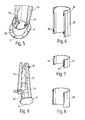
Fig. 5 is a perspective view of a detail of the lower half of the support with its corresponding half-clamp; -
Figs. 6, 7 and 8 depict in a perspective view the upper, intermediary and lower half-clamps, respectively; and -
Fig. 9 illustrates in a perspective view the shower having been folded for its ulterior packaging. - According to the drawings this shower comprises a longitudinal and slightly inclined support (1) being welded to a base (2) with holes (3) for the passage of the screws that are to be used for securedly fastening the shower to the ground, said shower being as well provided with an upper cover (2').
- The solar collector (4) is fitted to this support, said solar collector being made up by a black tube (5) being made of flexible plastics material and at each of its ends having fixedly attached to it a respective cap (6 and 7) with lateral orifice (8) for the water inflow and outflow.
- Two screws (9 and 10) are radially fixed in these caps and are used for upperly fitting the solar collector in a shiftable assembly in respective slits (11) being provided in the upper half (12) of the support (1) and for fitting said solar collector in respective notches (13) being provided in the lower half (14) of the support (1) where it comes to rest.
- These two halves (12 and 14) of the support (1) are fitted to each other with screws (15).
- The shower structure furthermore comprises three half-clamps (16, 17 and 18), the upper one and the intermediary one being fitted to the support in a removable assembly by means of hooks (19) being introduced into slits (20) being provided in the support (1), and the lower one being fixedly attached to this latter by means of welding.
- These half-clamps are laterally applied to the solar collector (4) in a loose manner in order to thus allow it to experience a free radial expansion.
- The support (1) will innerly comprise the hot and cold water pipes with the corresponding cocks (21, 22) and will upperly comprise the sprinkler or dripper (23). A quick-connection type coupling for the water is designated at (24).
Claims (3)
- A shower with solar collector comprising a longitudinal support (1) being provided with the fittings being characteristic of a shower, the solar collector (4) being made up by a black and flexible, tubular reservoir (5) being longitudinally fitted to said longitudinal support; characterised in that the solar collector (4) is fitted to the support (1) in such a way that it comes to rest at its lower end and has its upper end fitted in a shiftable assembly.
- A shower with solar collector, as per claim 1, characterised in that three half-clamps (16, 17 and 18) are laterally applied to the solar collector (4) and fitted to the support (1) at its two ends and in an intermediary region, at least part of said half-clamps being fitted in a removable assembly.
- A shower with solar collector, as per claim 1, characterised in that the support (1) is formed by two halves namely being an upper one (12) and a lower one (14), said two halves being adapted to be fitted (15) to each other.
Applications Claiming Priority (1)
| Application Number | Priority Date | Filing Date | Title |
|---|---|---|---|
| ES200701512U ES1066072Y (en) | 2007-07-13 | 2007-07-13 | SHOWER WITH SOLAR COLLECTOR |
Publications (2)
| Publication Number | Publication Date |
|---|---|
| EP2015001A2 true EP2015001A2 (en) | 2009-01-14 |
| EP2015001A3 EP2015001A3 (en) | 2016-05-18 |
Family
ID=38787237
Family Applications (1)
| Application Number | Title | Priority Date | Filing Date |
|---|---|---|---|
| EP08380208.2A Withdrawn EP2015001A3 (en) | 2007-07-13 | 2008-07-09 | A shower with solar collector |
Country Status (2)
| Country | Link |
|---|---|
| EP (1) | EP2015001A3 (en) |
| ES (1) | ES1066072Y (en) |
Cited By (3)
| Publication number | Priority date | Publication date | Assignee | Title |
|---|---|---|---|---|
| CN103017352A (en) * | 2012-11-30 | 2013-04-03 | 中国科学院理化技术研究所 | Soft solar heat collector |
| FR3077625A1 (en) * | 2018-02-02 | 2019-08-09 | Fabrice Curt | UNIVERSAL SOLAR TANK FOR SHOWER COLUMN |
| AT17375U1 (en) * | 2019-04-19 | 2022-02-15 | Nova Technica Int Ltd | Shower device with holding device for a decorative element |
Family Cites Families (4)
| Publication number | Priority date | Publication date | Assignee | Title |
|---|---|---|---|---|
| ES1045691Y (en) * | 2000-03-08 | 2001-10-01 | Metalast S A Soc Unipersonal | SHOWER |
| CH694216A5 (en) * | 2000-04-06 | 2004-09-30 | Peter Diener | Solar thermal shower for outdoor use. |
| AU2006202504A1 (en) * | 2005-06-10 | 2007-01-04 | Magic Pool Products Pty Limited | Outdoor shower |
| ES1065958Y (en) * | 2007-07-17 | 2008-07-01 | Metalast S A U | "SHOWER" |
-
2007
- 2007-07-13 ES ES200701512U patent/ES1066072Y/en not_active Expired - Fee Related
-
2008
- 2008-07-09 EP EP08380208.2A patent/EP2015001A3/en not_active Withdrawn
Cited By (3)
| Publication number | Priority date | Publication date | Assignee | Title |
|---|---|---|---|---|
| CN103017352A (en) * | 2012-11-30 | 2013-04-03 | 中国科学院理化技术研究所 | Soft solar heat collector |
| FR3077625A1 (en) * | 2018-02-02 | 2019-08-09 | Fabrice Curt | UNIVERSAL SOLAR TANK FOR SHOWER COLUMN |
| AT17375U1 (en) * | 2019-04-19 | 2022-02-15 | Nova Technica Int Ltd | Shower device with holding device for a decorative element |
Also Published As
| Publication number | Publication date |
|---|---|
| ES1066072U (en) | 2007-12-16 |
| EP2015001A3 (en) | 2016-05-18 |
| ES1066072Y (en) | 2008-06-01 |
Similar Documents
| Publication | Publication Date | Title |
|---|---|---|
| US4206748A (en) | Solar energy collector with collapsible supporting structure | |
| EP3147584B1 (en) | Liquid storage for storage of cold and warm liquids | |
| US20090095454A1 (en) | Drainpipe heat exchanger | |
| EP2015001A2 (en) | A shower with solar collector | |
| US20200003496A1 (en) | Heat exchangers that save energy by heat exchange between a fresh liquid and waste fluids | |
| US20130186388A1 (en) | Solar collector | |
| EP1947992B1 (en) | A shower heated by solar energy | |
| CN100412463C (en) | A kind of installation device of solar vacuum heat collecting tube | |
| CA2947772C (en) | Waste heat exchanger with thermal storage | |
| EP2017553B1 (en) | A shower | |
| DK201400140A1 (en) | Inlet stratification device | |
| CN207455008U (en) | Water heating pipe fittings structure | |
| CN201400909Y (en) | Water storage device capable of storing cold water and hot water simultaneously | |
| CN205618823U (en) | Double bracing formula elastic supporting tube card mechanism | |
| CA2626219C (en) | Drainpipe heat exchanger with heat storage | |
| JP2008175515A (en) | Vessel used in solar water heater | |
| CN206468843U (en) | A kind of sensitivity tap | |
| CN209893500U (en) | Floor heating water pipe | |
| CN206708419U (en) | It may move out the tap at the mouth of a river | |
| CA2583161A1 (en) | Waste heat exchanger | |
| CN206572762U (en) | A kind of heater inleting pipe | |
| CN201215397Y (en) | Solar showering device | |
| CN201209963Y (en) | solar water heater tank | |
| WO2017020913A1 (en) | Inlet stratification device | |
| Roman | Make and Test a Simple Solar Collector |
Legal Events
| Date | Code | Title | Description |
|---|---|---|---|
| PUAI | Public reference made under article 153(3) epc to a published international application that has entered the european phase |
Free format text: ORIGINAL CODE: 0009012 |
|
| AK | Designated contracting states |
Kind code of ref document: A2 Designated state(s): AT BE BG CH CY CZ DE DK EE ES FI FR GB GR HR HU IE IS IT LI LT LU LV MC MT NL NO PL PT RO SE SI SK TR |
|
| AX | Request for extension of the european patent |
Extension state: AL BA MK RS |
|
| PUAL | Search report despatched |
Free format text: ORIGINAL CODE: 0009013 |
|
| AK | Designated contracting states |
Kind code of ref document: A3 Designated state(s): AT BE BG CH CY CZ DE DK EE ES FI FR GB GR HR HU IE IS IT LI LT LU LV MC MT NL NO PL PT RO SE SI SK TR |
|
| AX | Request for extension of the european patent |
Extension state: AL BA MK RS |
|
| RIC1 | Information provided on ipc code assigned before grant |
Ipc: F24J 2/34 20060101AFI20160411BHEP Ipc: A47K 3/28 20060101ALI20160411BHEP Ipc: F24J 2/42 20060101ALI20160411BHEP |
|
| STAA | Information on the status of an ep patent application or granted ep patent |
Free format text: STATUS: THE APPLICATION HAS BEEN PUBLISHED |
|
| AKY | No designation fees paid | ||
| AXX | Extension fees paid |
Extension state: BA Extension state: AL Extension state: MK Extension state: RS |
|
| REG | Reference to a national code |
Ref country code: DE Ref legal event code: R108 |
|
| STAA | Information on the status of an ep patent application or granted ep patent |
Free format text: STATUS: THE APPLICATION IS DEEMED TO BE WITHDRAWN |
|
| 18D | Application deemed to be withdrawn |
Effective date: 20161119 |