EP2014914B1 - Wind power generating rotor blades utilizing inertial force, wind power generating apparatus using the rotor blades, and wind power generating system - Google Patents
Wind power generating rotor blades utilizing inertial force, wind power generating apparatus using the rotor blades, and wind power generating system Download PDFInfo
- Publication number
- EP2014914B1 EP2014914B1 EP07742852.2A EP07742852A EP2014914B1 EP 2014914 B1 EP2014914 B1 EP 2014914B1 EP 07742852 A EP07742852 A EP 07742852A EP 2014914 B1 EP2014914 B1 EP 2014914B1
- Authority
- EP
- European Patent Office
- Prior art keywords
- wind turbine
- support column
- turbine generator
- rotor blades
- power
- Prior art date
- Legal status (The legal status is an assumption and is not a legal conclusion. Google has not performed a legal analysis and makes no representation as to the accuracy of the status listed.)
- Active
Links
- 230000005540 biological transmission Effects 0.000 claims description 8
- 239000003990 capacitor Substances 0.000 claims description 2
- 239000000725 suspension Substances 0.000 description 9
- 238000010248 power generation Methods 0.000 description 8
- 239000004020 conductor Substances 0.000 description 6
- 239000002184 metal Substances 0.000 description 5
- 241000282414 Homo sapiens Species 0.000 description 4
- 238000012423 maintenance Methods 0.000 description 4
- 239000011347 resin Substances 0.000 description 4
- 229920005989 resin Polymers 0.000 description 4
- 239000004744 fabric Substances 0.000 description 3
- 239000000463 material Substances 0.000 description 3
- 230000002093 peripheral effect Effects 0.000 description 2
- 241000196324 Embryophyta Species 0.000 description 1
- 241000282412 Homo Species 0.000 description 1
- 241001465754 Metazoa Species 0.000 description 1
- 235000008331 Pinus X rigitaeda Nutrition 0.000 description 1
- 235000011613 Pinus brutia Nutrition 0.000 description 1
- 241000018646 Pinus brutia Species 0.000 description 1
- 238000010276 construction Methods 0.000 description 1
- 230000003247 decreasing effect Effects 0.000 description 1
- 230000000694 effects Effects 0.000 description 1
- 238000000638 solvent extraction Methods 0.000 description 1
- 238000003466 welding Methods 0.000 description 1
Images


Classifications
-
- F—MECHANICAL ENGINEERING; LIGHTING; HEATING; WEAPONS; BLASTING
- F03—MACHINES OR ENGINES FOR LIQUIDS; WIND, SPRING, OR WEIGHT MOTORS; PRODUCING MECHANICAL POWER OR A REACTIVE PROPULSIVE THRUST, NOT OTHERWISE PROVIDED FOR
- F03D—WIND MOTORS
- F03D3/00—Wind motors with rotation axis substantially perpendicular to the air flow entering the rotor
- F03D3/06—Rotors
- F03D3/062—Rotors characterised by their construction elements
-
- F—MECHANICAL ENGINEERING; LIGHTING; HEATING; WEAPONS; BLASTING
- F03—MACHINES OR ENGINES FOR LIQUIDS; WIND, SPRING, OR WEIGHT MOTORS; PRODUCING MECHANICAL POWER OR A REACTIVE PROPULSIVE THRUST, NOT OTHERWISE PROVIDED FOR
- F03D—WIND MOTORS
- F03D13/00—Assembly, mounting or commissioning of wind motors; Arrangements specially adapted for transporting wind motor components
- F03D13/20—Arrangements for mounting or supporting wind motors; Masts or towers for wind motors
-
- F—MECHANICAL ENGINEERING; LIGHTING; HEATING; WEAPONS; BLASTING
- F03—MACHINES OR ENGINES FOR LIQUIDS; WIND, SPRING, OR WEIGHT MOTORS; PRODUCING MECHANICAL POWER OR A REACTIVE PROPULSIVE THRUST, NOT OTHERWISE PROVIDED FOR
- F03D—WIND MOTORS
- F03D15/00—Transmission of mechanical power
- F03D15/10—Transmission of mechanical power using gearing not limited to rotary motion, e.g. with oscillating or reciprocating members
-
- F—MECHANICAL ENGINEERING; LIGHTING; HEATING; WEAPONS; BLASTING
- F03—MACHINES OR ENGINES FOR LIQUIDS; WIND, SPRING, OR WEIGHT MOTORS; PRODUCING MECHANICAL POWER OR A REACTIVE PROPULSIVE THRUST, NOT OTHERWISE PROVIDED FOR
- F03D—WIND MOTORS
- F03D3/00—Wind motors with rotation axis substantially perpendicular to the air flow entering the rotor
- F03D3/06—Rotors
- F03D3/061—Rotors characterised by their aerodynamic shape, e.g. aerofoil profiles
-
- F—MECHANICAL ENGINEERING; LIGHTING; HEATING; WEAPONS; BLASTING
- F03—MACHINES OR ENGINES FOR LIQUIDS; WIND, SPRING, OR WEIGHT MOTORS; PRODUCING MECHANICAL POWER OR A REACTIVE PROPULSIVE THRUST, NOT OTHERWISE PROVIDED FOR
- F03D—WIND MOTORS
- F03D9/00—Adaptations of wind motors for special use; Combinations of wind motors with apparatus driven thereby; Wind motors specially adapted for installation in particular locations
- F03D9/10—Combinations of wind motors with apparatus storing energy
- F03D9/11—Combinations of wind motors with apparatus storing energy storing electrical energy
-
- F—MECHANICAL ENGINEERING; LIGHTING; HEATING; WEAPONS; BLASTING
- F03—MACHINES OR ENGINES FOR LIQUIDS; WIND, SPRING, OR WEIGHT MOTORS; PRODUCING MECHANICAL POWER OR A REACTIVE PROPULSIVE THRUST, NOT OTHERWISE PROVIDED FOR
- F03D—WIND MOTORS
- F03D9/00—Adaptations of wind motors for special use; Combinations of wind motors with apparatus driven thereby; Wind motors specially adapted for installation in particular locations
- F03D9/20—Wind motors characterised by the driven apparatus
- F03D9/25—Wind motors characterised by the driven apparatus the apparatus being an electrical generator
-
- F—MECHANICAL ENGINEERING; LIGHTING; HEATING; WEAPONS; BLASTING
- F05—INDEXING SCHEMES RELATING TO ENGINES OR PUMPS IN VARIOUS SUBCLASSES OF CLASSES F01-F04
- F05B—INDEXING SCHEME RELATING TO WIND, SPRING, WEIGHT, INERTIA OR LIKE MOTORS, TO MACHINES OR ENGINES FOR LIQUIDS COVERED BY SUBCLASSES F03B, F03D AND F03G
- F05B2240/00—Components
- F05B2240/20—Rotors
- F05B2240/21—Rotors for wind turbines
- F05B2240/211—Rotors for wind turbines with vertical axis
- F05B2240/216—Rotors for wind turbines with vertical axis of the anemometer type
-
- F—MECHANICAL ENGINEERING; LIGHTING; HEATING; WEAPONS; BLASTING
- F05—INDEXING SCHEMES RELATING TO ENGINES OR PUMPS IN VARIOUS SUBCLASSES OF CLASSES F01-F04
- F05B—INDEXING SCHEME RELATING TO WIND, SPRING, WEIGHT, INERTIA OR LIKE MOTORS, TO MACHINES OR ENGINES FOR LIQUIDS COVERED BY SUBCLASSES F03B, F03D AND F03G
- F05B2240/00—Components
- F05B2240/20—Rotors
- F05B2240/30—Characteristics of rotor blades, i.e. of any element transforming dynamic fluid energy to or from rotational energy and being attached to a rotor
- F05B2240/31—Characteristics of rotor blades, i.e. of any element transforming dynamic fluid energy to or from rotational energy and being attached to a rotor of changeable form or shape
- F05B2240/313—Characteristics of rotor blades, i.e. of any element transforming dynamic fluid energy to or from rotational energy and being attached to a rotor of changeable form or shape with adjustable flow intercepting area
-
- F—MECHANICAL ENGINEERING; LIGHTING; HEATING; WEAPONS; BLASTING
- F05—INDEXING SCHEMES RELATING TO ENGINES OR PUMPS IN VARIOUS SUBCLASSES OF CLASSES F01-F04
- F05B—INDEXING SCHEME RELATING TO WIND, SPRING, WEIGHT, INERTIA OR LIKE MOTORS, TO MACHINES OR ENGINES FOR LIQUIDS COVERED BY SUBCLASSES F03B, F03D AND F03G
- F05B2250/00—Geometry
- F05B2250/20—Geometry three-dimensional
- F05B2250/24—Geometry three-dimensional ellipsoidal
- F05B2250/241—Geometry three-dimensional ellipsoidal spherical
-
- Y—GENERAL TAGGING OF NEW TECHNOLOGICAL DEVELOPMENTS; GENERAL TAGGING OF CROSS-SECTIONAL TECHNOLOGIES SPANNING OVER SEVERAL SECTIONS OF THE IPC; TECHNICAL SUBJECTS COVERED BY FORMER USPC CROSS-REFERENCE ART COLLECTIONS [XRACs] AND DIGESTS
- Y02—TECHNOLOGIES OR APPLICATIONS FOR MITIGATION OR ADAPTATION AGAINST CLIMATE CHANGE
- Y02E—REDUCTION OF GREENHOUSE GAS [GHG] EMISSIONS, RELATED TO ENERGY GENERATION, TRANSMISSION OR DISTRIBUTION
- Y02E10/00—Energy generation through renewable energy sources
- Y02E10/70—Wind energy
- Y02E10/728—Onshore wind turbines
-
- Y—GENERAL TAGGING OF NEW TECHNOLOGICAL DEVELOPMENTS; GENERAL TAGGING OF CROSS-SECTIONAL TECHNOLOGIES SPANNING OVER SEVERAL SECTIONS OF THE IPC; TECHNICAL SUBJECTS COVERED BY FORMER USPC CROSS-REFERENCE ART COLLECTIONS [XRACs] AND DIGESTS
- Y02—TECHNOLOGIES OR APPLICATIONS FOR MITIGATION OR ADAPTATION AGAINST CLIMATE CHANGE
- Y02E—REDUCTION OF GREENHOUSE GAS [GHG] EMISSIONS, RELATED TO ENERGY GENERATION, TRANSMISSION OR DISTRIBUTION
- Y02E10/00—Energy generation through renewable energy sources
- Y02E10/70—Wind energy
- Y02E10/74—Wind turbines with rotation axis perpendicular to the wind direction
-
- Y—GENERAL TAGGING OF NEW TECHNOLOGICAL DEVELOPMENTS; GENERAL TAGGING OF CROSS-SECTIONAL TECHNOLOGIES SPANNING OVER SEVERAL SECTIONS OF THE IPC; TECHNICAL SUBJECTS COVERED BY FORMER USPC CROSS-REFERENCE ART COLLECTIONS [XRACs] AND DIGESTS
- Y02—TECHNOLOGIES OR APPLICATIONS FOR MITIGATION OR ADAPTATION AGAINST CLIMATE CHANGE
- Y02E—REDUCTION OF GREENHOUSE GAS [GHG] EMISSIONS, RELATED TO ENERGY GENERATION, TRANSMISSION OR DISTRIBUTION
- Y02E70/00—Other energy conversion or management systems reducing GHG emissions
- Y02E70/30—Systems combining energy storage with energy generation of non-fossil origin
Definitions
- the present invention relates to a wind turbine generator, more specifically, a wind turbine generator that includes a support column and a rotor with multiple canvas blades attached to the support column, the support column detachably fixed to an inner part of a circular ring and provided with tapered end portions, and that can be rotated by even weak wind force and can also be rotated continuously by inertial force after the rotation.
- propeller wind turbines and Darrieus wind turbines are the mainstreams of the horizontal axis wind turbines and the vertical axis wind turbines, respectively.
- these types of wind turbines can only deliver their performance with a wind speed of 10 m/s or faster.
- a small wind turbine of this type rotates at 40 to 100 rpm.
- the rated speed needs to be 900 to 1,750 rpm. Accordingly, the wind turbine has to be equipped with a speed-increasing gear that is used to increase the rated speed 20 to 60 times.
- a disc or a brake is used for the control in strong winds to force the wind turbine to stop rotating, and this in turn causes an increase in price of the entire wind turbine.
- a small and inexpensive wind turbine that is capable of increasing the rated speed by using a gear even when the wind force is weak has been developed (Japanese Patent Application Publication No. 2005-320865 ).
- Savonius wind turbines In contrast, Savonius wind turbines, paddle wind turbines and rotating-blade wind turbines are examples of wind turbines capable of generating power by weak winds.
- Such wind turbines are drag type wind turbines, and operate efficiently when the tip speed ratio (the peripheral speed of rotor / wind speed) is small while having a disadvantage of decreasing in operating performance when the tip speed ratio is large.
- Japanese Patent Application Publication No. 2004-353637 discloses a "rotating-blade vertical axis wind turbine.”
- Japanese Patent Application Publication No. 2005-9415 discloses a "mechanism for automatically adjusting rotations of wind turbine.”
- "canvas blades made of flexible and strong canvas are provided, yard members are attached respectively to the front ends and the back ends of the canvas blades, the front yard members are attached to a doughnut-shaped front hub member, the back yard members are attached to a doughnut-shaped back hub member to form a radial pattern, a rotation shaft is inserted into the hub members so as to protrude from the hub members, speed control balancers are attached to the back hub member with the rotation shaft interposed between the speed control balancers, connecting rods parallel with the rotation shaft are connected to a slide cylinder integrated with the front hub member, a spring bearing is provided to the front end of the rotation shaft, a return spring is elastically provided between the slide cylinder and the spring bearing, a long spiral hole is formed in the slide cylinder, a lock pin implanted in the rotation shaft in a standing position is loosely fitted into the long spiral hole, and torque of the
- US 5997252 discloses a wind turbine generator rotor unit comprising a support column having a rod with an upper end portion and a lower end portion, a holder fixed to the support column and a plurality of rotor blades attached to the support column using the holder, wherein the rotor blades each include a plurality of first support frames extending from the frame so as to form a semi-electrical shape, and a central support frame supporting the first support frames and a sail attached to the frame so as to cover the frame unit.
- propeller wind turbines have been constructed in regions with strong winds.
- wind turbines of this type have the following disadvantages.
- a propeller wind turbine has a restriction that a support column for supporting the propeller needs to be strengthened rather than the propeller itself, which leads to an increase in construction cost.
- propeller wind turbines are constructed in a large site, they are more likely to be hit by lighting.
- propeller wind turbines make large wind noise since the blades constituting the propeller are made of metal or hard plastic.
- the blades when hit by a gust of strong wind, they might break into pieces, and the scattered pieces might hurt humans and animals.
- propeller wind turbines need to be constructed in a large and remote site.
- a starting motor is an essential for propeller wind turbines because of the following restriction.
- a separately-provided motor needs to be put into operation first to cause the propeller to rotate and to activate the power generation function in the meanwhile.
- the inventors of the present invention diligently carried out research to solve the above-described problems.
- the inventors succeeded in developing a new wind turbine generator having the following features and a wind turbine generator system using the wind turbine generator.
- a rotor can easily start rotating by small wind force (1 to 2 m/s or more) by using bowl-shaped rotor blades made of canvas, and once the rotor starts rotating, it can continuously rotate because of the inertia force.
- this wind turbine generator is inexpensive and can be constructed in a site having no power source.
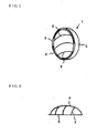
- Fig. 1 shows a basic shape of a rotor blade 1 used in a wind turbine generator of the present invention
- Fig. 2 is an illustration showing a structure of a frame unit shown in Fig. 1
- Fig. 3 is illustrations showing variations of a frame 2, and shapes for allowing a flywheel 8 to be sandwiched and fitted to a slot 50 (as shown in Fig. 7 or Fig. 8 ) are shown in Figs. 3a and 3b , respectively.
- the rotor blade 1 includes a frame unit 10.
- the frame unit 10 includes: the frame 2 having openings in a semicircular shape or a semielliptical shape, or a different shape such as a leaf shape or a comb shape; multiple first support frames 3 each provided in an extending manner from the frame 2 so as to form a semielliptical shape; and a central support frame 4 supporting the first support frames 3.
- the rotor blade 1 is fixed to a support column 7 with a holder 8 interposed therebetween, in such a manner that a string 6 is inserted to holes (not shown) formed in a peripheral portion of a sail 5 attached to the frame unit 10 so as to cover the frame unit 10, and is thus overall in a bowl shape expanding outwardly with a radius.
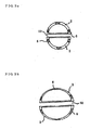
- the wind turbine generator of the present invention includes a rotor unit 100, a power generator 12 generating power by using torque of the rotor unit 100, and a power storage 13 storing power generated by the power generator 12, in a circular ring 9 detachably holding the end portions of the support column 7 as shown in Fig. 4 .
- the rotor unit 100 includes the support column 7, the flywheel 8 fixed to a central portion of the support column 7, and multiple rotor blades 1 attached to a circular disc of the flywheel 8.
- An example of the wind turbine generator of the present invention includes, as shown in Fig. 7 : the rotor unit 100 consisting of the circular ring 9 formed of a thin stainless plate with a width of 10 cm and holding the end portions of the support column 7, the support column 7 made of metal and detachably attached to the inside of the circular ring 9, the flywheel 8 made of metal and fixed to the central portion of the support column 7, and the multiple rotor blades 1 attached to the flywheel 8; the power generator 12 generating power by using torque of the rotor unit 100; and the power storage 13 storing power generated by the power generator 12.
- the support column 7 of the wind turbine generator of the present invention is a rod with the external diameter of each of the upper end portion and the lower end portion reduced toward the tip of the end portion. Accordingly, once this support column 7 starts rotating by the turning action of the rotor blades 1 attached to the flywheel 8, the rotation continues for a long time because of the inertial force as the rotation of a commercially-available gyro-top. This is because as the finer the end portions are formed, the less the resistance in the event of rotation becomes, which allows the rotation to continue for a long time.
- the flywheel 8 fixed to the support column 7 is a circular plate, and fixed to an approximately central portion of the support column 7 with upper and lower fasteners 14 and 15 as shown in Fig. 5 .
- the lower fastener 15 is a circular bearer fixed to the support column by welding
- the upper fastener 14 is one or more rectangle pines knocked and inserted into grooves 16 formed respectively in the support column 7 and the flywheel 8, to hold and fix the support column and the flywheel 8.
- the lower end portions of the support column 7 are inserted into fixing member main bodies 17 with adjusters 20, the fixing member main bodies 17 provided respectively on upper and lower central portions of the inner surface of the circular ring 9. Moreover, each of the lower end portions of the support column 7 is inserted into the inner portion of a fixing member 19 formed in a substantially conical shape in the corresponding fixing member main body 17, the fixing member 19 including multiple bearings 18 aligned along the conical shape.
- the rotation of the rotor unit 100 causes the support column 7 itself to rotate, and a rotation sensor (not shown) controls the rotation of the support column 7 to have a rated PRM of 700 to 2,000 in the event of rotation using the rotation sensor (not shown).
- the end portions of the support column 7 are inserted into the fixing member with the adjustors 20 including spring members provided inside the fixing member main bodies 17 to allow height adjustment, the fixing members each include the multiple bearings.
- the adjustors 20 include springs.
- a transmission mechanism is provided Near the lower end portion of the support column 7, a transmission mechanism is provided. As shown in Fig. 7 , in this transmission mechanism, a rotating pulley 24 is directly attached to the support column 7 to transmit the torque of the support column 7 to the power generator 12 through a transmission belt 25. Alternatively, gear wheels which mesh with each other can be used as a transmission mechanism.
- a protrusion serving as a lighting conductor is provided near the upper end portion of the support column 7, while a ground wire is provided so as to extend from near the lower end portion of the support column 7 to the underground, to let energy occurring when lighting strikes flow into the underground.
- a circular ring with multiple strings or chains attached thereto may be fitted to the protrusion serving as a lighting conductor to keep the support column 7 perpendicular.
- a rotation motor (not shown) can be provided as a means used to cause the rotor to start rotating in a case with no winds.
- a second wind turbine generator of the present invention includes a rotor unit 200, the circular ring 9 detachably holding the end portions of the support column, the power generator 12 generating power by using torque of the rotor unit 200, and the power storage 13 storing the power generated by the power generator 12.
- the rotor unit 200 includes the support column 7, the multiple rotor blades 1 fixed to the support column 7 by the fasteners 21 attached to the support column 7, and a circular fixing member 22 holding and fixing the circumferences of the rotor blades same as those shown in Fig. 7 .
- each of the rotor blades 1 is fixed to the support column 7 by the multiple fasteners 21 attached to the support column 7 beforehand.
- the circular fixing member 22 made of hard resin is attached to the circumference of the other end side of each of the rotor blades 1, and serves as a weight, which makes the rotation smooth.
- the circular fixing member 22 has recesses 23 made of hard resin and holding and fixing the outer frames of the rotor blades 1, in the inner circumferential surface.
- the outer circumferences of the rotor blades 1 are held and fixed by the recesses 23.
- commercial messages may be shown by using LED chips or the like, or a picture or a pattern may be printed.
- messages, a picture, or a pattern shown on the outer circumference of the circular fixing member 22 can be visually identified easily even from a distance.
- Means for operating the power generator 12 by using torque of the rotor is operated in the same manner as the first wind turbine generator of the present invention described above.
- a wind turbine generator system includes: frame units each consisting of the frame 2 in a semicircular shape, a semielliptical shape or a leaf shape, the multiple support frames 3 extending from the frame 2, and the central support frame 4 supporting the support frames 3; a rotor unit including the wind-power-generation rotor blades each consisting of the sail 5 attached to the frame unit so as to cover the frame unit; the circular ring 9 detachably holding the end portions of the support column; the power generator 12 generating power by using torque of the rotor unit; the power storage 13 storing the power generated by the power generator 12; and a power control unit 40 transmitting the power stored in the power storage 13 to a power system of a building.
- the rotor unit is either the rotor unit 100 including the support column 7, the flywheel 8 fixed to the central portion of the support column 7, and the multiple rotor blades 1 attached to the flywheel 8, or the rotor unit 200 including the support column 7, the multiple rotor blades 1 fixed by the fasteners 21 attached to the support column 7, and the circular fixing member 22 holding and fixing the outer circumferences of the rotor blades, and causes the support column to rotate.
- the power generator 12 generates power by rotating a rotor (not shown) of the power generator 12 linked to the support column 7 with the rotating pulley 24 interposed therebetween.
- the power generated by the power generator 12 is supplied to the power storage 13 through a rectifier (not shown), or directly from the power generator 12.
- the power control unit 40 includes a power convertor (not shown) which converts the power from the power storage 13 to have a voltage, a frequency and the like conforming with the standards of the power system, and which has necessary protection functions.
- the power storage 13 is formed of a secondary battery or an electric double-layer capacitor, which makes it possible to do maintenance by requiring as less human work as possible.
- a bottom portion of the circular ring 9 with the support column 7 and the rotor unit 100 provided therein is placed on and fixed to a mount 35.
- a fastener (not shown) which allows chains or strings to be fastened to the lighting conductor 34 provided on the upper portion of the circular ring 9 may also be provided to stabilize the circular ring 9 by pulling the circular ring 9 to the front, the back, the right and the left.
- the rotor with the rotor blades attached thereto rotates by receiving light winds (wind speed 1 to 2 m/s) blown from above, below, the right and the left.
- a design may be made to include a small motor (not shown) for making the support column rotatable at startup of the case of forcing the rotor to rotate at startup by a man-induced.operation.
- a rotation sensor (not shown) is attached to the support column 7 or the rotor blades 1 to measure the torque of the rotor unit, and to cause the power generation function to operate when the rated speed reaches a set value from 700 rpm to 2,000 rpm.
- the rotor unit In strong winds, the rotor unit is removed by a man-induced operation because the rotor can be detached easily, or, when the man-induced operation is not possible, fasteners may be separately provided in such positions that the fasteners can sandwich the support column, to force the rotation of the support column to stop rotating when the wind speed measured by the anemometer exceeds a predetermined wind speed value.
- a wind power apparatus not part of the present invention includes, as shown in Fig. 10 and Fig. 11 : a rotor unit 300 consisting of a circular suspension member 26 having an opening in the bottom, multiple support bars 27 supporting the suspension member, and a circular holder 29 holding one end portion of each of multiple rotor blades 28 suspended from the suspension member 26; a rotation stopper 30 forcing the rotor unit to stop rotating; a power generator 31 generating power by using torque of the circular holder; and a power storage 32 storing the power generated by the power generator.
- the circular suspension member 26 has an opening in the bottom, and the upper part of the opening is in a substantially circular shape. This allows the spherical rotor blades to rotate.
- the power generator 31 is coupled with a pinion 32 for the power generator. Accordingly, when the power generation pinion 33 is rotated by the torque of the circular holder 29, a rotor (not shown) of the power generator 31 coupled with the pinion 33 is rotated, and power is generated by the action of a permanent magnet, for example.
- a commercially available alternating-current generator or direct-current generator may alternatively be used as the power generator.
- the rotation stopper 30 is connected to an anemometer (not shown), and includes a pair of sandwiching members (not shown) capable of stopping the rotation by sandwiching the circular holder 29 from the right and the left in strong winds.
- Another wind turbine generator system not part of the present invention includes: the rotor unit 300 consisting of the circular suspension member 26 having an opening in the bottom, the multiple support bars 27 supporting the suspension member, and the circular holder 29 holding one end portion of each of the multiple rotor blades 28 suspended from the suspension member 27; the power generator 31 generating power by using torque of the circular holder 29; the power storage 32 storing the power generated by the power generator; and a power control unit 40 transmitting the power stored in the power storage 32 to a power system of a building.
- the circular suspension member has an opening in the bottom, and the upper part of the opening is in a substantially circular shape, which allows the spherical rotor blades to rotate.
- the power generator is coupled with a pinion for the power generator.
- the power control unit includes a power convertor which converts the power from the power storage to have a voltage, a frequency and the like conforming with the standards of the power system, and which has necessary protection functions.
- the frames and the support frames of the rotor blades used in the wind turbine generator of the present invention is preferably made of a metal or resin material having a certain degree of strength.
- the sails attached to the frame units are preferably made of a strong cloth material used for marine sails or a strong cloth material used for parachutes for heavy drop.
- a wind turbine generator of the present invention uses rotor blades having a structure that the sails of the rotor blades can be folded in strong winds, as shown in Fig. 12 and Fig. 13 .
- the rotation shaft in this example is provided with multiple longitudinal rails.
- Wires provided to end portions of each of the rotor blades are moved by servomotors 61 provided on the outer surface of an outer frame fixing member, and the rotor blades are thereby folded.
- a sensor (not shown) causes the servomotors 61 to operate, on the basis of a value showing strong winds with a wind speed of 25 m or more measured by an anemometer 60.
- wires 62 attached to the end portions of each of the rotor blades change while folding the rotor blades from the end portions.
- the rotation shaft is held by three bearing housings 63 at the top, on top of a base, and at the bottom of the base.
- a shaft stopper ring 64 is attached so as to be in connection with the housing disposed on top of the base to stop the rotations of the outer frame and the rotation shaft in strong winds.
- a V-belt pulley 66 is disposed along the rotation shaft.
- the pulley 66 is configured to rotate, by using a belt (not shown), a small pulley 67 which is disposed so as to face the pulley 66 and which operates a power generator 68.
- multiple bearings (not shown) are buried into the inner circumference surfaces of the bearing housings so as to be in contact with the rotation shaft surface to facilitate the rotation of the rotation shaft.
- the wind turbine generator of the present invention is a sectional wind turbine generator that can easily be constructed on the roof of a mid-rise/high-rise building as well as in a large site such as a green field with few plants or a desert. In addition, maintenance can be done easily because the rotor blades can be replaced individually.
- a lighting conductor can be disposed in the center of the circular ring to let current occurring when lighting strikes flow into the underground. With this lighting conductor, damage to the rotor unit and the like can be prevented.
- the rotor blades and the support column can be assembled at a height of approximately several meters above ground, when the rotor blades and the like are installed. Accordingly, a machine such as a large-size crane is not required in the event of a failure, unlike a conventional propeller wind turbine; hence, the wind turbine generator of the present invention can easily be constructed even in a place which a machine such as an automobile is difficult to enter.
- the wind-power-generation rotor blades each have a circular or elliptic opening and a sail with a bowl-shaped radius. With such blades, even in light winds from any direction, above, below, the right or the left, the rotor unit can easily be rotated by receiving the winds by the entire blades. Moreover, once the rotor unit starts rotating, the support column serving as a support shaft continuously rotates at a rated speed from 700 rpm to 2,000 rpm by using the inertial force.
- the wind turbine generator system of the present invention can be remotely operated. Accordingly, this system is especially preferable for the operation in a place with few workers and the like.
- the rotor blades used in the wind turbine generator of the present invention has a structure that enables a folded state in strong winds to avoid receiving strong winds.
Description
- The present invention relates to a wind turbine generator, more specifically, a wind turbine generator that includes a support column and a rotor with multiple canvas blades attached to the support column, the support column detachably fixed to an inner part of a circular ring and provided with tapered end portions, and that can be rotated by even weak wind force and can also be rotated continuously by inertial force after the rotation.
- In conventional wind power generation, propeller wind turbines and Darrieus wind turbines are the mainstreams of the horizontal axis wind turbines and the vertical axis wind turbines, respectively. However, it is said that these types of wind turbines can only deliver their performance with a wind speed of 10 m/s or faster.
- Especially in wind power generation using propeller wind turbines, it has been inevitable that the entire wind turbine results in being large in size due to the following reason. A small wind turbine of this type rotates at 40 to 100 rpm. However, to use such a small wind turbine as a commercial wind turbine, the rated speed needs to be 900 to 1,750 rpm. Accordingly, the wind turbine has to be equipped with a speed-increasing gear that is used to increase the rated
speed 20 to 60 times. - In addition, a disc or a brake is used for the control in strong winds to force the wind turbine to stop rotating, and this in turn causes an increase in price of the entire wind turbine. To improve these situations, a small and inexpensive wind turbine that is capable of increasing the rated speed by using a gear even when the wind force is weak has been developed (Japanese Patent Application Publication No.
2005-320865 - In contrast, Savonius wind turbines, paddle wind turbines and rotating-blade wind turbines are examples of wind turbines capable of generating power by weak winds. Such wind turbines are drag type wind turbines, and operate efficiently when the tip speed ratio (the peripheral speed of rotor / wind speed) is small while having a disadvantage of decreasing in operating performance when the tip speed ratio is large.
- As a wind turbine for addressing these disadvantages, Japanese Patent Application Publication No.
2004-353637 - Japanese Patent Application Publication No.
2005-9415 -
Patent Document 1 Japanese Patent Application Publication No2005-320865 -
Patent Document 2 Japanese Patent Application Publication No2004-353637 -
Patent Document 3 Japanese Patent Application Publication No2005-9415 -
US 5997252 discloses a wind turbine generator rotor unit comprising a support column having a rod with an upper end portion and a lower end portion, a holder fixed to the support column and a plurality of rotor blades attached to the support column using the holder, wherein the rotor blades each include a plurality of first support frames extending from the frame so as to form a semi-electrical shape, and a central support frame supporting the first support frames and a sail attached to the frame so as to cover the frame unit. - Recently, a lot of propeller wind turbines have been constructed in regions with strong winds. However, wind turbines of this type have the following disadvantages. A propeller wind turbine has a restriction that a support column for supporting the propeller needs to be strengthened rather than the propeller itself, which leads to an increase in construction cost. Moreover, since propeller wind turbines are constructed in a large site, they are more likely to be hit by lighting.
- Furthermore, propeller wind turbines make large wind noise since the blades constituting the propeller are made of metal or hard plastic. In addition, when the blades are hit by a gust of strong wind, they might break into pieces, and the scattered pieces might hurt humans and animals. Hence, there is also a location problem that propeller wind turbines need to be constructed in a large and remote site.
- Moreover, a starting motor is an essential for propeller wind turbines because of the following restriction. To cause the propeller to rotate at startup or in light winds, a separately-provided motor needs to be put into operation first to cause the propeller to rotate and to activate the power generation function in the meanwhile.
- On the other hand, in the above-described case of using canvas blades made of canvas, unlike the case of using blades made of metal or hard plastic, the blades do not brake into pieces which prevent the pieces to be scattered. However, disadvantageously, such blades might not rotate depending on the wind direction.
- The inventors of the present invention diligently carried out research to solve the above-described problems. Through the research, the inventors succeeded in developing a new wind turbine generator having the following features and a wind turbine generator system using the wind turbine generator. In this wind turbine generator, a rotor can easily start rotating by small wind force (1 to 2 m/s or more) by using bowl-shaped rotor blades made of canvas, and once the rotor starts rotating, it can continuously rotate because of the inertia force. Moreover, this wind turbine generator is inexpensive and can be constructed in a site having no power source.
- The different aspects of the invention are defined by the attached claims.
-
-
Fig. 1 is a perspective view of a rotor blade for a wind turbine generator according to the present invention. -
Fig. 2 is an explanatory view showing a configuration of a frame unit inFig. 1 . -
Fig. 3 is explanatory views showing variations of a frame. -
Fig. 4 is a perspective view of an external view of a circular ring according to the present invention. -
Fig. 5 is a cross-sectional view showing fasteners fastening a flywheel according to the present invention. -
Fig. 6 is an explanatory view showing a mechanism for rotating a support column according to the present invention. -
Fig. 7 is an explanatory view for explaining a wind turbine generator system according to the present invention. -
Fig. 8 is a perspective view of a rotor according to the present invention. -
Fig. 9 is a perspective view of another rotor according to the present invention. -
Fig. 10 is a perspective view of a rotor not part of the present invention. -
Fig. 11 is an explanatory view for explaining a wind turbine generator system not part of the present invention. -
Fig. 12 is an explanatory view for explaining still another wind turbine generator system according to the present invention. -
Fig. 13 is a side view ofFig. 12 . -
- 1
- rotor blade
- 2
- frame
- 3
- support frame
- 4
- central support frame
- 5
- sail
- 6
- string
- 7
- support column
- 8
- flywheel
- 9
- circular ring
- 100, 200, 300
- rotor unit
- 12
- power generator
- 13
- power storage
- 14
- upper fastener (wedge-shaped pin)
- 15
- lower fastener (bearer)
- 16
- groove
- 17
- fixing member main body
- 18
- bearing
- 19
- fixing member
- 20
- adjustor
- 21
- fastener
- 22
- circular fixing member (holder)
- 23
- recess
- 24
- rotating pulley
- 25
- transmission belt
- 26
- circular suspension member
- 27
- support bar
- 28
- rotor blade
- 29
- circular holder
- 30
- rotation stopper
- 31
- power generator
- 32
- power storage
- 33
- pinion for power generator
- 34
- lighting conductor
- 35
- mount
- 40
- power control unit
- 50
- slot
- 60
- anemometer
- 61
- servomotor
- 62
- wire
- 63
- housing
- 64
- shaft stopper ring
- 65
- base
- 66
- V-belt pulley
- 67
- small pulley
- Detailed description will be given below of the present invention on the basis of the drawings. However, the scope of the present invention is not limited to the description.
-
Fig. 1 shows a basic shape of arotor blade 1 used in a wind turbine generator of the present invention, andFig. 2 is an illustration showing a structure of a frame unit shown inFig. 1 .Fig. 3 is illustrations showing variations of aframe 2, and shapes for allowing aflywheel 8 to be sandwiched and fitted to a slot 50 (as shown inFig. 7 orFig. 8 ) are shown inFigs. 3a and 3b , respectively. - The
rotor blade 1 includes a frame unit 10. As shown inFig. 1 and Fig. 2 , the frame unit 10 includes: theframe 2 having openings in a semicircular shape or a semielliptical shape, or a different shape such as a leaf shape or a comb shape; multiple first support frames 3 each provided in an extending manner from theframe 2 so as to form a semielliptical shape; and a central support frame 4 supporting the first support frames 3. Therotor blade 1 is fixed to asupport column 7 with aholder 8 interposed therebetween, in such a manner that astring 6 is inserted to holes (not shown) formed in a peripheral portion of a sail 5 attached to the frame unit 10 so as to cover the frame unit 10, and is thus overall in a bowl shape expanding outwardly with a radius. - As the holder, either the
flywheel 8 partitioning the rotor blades as shown inFig. 8 and Fig. 9 orfasteners 21 directly attached to the support column are used. - As shown in
Fig. 7 , the wind turbine generator of the present invention includes arotor unit 100, apower generator 12 generating power by using torque of therotor unit 100, and a power storage 13 storing power generated by thepower generator 12, in acircular ring 9 detachably holding the end portions of thesupport column 7 as shown inFig. 4 . Therotor unit 100 includes thesupport column 7, theflywheel 8 fixed to a central portion of thesupport column 7, andmultiple rotor blades 1 attached to a circular disc of theflywheel 8. - An example of the wind turbine generator of the present invention includes, as shown in
Fig. 7 : therotor unit 100 consisting of thecircular ring 9 formed of a thin stainless plate with a width of 10 cm and holding the end portions of thesupport column 7, thesupport column 7 made of metal and detachably attached to the inside of thecircular ring 9, theflywheel 8 made of metal and fixed to the central portion of thesupport column 7, and themultiple rotor blades 1 attached to theflywheel 8; thepower generator 12 generating power by using torque of therotor unit 100; and the power storage 13 storing power generated by thepower generator 12. - The
support column 7 of the wind turbine generator of the present invention is a rod with the external diameter of each of the upper end portion and the lower end portion reduced toward the tip of the end portion. Accordingly, once thissupport column 7 starts rotating by the turning action of therotor blades 1 attached to theflywheel 8, the rotation continues for a long time because of the inertial force as the rotation of a commercially-available gyro-top. This is because as the finer the end portions are formed, the less the resistance in the event of rotation becomes, which allows the rotation to continue for a long time. - The
flywheel 8 fixed to thesupport column 7 is a circular plate, and fixed to an approximately central portion of thesupport column 7 with upper andlower fasteners 14 and 15 as shown inFig. 5 . Here, the lower fastener 15 is a circular bearer fixed to the support column by welding, and theupper fastener 14 is one or more rectangle pines knocked and inserted intogrooves 16 formed respectively in thesupport column 7 and theflywheel 8, to hold and fix the support column and theflywheel 8. - The lower end portions of the
support column 7 are inserted into fixing membermain bodies 17 withadjusters 20, the fixing membermain bodies 17 provided respectively on upper and lower central portions of the inner surface of thecircular ring 9. Moreover, each of the lower end portions of thesupport column 7 is inserted into the inner portion of a fixingmember 19 formed in a substantially conical shape in the corresponding fixing membermain body 17, the fixingmember 19 includingmultiple bearings 18 aligned along the conical shape. With this structure, the rotation of therotor unit 100 causes thesupport column 7 itself to rotate, and a rotation sensor (not shown) controls the rotation of thesupport column 7 to have a rated PRM of 700 to 2,000 in the event of rotation using the rotation sensor (not shown). - To attach the
support column 7 detachably to the inside of thecircular ring 9, the end portions of thesupport column 7 are inserted into the fixing member with theadjustors 20 including spring members provided inside the fixing membermain bodies 17 to allow height adjustment, the fixing members each include the multiple bearings. Theadjustors 20 include springs. - Near the lower end portion of the
support column 7, a transmission mechanism is provided. As shown inFig. 7 , in this transmission mechanism, a rotatingpulley 24 is directly attached to thesupport column 7 to transmit the torque of thesupport column 7 to thepower generator 12 through atransmission belt 25. Alternatively, gear wheels which mesh with each other can be used as a transmission mechanism. - Moreover, a protrusion serving as a lighting conductor is provided near the upper end portion of the
support column 7, while a ground wire is provided so as to extend from near the lower end portion of thesupport column 7 to the underground, to let energy occurring when lighting strikes flow into the underground. In addition, a circular ring with multiple strings or chains attached thereto (not shown) may be fitted to the protrusion serving as a lighting conductor to keep thesupport column 7 perpendicular. - In the present invention, a rotation motor (not shown) can be provided as a means used to cause the rotor to start rotating in a case with no winds.
- A second wind turbine generator of the present invention includes a
rotor unit 200, thecircular ring 9 detachably holding the end portions of the support column, thepower generator 12 generating power by using torque of therotor unit 200, and the power storage 13 storing the power generated by thepower generator 12. As shown inFig. 9 , therotor unit 200 includes thesupport column 7, themultiple rotor blades 1 fixed to thesupport column 7 by thefasteners 21 attached to thesupport column 7, and acircular fixing member 22 holding and fixing the circumferences of the rotor blades same as those shown inFig. 7 . - In this example, as shown in
Fig. 9 , one end of each of therotor blades 1 is fixed to thesupport column 7 by themultiple fasteners 21 attached to thesupport column 7 beforehand. Moreover, the circular fixingmember 22 made of hard resin is attached to the circumference of the other end side of each of therotor blades 1, and serves as a weight, which makes the rotation smooth. - Here, the circular fixing
member 22 hasrecesses 23 made of hard resin and holding and fixing the outer frames of therotor blades 1, in the inner circumferential surface. Thus, the outer circumferences of therotor blades 1 are held and fixed by therecesses 23. In addition, on the outer circumference of the circular fixingmember 22 made of hard resin, commercial messages may be shown by using LED chips or the like, or a picture or a pattern may be printed. Thus, messages, a picture, or a pattern shown on the outer circumference of the circular fixingmember 22 can be visually identified easily even from a distance. - Means for operating the
power generator 12 by using torque of the rotor is operated in the same manner as the first wind turbine generator of the present invention described above. - A wind turbine generator system according to the present invention includes: frame units each consisting of the
frame 2 in a semicircular shape, a semielliptical shape or a leaf shape, the multiple support frames 3 extending from theframe 2, and the central support frame 4 supporting the support frames 3; a rotor unit including the wind-power-generation rotor blades each consisting of the sail 5 attached to the frame unit so as to cover the frame unit; thecircular ring 9 detachably holding the end portions of the support column; thepower generator 12 generating power by using torque of the rotor unit; the power storage 13 storing the power generated by thepower generator 12; and a power control unit 40 transmitting the power stored in the power storage 13 to a power system of a building. The rotor unit is either therotor unit 100 including thesupport column 7, theflywheel 8 fixed to the central portion of thesupport column 7, and themultiple rotor blades 1 attached to theflywheel 8, or therotor unit 200 including thesupport column 7, themultiple rotor blades 1 fixed by thefasteners 21 attached to thesupport column 7, and the circular fixingmember 22 holding and fixing the outer circumferences of the rotor blades, and causes the support column to rotate. Thepower generator 12 generates power by rotating a rotor (not shown) of thepower generator 12 linked to thesupport column 7 with the rotatingpulley 24 interposed therebetween. The power generated by thepower generator 12 is supplied to the power storage 13 through a rectifier (not shown), or directly from thepower generator 12. Moreover, the power control unit 40 includes a power convertor (not shown) which converts the power from the power storage 13 to have a voltage, a frequency and the like conforming with the standards of the power system, and which has necessary protection functions. - Here, the power storage 13 is formed of a secondary battery or an electric double-layer capacitor, which makes it possible to do maintenance by requiring as less human work as possible.
- A bottom portion of the
circular ring 9 with thesupport column 7 and therotor unit 100 provided therein is placed on and fixed to amount 35. Alternatively, a fastener (not shown) which allows chains or strings to be fastened to the lighting conductor 34 provided on the upper portion of thecircular ring 9 may also be provided to stabilize thecircular ring 9 by pulling thecircular ring 9 to the front, the back, the right and the left. - In this system of the present invention, the rotor with the rotor blades attached thereto rotates by receiving light winds (
wind speed 1 to 2 m/s) blown from above, below, the right and the left. Here, a design may be made to include a small motor (not shown) for making the support column rotatable at startup of the case of forcing the rotor to rotate at startup by a man-induced.operation. - In this system, a rotation sensor (not shown) is attached to the
support column 7 or therotor blades 1 to measure the torque of the rotor unit, and to cause the power generation function to operate when the rated speed reaches a set value from 700 rpm to 2,000 rpm. - In strong winds, the rotor unit is removed by a man-induced operation because the rotor can be detached easily, or, when the man-induced operation is not possible, fasteners may be separately provided in such positions that the fasteners can sandwich the support column, to force the rotation of the support column to stop rotating when the wind speed measured by the anemometer exceeds a predetermined wind speed value.
- A wind power apparatus not part of the present invention includes, as shown in
Fig. 10 and Fig. 11 : a rotor unit 300 consisting of acircular suspension member 26 having an opening in the bottom, multiple support bars 27 supporting the suspension member, and acircular holder 29 holding one end portion of each ofmultiple rotor blades 28 suspended from thesuspension member 26; arotation stopper 30 forcing the rotor unit to stop rotating; a power generator 31 generating power by using torque of the circular holder; and apower storage 32 storing the power generated by the power generator. - Here, the
circular suspension member 26 has an opening in the bottom, and the upper part of the opening is in a substantially circular shape. This allows the spherical rotor blades to rotate. - The power generator 31 is coupled with a
pinion 32 for the power generator. Accordingly, when thepower generation pinion 33 is rotated by the torque of thecircular holder 29, a rotor (not shown) of the power generator 31 coupled with thepinion 33 is rotated, and power is generated by the action of a permanent magnet, for example. In this case, a commercially available alternating-current generator or direct-current generator may alternatively be used as the power generator. - The
rotation stopper 30 is connected to an anemometer (not shown), and includes a pair of sandwiching members (not shown) capable of stopping the rotation by sandwiching thecircular holder 29 from the right and the left in strong winds. - Another wind turbine generator system not part of the present invention includes: the rotor unit 300 consisting of the
circular suspension member 26 having an opening in the bottom, the multiple support bars 27 supporting the suspension member, and thecircular holder 29 holding one end portion of each of themultiple rotor blades 28 suspended from thesuspension member 27; the power generator 31 generating power by using torque of thecircular holder 29; thepower storage 32 storing the power generated by the power generator; and a power control unit 40 transmitting the power stored in thepower storage 32 to a power system of a building. Here, the circular suspension member has an opening in the bottom, and the upper part of the opening is in a substantially circular shape, which allows the spherical rotor blades to rotate. The power generator is coupled with a pinion for the power generator. Accordingly, when the power generation pinion is rotated by the torque of the circular holder, a rotor of the power generator coupled with the pinion is rotated, and power is generated by the action of a permanent magnet, or by using a commercially available alternating-current generator or direct-current generator. The power generated by the power generator is supplied to the power storage through a rectifier, or directly from the power generator. Moreover, the power control unit includes a power convertor which converts the power from the power storage to have a voltage, a frequency and the like conforming with the standards of the power system, and which has necessary protection functions. - The frames and the support frames of the rotor blades used in the wind turbine generator of the present invention is preferably made of a metal or resin material having a certain degree of strength. Moreover, the sails attached to the frame units are preferably made of a strong cloth material used for marine sails or a strong cloth material used for parachutes for heavy drop.
- A wind turbine generator of the present invention uses rotor blades having a structure that the sails of the rotor blades can be folded in strong winds, as shown in
Fig. 12 and Fig. 13 . - Here, the rotation shaft in this example is provided with multiple longitudinal rails. Wires provided to end portions of each of the rotor blades (blades made of cloth) are moved by servomotors 61 provided on the outer surface of an outer frame fixing member, and the rotor blades are thereby folded. For example, a sensor (not shown) causes the servomotors 61 to operate, on the basis of a value showing strong winds with a wind speed of 25 m or more measured by an
anemometer 60. Thereby, wires 62 attached to the end portions of each of the rotor blades change while folding the rotor blades from the end portions. - In this example, the rotation shaft is held by three bearing
housings 63 at the top, on top of a base, and at the bottom of the base. A shaft stopper ring 64 is attached so as to be in connection with the housing disposed on top of the base to stop the rotations of the outer frame and the rotation shaft in strong winds. - With this configuration, the rotor blades in the folded state do not rotate and let the strong winds pass. Accordingly, no maintenance due to strong winds is required; thus, this wind turbine generator is valuable when used in a region with few maintenance personnel.
- When the wind speed value measured by the anemometer indicates 25 m or smaller, on the other hand, the shaft stopper ring 64 is released. Thereby, the rotor blades start to open by the action of the servomotors 61, and return to the original state.
- Inside the
base 65, a V-belt pulley 66 is disposed along the rotation shaft. The pulley 66 is configured to rotate, by using a belt (not shown), asmall pulley 67 which is disposed so as to face the pulley 66 and which operates apower generator 68. - Here, multiple bearings (not shown) are buried into the inner circumference surfaces of the bearing housings so as to be in contact with the rotation shaft surface to facilitate the rotation of the rotation shaft.
- The wind turbine generator of the present invention is a sectional wind turbine generator that can easily be constructed on the roof of a mid-rise/high-rise building as well as in a large site such as a green field with few plants or a desert. In addition, maintenance can be done easily because the rotor blades can be replaced individually.
- In the case of constructing the wind turbine generator in a large site, a lighting conductor can be disposed in the center of the circular ring to let current occurring when lighting strikes flow into the underground. With this lighting conductor, damage to the rotor unit and the like can be prevented.
- The rotor blades and the support column can be assembled at a height of approximately several meters above ground, when the rotor blades and the like are installed. Accordingly, a machine such as a large-size crane is not required in the event of a failure, unlike a conventional propeller wind turbine; hence, the wind turbine generator of the present invention can easily be constructed even in a place which a machine such as an automobile is difficult to enter.
- While having a simple structure, the wind-power-generation rotor blades each have a circular or elliptic opening and a sail with a bowl-shaped radius. With such blades, even in light winds from any direction, above, below, the right or the left, the rotor unit can easily be rotated by receiving the winds by the entire blades. Moreover, once the rotor unit starts rotating, the support column serving as a support shaft continuously rotates at a rated speed from 700 rpm to 2,000 rpm by using the inertial force.
- Moreover, commercial messages or pictures can be drawn on the rotor blades used in the present invention and the circular fixing member for holding and fixing the peripheries of the rotor blades, to enhance the advertising effects. Besides, various advertisements can be shown in accordance with the rotation speed.
- Furthermore, the wind turbine generator system of the present invention can be remotely operated. Accordingly, this system is especially preferable for the operation in a place with few workers and the like.
- When the wind speed measured by the anemometer is equal to or larger than a predetermined value, the wires are moved by the working of the power transmission motor and the canvas blades connected to the wires can thereby be folded frontward and backward. Thus, the rotor blades used in the wind turbine generator of the present invention has a structure that enables a folded state in strong winds to avoid receiving strong winds.
Claims (9)
- A wind turbine generator rotor unit comprising:a support column (7) being a rod having an upper end portion and a lower end portion each reduced in external diameter toward the tip of the end portion;a circular ring (9) holding the end portions of the support column so that the support column itself rotates;a holder fixed to the support column; anda plurality of rotor blades (1) attached to the support column (7) by using the holder,the wind turbine generator rotor unit wherein the rotor blades each include:a frame unit including a frame (2) having an opening, a plurality of first support frames (3) extending from the frame so as to form semielliptical shape, and a central support frame (4) supporting the first support frames; anda sail (5) attached to the frame unit so as to cover the frame unit.
- The wind turbine generator rotor unit according to claim 1, wherein
the holder (22) is a circular plate fixed to a central portion of the support column, and
the rotor blades (1) are each attached to the holder by sandwiching the holder. - The wind turbine generator rotor unit according to claim 1, wherein the holder (22) is a circular fixing member holding and fixing peripheries of the rotor blades.
- The wind turbine generator rotor unit according to any one of claims 1 to 3, wherein
fixing member main bodies (17) are provided respectively on upper and lower central portions of an inner surface of the circular ring, and
the end portions of the support column (7) are fitted respectively to the insides of the fixing member main bodies by using adjustors which enable height adjustment. - The wind turbine generator rotor unit according to any one of claims 1 to 4, wherein the rotor blades have a structure making the rotor blades foldable frontward and backward.
- A wind turbine generator comprising, at least:the wind turbine generator rotor unit according to any one of claims 1 to 5;a power generator (12) generating power by using torque of the wind turbine generator rotor unit; anda transmission mechanism transmitting torque of the support column of the wind turbine generator rotor unit to the power generator.
- The wind turbine generator according to claim 6, further comprising a power storage (13) storing power generated by the power generator.
- The wind turbine generator according to claim 7, wherein the power storage (13) is formed of any one of a secondary battery and an electric double-layer capacitor.
- The wind turbine generator according to any one of claims 6 to 8, wherein the support column serving as a rotation shaft of the wind turbine generator rotor unit is provided with a plurality of longitudinal rails, and wires provided to end portions of each of the rotor blades are moved by a servomotor provided to one of the end portions of the support column, so that the rotor blades are folded.
Applications Claiming Priority (3)
| Application Number | Priority Date | Filing Date | Title |
|---|---|---|---|
| JP2006145911 | 2006-04-25 | ||
| JP2007052025A JP5155574B2 (en) | 2006-04-25 | 2007-02-01 | Rotating blade for wind power generation using inertial force, wind power generation apparatus using the same, and wind power generation system |
| PCT/JP2007/059417 WO2007126129A1 (en) | 2006-04-25 | 2007-04-25 | Wind power generating rotor blades utilizing inertial force, wind power generating apparatus using the rotor blades, and wind power generating system |
Publications (3)
| Publication Number | Publication Date |
|---|---|
| EP2014914A1 EP2014914A1 (en) | 2009-01-14 |
| EP2014914A4 EP2014914A4 (en) | 2013-03-13 |
| EP2014914B1 true EP2014914B1 (en) | 2014-03-26 |
Family
ID=38655645
Family Applications (1)
| Application Number | Title | Priority Date | Filing Date |
|---|---|---|---|
| EP07742852.2A Active EP2014914B1 (en) | 2006-04-25 | 2007-04-25 | Wind power generating rotor blades utilizing inertial force, wind power generating apparatus using the rotor blades, and wind power generating system |
Country Status (4)
| Country | Link |
|---|---|
| US (1) | US7980823B2 (en) |
| EP (1) | EP2014914B1 (en) |
| JP (1) | JP5155574B2 (en) |
| WO (1) | WO2007126129A1 (en) |
Families Citing this family (24)
| Publication number | Priority date | Publication date | Assignee | Title |
|---|---|---|---|---|
| JP5155574B2 (en) * | 2006-04-25 | 2013-03-06 | 赤 嶺 辰 実 | Rotating blade for wind power generation using inertial force, wind power generation apparatus using the same, and wind power generation system |
| KR100707132B1 (en) * | 2006-05-26 | 2007-04-13 | 나경자 | Rotor blade for a wind power generator |
| FR2927375A1 (en) * | 2008-02-12 | 2009-08-14 | Rudolf Kalman | Vertical axis wind turbine i.e. Darrieus wind turbine, has concentric circular cradles arranged between ends of mast and connected by arches that support sail-wings, where assembly of sail-wings and cradles is subsided along mast as desired |
| US20100060009A1 (en) * | 2008-09-09 | 2010-03-11 | Shimon Elmaleh | Power-generating device for electro-magnetic engine |
| WO2010129579A2 (en) | 2009-05-05 | 2010-11-11 | Florida Renewable Energy Corporation | Fluid-based power generation system |
| WO2011046632A1 (en) | 2009-10-15 | 2011-04-21 | Smith Danny J | Wind power generation system |
| US8253268B1 (en) | 2009-10-15 | 2012-08-28 | Airgenesis, LLC | Wind power generation system |
| US20120074701A1 (en) * | 2010-09-24 | 2012-03-29 | Frank Hernandez | Ridge cap wind generation system |
| RU2453727C1 (en) * | 2011-01-26 | 2012-06-20 | Александр Владимирович Губанов | Horizontal turbine wind-powered generator |
| US20130067798A1 (en) * | 2011-09-19 | 2013-03-21 | Steve KELTNER | Fly repeller |
| DE102011089522A1 (en) * | 2011-12-22 | 2013-06-27 | Wobben Properties Gmbh | Method for stabilizing a wind turbine |
| CN104704234A (en) | 2012-04-06 | 2015-06-10 | 埃尔金斯公司 | Rpm controlled wind power generation system |
| US8786126B2 (en) * | 2012-07-16 | 2014-07-22 | Thomas Meyer | Wind turbine having two hemispherical blades |
| US9796466B2 (en) | 2013-02-25 | 2017-10-24 | Airgenesis, LLC | Variable coupler drive |
| US20140363301A1 (en) * | 2013-06-10 | 2014-12-11 | John Mason Smith | Bell Turbine |
| US9617979B2 (en) | 2013-10-30 | 2017-04-11 | Airgenesis, LLC | Motor assisted power generation system |
| US10890161B1 (en) * | 2014-08-20 | 2021-01-12 | Bhaskar R Vemuri | Embedded electrical energy platform |
| CN107339662A (en) * | 2017-02-18 | 2017-11-10 | 深圳市贝优通新能源技术开发有限公司 | A kind of intelligent wind and light complementary road lamp based on Internet of Things |
| EP3682107B1 (en) | 2017-09-15 | 2022-12-28 | Emrgy Inc. | Hydro transition systems and methods of using the same |
| GB201718008D0 (en) | 2017-10-31 | 2017-12-13 | Auger Laurent | Hydroelectric power generator |
| US11261574B1 (en) * | 2018-06-20 | 2022-03-01 | Emrgy Inc. | Cassette |
| US11713743B2 (en) | 2019-03-19 | 2023-08-01 | Emrgy Inc. | Flume |
| US20200392939A1 (en) * | 2019-06-17 | 2020-12-17 | Tien-Ming CHANG | Fluid turbine blade device |
| AT524437B1 (en) | 2021-05-26 | 2022-06-15 | Grundbichler Bernhard | VERTICAL AXIS WIND TURBINE |
Family Cites Families (23)
| Publication number | Priority date | Publication date | Assignee | Title |
|---|---|---|---|---|
| US802144A (en) * | 1904-12-27 | 1905-10-17 | Benoni R Harrington | Windmill. |
| US2677344A (en) * | 1952-11-19 | 1954-05-04 | Robert J Annis | Wind driven propeller for boats |
| US3212470A (en) * | 1964-07-23 | 1965-10-19 | Stanley W Wiggin | Outboard rotary sail |
| US4191507A (en) * | 1978-07-17 | 1980-03-04 | Deberg Gary J | Windmill |
| US4419587A (en) * | 1981-09-11 | 1983-12-06 | Vericard Corporation | Output power modulated wind responsive apparatus |
| US4681512A (en) * | 1986-06-06 | 1987-07-21 | Barnard Maxwell K | Self-fairing windmill vane |
| US4718822A (en) * | 1986-09-25 | 1988-01-12 | Riezinstein And Malone Industries | Vertically oriented wind driven assembly |
| JPH0617745A (en) * | 1992-07-06 | 1994-01-25 | Michiaki Tsutsumi | Vertical shaft sail-wing windmill having laterally long blade |
| US5642983A (en) * | 1994-11-26 | 1997-07-01 | Chung; Jung Han | Sail system for wind turbines |
| US5997252A (en) | 1997-12-24 | 1999-12-07 | Miller; Duane G. | Wind driven electrical power generating apparatus |
| US6283710B1 (en) * | 1998-06-11 | 2001-09-04 | Lloyd I Biscomb | Vertical axis wind turbine rotor having self-fairing vanes |
| DE10053920A1 (en) * | 2000-10-31 | 2001-06-13 | Zwetko Zwetkow | Wind-powered drive for float body, e.g. surfboard, boat or float; has wind wheel connected to vertical axle, to transmit rotation to drive shaft for screw propeller with holder element for float body |
| JP2003120502A (en) * | 2001-10-19 | 2003-04-23 | Ogawa Tekku:Kk | Windmill |
| JP3772784B2 (en) * | 2002-04-15 | 2006-05-10 | 株式会社貞弘鉄工所 | Wind turbine and wind power generator using the wind turbine |
| JP4280798B2 (en) | 2003-05-26 | 2009-06-17 | 孝好 小野寺 | Rotating blade type vertical axis wind turbine |
| JP3833193B2 (en) | 2003-06-19 | 2006-10-11 | 株式会社スイデン | Automatic rotation adjustment device for wind turbines for wind power generation |
| ITMI20031486A1 (en) * | 2003-07-21 | 2005-01-22 | Nuove Iniziative Ind S R L | WIND MOTOR STRUCTURE |
| JP2005320865A (en) | 2004-05-06 | 2005-11-17 | Yasuhisa Choshoin | Detachable gear rotation speed increasing transmission device |
| JP5155574B2 (en) * | 2006-04-25 | 2013-03-06 | 赤 嶺 辰 実 | Rotating blade for wind power generation using inertial force, wind power generation apparatus using the same, and wind power generation system |
| US8322992B2 (en) * | 2007-04-17 | 2012-12-04 | Adam Fuller | Modular wind-driven electrical power generator and method of manufacture |
| WO2008131519A1 (en) * | 2007-04-27 | 2008-11-06 | Glenn Raymond Lux | Modified darrieus vertical axis turbine |
| US20100167602A1 (en) * | 2008-12-16 | 2010-07-01 | Vu Thang D | Energy system and boat |
| US8487470B2 (en) * | 2009-05-22 | 2013-07-16 | Derek Grassman | Vertical axis wind turbine and generator therefore |
-
2007
- 2007-02-01 JP JP2007052025A patent/JP5155574B2/en active Active
- 2007-04-25 WO PCT/JP2007/059417 patent/WO2007126129A1/en active Application Filing
- 2007-04-25 EP EP07742852.2A patent/EP2014914B1/en active Active
-
2008
- 2008-10-27 US US12/290,192 patent/US7980823B2/en active Active
Also Published As
| Publication number | Publication date |
|---|---|
| EP2014914A1 (en) | 2009-01-14 |
| EP2014914A4 (en) | 2013-03-13 |
| JP2007315375A (en) | 2007-12-06 |
| WO2007126129A1 (en) | 2007-11-08 |
| JP5155574B2 (en) | 2013-03-06 |
| US20090167028A1 (en) | 2009-07-02 |
| US7980823B2 (en) | 2011-07-19 |
Similar Documents
| Publication | Publication Date | Title |
|---|---|---|
| EP2014914B1 (en) | Wind power generating rotor blades utilizing inertial force, wind power generating apparatus using the rotor blades, and wind power generating system | |
| CA2797070C (en) | Lift-based vertical axis wind turbine | |
| US7679209B2 (en) | Wind powered electricity generating system | |
| US5454694A (en) | Vertical axis wind mill with retractable sails | |
| US7344353B2 (en) | Helical wind turbine | |
| US20060210389A1 (en) | Wind powered turbine | |
| US8668455B2 (en) | Turbine wheel | |
| JP2007536454A (en) | Wind turbine for power generation | |
| US7775760B1 (en) | Turbine wheel | |
| US20100102570A1 (en) | Power Generator | |
| ITSS20130004A1 (en) | "TORRE - CUPOLA EOLICA CHIUDIBILE" | |
| KR100939331B1 (en) | Vertical type wind power generator | |
| US10443569B1 (en) | Wind or water based power generating system | |
| CN101100983A (en) | Rotating wing for wind-generated electricity and wind generated device and wind power generation system | |
| EP2431603A1 (en) | Hybrid eolic-solar gernerator | |
| ITVR20000045A1 (en) | HIGH AERODYNAMIC YIELD MILL. | |
| JP2003239842A (en) | Wind power generator for storing wind force energy as potential energy and simultaneously extracting as electric power energy | |
| KR102437234B1 (en) | High efficiency vertical type wind power generating apparatus | |
| CN217682076U (en) | Wind power generation device | |
| CN205695255U (en) | A kind of Wind power rotary transmission line of electricity bar cross-arm scarer | |
| KR101230231B1 (en) | Apparatus for wind power generation with vertical axis | |
| WO2007111517A2 (en) | Fluid power generator | |
| SK492021A3 (en) | Axial-radial wind turbine | |
| UA25969U (en) | Wind-driven power plant | |
| SK332014U1 (en) | Wind vibration collector |
Legal Events
| Date | Code | Title | Description |
|---|---|---|---|
| PUAI | Public reference made under article 153(3) epc to a published international application that has entered the european phase |
Free format text: ORIGINAL CODE: 0009012 |
|
| 17P | Request for examination filed |
Effective date: 20081121 |
|
| AK | Designated contracting states |
Kind code of ref document: A1 Designated state(s): AT BE BG CH CY CZ DE DK EE ES FI FR GB GR HU IE IS IT LI LT LU LV MC MT NL PL PT RO SE SI SK TR |
|
| AX | Request for extension of the european patent |
Extension state: AL BA HR MK RS |
|
| DAX | Request for extension of the european patent (deleted) | ||
| A4 | Supplementary search report drawn up and despatched |
Effective date: 20130213 |
|
| RIC1 | Information provided on ipc code assigned before grant |
Ipc: F03D 3/06 20060101AFI20130207BHEP Ipc: F03D 11/04 20060101ALI20130207BHEP Ipc: F03D 9/02 20060101ALI20130207BHEP |
|
| GRAP | Despatch of communication of intention to grant a patent |
Free format text: ORIGINAL CODE: EPIDOSNIGR1 |
|
| INTG | Intention to grant announced |
Effective date: 20131015 |
|
| GRAS | Grant fee paid |
Free format text: ORIGINAL CODE: EPIDOSNIGR3 |
|
| GRAA | (expected) grant |
Free format text: ORIGINAL CODE: 0009210 |
|
| AK | Designated contracting states |
Kind code of ref document: B1 Designated state(s): AT BE BG CH CY CZ DE DK EE ES FI FR GB GR HU IE IS IT LI LT LU LV MC MT NL PL PT RO SE SI SK TR |
|
| REG | Reference to a national code |
Ref country code: GB Ref legal event code: FG4D |
|
| REG | Reference to a national code |
Ref country code: CH Ref legal event code: EP |
|
| REG | Reference to a national code |
Ref country code: AT Ref legal event code: REF Ref document number: 659146 Country of ref document: AT Kind code of ref document: T Effective date: 20140415 |
|
| REG | Reference to a national code |
Ref country code: IE Ref legal event code: FG4D |
|
| REG | Reference to a national code |
Ref country code: DE Ref legal event code: R096 Ref document number: 602007035768 Country of ref document: DE Effective date: 20140508 |
|
| REG | Reference to a national code |
Ref country code: NL Ref legal event code: T3 |
|
| REG | Reference to a national code |
Ref country code: SE Ref legal event code: TRGR |
|
| PG25 | Lapsed in a contracting state [announced via postgrant information from national office to epo] |
Ref country code: LT Free format text: LAPSE BECAUSE OF FAILURE TO SUBMIT A TRANSLATION OF THE DESCRIPTION OR TO PAY THE FEE WITHIN THE PRESCRIBED TIME-LIMIT Effective date: 20140326 |
|
| REG | Reference to a national code |
Ref country code: AT Ref legal event code: MK05 Ref document number: 659146 Country of ref document: AT Kind code of ref document: T Effective date: 20140326 |
|
| REG | Reference to a national code |
Ref country code: LT Ref legal event code: MG4D |
|
| PG25 | Lapsed in a contracting state [announced via postgrant information from national office to epo] |
Ref country code: FI Free format text: LAPSE BECAUSE OF FAILURE TO SUBMIT A TRANSLATION OF THE DESCRIPTION OR TO PAY THE FEE WITHIN THE PRESCRIBED TIME-LIMIT Effective date: 20140326 |
|
| PG25 | Lapsed in a contracting state [announced via postgrant information from national office to epo] |
Ref country code: LV Free format text: LAPSE BECAUSE OF FAILURE TO SUBMIT A TRANSLATION OF THE DESCRIPTION OR TO PAY THE FEE WITHIN THE PRESCRIBED TIME-LIMIT Effective date: 20140326 |
|
| PG25 | Lapsed in a contracting state [announced via postgrant information from national office to epo] |
Ref country code: RO Free format text: LAPSE BECAUSE OF FAILURE TO SUBMIT A TRANSLATION OF THE DESCRIPTION OR TO PAY THE FEE WITHIN THE PRESCRIBED TIME-LIMIT Effective date: 20140326 Ref country code: CY Free format text: LAPSE BECAUSE OF FAILURE TO SUBMIT A TRANSLATION OF THE DESCRIPTION OR TO PAY THE FEE WITHIN THE PRESCRIBED TIME-LIMIT Effective date: 20140326 Ref country code: BE Free format text: LAPSE BECAUSE OF FAILURE TO SUBMIT A TRANSLATION OF THE DESCRIPTION OR TO PAY THE FEE WITHIN THE PRESCRIBED TIME-LIMIT Effective date: 20140326 Ref country code: BG Free format text: LAPSE BECAUSE OF FAILURE TO SUBMIT A TRANSLATION OF THE DESCRIPTION OR TO PAY THE FEE WITHIN THE PRESCRIBED TIME-LIMIT Effective date: 20140626 Ref country code: EE Free format text: LAPSE BECAUSE OF FAILURE TO SUBMIT A TRANSLATION OF THE DESCRIPTION OR TO PAY THE FEE WITHIN THE PRESCRIBED TIME-LIMIT Effective date: 20140326 Ref country code: IS Free format text: LAPSE BECAUSE OF FAILURE TO SUBMIT A TRANSLATION OF THE DESCRIPTION OR TO PAY THE FEE WITHIN THE PRESCRIBED TIME-LIMIT Effective date: 20140726 Ref country code: CZ Free format text: LAPSE BECAUSE OF FAILURE TO SUBMIT A TRANSLATION OF THE DESCRIPTION OR TO PAY THE FEE WITHIN THE PRESCRIBED TIME-LIMIT Effective date: 20140326 |
|
| PG25 | Lapsed in a contracting state [announced via postgrant information from national office to epo] |
Ref country code: ES Free format text: LAPSE BECAUSE OF FAILURE TO SUBMIT A TRANSLATION OF THE DESCRIPTION OR TO PAY THE FEE WITHIN THE PRESCRIBED TIME-LIMIT Effective date: 20140326 Ref country code: AT Free format text: LAPSE BECAUSE OF FAILURE TO SUBMIT A TRANSLATION OF THE DESCRIPTION OR TO PAY THE FEE WITHIN THE PRESCRIBED TIME-LIMIT Effective date: 20140326 Ref country code: PL Free format text: LAPSE BECAUSE OF FAILURE TO SUBMIT A TRANSLATION OF THE DESCRIPTION OR TO PAY THE FEE WITHIN THE PRESCRIBED TIME-LIMIT Effective date: 20140326 Ref country code: MC Free format text: LAPSE BECAUSE OF FAILURE TO SUBMIT A TRANSLATION OF THE DESCRIPTION OR TO PAY THE FEE WITHIN THE PRESCRIBED TIME-LIMIT Effective date: 20140326 Ref country code: SK Free format text: LAPSE BECAUSE OF FAILURE TO SUBMIT A TRANSLATION OF THE DESCRIPTION OR TO PAY THE FEE WITHIN THE PRESCRIBED TIME-LIMIT Effective date: 20140326 |
|
| REG | Reference to a national code |
Ref country code: CH Ref legal event code: PL |
|
| PG25 | Lapsed in a contracting state [announced via postgrant information from national office to epo] |
Ref country code: PT Free format text: LAPSE BECAUSE OF FAILURE TO SUBMIT A TRANSLATION OF THE DESCRIPTION OR TO PAY THE FEE WITHIN THE PRESCRIBED TIME-LIMIT Effective date: 20140728 |
|
| REG | Reference to a national code |
Ref country code: DE Ref legal event code: R097 Ref document number: 602007035768 Country of ref document: DE |
|
| REG | Reference to a national code |
Ref country code: IE Ref legal event code: MM4A |
|
| PG25 | Lapsed in a contracting state [announced via postgrant information from national office to epo] |
Ref country code: DK Free format text: LAPSE BECAUSE OF FAILURE TO SUBMIT A TRANSLATION OF THE DESCRIPTION OR TO PAY THE FEE WITHIN THE PRESCRIBED TIME-LIMIT Effective date: 20140326 Ref country code: CH Free format text: LAPSE BECAUSE OF NON-PAYMENT OF DUE FEES Effective date: 20140430 Ref country code: LI Free format text: LAPSE BECAUSE OF NON-PAYMENT OF DUE FEES Effective date: 20140430 |
|
| PLBE | No opposition filed within time limit |
Free format text: ORIGINAL CODE: 0009261 |
|
| STAA | Information on the status of an ep patent application or granted ep patent |
Free format text: STATUS: NO OPPOSITION FILED WITHIN TIME LIMIT |
|
| 26N | No opposition filed |
Effective date: 20150106 |
|
| REG | Reference to a national code |
Ref country code: DE Ref legal event code: R097 Ref document number: 602007035768 Country of ref document: DE Effective date: 20150106 |
|
| PG25 | Lapsed in a contracting state [announced via postgrant information from national office to epo] |
Ref country code: IE Free format text: LAPSE BECAUSE OF NON-PAYMENT OF DUE FEES Effective date: 20140425 |
|
| PG25 | Lapsed in a contracting state [announced via postgrant information from national office to epo] |
Ref country code: SI Free format text: LAPSE BECAUSE OF FAILURE TO SUBMIT A TRANSLATION OF THE DESCRIPTION OR TO PAY THE FEE WITHIN THE PRESCRIBED TIME-LIMIT Effective date: 20140326 |
|
| REG | Reference to a national code |
Ref country code: FR Ref legal event code: PLFP Year of fee payment: 9 |
|
| PG25 | Lapsed in a contracting state [announced via postgrant information from national office to epo] |
Ref country code: MT Free format text: LAPSE BECAUSE OF FAILURE TO SUBMIT A TRANSLATION OF THE DESCRIPTION OR TO PAY THE FEE WITHIN THE PRESCRIBED TIME-LIMIT Effective date: 20140326 |
|
| PG25 | Lapsed in a contracting state [announced via postgrant information from national office to epo] |
Ref country code: GR Free format text: LAPSE BECAUSE OF FAILURE TO SUBMIT A TRANSLATION OF THE DESCRIPTION OR TO PAY THE FEE WITHIN THE PRESCRIBED TIME-LIMIT Effective date: 20140627 |
|
| PG25 | Lapsed in a contracting state [announced via postgrant information from national office to epo] |
Ref country code: TR Free format text: LAPSE BECAUSE OF FAILURE TO SUBMIT A TRANSLATION OF THE DESCRIPTION OR TO PAY THE FEE WITHIN THE PRESCRIBED TIME-LIMIT Effective date: 20140326 Ref country code: HU Free format text: LAPSE BECAUSE OF FAILURE TO SUBMIT A TRANSLATION OF THE DESCRIPTION OR TO PAY THE FEE WITHIN THE PRESCRIBED TIME-LIMIT; INVALID AB INITIO Effective date: 20070425 Ref country code: LU Free format text: LAPSE BECAUSE OF NON-PAYMENT OF DUE FEES Effective date: 20140425 |
|
| REG | Reference to a national code |
Ref country code: FR Ref legal event code: PLFP Year of fee payment: 10 |
|
| REG | Reference to a national code |
Ref country code: FR Ref legal event code: PLFP Year of fee payment: 11 |
|
| REG | Reference to a national code |
Ref country code: FR Ref legal event code: PLFP Year of fee payment: 12 |
|
| PGFP | Annual fee paid to national office [announced via postgrant information from national office to epo] |
Ref country code: NL Payment date: 20231019 Year of fee payment: 17 |
|
| PGFP | Annual fee paid to national office [announced via postgrant information from national office to epo] |
Ref country code: GB Payment date: 20231020 Year of fee payment: 17 |
|
| PGFP | Annual fee paid to national office [announced via postgrant information from national office to epo] |
Ref country code: FR Payment date: 20231023 Year of fee payment: 17 Ref country code: DE Payment date: 20231020 Year of fee payment: 17 Ref country code: SE Payment date: 20231019 Year of fee payment: 17 Ref country code: IT Payment date: 20231019 Year of fee payment: 17 |