EP2014888A2 - Method of estimation of the pressure drop between two sections of the exhaust line of an internal combustion engine - Google Patents
Method of estimation of the pressure drop between two sections of the exhaust line of an internal combustion engine Download PDFInfo
- Publication number
- EP2014888A2 EP2014888A2 EP08009370A EP08009370A EP2014888A2 EP 2014888 A2 EP2014888 A2 EP 2014888A2 EP 08009370 A EP08009370 A EP 08009370A EP 08009370 A EP08009370 A EP 08009370A EP 2014888 A2 EP2014888 A2 EP 2014888A2
- Authority
- EP
- European Patent Office
- Prior art keywords
- flow rate
- fresh air
- pressure drop
- pressure
- exhaust gas
- Prior art date
- Legal status (The legal status is an assumption and is not a legal conclusion. Google has not performed a legal analysis and makes no representation as to the accuracy of the status listed.)
- Granted
Links
Images
Classifications
-
- F—MECHANICAL ENGINEERING; LIGHTING; HEATING; WEAPONS; BLASTING
- F01—MACHINES OR ENGINES IN GENERAL; ENGINE PLANTS IN GENERAL; STEAM ENGINES
- F01N—GAS-FLOW SILENCERS OR EXHAUST APPARATUS FOR MACHINES OR ENGINES IN GENERAL; GAS-FLOW SILENCERS OR EXHAUST APPARATUS FOR INTERNAL-COMBUSTION ENGINES
- F01N9/00—Electrical control of exhaust gas treating apparatus
-
- F—MECHANICAL ENGINEERING; LIGHTING; HEATING; WEAPONS; BLASTING
- F01—MACHINES OR ENGINES IN GENERAL; ENGINE PLANTS IN GENERAL; STEAM ENGINES
- F01N—GAS-FLOW SILENCERS OR EXHAUST APPARATUS FOR MACHINES OR ENGINES IN GENERAL; GAS-FLOW SILENCERS OR EXHAUST APPARATUS FOR INTERNAL-COMBUSTION ENGINES
- F01N9/00—Electrical control of exhaust gas treating apparatus
- F01N9/005—Electrical control of exhaust gas treating apparatus using models instead of sensors to determine operating characteristics of exhaust systems, e.g. calculating catalyst temperature instead of measuring it directly
-
- F—MECHANICAL ENGINEERING; LIGHTING; HEATING; WEAPONS; BLASTING
- F02—COMBUSTION ENGINES; HOT-GAS OR COMBUSTION-PRODUCT ENGINE PLANTS
- F02D—CONTROLLING COMBUSTION ENGINES
- F02D41/00—Electrical control of supply of combustible mixture or its constituents
- F02D41/02—Circuit arrangements for generating control signals
- F02D41/14—Introducing closed-loop corrections
- F02D41/1438—Introducing closed-loop corrections using means for determining characteristics of the combustion gases; Sensors therefor
- F02D41/1444—Introducing closed-loop corrections using means for determining characteristics of the combustion gases; Sensors therefor characterised by the characteristics of the combustion gases
- F02D41/1445—Introducing closed-loop corrections using means for determining characteristics of the combustion gases; Sensors therefor characterised by the characteristics of the combustion gases the characteristics being related to the exhaust flow
-
- F—MECHANICAL ENGINEERING; LIGHTING; HEATING; WEAPONS; BLASTING
- F02—COMBUSTION ENGINES; HOT-GAS OR COMBUSTION-PRODUCT ENGINE PLANTS
- F02D—CONTROLLING COMBUSTION ENGINES
- F02D41/00—Electrical control of supply of combustible mixture or its constituents
- F02D41/02—Circuit arrangements for generating control signals
- F02D41/14—Introducing closed-loop corrections
- F02D41/1438—Introducing closed-loop corrections using means for determining characteristics of the combustion gases; Sensors therefor
- F02D41/1444—Introducing closed-loop corrections using means for determining characteristics of the combustion gases; Sensors therefor characterised by the characteristics of the combustion gases
- F02D41/1448—Introducing closed-loop corrections using means for determining characteristics of the combustion gases; Sensors therefor characterised by the characteristics of the combustion gases the characteristics being an exhaust gas pressure
- F02D41/145—Introducing closed-loop corrections using means for determining characteristics of the combustion gases; Sensors therefor characterised by the characteristics of the combustion gases the characteristics being an exhaust gas pressure with determination means using an estimation
-
- F—MECHANICAL ENGINEERING; LIGHTING; HEATING; WEAPONS; BLASTING
- F01—MACHINES OR ENGINES IN GENERAL; ENGINE PLANTS IN GENERAL; STEAM ENGINES
- F01N—GAS-FLOW SILENCERS OR EXHAUST APPARATUS FOR MACHINES OR ENGINES IN GENERAL; GAS-FLOW SILENCERS OR EXHAUST APPARATUS FOR INTERNAL-COMBUSTION ENGINES
- F01N2900/00—Details of electrical control or of the monitoring of the exhaust gas treating apparatus
- F01N2900/06—Parameters used for exhaust control or diagnosing
- F01N2900/0601—Parameters used for exhaust control or diagnosing being estimated
-
- F—MECHANICAL ENGINEERING; LIGHTING; HEATING; WEAPONS; BLASTING
- F01—MACHINES OR ENGINES IN GENERAL; ENGINE PLANTS IN GENERAL; STEAM ENGINES
- F01N—GAS-FLOW SILENCERS OR EXHAUST APPARATUS FOR MACHINES OR ENGINES IN GENERAL; GAS-FLOW SILENCERS OR EXHAUST APPARATUS FOR INTERNAL-COMBUSTION ENGINES
- F01N9/00—Electrical control of exhaust gas treating apparatus
- F01N9/002—Electrical control of exhaust gas treating apparatus of filter regeneration
-
- Y—GENERAL TAGGING OF NEW TECHNOLOGICAL DEVELOPMENTS; GENERAL TAGGING OF CROSS-SECTIONAL TECHNOLOGIES SPANNING OVER SEVERAL SECTIONS OF THE IPC; TECHNICAL SUBJECTS COVERED BY FORMER USPC CROSS-REFERENCE ART COLLECTIONS [XRACs] AND DIGESTS
- Y02—TECHNOLOGIES OR APPLICATIONS FOR MITIGATION OR ADAPTATION AGAINST CLIMATE CHANGE
- Y02T—CLIMATE CHANGE MITIGATION TECHNOLOGIES RELATED TO TRANSPORTATION
- Y02T10/00—Road transport of goods or passengers
- Y02T10/10—Internal combustion engine [ICE] based vehicles
- Y02T10/40—Engine management systems
Definitions
- the present invention relates to a method for estimating a pressure drop between two sections of an exhaust line of a diesel engine. It is known that the pressure drop between any two sections of a fluid line is mainly a function of the mass flow rate of the fluid circulating in it. In case of an exhaust line, it is not convenient to measure directly the exhaust mass flow, but in most control strategies for diesel engines flow rates of fresh air and of fuel supplied to the engine are known, so that the exhaust gas mass flow can easily be calculated from these. Accordingly, it is suggested e. g.
- the function f is a polynomial, the coefficients of which are identified from experimental data. This method is rather tedious to implement, since a large quantity of experimental data is necessary to fit the polynomial f in the two variables W DPF , T b . Further for estimating the pressure p b downstream of the particulate filter, the temperature T b at the downstream side of the filter has to be known. So either a sensor must be provided for measuring T b , or a mathematical model must be developed for calculating it.
- the object of the present invention is to provide a method for estimating a pressure drop between two sections of an exhaust line of a diesel engine which is easier and quicker to implement than conventional methods.
- the weighting factor of the fuel flow rate should be at least twice that of the fresh air flow rate, and that it should preferably be in a range between 5 and 30 times that of the fresh air flow rate.
- the function yielding the pressure drop preferably is a polynomial in the exhaust gas flow rate, and it may have the exhaust gas flow rate as its only variable.
- the method preferably further comprises the steps of calculating a pressure in said other section based on a pressure reading from said pressure sensor and the estimated pressure drop, and of compensating a reading from said second sensor based on the calculated pressure.
- a second sensor can e. g. be an oxygen sensor.
- one of said sections may be a downstream end of the exhaust line. Since the downstream end is necessarily always at ambient pressure, it is possible to calculate the pressure in any other section of the exhaust line without having to use a pressure sensor.
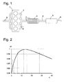
- Fig. 1 shows schematically an engine block 1 of a diesel engine having four cylinders, an exhaust manifold 2 for connecting each cylinder of the engine block to a particulate filter 3, a muffler 5, an exhaust duct 4 extending between the particulate filter 3 and the muffler 5, and an outlet section 6.
- a pressure drop occurs in any of its components, so that the pressure to which is exposed e. g.
- an oxygen sensor 7 adjacent to an inlet of particulate filter 3 may be different from a pressure measured by a pressure sensor 8 in a upstream portion of the exhaust manifold 2, and the pressure drop to which is subject the particulate filter 3 is different from the difference between the pressure detected by sensor 8 and the ambient pressure.
- the mass flow through the exhaust system must be known.
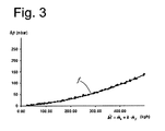
- Fig. 2 is a graph of correlation coefficient R 2 obtained between measured and estimated pressure drops in the exhaust system of Fig. 1 as a function of the weighting coefficient k.
- a correlation coefficient between measured and estimated pressure drops of slightly better than 0.96 is obtained.
- the correlation coefficient becomes better than 0.97.
- the correlation is better than 0.99, and for 12 ⁇ k ⁇ 15 it is nearly perfect at >0.998. It is immediately apparent that any temperature and/or load dependencies of the pressure drop in the exhaust system can be taken account of perfectly by choosing an appropriate value of the weighting coefficient k.
- dots represent measured values
- a curve f gives the estimated relationship between weighted mass flow ⁇ and pressure drop.
- the agreement between estimate and experimental data is practically perfect.
- the curve f of Fig. 3 is a second order polynomial which can be obtained e. g. by least-squares-fitting to the experimental data.
- engine block 1 exhaust manifold 2 particulate filter 3 exhaust duct 4 muffler 5 outlet section 6 oxygen sensor 7 pressure sensor 8 airflow sensor 9
Landscapes
- Engineering & Computer Science (AREA)
- Chemical & Material Sciences (AREA)
- Combustion & Propulsion (AREA)
- Mechanical Engineering (AREA)
- General Engineering & Computer Science (AREA)
- Analytical Chemistry (AREA)
- Chemical Kinetics & Catalysis (AREA)
- Combined Controls Of Internal Combustion Engines (AREA)
- Exhaust Gas After Treatment (AREA)
- Measuring Volume Flow (AREA)
- Processes For Solid Components From Exhaust (AREA)
- Measuring Fluid Pressure (AREA)
Abstract
Description
- The present invention relates to a method for estimating a pressure drop between two sections of an exhaust line of a diesel engine. It is known that the pressure drop between any two sections of a fluid line is mainly a function of the mass flow rate of the fluid circulating in it. In case of an exhaust line, it is not convenient to measure directly the exhaust mass flow, but in most control strategies for diesel engines flow rates of fresh air and of fuel supplied to the engine are known, so that the exhaust gas mass flow can easily be calculated from these. Accordingly, it is suggested e. g. in
EP 1 081 347 B1 - The function f is a polynomial, the coefficients of which are identified from experimental data. This method is rather tedious to implement, since a large quantity of experimental data is necessary to fit the polynomial f in the two variables WDPF, Tb. Further for estimating the pressure pb downstream of the particulate filter, the temperature Tb at the downstream side of the filter has to be known. So either a sensor must be provided for measuring Tb, or a mathematical model must be developed for calculating it.
- The object of the present invention is to provide a method for estimating a pressure drop between two sections of an exhaust line of a diesel engine which is easier and quicker to implement than conventional methods.
- This object is achieved by a method comprising the steps of
- measuring a fresh air flow rate into the engine,
- measuring a fuel flow rate into the engine,
- calculating an exhaust gas flow rate from said fresh air and fuel flow rates, and
- determining an estimated pressure drop as a function of said exhaust gas flow rate,
which is characterized in that the exhaust gas flow rate is calculated as a weighted sum of said fresh air and fuel flow rates, wherein a weighting factor of the fuel flow rate is higher than a weighting factor of the fresh air flow rate. - It appears that using such a weighting factor, temperature dependency of the pressure drop can be taken account of in a very simple and straightforward fashion.
- Experiments have shown that the weighting factor of the fuel flow rate should be at least twice that of the fresh air flow rate, and that it should preferably be in a range between 5 and 30 times that of the fresh air flow rate.
- The function yielding the pressure drop preferably is a polynomial in the exhaust gas flow rate, and it may have the exhaust gas flow rate as its only variable.
- If the method is applied to an exhaust line wherein one of said sections comprises a pressure sensor and the other section comprises a second sensor which gives pressure dependent readings, the method preferably further comprises the steps of calculating a pressure in said other section based on a pressure reading from said pressure sensor and the estimated pressure drop, and of compensating a reading from said second sensor based on the calculated pressure. Such a second sensor can e. g. be an oxygen sensor.
- Alternatively, one of said sections may be a downstream end of the exhaust line. Since the downstream end is necessarily always at ambient pressure, it is possible to calculate the pressure in any other section of the exhaust line without having to use a pressure sensor.
- Further features and advantages of the present invention will become apparent from the subsequent description of embodiments thereof referring to the appended drawings.
- Fig. 1
- is a schematic diagram of an exhaust system of a diesel engine;
- Fig. 2
- is a graph of the correlation coefficient between exhaust flow rate and pressure drop; and
- Fig. 3
- is a graph of measured and estimated pressure drops as a function of the exhaust gas flow rate.
-
Fig. 1 shows schematically anengine block 1 of a diesel engine having four cylinders, anexhaust manifold 2 for connecting each cylinder of the engine block to aparticulate filter 3, amuffler 5, anexhaust duct 4 extending between theparticulate filter 3 and themuffler 5, and anoutlet section 6. When the engine is operating, and exhaust gas is flowing through the exhaust system ofFig. 1 , a pressure drop occurs in any of its components, so that the pressure to which is exposed e. g. anoxygen sensor 7 adjacent to an inlet ofparticulate filter 3 may be different from a pressure measured by a pressure sensor 8 in a upstream portion of theexhaust manifold 2, and the pressure drop to which is subject theparticulate filter 3 is different from the difference between the pressure detected by sensor 8 and the ambient pressure. - In order to estimate a pressure drop between any two points of the exhaust system or between a given point of the exhaust system and the outside environment, the mass flow through the exhaust system must be known. Conventionally, an
airflow sensor 9 is provided in the intake manifold of the engine for detecting the fresh air flow into the cylinders, and the fuel supplied to the cylinders is metered and is thus known, too. It can therefore be concluded that the mass flow rate me of the exhaust gas expelled from theengine block 1 should be the sum ṁe = ṁa + ṁf of fresh air flow rate ṁa and fuel flow rate ṁf. It is found, however, that based on a thus calculated exhaust gas flow rate, a completely reliable prediction of a pressure drop in the exhaust system is not possible. This is not so surprising, because it is known that the pressure drop depends not only on the mass flow rate, but also on the temperature of the flowing gas, and this temperature may vary according to the operating conditions of the engine. Surprisingly, however, it was found that this influence can be taken account of by replacing the above algebraic mass flow by a weighted mass flow M given by
wherein k is a positive constant. -
Fig. 2 is a graph of correlation coefficient R2 obtained between measured and estimated pressure drops in the exhaust system ofFig. 1 as a function of the weighting coefficient k. In this graph, the algebraic mass flow ṁe corresponds to a weighting coefficient k=1. For this weighting coefficient, a correlation coefficient between measured and estimated pressure drops of slightly better than 0.96 is obtained. With a weighting coefficient k=2, the correlation coefficient becomes better than 0.97. In a range of 6 < k < 28, the correlation is better than 0.99, and for 12 < k < 15 it is nearly perfect at >0.998. It is immediately apparent that any temperature and/or load dependencies of the pressure drop in the exhaust system can be taken account of perfectly by choosing an appropriate value of the weighting coefficient k. -
Fig. 3 illustrates the relation Δp=f(Ṁ)between pressure drop Δp and weighted mass flow Ṁ in a practical operating range of the engine. In this graph, dots represent measured values, and a curve f gives the estimated relationship between weighted mass flow Ṁ and pressure drop. The agreement between estimate and experimental data is practically perfect. The curve f ofFig. 3 is a second order polynomial which can be obtained e. g. by least-squares-fitting to the experimental data. - The optimum value of the weighting coefficient k may depend to a certain extent on the characteristics of the engine. However, the optimum weighting coefficient for a given engine may be obtained quite straightforwardly by obtaining experimental data of pressure drop Δp, fresh air flow rate ṁa and fuel flow rate ṁf and carrying out a least-squares fit for polynomial coefficients a2, a1 and weighting factor k in formula

-
engine block 1
exhaust manifold 2
particulate filter 3
exhaustduct 4
muffler 5
outlet section 6
oxygen sensor 7
pressure sensor 8
airflow sensor 9
Claims (6)
- A method for estimating a pressure drop (Δp) between two sections of an exhaust line of a Diesel engine, comprising the steps of- measuring a fresh air flow rate (ṁa ) into the engine,- measuring a fuel flow rate (ṁf ) into the engine,- calculating an exhaust gas flow rate (Ṁ) from said fresh air and fuel flow rates (ṁa ,ṁf ),- determining an estimated pressure drop (Δp)as a function of said exhaust gas flow rate (Ṁ),characterized in that the exhaust gas flow rate (Ṁ) is calculated as a weighted sum of said fresh air and fuel flow rates (ṁa,ṁf ) wherein a weighting factor (k) of the fuel flow rate (ṁf ) is higher than a weighting factor of the fresh air flow rate (ṁa ).
- The method of claim 1, wherein the weighting factor (k) of the fuel flow rate (ṁf ) is at least twice that of the fresh air flow rate (ṁa ).
- The method of claim 1, wherein the weighting factor of the fuel flow rate (ṁf ) is between 5 and 30 times that of the fresh air flow rate (ṁa ).
- The method of any of the preceding claims, wherein the function (f) yielding the pressure drop (Δp ) is a polynomial in the exhaust gas flow rate (Ṁ).
- The method of any of the preceding claims, wherein one of said sections comprises a pressure sensor (8) and the other section comprises a second sensor (7) which gives pressure-dependent readings, further comprising the steps of calculating a pressure in said other section based on a pressure reading from said pressure sensor (8) and said estimated pressure drop, and of compensating a reading from said second sensor (7) based on the calculated pressure.
- The method of any of claims 1 to 4, wherein one of said sections is a downstream end (6) of the exhaust line.
Applications Claiming Priority (1)
| Application Number | Priority Date | Filing Date | Title |
|---|---|---|---|
| IT000385A ITRM20070385A1 (en) | 2007-07-12 | 2007-07-12 | ESTIMATION PROCEDURE OF THE PRESSURE FALL BETWEEN TWO SECTIONS OF THE EXHAUST LINE OF AN INTERNAL COMBUSTION ENGINE. |
Publications (3)
| Publication Number | Publication Date |
|---|---|
| EP2014888A2 true EP2014888A2 (en) | 2009-01-14 |
| EP2014888A3 EP2014888A3 (en) | 2010-03-24 |
| EP2014888B1 EP2014888B1 (en) | 2011-08-03 |
Family
ID=39855752
Family Applications (1)
| Application Number | Title | Priority Date | Filing Date |
|---|---|---|---|
| EP08009370A Not-in-force EP2014888B1 (en) | 2007-07-12 | 2008-05-21 | Method of estimation of the pressure drop between two sections of the exhaust line of an internal combustion engine |
Country Status (5)
| Country | Link |
|---|---|
| US (1) | US20090018784A1 (en) |
| EP (1) | EP2014888B1 (en) |
| CN (1) | CN101344025B (en) |
| AT (1) | ATE519025T1 (en) |
| IT (1) | ITRM20070385A1 (en) |
Cited By (1)
| Publication number | Priority date | Publication date | Assignee | Title |
|---|---|---|---|---|
| US10126205B2 (en) | 2014-08-11 | 2018-11-13 | Isuzu Motors Limited | Sensor |
Families Citing this family (4)
| Publication number | Priority date | Publication date | Assignee | Title |
|---|---|---|---|---|
| US7987672B2 (en) * | 2008-01-22 | 2011-08-02 | GM Global Technology Operations LLC | Turbocharger protection systems and methods |
| US20110160919A1 (en) * | 2009-12-30 | 2011-06-30 | Orr David C | Mobile fluid delivery control system and method |
| US8360343B2 (en) | 2010-04-30 | 2013-01-29 | Caterpillar Inc. | Methods and systems for executing fluid delivery mission |
| CN109736924A (en) * | 2018-12-29 | 2019-05-10 | 成都威特电喷有限责任公司 | A kind of diesel exhaust gas flow statistical system based on DPF post-processing control |
Citations (1)
| Publication number | Priority date | Publication date | Assignee | Title |
|---|---|---|---|---|
| EP1081347B1 (en) | 1999-09-03 | 2003-04-23 | Ford Global Technologies, Inc., A subsidiary of Ford Motor Company | Method to determine the amount of diesel particulate accumulated in a DPF |
Family Cites Families (6)
| Publication number | Priority date | Publication date | Assignee | Title |
|---|---|---|---|---|
| US4986069A (en) * | 1989-08-29 | 1991-01-22 | Donaldson Company, Inc. | Engine exhaust particle trap captured mass sensor |
| CA2154011C (en) * | 1995-07-17 | 1999-06-08 | Gerhard O. Klopp | Exhaust gas recirculation system for a compression ignition engine and a method of controlling exhaust gas recirculation in a compression ignition engine |
| WO1999014476A1 (en) * | 1997-09-17 | 1999-03-25 | Robert Bosch Gmbh | Method and device for determining the gas intake in an internal combustion engine |
| FR2781251B1 (en) * | 1998-07-20 | 2000-09-08 | Renault | METHOD AND DEVICE FOR DETERMINING THE LOAD OF A PARTICLE FILTER |
| DE19949502A1 (en) * | 1999-10-14 | 2001-04-19 | Volkswagen Ag | Method for determining the loading value of a particle filter in internal combustion engines, especially diesel engines |
| DE102004040924B4 (en) * | 2004-08-24 | 2019-04-11 | Robert Bosch Gmbh | Method and device for monitoring pressure sensors in the exhaust gas system |
-
2007
- 2007-07-12 IT IT000385A patent/ITRM20070385A1/en unknown
-
2008
- 2008-05-21 EP EP08009370A patent/EP2014888B1/en not_active Not-in-force
- 2008-05-21 AT AT08009370T patent/ATE519025T1/en not_active IP Right Cessation
- 2008-07-02 CN CN2008101319502A patent/CN101344025B/en not_active Expired - Fee Related
- 2008-07-10 US US12/171,145 patent/US20090018784A1/en not_active Abandoned
Patent Citations (1)
| Publication number | Priority date | Publication date | Assignee | Title |
|---|---|---|---|---|
| EP1081347B1 (en) | 1999-09-03 | 2003-04-23 | Ford Global Technologies, Inc., A subsidiary of Ford Motor Company | Method to determine the amount of diesel particulate accumulated in a DPF |
Cited By (1)
| Publication number | Priority date | Publication date | Assignee | Title |
|---|---|---|---|---|
| US10126205B2 (en) | 2014-08-11 | 2018-11-13 | Isuzu Motors Limited | Sensor |
Also Published As
| Publication number | Publication date |
|---|---|
| CN101344025B (en) | 2012-07-11 |
| US20090018784A1 (en) | 2009-01-15 |
| CN101344025A (en) | 2009-01-14 |
| ATE519025T1 (en) | 2011-08-15 |
| EP2014888B1 (en) | 2011-08-03 |
| EP2014888A3 (en) | 2010-03-24 |
| ITRM20070385A1 (en) | 2009-01-13 |
Similar Documents
| Publication | Publication Date | Title |
|---|---|---|
| EP3633169B1 (en) | Method and apparatus for measuring and controlling the egr rate in a combustion engine | |
| US20110072789A1 (en) | Particulate matter sensor and exhaust gas purification apparatus | |
| US11585258B2 (en) | Method for determining the loading of a soot filter | |
| US20120004863A1 (en) | Method of monitoring soot mass in a particulate filter and monitoring system for same with correction for active regeneration inefficiency | |
| EP1455060B1 (en) | Engine exhaust gas purification device | |
| US8677748B2 (en) | Fresh air flow estimation | |
| EP2010777B1 (en) | Control apparatus and control method for internal combustion engine having centrifugal compressor | |
| EP2014888B1 (en) | Method of estimation of the pressure drop between two sections of the exhaust line of an internal combustion engine | |
| EP1081347B1 (en) | Method to determine the amount of diesel particulate accumulated in a DPF | |
| IT201800002311A1 (en) | METHOD FOR DETERMINING THE QUANTITY OF METALLIC DUST ACCUMULATED IN A PARTICULATE FILTER FOR AN INTERNAL COMBUSTION ENGINE | |
| US20050178207A1 (en) | Method for recognizing the loading of a particle filter | |
| CN101353989A (en) | Adaptive barometric pressure estimation | |
| CN101292081B (en) | Exhaust purification equipment for internal combustion engines | |
| CN101652552B (en) | Method for Determining Particulate Emissions from the Exhaust Stream of an Internal Combustion Engine | |
| JP6436291B2 (en) | Control device for internal combustion engine | |
| CN106795824B (en) | Combustion engine for a motor vehicle with improved abundance control | |
| Fulton et al. | Exhaust manifold temperature observer model | |
| EP3085946A1 (en) | Control device for internal combustion engine | |
| US6697743B2 (en) | Apparatus for measuring intake air flow of internal combustion engine | |
| JP4665843B2 (en) | Abnormality determination device for internal combustion engine | |
| KR20060090663A (en) | Method for determining temperature downstream of inlet of catalytic converter for turbocharged engine | |
| JP5062415B2 (en) | Exhaust gas detection system for exhaust purification means | |
| EP1559891A1 (en) | Turbocharged engine control method having improved smoke control | |
| Cavina et al. | UEGO-based exhaust gas mass flow rate measurement | |
| McKee | Mapping and predicting air flows in gas turbine axial compressors |
Legal Events
| Date | Code | Title | Description |
|---|---|---|---|
| PUAI | Public reference made under article 153(3) epc to a published international application that has entered the european phase |
Free format text: ORIGINAL CODE: 0009012 |
|
| AK | Designated contracting states |
Kind code of ref document: A2 Designated state(s): AT BE BG CH CY CZ DE DK EE ES FI FR GB GR HR HU IE IS IT LI LT LU LV MC MT NL NO PL PT RO SE SI SK TR |
|
| AX | Request for extension of the european patent |
Extension state: AL BA MK RS |
|
| PUAL | Search report despatched |
Free format text: ORIGINAL CODE: 0009013 |
|
| AK | Designated contracting states |
Kind code of ref document: A3 Designated state(s): AT BE BG CH CY CZ DE DK EE ES FI FR GB GR HR HU IE IS IT LI LT LU LV MC MT NL NO PL PT RO SE SI SK TR |
|
| AX | Request for extension of the european patent |
Extension state: AL BA MK RS |
|
| 17P | Request for examination filed |
Effective date: 20100924 |
|
| AKX | Designation fees paid |
Designated state(s): AT BE BG CH CY CZ DE DK EE ES FI FR GB GR HR HU IE IS IT LI LT LU LV MC MT NL NO PL PT RO SE SI SK TR |
|
| 17Q | First examination report despatched |
Effective date: 20101123 |
|
| GRAP | Despatch of communication of intention to grant a patent |
Free format text: ORIGINAL CODE: EPIDOSNIGR1 |
|
| RIC1 | Information provided on ipc code assigned before grant |
Ipc: F01N 9/00 20060101AFI20110328BHEP |
|
| GRAS | Grant fee paid |
Free format text: ORIGINAL CODE: EPIDOSNIGR3 |
|
| GRAA | (expected) grant |
Free format text: ORIGINAL CODE: 0009210 |
|
| RAP1 | Party data changed (applicant data changed or rights of an application transferred) |
Owner name: GM GLOBAL TECHNOLOGY OPERATIONS LLC |
|
| AK | Designated contracting states |
Kind code of ref document: B1 Designated state(s): AT BE BG CH CY CZ DE DK EE ES FI FR GB GR HR HU IE IS IT LI LT LU LV MC MT NL NO PL PT RO SE SI SK TR |
|
| REG | Reference to a national code |
Ref country code: GB Ref legal event code: FG4D |
|
| REG | Reference to a national code |
Ref country code: CH Ref legal event code: EP |
|
| REG | Reference to a national code |
Ref country code: IE Ref legal event code: FG4D |
|
| REG | Reference to a national code |
Ref country code: DE Ref legal event code: R096 Ref document number: 602008008532 Country of ref document: DE Effective date: 20110929 |
|
| REG | Reference to a national code |
Ref country code: NL Ref legal event code: VDEP Effective date: 20110803 |
|
| LTIE | Lt: invalidation of european patent or patent extension |
Effective date: 20110803 |
|
| PG25 | Lapsed in a contracting state [announced via postgrant information from national office to epo] |
Ref country code: IS Free format text: LAPSE BECAUSE OF FAILURE TO SUBMIT A TRANSLATION OF THE DESCRIPTION OR TO PAY THE FEE WITHIN THE PRESCRIBED TIME-LIMIT Effective date: 20111203 Ref country code: NL Free format text: LAPSE BECAUSE OF FAILURE TO SUBMIT A TRANSLATION OF THE DESCRIPTION OR TO PAY THE FEE WITHIN THE PRESCRIBED TIME-LIMIT Effective date: 20110803 Ref country code: PT Free format text: LAPSE BECAUSE OF FAILURE TO SUBMIT A TRANSLATION OF THE DESCRIPTION OR TO PAY THE FEE WITHIN THE PRESCRIBED TIME-LIMIT Effective date: 20111205 Ref country code: HR Free format text: LAPSE BECAUSE OF FAILURE TO SUBMIT A TRANSLATION OF THE DESCRIPTION OR TO PAY THE FEE WITHIN THE PRESCRIBED TIME-LIMIT Effective date: 20110803 Ref country code: FI Free format text: LAPSE BECAUSE OF FAILURE TO SUBMIT A TRANSLATION OF THE DESCRIPTION OR TO PAY THE FEE WITHIN THE PRESCRIBED TIME-LIMIT Effective date: 20110803 Ref country code: SE Free format text: LAPSE BECAUSE OF FAILURE TO SUBMIT A TRANSLATION OF THE DESCRIPTION OR TO PAY THE FEE WITHIN THE PRESCRIBED TIME-LIMIT Effective date: 20110803 Ref country code: NO Free format text: LAPSE BECAUSE OF FAILURE TO SUBMIT A TRANSLATION OF THE DESCRIPTION OR TO PAY THE FEE WITHIN THE PRESCRIBED TIME-LIMIT Effective date: 20111103 Ref country code: LT Free format text: LAPSE BECAUSE OF FAILURE TO SUBMIT A TRANSLATION OF THE DESCRIPTION OR TO PAY THE FEE WITHIN THE PRESCRIBED TIME-LIMIT Effective date: 20110803 |
|
| REG | Reference to a national code |
Ref country code: AT Ref legal event code: MK05 Ref document number: 519025 Country of ref document: AT Kind code of ref document: T Effective date: 20110803 |
|
| PG25 | Lapsed in a contracting state [announced via postgrant information from national office to epo] |
Ref country code: PL Free format text: LAPSE BECAUSE OF FAILURE TO SUBMIT A TRANSLATION OF THE DESCRIPTION OR TO PAY THE FEE WITHIN THE PRESCRIBED TIME-LIMIT Effective date: 20110803 Ref country code: LV Free format text: LAPSE BECAUSE OF FAILURE TO SUBMIT A TRANSLATION OF THE DESCRIPTION OR TO PAY THE FEE WITHIN THE PRESCRIBED TIME-LIMIT Effective date: 20110803 Ref country code: AT Free format text: LAPSE BECAUSE OF FAILURE TO SUBMIT A TRANSLATION OF THE DESCRIPTION OR TO PAY THE FEE WITHIN THE PRESCRIBED TIME-LIMIT Effective date: 20110803 Ref country code: GR Free format text: LAPSE BECAUSE OF FAILURE TO SUBMIT A TRANSLATION OF THE DESCRIPTION OR TO PAY THE FEE WITHIN THE PRESCRIBED TIME-LIMIT Effective date: 20111104 Ref country code: SI Free format text: LAPSE BECAUSE OF FAILURE TO SUBMIT A TRANSLATION OF THE DESCRIPTION OR TO PAY THE FEE WITHIN THE PRESCRIBED TIME-LIMIT Effective date: 20110803 Ref country code: CY Free format text: LAPSE BECAUSE OF FAILURE TO SUBMIT A TRANSLATION OF THE DESCRIPTION OR TO PAY THE FEE WITHIN THE PRESCRIBED TIME-LIMIT Effective date: 20110803 |
|
| PG25 | Lapsed in a contracting state [announced via postgrant information from national office to epo] |
Ref country code: BE Free format text: LAPSE BECAUSE OF FAILURE TO SUBMIT A TRANSLATION OF THE DESCRIPTION OR TO PAY THE FEE WITHIN THE PRESCRIBED TIME-LIMIT Effective date: 20110803 |
|
| PG25 | Lapsed in a contracting state [announced via postgrant information from national office to epo] |
Ref country code: CZ Free format text: LAPSE BECAUSE OF FAILURE TO SUBMIT A TRANSLATION OF THE DESCRIPTION OR TO PAY THE FEE WITHIN THE PRESCRIBED TIME-LIMIT Effective date: 20110803 Ref country code: SK Free format text: LAPSE BECAUSE OF FAILURE TO SUBMIT A TRANSLATION OF THE DESCRIPTION OR TO PAY THE FEE WITHIN THE PRESCRIBED TIME-LIMIT Effective date: 20110803 |
|
| PG25 | Lapsed in a contracting state [announced via postgrant information from national office to epo] |
Ref country code: IT Free format text: LAPSE BECAUSE OF FAILURE TO SUBMIT A TRANSLATION OF THE DESCRIPTION OR TO PAY THE FEE WITHIN THE PRESCRIBED TIME-LIMIT Effective date: 20110803 Ref country code: EE Free format text: LAPSE BECAUSE OF FAILURE TO SUBMIT A TRANSLATION OF THE DESCRIPTION OR TO PAY THE FEE WITHIN THE PRESCRIBED TIME-LIMIT Effective date: 20110803 Ref country code: RO Free format text: LAPSE BECAUSE OF FAILURE TO SUBMIT A TRANSLATION OF THE DESCRIPTION OR TO PAY THE FEE WITHIN THE PRESCRIBED TIME-LIMIT Effective date: 20110803 |
|
| PLBE | No opposition filed within time limit |
Free format text: ORIGINAL CODE: 0009261 |
|
| STAA | Information on the status of an ep patent application or granted ep patent |
Free format text: STATUS: NO OPPOSITION FILED WITHIN TIME LIMIT |
|
| PG25 | Lapsed in a contracting state [announced via postgrant information from national office to epo] |
Ref country code: DK Free format text: LAPSE BECAUSE OF FAILURE TO SUBMIT A TRANSLATION OF THE DESCRIPTION OR TO PAY THE FEE WITHIN THE PRESCRIBED TIME-LIMIT Effective date: 20110803 |
|
| 26N | No opposition filed |
Effective date: 20120504 |
|
| REG | Reference to a national code |
Ref country code: DE Ref legal event code: R097 Ref document number: 602008008532 Country of ref document: DE Effective date: 20120504 |
|
| PG25 | Lapsed in a contracting state [announced via postgrant information from national office to epo] |
Ref country code: MC Free format text: LAPSE BECAUSE OF NON-PAYMENT OF DUE FEES Effective date: 20120531 |
|
| REG | Reference to a national code |
Ref country code: CH Ref legal event code: PL |
|
| PG25 | Lapsed in a contracting state [announced via postgrant information from national office to epo] |
Ref country code: LI Free format text: LAPSE BECAUSE OF NON-PAYMENT OF DUE FEES Effective date: 20120531 Ref country code: CH Free format text: LAPSE BECAUSE OF NON-PAYMENT OF DUE FEES Effective date: 20120531 |
|
| REG | Reference to a national code |
Ref country code: IE Ref legal event code: MM4A |
|
| PG25 | Lapsed in a contracting state [announced via postgrant information from national office to epo] |
Ref country code: IE Free format text: LAPSE BECAUSE OF NON-PAYMENT OF DUE FEES Effective date: 20120521 Ref country code: ES Free format text: LAPSE BECAUSE OF FAILURE TO SUBMIT A TRANSLATION OF THE DESCRIPTION OR TO PAY THE FEE WITHIN THE PRESCRIBED TIME-LIMIT Effective date: 20111114 |
|
| PG25 | Lapsed in a contracting state [announced via postgrant information from national office to epo] |
Ref country code: BG Free format text: LAPSE BECAUSE OF FAILURE TO SUBMIT A TRANSLATION OF THE DESCRIPTION OR TO PAY THE FEE WITHIN THE PRESCRIBED TIME-LIMIT Effective date: 20111103 |
|
| PG25 | Lapsed in a contracting state [announced via postgrant information from national office to epo] |
Ref country code: MT Free format text: LAPSE BECAUSE OF FAILURE TO SUBMIT A TRANSLATION OF THE DESCRIPTION OR TO PAY THE FEE WITHIN THE PRESCRIBED TIME-LIMIT Effective date: 20110803 |
|
| PG25 | Lapsed in a contracting state [announced via postgrant information from national office to epo] |
Ref country code: TR Free format text: LAPSE BECAUSE OF FAILURE TO SUBMIT A TRANSLATION OF THE DESCRIPTION OR TO PAY THE FEE WITHIN THE PRESCRIBED TIME-LIMIT Effective date: 20110803 |
|
| PG25 | Lapsed in a contracting state [announced via postgrant information from national office to epo] |
Ref country code: LU Free format text: LAPSE BECAUSE OF NON-PAYMENT OF DUE FEES Effective date: 20120521 |
|
| PG25 | Lapsed in a contracting state [announced via postgrant information from national office to epo] |
Ref country code: HU Free format text: LAPSE BECAUSE OF FAILURE TO SUBMIT A TRANSLATION OF THE DESCRIPTION OR TO PAY THE FEE WITHIN THE PRESCRIBED TIME-LIMIT Effective date: 20080521 |
|
| REG | Reference to a national code |
Ref country code: FR Ref legal event code: PLFP Year of fee payment: 9 |
|
| REG | Reference to a national code |
Ref country code: FR Ref legal event code: PLFP Year of fee payment: 10 |
|
| PGFP | Annual fee paid to national office [announced via postgrant information from national office to epo] |
Ref country code: FR Payment date: 20170413 Year of fee payment: 10 Ref country code: GB Payment date: 20170517 Year of fee payment: 10 Ref country code: DE Payment date: 20170516 Year of fee payment: 10 |
|
| REG | Reference to a national code |
Ref country code: DE Ref legal event code: R119 Ref document number: 602008008532 Country of ref document: DE |
|
| GBPC | Gb: european patent ceased through non-payment of renewal fee |
Effective date: 20180521 |
|
| PG25 | Lapsed in a contracting state [announced via postgrant information from national office to epo] |
Ref country code: GB Free format text: LAPSE BECAUSE OF NON-PAYMENT OF DUE FEES Effective date: 20180521 Ref country code: FR Free format text: LAPSE BECAUSE OF NON-PAYMENT OF DUE FEES Effective date: 20180531 Ref country code: DE Free format text: LAPSE BECAUSE OF NON-PAYMENT OF DUE FEES Effective date: 20181201 |