EP2014471B1 - Micro patch coating device and method - Google Patents
Micro patch coating device and method Download PDFInfo
- Publication number
- EP2014471B1 EP2014471B1 EP20070013373 EP07013373A EP2014471B1 EP 2014471 B1 EP2014471 B1 EP 2014471B1 EP 20070013373 EP20070013373 EP 20070013373 EP 07013373 A EP07013373 A EP 07013373A EP 2014471 B1 EP2014471 B1 EP 2014471B1
- Authority
- EP
- European Patent Office
- Prior art keywords
- fluid
- coating
- micro
- substrate
- patch
- Prior art date
- Legal status (The legal status is an assumption and is not a legal conclusion. Google has not performed a legal analysis and makes no representation as to the accuracy of the status listed.)
- Active
Links
Images









Classifications
-
- B—PERFORMING OPERATIONS; TRANSPORTING
- B41—PRINTING; LINING MACHINES; TYPEWRITERS; STAMPS
- B41J—TYPEWRITERS; SELECTIVE PRINTING MECHANISMS, i.e. MECHANISMS PRINTING OTHERWISE THAN FROM A FORME; CORRECTION OF TYPOGRAPHICAL ERRORS
- B41J2/00—Typewriters or selective printing mechanisms characterised by the printing or marking process for which they are designed
- B41J2/005—Typewriters or selective printing mechanisms characterised by the printing or marking process for which they are designed characterised by bringing liquid or particles selectively into contact with a printing material
Definitions
- the present invention relates to a coating device and method, and in particular to a micro patch coating device which can be applied in the fabrication of color filters of flat panel liquid crystal displays (LCD) and coloring unit of the fluorescent film in plasma display modules, or in the manufacturing of biomedical products and flexible electronics and cells.
- LCD liquid crystal displays
- Flat panel display has gradually replaced the conventional cathode ray tubes (CRT) display.
- CRT cathode ray tubes
- Flat panel LCD for instance, which takes up the largest market share among all flat panel displays, is composed of backlight source, light polarizer, glass substrate, liquid crystal, thin film transistor (TFT), color filter (CF), etc., while the color filter is the key component determining the color characteristics and contrast of a LCD.
- Color filters in LCD and coloring unit for the fluorescent film in plasma display panel modules are the key components of the structures that convert black and white flat panel display into colorful ones.
- the coating structures of color filter for flat panel LCD for instance, comprises a plurality of pixels of red (R), green (G) and blue (B) colors which are arranged in arrays on glass substrate, while a couple of pixels (normally three) correspond to one color dot on the display.
- RGB red
- G green
- B blue
- white light passes through the trichromatic pixels, it generates three primary colors of light, namely the red, green and blue light, which, by means of gray scale effect generated by the liquid crystal molecules, are further blended and form various colors.
- the technologies for the fabrication of color filters can be classified into three types.
- the first coating type is photolithography method, which is the most frequently used technology currently. In the technology, uniform liquid films are coated to the substrate and defined patterns by photolithography method sequentially. This technology is applied to many methods including dyeing method, pigment dispersing method, electro-deposition, etc.
- Another type of technology is stamping, in which the patterns are respectively decided by stamps and impressed onto the substrate.
- the third type of technology is ink injection, in which miniscule droplets of ink are injected onto a substrate by ink injecting heads, allowing direct formation of micro patch patterns.
- the prerequisite is to coat a liquid film uniformly.
- the most frequently used coating method is spin coating (as disclosed in US Patent 4,451,507 ).
- the method has recently been phased out by other developments, such as extrusion spin coating (as disclosed in US Patent 6,191,053 ) and slot patch coating (as disclosed in US Patent 4,938,994 ). Both inventions aim to improve the material utility rate to allow the formation of uniform liquid film.
- the difference among the various methods, the dyeing method, pigment dispersing method and electro-deposition lies in that the coating liquid film materials have different characteristics and accordingly specific operation procedures are applied.
- the conventional dyeing method processes a dye absorbing layer made from transparent organic photosensitive material by photolithography and etching to form a pattern.
- the dye absorbing layer is immersed in a dyeing solution.
- the display is exposed, dyed, baked and resist dyed to finish.
- the operation procedures are repeated for three cycles to obtain of three layers of color pattern, the red, green and blue colors.
- the method is not only too complicated, but also demands the installation of expensive equipment. Besides, because of the poor resistance of dyes against heat and light, the dyeing method is limited to apply for fabrication of small sized colorful LCD and conventional CRT.
- Known electro-deposition includes generating a patterned and transparent conductive film on a glass substrate and coating the coloring materials thereon by electrophoresis. Similarly, three cycles of the operation procedures are required to produce the patterns in RGB colors. The method also includes photolithography process. Hence, a number of operation parameters are involved, making it difficult to control the yield rate accurately.
- the inclusion of an additional transparent conductive film set forth by this method is the most significant drawback, as it lowers the light permeability and resolution, and hence it limits the layout of the patterns which cannot be too elaborate.
- the conventional coating technology fails to define patterns directly at coating, and it relies, instead, on exposure to remove excessive materials. Thus, it results in low material utility rate throughout the whole process, e.g. less than one third of the material, failing to satisfy the needs for mass production and at low costs.
- Taiwan Patent No. 00535010 A manufacturing method using stamping is disclosed in Taiwan Patent No. 00535010 .
- a stamp with protruded blocks is stained with dyeing materials and the stamp is pressed to define a micro-structure pattern on a transparent insulating substrate which is then baked.
- the procedures are repeated three times to produce patterns with RGB color blocks.
- this method provides limited variation of patterns, making it difficult to change the arrangement of the arrays of pixels at liberty.
- Taiwan Patent No. 00512242 An ink injection method is taught in Taiwan Patent No. 00512242 .
- the ink injection method allows direct control on the positioning of ink injecting head module for defining patterns.
- the procedures of the method are as follows: coating a layer of absorbing film on a glass substrate to secure the absorption of the ink droplets to the glass substrate; next, allowing the ink injecting head module to directly spray the RGB color ink droplets onto the glass substrate to define the patterns required.
- This ink injection method has solved the problem of low material utility rate encountered in the conventional spin coating and photolithography, allowing higher extent of pattern variation than the stamping method.
- the ink injection method basically forms a line or surface pattern by a numerous dots, each droplet must be injected with extremely high accuracy into a block of a few microns or even smaller dimension.
- the traveling paths of droplets are susceptible to air flow disturbance, and it is likely that the ink droplets are injected accidentally to adjacent blocks and results in contamination. Therefore, a high precision machine is required.
- the moving rate of the ink injecting head module is limited to secure precise injection. This can be what holds up the application of the method in industry. Because each of ink injecting heads is allowed to jet only one droplet at one time, the production efficiency is very low. In order to solve this problem, the numbers of the ink injecting heads have to be increased (which inevitably increase the cost).
- a primary object of the present invention is to provide a micro patch coating device to overcome the drawbacks of above-mentioned conventional methods.
- at least one coating fluid and at least one auxiliary fluid are conveyed into a coating die comprising a micro channel structure, generating a two-phase fluid having alternate arrangement of the coating fluid and the auxiliary fluid.
- the coating die is driven to move along a direction in parallel to a substrate and injects the two-phase fluid directly on the substrate at predetermined locations and forms micro patches.
- Another object of the present invention is to provide a slit coating method for generating discontinuous pattern.
- the coating method comprises a fluid generator which alternatively intercepts the supply of a coating fluid and that of an auxiliary fluid. By moving the coating die or the substrate and coating the two-phase fluid on the substrate, micro patches are formed on the substrate.
- the micro patch coating device comprises a coating die with a micro channel structure.
- a coating fluid is supplied through a coating fluid inlet and an auxiliary fluid is supplied through an auxiliary fluid inlet.
- the coating fluid flow is intercepted.
- a segment of predetermined length of the auxiliary fluid is formed at the two-phase fluid output section, and then the auxiliary fluid flow is intercepted.
- a two-phase fluid is formed and flows out of the coating die to the substrate to form micro patches thereon.
- the coating method in the present invention overcomes the low material utility rate problem happened in spin coating and photolithography, and is applicable in coating larger dimension display panels.
- the present invention also solves the problems of low yield rate and low production efficiency in ink injection method, and it allows high degree of variation of the pattern which cannot be achieved by stamping.
- the method of the present invention lowers the manufacturing costs, improves the production efficiency, and is capable to be used for producing larger dimension display panels and sophisticated micro patch patterns for matching the future development.
- the present invention provides higher material utility rate than that of photolithography that requires repeated exposure procedures.
- the present invention saves the processing time.
- coating patterns are formed by varying the output ratio of the coating and auxiliary fluid and the relative movements between the coating die and the substrate. Besides, by directly coating the two-phase fluid to the substrate, the pattern is easily changed than that produced by stamping. Meanwhile, the method does not require of high precision injection as that as required in conventional ink injecting and enables higher yield rate in production.
- FIG. 1 shows a schematic view of a micro patch coating device 100 constructed in accordance with a first embodiment of the present invention.
- the micro patch coating device 100 comprises a micro channel 12, a driving mechanism 13, a supporting member 14, a connector 15, and a fluid driving mechanism 16.
- the micro channel 12 is supported by the supporting member 14 coupled to the driving mechanism 13.
- the supporting member 14 is driven to displace along a horizontal direction I back and forth by the driving mechanism 13.
- the micro channel 12 may be a capillary tube.
- the micro channel 12 has an inlet 121 and an outlet 122.
- the outlet 122 of the micro channel 12 is kept at a predetermined distance from the top surface of a substrate 6.
- the inlet 121 of the micro channel 12 is connected to the fluid driving mechanism 16 composed of a syringe 161, a plunger 162, and a pump 163.
- the connector 15 is connected between the inlet 121 of the micro channel 12 and the syringe 161.
- the syringe 161 comprises a plunger 162 which is connected to the pump 163.
- the pump 163 is controlled by a control device (not shown) to push the plunger 162 forward or pull the plunger 162 backward along a direction II parallel to the lengthwise direction of the syringe 161.
- a control device not shown
- the pump 163 pushes the plunger 162 forward, the two-phase fluid 11 contained in the micro channel 12 is driven to flow out to the outlet 122 of the micro channel 12.
- the driving mechanism 13 drives the micro channel 12 via the supporting member 14 to displace along the horizontal direction I in parallel to the surface of the substrate 6.
- the two-phase fluid 11 contained in the micro channel 12 is composed of a coating fluid flow alternatively intercepted by a plurality of auxiliary fluid flow sections. That is, the two-phase fluid 11 is composed of a number of coating fluids 2a and a number of auxiliary fluids 3.
- Each of the coating fluids 2a contains a specific pigment, e.g. blue, green or red color pigment, while each of the auxiliary fluids 3 comprises a liquid or a gas immiscible with the coating fluid 2a.
- the two-phase fluid 11 is formed of alternating segments including a number of segment 2a' of a predetermined length of the coating fluid 2a and a number of segment 3' of a predetermined length of the auxiliary fluid 3.
- the two-phase fluid 11 After flowing out of the outlet 122, the two-phase fluid 11 is coated at predetermined locations of the substrate 6 and thereby a micro-patch pattern comprising a number of micro patches 7a is formed on the substrate 6.
- micro patches 7a are directly formed on the substrate 6.
- the substrate 6 could be heated to vaporize the auxiliary fluid 3 by baking, leaving the coating fluid 2a to form the micro patches 7a.
- the flowing velocity of the two-phase fluid 11 is determined by the pumping rate of the pump 163 which is controlled through the control device.
- FIG 4 is a schematic view showing a preferred embodiment of two-phase fluid generating device of the present invention.
- a coating fluid supply tank 18 contains the coating fluid 2a therein and supplies the coating fluid 2a to the micro patch coating device 100.
- a through hole 181 is formed at a predetermined position that is below the free surface of the coating fluid 2a in the coating fluid supply tank 18.
- the coating fluid 2a has a surface tension at the through hole 181 that prevents the leakage of the coating fluid 2a from the coating fluid supply tank 18, even though no stopper or sealing is provided at the through hole 181.
- the driving mechanism 13 drives the micro channel 12 to displace along the horizontal direction I, and the micro channel 12 penetrates through the through hole 181 to the coating fluid supply tank 18, as shown in Figure 5 .
- the pump 163 works to pull the plunger 162 to displace backward, and a suction force is generated that causes the coating fluid 2a in the coating fluid supply tank 18 to be drawn into the micro channel 12, forming a segment 2a' of a predetermined length of the coating fluid 2a in the micro channel 12.
- the driving mechanism 13 moves horizontally to withdraw the micro channel 12 out of the coating fluid supply tank 18, while the pump 163 keeps working and accordingly, air is drawn into the micro channel 12, forming a segment 3' of a predetermined length of air which acts as the auxiliary fluid 3. Thereby, a two-phase fluid 11 is formed.
- Figures 7 and 8 show the formation of the two-phase fluid in the micro channel.
- the pump 163 keeps working and the driving mechanism 13 keeps displacing back and forth to repeatedly suck the coating fluid 2a, and then pull the micro channel 12 out of the through hole 181 to draw in air or a specific gas, i.e. the auxiliary fluid 3.
- the micro channel 12 is filled with alternating segments of the coating fluid 2a and the auxiliary fluid 3.
- the two-phase fluid 11 is generated in the micro channel 12.
- the retention time of the micro channel 12 at the coating fluid supply tank 18 and that of the micro channel 12 in the air are regulated to control the length of the segments of the coating fluid 2a and the auxiliary fluid 3.
- the auxiliary fluid is a gas.
- the auxiliary fluid 3 may comprise a liquid immiscible with the coating fluid 2a.
- An auxiliary fluid supply tank (not shown) is provided for supplying the auxiliary fluid.
- the two-phase fluid generating device in Fig. 4 could also be turned 90 degrees counterclockwise, locating above the coating fluid supply tank 18, and drive the micro channel 12 to displace up and down, such that the outlet 122 of the micro channel 12 is below or above the free surface of the coating fluid 2a, and generate the two-phase fluid 11 through the same process mentioned above.
- FIG. 9 is a schematic view showing a micro patch coating device 200 constructed in accordance with a second embodiment of the present invention.
- the second embodiment is similar to the first embodiment and same reference numbers are used for identical components.
- the difference between the second embodiment and the first embodiment is that the micro patch coating device 200 comprises a plurality of micro channels 12a, 12b, 12c arranged in a line and supported by the supporting member 14.
- the pumping of the pump 163 simultaneously drives the two-phase fluid 11 to flow downward from the micro channels 12a, 12b, 12c onto the substrate 6, respectively forming parallel micro patches 7a, 7b, 7c on the substrate 6 at the same time.
- the micro patch coating device 300 comprises a coating die 2 provided with a plurality of coating fluid inlets 21a, 21b, 21c and an auxiliary fluid inlet 22 arranged at specific positions.
- the coating fluid inlets 21a, 21b, 21c are used for respectively supplying coating fluids 2a, 2b, 2c into the coating die 2.
- Each of the coating fluids 2a, 2b, 2c contains a specific pigment, e.g. blue, green or red color pigment, which is different from each other and has specific composition.
- the auxiliary fluid inlet 22 is used for supplying an auxiliary fluid 3 to the coating die 2.
- the auxiliary fluid 3 may comprise a single fluid or a number of different fluids, based on the types of the coating fluids.
- the coating die 2 is provided with a micro channel structure 4 arranged at an interior of the coating die 2.
- the bottom of the coating die 2 is formed with fluid outlets 24.
- the coating fluid inlets 21a, 21b, 21c and the auxiliary fluid inlet 22 are connected to the micro channel structure 4, respectively.
- the micro channel structure 4 comprises a plurality of coating fluid buffering sections 211, 212, 213, a plurality of coating fluid passages 21a', 21b', 21c', a plurality of auxiliary fluid passages 22a, 22b, 22c and a plurality of two-phase fluid output sections 23a, 23b, 23c.
- Each of the coating fluid buffering sections 211, 212, 213 is connected to a coating fluid inlet 21a, 21b, 21c.
- the coating fluid buffering sections 211, 212 and 213 are arranged between the coating fluid inlets 21a, 21b, 21c and the coating fluid passages 21a', 21b', 21c'.
- the coating fluids 2a, 2b, 2c are respectively supplied from the coating fluid inlets 21a, 21b, 21c through the coating fluid buffering sections 211, 212, 213 to the coating fluid passages 21a', 21b', 21c'.
- the auxiliary fluid passages 22a, 22b, 22c are connected to the auxiliary fluid inlet 22.
- the size of the coating fluid passage 21a', 21b', 21c' is smaller than that of the coating fluid buffering sections 211, 212, 213 and that of the coating fluid inlets 21a, 21b, 21c.
- a two-phase fluid generator 5a, 5b, 5c is arranged at a junction between the coating fluid passage 21a', 21b', 21c' and the corresponding auxiliary fluid passage 22a, 22b, 22c.
- Each of the two-phase fluid output sections 23a, 23b, 23c comprises a two-phase fluid inlet 231, 232, 233 at one end and a two-phase fluid outlet 24a, 24b, 24c at the other end.
- the two-phase fluid inlets 231, 232, 233 are respectively connected to the two-phase fluid generators 5a, 5b, 5c for conveying the two-phase fluids 11 generated by the two-phase fluid generators 5a, 5b, 5c.
- the two-phase fluid outlets 24a, 24b, 24c are arranged at the bottom of the coating die 2 and kept at a predetermined distance from the surface of the substrate 6, such that the two-phase fluids 11 flow from the two-phase fluid output sections 23a, 23b, 23c out through the fluid outlets 24 of the coating die 2.
- the auxiliary fluid 3 may comprise a liquid or a gas immiscible with the coating fluids 2a, 2b, 2c.
- the two-phase fluid 11 After flowing out of the fluid outlet 24 of the coating die 2, the two-phase fluid 11 are coated at predetermined locations of the substrate 6 by the movement of the coating die 2 and the substrate 6 along a parallel direction relative to each other.
- a gas is used as the auxiliary fluid, micro patches 7a, 7b, 7c are directly formed on the substrate.
- the substrate 6 could be heated to vaporize the auxiliary fluid 3 by baking, leaving the coating fluid 2a, 2b, 2c to form the micro patches 7a, 7b, 7c.
- FIG. 13 is a schematic view showing the generation of the two-phase fluid by the two-phase flow generator of the micro patch coating device.
- the two-phase fluid generator 5a is arranged at the junction between the coating fluid passage 21a' and the auxiliary fluid passage 22a.
- the two-phase fluid generator 5a comprises an interceptor 5a1.
- the interceptor 5a1 may comprise a valve or it can be a valveless type which is capable to achieve the same functions.
- the coating fluids 2a are delivered through the coating fluid inlet 21 a to the coating fluid buffering section 211 and then to the coating fluid passage 21 a' .
- the auxiliary fluid 3 is delivered from the auxiliary fluid inlet 22 to the auxiliary fluid passage 22a.
- the interceptor 5a1 intercepts the flowing of the coating fluid 2a.
- the intercepted 5a1 allows the auxiliary fluid 3 to flow from the auxiliary fluid passage 22a.
- the interceptor 5a1 intercepts the flowing of the coating fluid 2a.
- the interception actions of the interceptor 5a1 to the coating fluid flow and to the auxiliary fluid flow are proceeded alternatively, forming a two-phase fluid 11 in the two-phase fluid output sections 23a.
- the auxiliary fluid 3 remains immiscible with the coating fluid 2a.
- the two-phase fluid generators are arranged in the micro channel structure 4 inside the coating die 2, forming the two-phase fluid.
- the two-phase fluid generators may be arranged at an exterior of the coating die 2 for forming the two-phase fluid just as well.
- the coating die 2 of the micro patch coating device 300 is located at a predetermined distance above the substrate 6.
- the coating die 2 is driven by a driving mechanism 21 to move back and forth along a horizontal direction I which is parallel to the substrate 6.
- the driving mechanism 21 may comprise a platform conveying device with adjustable speed that allows the regulation of the displacement velocity of the coating die 2.
- Figure 15 is a schematic view showing a movement of the substrate driven by a panel driving mechanism of the micro patch coating device.
- the substrate 6 is located at a predetermined distance below the coating die 2 of the coating device 300.
- the substrate 6 is driven by a panel driving mechanism 6a to move back and forth along a horizontal direction I which is parallel to the coating die 2.
- the panel driving mechanism 6a may comprise a platform conveying device with adjustable speed that allows the regulation of the displacement velocity of the substrate 6.
- both the driving mechanism 21 and the panel driving mechanism 6a may be used at the same time.
- the driving mechanism 21 drives the coating die 2 to move and the panel driving mechanism 6a drives the substrate 6 to move simultaneously along a horizontal direction I to allow parallel and opposite movements. In this way, the coating procedure is speeded up for improving the production efficiency.
- the auxiliary fluid 3 is a gas
- either the coating die 2 or the substrate 6 may be driven to move both in a direction perpendicular to the surface of the substrate 6 of Figure 14 and in a horizontal direction, so as to generate different arrangements of arrays of pixels.
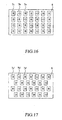
- Figure 16 is a schematic view showing a coating pattern formed on the substrate and Figure 17 is a schematic view showing another coating pattern formed on the substrate.
- the two-phase fluids 11 flow out of the fluid outlet 24 of the coating die 2
- the two-phase fluids 11 are coated at predetermined locations on the substrate 6 by means of the parallel and opposite movements of the coating die 2 and the substrate 6, and form a plurality of micro patches 7a, 7b, 7c.
- the coating fluids 2a, 2b and 2c contains a specific pigment, e.g. blue, green or red color pigment, which is different from each other and has specific composition
- the micro patches 7a, 7b, 7c are formed with the blue, green and red color in a sequence, forming pixels in the form of rectangular matrix.
- either the coating die 2 and the substrate 6 can also be arranged to move in a direction perpendicular to the surface of the substrate 6 of Figure 14 , in order to generate different arrangements of arrays of pixels, as shown in Figure 17 .
- Figure 18 is a flow chart for performing a micro patch coating method in accordance with the present invention.
- a coating die is prepared in step 101.
- the coating die comprises a micro channel structure with at least one coating fluid inlet, at least one auxiliary inlet, at least one two-phase fluid output section and at least one fluid outlet.
- a coating fluid is supplied to the micro channel structure of the coating die from the coating fluid inlet at step 102.
- An auxiliary fluid is supplied to the auxiliary fluid inlet of the micro channel structure at step 103.
- Step 104 The flowing of the coating fluids and the flowing of auxiliary fluid are alternatively intercepted by a two-phase fluid generator (Step 104), generating a two-phase fluid comprising a segment of coating fluid of a predetermined length and a segment of auxiliary fluid of a predetermined length.
- step 105 the two-phase fluid are conveyed to the two-phase fluid output section, and then flows through the two-phase fluid outlet of the fluid output section to the fluid outlet of the coating die at step 106.
- the coating die and the substrate are allowed to move in parallel and opposite direction, allowing the two-phase fluids to flow out of the coating die and coat at predetermined locations on the substrate, defining micro patches directly at step 107a in the case that the auxiliary fluid is a gas.
- the substrate is heated to vaporize the auxiliary fluid by baking, leaving the coating fluid to define micro patches at step 107b.
- Figure 19 is a schematic view showing a micro channel structure of a coating die of a fourth embodiment of the present invention.
- the fourth embodiment is similar to the third embodiment and same reference numbers are used for identical components.
- the difference between the fourth embodiment and the third embodiment is that the auxiliary fluid inlet 22 is arranged below the coating fluid inlets 21a, 21b, 21c.
- the auxiliary fluid passages 22a, 22b, 22c are arranged below the coating fluid passages 21a', 21b', 21c'.
- the coating fluid 2a flows from the coating fluid inlet 21a, through the coating fluid buffering section 211 and the coating fluid passage 21a' to the two-phase fluid generator 5a.
- the auxiliary fluid 3 flow from the auxiliary fluid inlet 22 and the auxiliary fluid passage 22a to the two-phase fluid generator 5a.
- the two-phase fluid generator 5a allows the coating fluid 2a and auxiliary fluid 3 to alternatively flow and intercepted.
- two-phase fluid 11 is formed in the two-phase fluid output section 23a.
- the two-phase fluid 11 flows through the two-phase fluid outlet 24a of the coating die 2.
Landscapes
- Coating Apparatus (AREA)
Description
- The present invention relates to a coating device and method, and in particular to a micro patch coating device which can be applied in the fabrication of color filters of flat panel liquid crystal displays (LCD) and coloring unit of the fluorescent film in plasma display modules, or in the manufacturing of biomedical products and flexible electronics and cells.
- With the development of information technology, flat panel display has gradually replaced the conventional cathode ray tubes (CRT) display. Flat panel LCD, for instance, which takes up the largest market share among all flat panel displays, is composed of backlight source, light polarizer, glass substrate, liquid crystal, thin film transistor (TFT), color filter (CF), etc., while the color filter is the key component determining the color characteristics and contrast of a LCD.
- Color filters in LCD and coloring unit for the fluorescent film in plasma display panel modules are the key components of the structures that convert black and white flat panel display into colorful ones. The coating structures of color filter for flat panel LCD, for instance, comprises a plurality of pixels of red (R), green (G) and blue (B) colors which are arranged in arrays on glass substrate, while a couple of pixels (normally three) correspond to one color dot on the display. When white light passes through the trichromatic pixels, it generates three primary colors of light, namely the red, green and blue light, which, by means of gray scale effect generated by the liquid crystal molecules, are further blended and form various colors.
- The technologies for the fabrication of color filters can be classified into three types. The first coating type is photolithography method, which is the most frequently used technology currently. In the technology, uniform liquid films are coated to the substrate and defined patterns by photolithography method sequentially. This technology is applied to many methods including dyeing method, pigment dispersing method, electro-deposition, etc. Another type of technology is stamping, in which the patterns are respectively decided by stamps and impressed onto the substrate. The third type of technology is ink injection, in which miniscule droplets of ink are injected onto a substrate by ink injecting heads, allowing direct formation of micro patch patterns.
- Referring to photolithography technology mentioned above, the prerequisite is to coat a liquid film uniformly. Currently, the most frequently used coating method is spin coating (as disclosed in
US Patent 4,451,507 ). However, due to low material utility rate, the method has recently been phased out by other developments, such as extrusion spin coating (as disclosed inUS Patent 6,191,053 ) and slot patch coating (as disclosed inUS Patent 4,938,994 ). Both inventions aim to improve the material utility rate to allow the formation of uniform liquid film. The difference among the various methods, the dyeing method, pigment dispersing method and electro-deposition, lies in that the coating liquid film materials have different characteristics and accordingly specific operation procedures are applied. - The conventional dyeing method (as disclosed in
US Patent 4,744,635 ) processes a dye absorbing layer made from transparent organic photosensitive material by photolithography and etching to form a pattern. The dye absorbing layer is immersed in a dyeing solution. Then, the display is exposed, dyed, baked and resist dyed to finish. The operation procedures are repeated for three cycles to obtain of three layers of color pattern, the red, green and blue colors. The method is not only too complicated, but also demands the installation of expensive equipment. Besides, because of the poor resistance of dyes against heat and light, the dyeing method is limited to apply for fabrication of small sized colorful LCD and conventional CRT. - Conventional pigment dispersing method (as disclosed in
US Patents 5,085,973 and4,786,148 ) is the most popular method used in manufacturing color filters currently. Photosensitive and thermosetting pigments are used. The procedures comprise coating coloring material to the mask on the glass substrate, and exposure imaging, baking, etc. to produce monochromatic micro-imaged color patch. Three cycles of operation procedures are required to produce trichromatic RGB pixels. The pigment dispersing method is complicated and requires expensive equipment and the operation is time-consuming, and it has low utility rate of coloring material and limited variation in pixel pattern, and therefore this method is not potential to meet the future demands for larger size and lower price display panel. - Known electro-deposition (as disclosed in
US Patent 4,522,691 ) includes generating a patterned and transparent conductive film on a glass substrate and coating the coloring materials thereon by electrophoresis. Similarly, three cycles of the operation procedures are required to produce the patterns in RGB colors. The method also includes photolithography process. Hence, a number of operation parameters are involved, making it difficult to control the yield rate accurately. The inclusion of an additional transparent conductive film set forth by this method is the most significant drawback, as it lowers the light permeability and resolution, and hence it limits the layout of the patterns which cannot be too elaborate. - To conclude, the conventional coating technology fails to define patterns directly at coating, and it relies, instead, on exposure to remove excessive materials. Thus, it results in low material utility rate throughout the whole process, e.g. less than one third of the material, failing to satisfy the needs for mass production and at low costs.
- A manufacturing method using stamping is disclosed in Taiwan Patent No.
00535010 - An ink injection method is taught in Taiwan Patent No.
00512242 - However, since the ink injection method basically forms a line or surface pattern by a numerous dots, each droplet must be injected with extremely high accuracy into a block of a few microns or even smaller dimension. Besides, the traveling paths of droplets are susceptible to air flow disturbance, and it is likely that the ink droplets are injected accidentally to adjacent blocks and results in contamination. Therefore, a high precision machine is required. Also, the moving rate of the ink injecting head module is limited to secure precise injection. This can be what holds up the application of the method in industry. Because each of ink injecting heads is allowed to jet only one droplet at one time, the production efficiency is very low. In order to solve this problem, the numbers of the ink injecting heads have to be increased (which inevitably increase the cost). Besides, when ink injections are taking place in parallel movements, all ink injecting heads have to be in good condition without any clogging or abnormal situation. When the ink injection method is applied in large sized display panels, an enlarged dimension of machine is used. It should be careful to maintain good machine mobility and coating uniformity. These problems are yet to be solved in the future when large dimension TV displays will become the major products.
- Thus, it is desired to develop a coating method that is simple in operation, has good yield rate and is economical for application.
-
US-A-2002/015069 discloses the preamble of claim 1. - A primary object of the present invention is to provide a micro patch coating device to overcome the drawbacks of above-mentioned conventional methods. In the present invention, at least one coating fluid and at least one auxiliary fluid are conveyed into a coating die comprising a micro channel structure, generating a two-phase fluid having alternate arrangement of the coating fluid and the auxiliary fluid. The coating die is driven to move along a direction in parallel to a substrate and injects the two-phase fluid directly on the substrate at predetermined locations and forms micro patches.
- Another object of the present invention is to provide a slit coating method for generating discontinuous pattern. The coating method comprises a fluid generator which alternatively intercepts the supply of a coating fluid and that of an auxiliary fluid. By moving the coating die or the substrate and coating the two-phase fluid on the substrate, micro patches are formed on the substrate.
- To fulfill the above objects, the present invention provides a device according to claims 9 to 17 and a method for micro patch coating according to claims 1 to 8. The micro patch coating device comprises a coating die with a micro channel structure. A coating fluid is supplied through a coating fluid inlet and an auxiliary fluid is supplied through an auxiliary fluid inlet. After a segment of a predetermined length of the coating fluid is formed at a two-phase fluid output section, the coating fluid flow is intercepted. In turn, a segment of predetermined length of the auxiliary fluid is formed at the two-phase fluid output section, and then the auxiliary fluid flow is intercepted. A two-phase fluid is formed and flows out of the coating die to the substrate to form micro patches thereon.
- The coating method in the present invention overcomes the low material utility rate problem happened in spin coating and photolithography, and is applicable in coating larger dimension display panels. The present invention also solves the problems of low yield rate and low production efficiency in ink injection method, and it allows high degree of variation of the pattern which cannot be achieved by stamping. The method of the present invention lowers the manufacturing costs, improves the production efficiency, and is capable to be used for producing larger dimension display panels and sophisticated micro patch patterns for matching the future development.
- Furthermore, the present invention provides higher material utility rate than that of photolithography that requires repeated exposure procedures. The present invention saves the processing time. In the coating method of the present invention, coating patterns are formed by varying the output ratio of the coating and auxiliary fluid and the relative movements between the coating die and the substrate. Besides, by directly coating the two-phase fluid to the substrate, the pattern is easily changed than that produced by stamping. Meanwhile, the method does not require of high precision injection as that as required in conventional ink injecting and enables higher yield rate in production.
- The present invention will be apparent to those skilled in the art by reading the following description of embodiment thereof, with reference to the attached drawings, in which:
-
Figure 1 is a perspective view of a micro patch coating device constructed in accordance with a first embodiment of the present invention; -
Figure 2 is a schematic view showing the coating of a two-phase fluid onto a substrate; -
Figure 3 is a schematic view showing the formation of a micro patch on the substrate; -
Figure 4 is a schematic view showing the supply of a coating fluid from a coating fluid supply tank to a micro channel of the micro patch coating device ofFigure 1 ; -
Figure 5 is a cross-sectional view showing the micro channel is driven to connect a coating fluid supply tank and a coating fluid segment is drawn into the micro channel; -
Figure 6 is a cross-sectional view showing an auxiliary fluid segment is drawn into the micro channel; -
Figure 7 is a cross-sectional view showing that the coating fluid is alternatively intercepted by a plurality of auxiliary fluid sections; -
Figure 8 is a cross-sectional view showing that a two-phase fluid is generated in the micro channel; -
Figure 9 is a perspective view of a micro patch coating device constructed in accordance with a second embodiment of the present invention; -
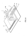
Figure 10 is a perspective view of a micro patch coating device constructed in accordance with a third embodiment of the present invention; -
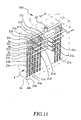
Figure 11 is a schematic view showing a micro channel structure of a coating die of the micro patch coating device ofFigure 10 ; -
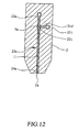
Figure 12 is a cross-sectional view taken along line 12-12 ofFigure 11 ; -
Figure 13 is a schematic view showing the generation of a two-phase fluid by a flow generator of the micro patch coating device ofFigure 10 ; -
Figure 14 is a schematic view showing a movement of the coating die driven by a driving mechanism of the micro patch coating device ofFigure 10 ; -
Figure 15 is a schematic view showing a movement of the substrate driven by a panel driving mechanism of the micro patch coating device ofFigure 10 ; -
Figure 16 is a schematic view showing a coating pattern formed on the substrate by the micro patch coating device ofFigure 10 ; -
Figure 17 is a schematic view showing another coating pattern formed on the substrate by the micro patch coating device ofFigure 10 ; -
Figure 18 is a flow chart for performing a micro patch coating method in accordance with the present invention; -
Figure 19 is a schematic view showing a micro channel structure of a coating die of a fourth embodiment of a micro patch coating device constructed in accordance with the present invention; and -
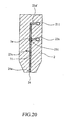
Figure 20 is a cross-sectional view taken along line 20-20 ofFigure 19 . - With reference to the drawings and in particular to
Figure 1 , it shows a schematic view of a micropatch coating device 100 constructed in accordance with a first embodiment of the present invention. The micropatch coating device 100 comprises amicro channel 12, adriving mechanism 13, a supportingmember 14, aconnector 15, and afluid driving mechanism 16. - The
micro channel 12 is supported by the supportingmember 14 coupled to thedriving mechanism 13. The supportingmember 14 is driven to displace along a horizontal direction I back and forth by thedriving mechanism 13. In this embodiment, themicro channel 12 may be a capillary tube. - The
micro channel 12 has aninlet 121 and anoutlet 122. Theoutlet 122 of themicro channel 12 is kept at a predetermined distance from the top surface of asubstrate 6. Theinlet 121 of themicro channel 12 is connected to thefluid driving mechanism 16 composed of asyringe 161, aplunger 162, and apump 163. Theconnector 15 is connected between theinlet 121 of themicro channel 12 and thesyringe 161. - The
syringe 161 comprises aplunger 162 which is connected to thepump 163. Thepump 163 is controlled by a control device (not shown) to push theplunger 162 forward or pull theplunger 162 backward along a direction II parallel to the lengthwise direction of thesyringe 161. When thepump 163 pushes theplunger 162 forward, the two-phase fluid 11 contained in themicro channel 12 is driven to flow out to theoutlet 122 of themicro channel 12. - Meanwhile, the
driving mechanism 13 drives themicro channel 12 via the supportingmember 14 to displace along the horizontal direction I in parallel to the surface of thesubstrate 6. - Please refer to
Figures 2 and 3 , which show the coating of the two-phase fluid onto thesubstrate 6 to form a predetermined micro-patch pattern thereon. The two-phase fluid 11 contained in themicro channel 12 is composed of a coating fluid flow alternatively intercepted by a plurality of auxiliary fluid flow sections. That is, the two-phase fluid 11 is composed of a number ofcoating fluids 2a and a number ofauxiliary fluids 3. Each of thecoating fluids 2a contains a specific pigment, e.g. blue, green or red color pigment, while each of theauxiliary fluids 3 comprises a liquid or a gas immiscible with thecoating fluid 2a. As shown inFigure 3 , the two-phase fluid 11 is formed of alternating segments including a number ofsegment 2a' of a predetermined length of thecoating fluid 2a and a number of segment 3' of a predetermined length of theauxiliary fluid 3. - As it can be seen from the drawings, when the
driving mechanism 13 moves themicro channel 12 to displace horizontally and thefluid driving mechanism 16 pushes the two-phase fluid 11 in themicro channel 12, the two-phase fluid 11 flows out from theoutlet 122 of themicro channel 12, thereby forming a fluid film 7' on thesubstrate 6. - After flowing out of the
outlet 122, the two-phase fluid 11 is coated at predetermined locations of thesubstrate 6 and thereby a micro-patch pattern comprising a number ofmicro patches 7a is formed on thesubstrate 6. - In the case a gas is used as the
auxiliary fluid 3,micro patches 7a are directly formed on thesubstrate 6. In the case a liquid that is immiscible with thecoating fluid 2a is used as theauxiliary fluid 3, thesubstrate 6 could be heated to vaporize theauxiliary fluid 3 by baking, leaving thecoating fluid 2a to form themicro patches 7a. The flowing velocity of the two-phase fluid 11 is determined by the pumping rate of thepump 163 which is controlled through the control device. -
Figure 4 is a schematic view showing a preferred embodiment of two-phase fluid generating device of the present invention. A coatingfluid supply tank 18 contains thecoating fluid 2a therein and supplies thecoating fluid 2a to the micropatch coating device 100. At a side of the coatingfluid supply tank 18, a throughhole 181 is formed at a predetermined position that is below the free surface of thecoating fluid 2a in the coatingfluid supply tank 18. - The
coating fluid 2a has a surface tension at the throughhole 181 that prevents the leakage of thecoating fluid 2a from the coatingfluid supply tank 18, even though no stopper or sealing is provided at the throughhole 181. - For obtaining the two-
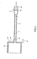
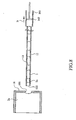
phase fluid 11, thedriving mechanism 13 drives themicro channel 12 to displace along the horizontal direction I, and themicro channel 12 penetrates through the throughhole 181 to the coatingfluid supply tank 18, as shown inFigure 5 . Then thepump 163 works to pull theplunger 162 to displace backward, and a suction force is generated that causes thecoating fluid 2a in the coatingfluid supply tank 18 to be drawn into themicro channel 12, forming asegment 2a' of a predetermined length of thecoating fluid 2a in themicro channel 12. - Please refer to
Figure 6 . Thedriving mechanism 13 moves horizontally to withdraw themicro channel 12 out of the coatingfluid supply tank 18, while thepump 163 keeps working and accordingly, air is drawn into themicro channel 12, forming a segment 3' of a predetermined length of air which acts as theauxiliary fluid 3. Thereby, a two-phase fluid 11 is formed. -
Figures 7 and8 show the formation of the two-phase fluid in the micro channel. Under the control of the control device, thepump 163 keeps working and thedriving mechanism 13 keeps displacing back and forth to repeatedly suck thecoating fluid 2a, and then pull themicro channel 12 out of the throughhole 181 to draw in air or a specific gas, i.e. theauxiliary fluid 3. As a result, themicro channel 12 is filled with alternating segments of thecoating fluid 2a and theauxiliary fluid 3. In other words, the two-phase fluid 11 is generated in themicro channel 12. In application, the retention time of themicro channel 12 at the coatingfluid supply tank 18 and that of themicro channel 12 in the air are regulated to control the length of the segments of thecoating fluid 2a and theauxiliary fluid 3. - In the first embodiment, the auxiliary fluid is a gas. In application, the
auxiliary fluid 3 may comprise a liquid immiscible with thecoating fluid 2a. An auxiliary fluid supply tank (not shown) is provided for supplying the auxiliary fluid. - The two-phase fluid generating device in
Fig. 4 could also be turned 90 degrees counterclockwise, locating above the coatingfluid supply tank 18, and drive themicro channel 12 to displace up and down, such that theoutlet 122 of themicro channel 12 is below or above the free surface of thecoating fluid 2a, and generate the two-phase fluid 11 through the same process mentioned above. - The first embodiment of the micro patch coating device described above is provided with only one micro channel therein. In application, a number of micro channels may be installed in the micro patch coating device for forming a number of parallel micro patches spaced from each other with a predetermined distance on the substrate at the same time. For example,
Figure 9 is a schematic view showing a micropatch coating device 200 constructed in accordance with a second embodiment of the present invention. The second embodiment is similar to the first embodiment and same reference numbers are used for identical components. The difference between the second embodiment and the first embodiment is that the micropatch coating device 200 comprises a plurality ofmicro channels 12a, 12b, 12c arranged in a line and supported by the supportingmember 14. When the supportingmember 14 moves along a horizontal direction I, the pumping of thepump 163 simultaneously drives the two-phase fluid 11 to flow downward from themicro channels 12a, 12b, 12c onto thesubstrate 6, respectively forming parallelmicro patches substrate 6 at the same time. - With reference to
Figures 10 to 12 , a micropatch coating device 300 constructed in accordance with the present invention is shown. The micropatch coating device 300 comprises acoating die 2 provided with a plurality of coatingfluid inlets auxiliary fluid inlet 22 arranged at specific positions. Thecoating fluid inlets coating fluids coating fluids auxiliary fluid inlet 22 is used for supplying anauxiliary fluid 3 to the coating die 2. Theauxiliary fluid 3 may comprise a single fluid or a number of different fluids, based on the types of the coating fluids. - As shown in
Figure 11 , the coating die 2 is provided with amicro channel structure 4 arranged at an interior of the coating die 2. The bottom of the coating die 2 is formed withfluid outlets 24. Thecoating fluid inlets auxiliary fluid inlet 22 are connected to themicro channel structure 4, respectively. - The
micro channel structure 4 comprises a plurality of coatingfluid buffering sections fluid passages 21a', 21b', 21c', a plurality of auxiliaryfluid passages fluid output sections - Each of the coating
fluid buffering sections coating fluid inlet fluid buffering sections coating fluid inlets coating fluid passages 21a', 21b', 21c'. Thecoating fluids coating fluid inlets fluid buffering sections coating fluid passages 21a', 21b', 21c'. Theauxiliary fluid passages auxiliary fluid inlet 22. - The size of the
coating fluid passage 21a', 21b', 21c' is smaller than that of the coatingfluid buffering sections coating fluid inlets phase fluid generator coating fluid passage 21a', 21b', 21c' and the correspondingauxiliary fluid passage - Each of the two-phase
fluid output sections phase fluid inlet phase fluid outlet phase fluid inlets phase fluid generators phase fluids 11 generated by the two-phase fluid generators phase fluid outlets substrate 6, such that the two-phase fluids 11 flow from the two-phasefluid output sections fluid outlets 24 of the coating die 2. - In practical applications, the
auxiliary fluid 3 may comprise a liquid or a gas immiscible with thecoating fluids fluid outlet 24 of the coating die 2, the two-phase fluid 11 are coated at predetermined locations of thesubstrate 6 by the movement of the coating die 2 and thesubstrate 6 along a parallel direction relative to each other. In the case a gas is used as the auxiliary fluid,micro patches coating fluids auxiliary fluid 3, thesubstrate 6 could be heated to vaporize theauxiliary fluid 3 by baking, leaving thecoating fluid micro patches - Please refer to
Figure 13 which is a schematic view showing the generation of the two-phase fluid by the two-phase flow generator of the micro patch coating device. The two-phase fluid generator 5a is arranged at the junction between thecoating fluid passage 21a' and theauxiliary fluid passage 22a. The two-phase fluid generator 5a comprises an interceptor 5a1. The interceptor 5a1 may comprise a valve or it can be a valveless type which is capable to achieve the same functions. - The
coating fluids 2a are delivered through thecoating fluid inlet 21 a to the coatingfluid buffering section 211 and then to thecoating fluid passage 21 a' . Theauxiliary fluid 3 is delivered from theauxiliary fluid inlet 22 to theauxiliary fluid passage 22a. After a predetermined amount of thecoating fluid 2a flows through the interceptor 5a1 to generate asegment 2a' of a predetermined length in the two-phasefluid output section 23a, the interceptor 5a1 intercepts the flowing of thecoating fluid 2a. In turn, the intercepted 5a1 allows theauxiliary fluid 3 to flow from theauxiliary fluid passage 22a. After a predetermined amount of theauxiliary fluid 3 flows through the interceptor 5a1 to generate a segment 3' of a predetermined length in the two-phasefluid output section 23a, the interceptor 5a1 intercepts the flowing of thecoating fluid 2a. The interception actions of the interceptor 5a1 to the coating fluid flow and to the auxiliary fluid flow are proceeded alternatively, forming a two-phase fluid 11 in the two-phasefluid output sections 23a. Theauxiliary fluid 3 remains immiscible with thecoating fluid 2a. - In the embodiment mentioned above, the two-phase fluid generators are arranged in the
micro channel structure 4 inside the coating die 2, forming the two-phase fluid. In practical application, the two-phase fluid generators may be arranged at an exterior of the coating die 2 for forming the two-phase fluid just as well. - As shown in
Figure 14 which is a schematic view showing a movement of the coating die driven by a driving mechanism of the micro patch coating device, the coating die 2 of the micropatch coating device 300 is located at a predetermined distance above thesubstrate 6. The coating die 2 is driven by adriving mechanism 21 to move back and forth along a horizontal direction I which is parallel to thesubstrate 6. Thus, it allows the coating die 2 to displace relatively to thesubstrate 6 when performing the coating procedures. Thedriving mechanism 21 may comprise a platform conveying device with adjustable speed that allows the regulation of the displacement velocity of the coating die 2. - Please refer to
Figure 15. Figure 15 is a schematic view showing a movement of the substrate driven by a panel driving mechanism of the micro patch coating device. Thesubstrate 6 is located at a predetermined distance below the coating die 2 of thecoating device 300. Thesubstrate 6 is driven by apanel driving mechanism 6a to move back and forth along a horizontal direction I which is parallel to the coating die 2. Thus it allows thesubstrate 6 to displace relatively to the coating die 2 when performing the coating procedures. Thepanel driving mechanism 6a may comprise a platform conveying device with adjustable speed that allows the regulation of the displacement velocity of thesubstrate 6. - Furthermore, both the
driving mechanism 21 and thepanel driving mechanism 6a may be used at the same time. Thedriving mechanism 21 drives the coating die 2 to move and thepanel driving mechanism 6a drives thesubstrate 6 to move simultaneously along a horizontal direction I to allow parallel and opposite movements. In this way, the coating procedure is speeded up for improving the production efficiency. In practical application, if theauxiliary fluid 3 is a gas, either the coating die 2 or thesubstrate 6 may be driven to move both in a direction perpendicular to the surface of thesubstrate 6 ofFigure 14 and in a horizontal direction, so as to generate different arrangements of arrays of pixels. -
Figure 16 is a schematic view showing a coating pattern formed on the substrate andFigure 17 is a schematic view showing another coating pattern formed on the substrate. When the two-phase fluids 11 flow out of thefluid outlet 24 of the coating die 2, the two-phase fluids 11 are coated at predetermined locations on thesubstrate 6 by means of the parallel and opposite movements of the coating die 2 and thesubstrate 6, and form a plurality ofmicro patches coating fluids micro patches - In the case when the
auxiliary fluid 3 is a gas, either the coating die 2 and thesubstrate 6 can also be arranged to move in a direction perpendicular to the surface of thesubstrate 6 ofFigure 14 , in order to generate different arrangements of arrays of pixels, as shown inFigure 17 . -
Figure 18 is a flow chart for performing a micro patch coating method in accordance with the present invention. Firstly, a coating die is prepared instep 101. The coating die comprises a micro channel structure with at least one coating fluid inlet, at least one auxiliary inlet, at least one two-phase fluid output section and at least one fluid outlet. - After the coating die is prepared, a coating fluid is supplied to the micro channel structure of the coating die from the coating fluid inlet at
step 102. An auxiliary fluid is supplied to the auxiliary fluid inlet of the micro channel structure atstep 103. - The flowing of the coating fluids and the flowing of auxiliary fluid are alternatively intercepted by a two-phase fluid generator (Step 104), generating a two-phase fluid comprising a segment of coating fluid of a predetermined length and a segment of auxiliary fluid of a predetermined length.
- In
step 105, the two-phase fluid are conveyed to the two-phase fluid output section, and then flows through the two-phase fluid outlet of the fluid output section to the fluid outlet of the coating die atstep 106. - Lastly, the coating die and the substrate are allowed to move in parallel and opposite direction, allowing the two-phase fluids to flow out of the coating die and coat at predetermined locations on the substrate, defining micro patches directly at
step 107a in the case that the auxiliary fluid is a gas. In the case that the auxiliary fluid is a liquid immiscible with the coating fluid, the substrate is heated to vaporize the auxiliary fluid by baking, leaving the coating fluid to define micro patches atstep 107b. -
Figure 19 is a schematic view showing a micro channel structure of a coating die of a fourth embodiment of the present invention. The fourth embodiment is similar to the third embodiment and same reference numbers are used for identical components. The difference between the fourth embodiment and the third embodiment is that theauxiliary fluid inlet 22 is arranged below thecoating fluid inlets auxiliary fluid passages fluid passages 21a', 21b', 21c'. - The
coating fluid 2a flows from thecoating fluid inlet 21a, through the coatingfluid buffering section 211 and thecoating fluid passage 21a' to the two-phase fluid generator 5a. Theauxiliary fluid 3 flow from theauxiliary fluid inlet 22 and theauxiliary fluid passage 22a to the two-phase fluid generator 5a. As shown inFigure 20 , the two-phase fluid generator 5a allows thecoating fluid 2a andauxiliary fluid 3 to alternatively flow and intercepted. In the two-phasefluid output section 23a, two-phase fluid 11 is formed. The two-phase fluid 11 flows through the two-phase fluid outlet 24a of the coating die 2.
Claims (17)
- A method for forming a micro-patch pattern on a substrate, characterized in that the method comprises the following steps:(a) preparing at least one two-phase fluid composed of segments of a coating fluid which alternate sequentially with segments of an auxiliary fluid;(b) supplying the prepared two-phase fluid into at least one micro channel;(c) driving the two-phase fluid out of an outlet of the micro channel by a fluid driving mechanism; and(d) driving the micro channel and the substrate to move in a movement relative to each other by a driving mechanism, such that the segments of the two-phase fluid from the outlet of the micro channel are applied sequentially to the substrate and thereby the micro-patch pattern is formed by the coating fluid on the substrate.
- The micro patch coating method as claimed in Claim 1, characterized in that the fluid driving mechanism comprises a pump for pumping the two-phase fluid.
- The micro patch coating method as claimed in Claim 1, characterized in that the step (a) further comprises the following steps:(a) preparing a coating fluid supply tank containing coating fluid, a driving mechanism, and a fluid driving mechanism;(b) connecting the micro channel to the driving mechanism and the fluid driving mechanism;(c) driving the micro channel by the driving mechanism to move in a movement relative to the coating fluid supply tank; and(d) drawing the coating fluid in the coating fluid supply tank and the auxiliary fluid alternately into the micro channel by the fluid driving mechanism, and thereby generating the two-phase fluid.
- The micro patch coating method as claimed in Claim 1, characterized in that the auxiliary fluid is a liquid immiscible with the coating fluid.
- The micro patch coating method as claimed in Claim 1, characterized in that the auxiliary fluid is a gas immiscible with the coating fluid.
- The micro patch coating method as claimed in Claim 1, characterized in that in step (d), the movement between the micro channel and the substrate is achieved by displacing the micro channel.
- The micro patch coating method as claimed in Claim 1, characterized in that in step (d), the movement between the micro channel and the substrate is achieved by displacing the substrate.
- The method of claim 1, wherein the coating fluid includes a pigment, and the auxiliary fluid is a gas, or is a liquid which is vaporized after deposition on the substrate leaving the coating fluid to form the micro-patch pattern.
- A micro patch coating device (300), comprising:a coating die (2);a micro channel structure (4), which is arranged at an interior of the coating die (2);at least one coating fluid inlet (21a), which is connected to the micro channel structure (4) of the coating die (2) for supplying a coating fluid (2a) to the micro channel structure (4);at least one auxiliary fluid inlet (22), which is connected to the micro channel structure (4) of the coating die (2) and communicated with the coating fluid inlet (21a) via a junction for supplying an auxiliary fluid (3) to the micro channel structure (4);at least one two-phase fluid generator (5a), which is connected to a junction of the coating fluid inlet (21a) and the auxiliary fluid inlet (22) of the micro channel structure (4) for alternately interrupting the coating fluid (2a) flow and the auxiliary fluid (3) flow to form a two-phase fluid (11); andat least one two-phase fluid output section (23a), comprising a two-phase fluid inlet (231) at one end and a two-phase fluid outlet (24a) at the other end, in which the two-phase fluid inlet (231) is connected to the two-phase fluid generator (5a) for conveying the two-phase fluid (11) generated by the two-phase fluid generator (5a) and the two-phase fluid outlet (24a) is arranged at a bottom of the coating die (2) which is kept at a predetermined distance from a surface of a substrate (6), for conveying the two-phase fluid (11) out of the coating die (2);wherein the two-phase fluid (11) is coated on the substrate (6) at predetermined locations by means of a movement of the coating die (2) with respect to the substrate (6) and thereby forming at least one micro patch (7a, 7b, 7c) on the substrate (6).
- The micro patch coating device (300) as claimed in Claim 9, characterized in that the auxiliary fluid (3) is a liquid or a gas immiscible with the coating fluid (2a, 2b, 2c).
- The micro patch coating device (300) as claimed in Claim 9, characterized in that the two-phase fluid generator (5a) comprises an interceptor where a segment of predetermined length of the coating fluid (2a') forms which is interrupted, and then the auxiliary fluid (3) flows toward the two-phase fluid output section (23a) for a predetermined length and is interrupted by the coating fluid (2a), the respective fluids alternately interrupting one another to produce the two-phase flow.
- The micro patch coating device (300) as claimed in Claim 9, characterized in that the coating die (2) is driven by a driving mechanism (21) to move relatively to the substrate (6) in a parallel and opposite movement when performing the micro patch coating procedures.
- The micro patch coating device (300) as claimed in Claim 12, characterized in that the driving mechanism (21) is a platform conveying device with adjustable speed that allows the regulation of the relative velocity of the coating die (2).
- The micro patch coating device (300) as claimed in Claim 9, characterized in that the substrate (6) is driven by a panel driving mechanism (6a) to move relatively to the coating die (2) in a parallel and opposite movement when performing the micro patch coating procedures.
- The micro patch coating device (300) as claimed in Claim 14, characterized in that the panel driving mechanism (6a) is a platform conveying device with an adjustable speed that allows the regulation of the relative velocity of the substrate (6).
- The micro patch coating device (300) as claimed in Claim 9, characterized in that the two-phase fluid generator (5a) is a valveless type.
- The micro patch coating device (300) as claimed in Claim 9, wherein the coating fluid includes a pigment, and the auxiliary fluid is a gas, or is a liquid which may be vaporized after deposition on the substrate leaving the coating fluid to form the micro-patch pattern.
Priority Applications (3)
| Application Number | Priority Date | Filing Date | Title |
|---|---|---|---|
| EP20070013373 EP2014471B1 (en) | 2007-07-09 | 2007-07-09 | Micro patch coating device and method |
| JP2007318368A JP5248847B2 (en) | 2006-12-15 | 2007-12-10 | Micropatch coating method |
| KR1020070129713A KR101091230B1 (en) | 2006-12-15 | 2007-12-13 | Micro patch coating machine and method |
Applications Claiming Priority (1)
| Application Number | Priority Date | Filing Date | Title |
|---|---|---|---|
| EP20070013373 EP2014471B1 (en) | 2007-07-09 | 2007-07-09 | Micro patch coating device and method |
Publications (2)
| Publication Number | Publication Date |
|---|---|
| EP2014471A1 EP2014471A1 (en) | 2009-01-14 |
| EP2014471B1 true EP2014471B1 (en) | 2012-09-19 |
Family
ID=38739350
Family Applications (1)
| Application Number | Title | Priority Date | Filing Date |
|---|---|---|---|
| EP20070013373 Active EP2014471B1 (en) | 2006-12-15 | 2007-07-09 | Micro patch coating device and method |
Country Status (1)
| Country | Link |
|---|---|
| EP (1) | EP2014471B1 (en) |
Family Cites Families (4)
| Publication number | Priority date | Publication date | Assignee | Title |
|---|---|---|---|---|
| JP2002036606A (en) * | 2000-07-27 | 2002-02-06 | Fuji Photo Film Co Ltd | Imaging apparatus |
| GB2395196B (en) * | 2002-11-14 | 2006-12-27 | Univ Cardiff | Microfluidic device and methods for construction and application |
| EP1662140B1 (en) * | 2004-11-30 | 2014-08-06 | Brother Kogyo Kabushiki Kaisha | Pump, liquid transporting apparatus provided with the same, and liquid moving apparatus |
| JP4774977B2 (en) * | 2005-12-19 | 2011-09-21 | ブラザー工業株式会社 | Liquid transfer device |
-
2007
- 2007-07-09 EP EP20070013373 patent/EP2014471B1/en active Active
Also Published As
| Publication number | Publication date |
|---|---|
| EP2014471A1 (en) | 2009-01-14 |
Similar Documents
| Publication | Publication Date | Title |
|---|---|---|
| US7111755B2 (en) | Liquid discharge method and apparatus and display device panel manufacturing method and apparatus | |
| US20020044163A1 (en) | Head unit, display device panel manufacturing apparatus for manufacturing panel for display device using the head unit, manufacturing method thereof, manufacturing method of liquid crystal display device having color filter, and device having the liquid crystal display device | |
| JP3985545B2 (en) | Thin film forming apparatus, thin film forming method, liquid crystal device manufacturing apparatus, liquid crystal device manufacturing method, liquid crystal device, thin film structure manufacturing apparatus, thin film structure manufacturing method, thin film structure, and electronic device | |
| KR100433688B1 (en) | Manufacturing method of liquid crystal display device | |
| CN100395110C (en) | Method for ejecting liquid material | |
| KR100569430B1 (en) | Liquid ejection method, liquid ejection device, method for manufacturing substrate for electrooptical device, and method for manufacturing electrooptical device | |
| US20090058915A1 (en) | Suction device and liquid droplet ejection apparatus having the same, as well as electro-optical apparatus and manufacturing method thereof | |
| JP2004240294A (en) | Electro-optical panel manufacturing method and electro-optical panel, and electro-optical device and electronic apparatus provided with the electro-optical panel | |
| US7824736B2 (en) | Micro patch coating device and method | |
| KR101091230B1 (en) | Micro patch coating machine and method | |
| KR20070082386A (en) | Normalization method of ink droplets to make the amount of ink droplets ejected from the nozzles of the inkjet head uniform | |
| EP2014471A1 (en) | Micro patch coating device and method | |
| JP2008513827A (en) | Display device | |
| CN101264475B (en) | Microblock coating device and method thereof | |
| EP1674896B1 (en) | Methods of printing filter material for the production of colour filters of display devices | |
| US8257794B2 (en) | Capillary coating devices and methods | |
| Wang et al. | A droplet-intermixing printing method for high-uniformity pixel ink volume control based on integer programming | |
| CN101226296A (en) | Liquid crystal display panel and manufacturing method thereof | |
| JP2008201018A (en) | Inkjet head alignment device | |
| KR101014406B1 (en) | Printing apparatus and method of flat panel display | |
| US20120260853A1 (en) | Conformable capillary coating devices for a substrate with variable heights | |
| KR101058454B1 (en) | Ink jet spacer jetting apparatus and spacer forming method on liquid crystal display substrate using same | |
| TW535010B (en) | Manufacturing method for color element of color filter and its manufacturing device | |
| KR20080095490A (en) | Printing apparatus for printing a printing pattern using the inkjet method and a printing method of the printing pattern | |
| JP4247146B2 (en) | Micro stamping method used for manufacturing electro-optic element |
Legal Events
| Date | Code | Title | Description |
|---|---|---|---|
| PUAI | Public reference made under article 153(3) epc to a published international application that has entered the european phase |
Free format text: ORIGINAL CODE: 0009012 |
|
| AK | Designated contracting states |
Kind code of ref document: A1 Designated state(s): AT BE BG CH CY CZ DE DK EE ES FI FR GB GR HU IE IS IT LI LT LU LV MC MT NL PL PT RO SE SI SK TR |
|
| AX | Request for extension of the european patent |
Extension state: AL BA HR MK RS |
|
| 17P | Request for examination filed |
Effective date: 20090616 |
|
| 17Q | First examination report despatched |
Effective date: 20090721 |
|
| AKX | Designation fees paid |
Designated state(s): AT BE BG CH CY CZ DE DK EE ES FI FR GB GR HU IE IS IT LI LT LU LV MC MT NL PL PT RO SE SI SK TR |
|
| GRAP | Despatch of communication of intention to grant a patent |
Free format text: ORIGINAL CODE: EPIDOSNIGR1 |
|
| GRAS | Grant fee paid |
Free format text: ORIGINAL CODE: EPIDOSNIGR3 |
|
| GRAA | (expected) grant |
Free format text: ORIGINAL CODE: 0009210 |
|
| AK | Designated contracting states |
Kind code of ref document: B1 Designated state(s): AT BE BG CH CY CZ DE DK EE ES FI FR GB GR HU IE IS IT LI LT LU LV MC MT NL PL PT RO SE SI SK TR |
|
| REG | Reference to a national code |
Ref country code: GB Ref legal event code: FG4D |
|
| REG | Reference to a national code |
Ref country code: CH Ref legal event code: EP |
|
| REG | Reference to a national code |
Ref country code: IE Ref legal event code: FG4D |
|
| REG | Reference to a national code |
Ref country code: AT Ref legal event code: REF Ref document number: 575777 Country of ref document: AT Kind code of ref document: T Effective date: 20121015 |
|
| REG | Reference to a national code |
Ref country code: DE Ref legal event code: R096 Ref document number: 602007025524 Country of ref document: DE Effective date: 20121108 |
|
| REG | Reference to a national code |
Ref country code: CH Ref legal event code: NV Representative=s name: NOVAGRAAF INTERNATIONAL SA, CH |
|
| PG25 | Lapsed in a contracting state [announced via postgrant information from national office to epo] |
Ref country code: CY Free format text: LAPSE BECAUSE OF FAILURE TO SUBMIT A TRANSLATION OF THE DESCRIPTION OR TO PAY THE FEE WITHIN THE PRESCRIBED TIME-LIMIT Effective date: 20120919 Ref country code: FI Free format text: LAPSE BECAUSE OF FAILURE TO SUBMIT A TRANSLATION OF THE DESCRIPTION OR TO PAY THE FEE WITHIN THE PRESCRIBED TIME-LIMIT Effective date: 20120919 Ref country code: LT Free format text: LAPSE BECAUSE OF FAILURE TO SUBMIT A TRANSLATION OF THE DESCRIPTION OR TO PAY THE FEE WITHIN THE PRESCRIBED TIME-LIMIT Effective date: 20120919 |
|
| REG | Reference to a national code |
Ref country code: NL Ref legal event code: VDEP Effective date: 20120919 |
|
| REG | Reference to a national code |
Ref country code: AT Ref legal event code: MK05 Ref document number: 575777 Country of ref document: AT Kind code of ref document: T Effective date: 20120919 |
|
| REG | Reference to a national code |
Ref country code: LT Ref legal event code: MG4D Effective date: 20120919 |
|
| PG25 | Lapsed in a contracting state [announced via postgrant information from national office to epo] |
Ref country code: SI Free format text: LAPSE BECAUSE OF FAILURE TO SUBMIT A TRANSLATION OF THE DESCRIPTION OR TO PAY THE FEE WITHIN THE PRESCRIBED TIME-LIMIT Effective date: 20120919 Ref country code: LV Free format text: LAPSE BECAUSE OF FAILURE TO SUBMIT A TRANSLATION OF THE DESCRIPTION OR TO PAY THE FEE WITHIN THE PRESCRIBED TIME-LIMIT Effective date: 20120919 Ref country code: SE Free format text: LAPSE BECAUSE OF FAILURE TO SUBMIT A TRANSLATION OF THE DESCRIPTION OR TO PAY THE FEE WITHIN THE PRESCRIBED TIME-LIMIT Effective date: 20120919 Ref country code: GR Free format text: LAPSE BECAUSE OF FAILURE TO SUBMIT A TRANSLATION OF THE DESCRIPTION OR TO PAY THE FEE WITHIN THE PRESCRIBED TIME-LIMIT Effective date: 20121220 |
|
| PG25 | Lapsed in a contracting state [announced via postgrant information from national office to epo] |
Ref country code: NL Free format text: LAPSE BECAUSE OF FAILURE TO SUBMIT A TRANSLATION OF THE DESCRIPTION OR TO PAY THE FEE WITHIN THE PRESCRIBED TIME-LIMIT Effective date: 20120919 Ref country code: EE Free format text: LAPSE BECAUSE OF FAILURE TO SUBMIT A TRANSLATION OF THE DESCRIPTION OR TO PAY THE FEE WITHIN THE PRESCRIBED TIME-LIMIT Effective date: 20120919 Ref country code: ES Free format text: LAPSE BECAUSE OF FAILURE TO SUBMIT A TRANSLATION OF THE DESCRIPTION OR TO PAY THE FEE WITHIN THE PRESCRIBED TIME-LIMIT Effective date: 20121230 Ref country code: CZ Free format text: LAPSE BECAUSE OF FAILURE TO SUBMIT A TRANSLATION OF THE DESCRIPTION OR TO PAY THE FEE WITHIN THE PRESCRIBED TIME-LIMIT Effective date: 20120919 Ref country code: RO Free format text: LAPSE BECAUSE OF FAILURE TO SUBMIT A TRANSLATION OF THE DESCRIPTION OR TO PAY THE FEE WITHIN THE PRESCRIBED TIME-LIMIT Effective date: 20120919 Ref country code: IS Free format text: LAPSE BECAUSE OF FAILURE TO SUBMIT A TRANSLATION OF THE DESCRIPTION OR TO PAY THE FEE WITHIN THE PRESCRIBED TIME-LIMIT Effective date: 20130119 Ref country code: BE Free format text: LAPSE BECAUSE OF FAILURE TO SUBMIT A TRANSLATION OF THE DESCRIPTION OR TO PAY THE FEE WITHIN THE PRESCRIBED TIME-LIMIT Effective date: 20120919 |
|
| PG25 | Lapsed in a contracting state [announced via postgrant information from national office to epo] |
Ref country code: PL Free format text: LAPSE BECAUSE OF FAILURE TO SUBMIT A TRANSLATION OF THE DESCRIPTION OR TO PAY THE FEE WITHIN THE PRESCRIBED TIME-LIMIT Effective date: 20120919 Ref country code: SK Free format text: LAPSE BECAUSE OF FAILURE TO SUBMIT A TRANSLATION OF THE DESCRIPTION OR TO PAY THE FEE WITHIN THE PRESCRIBED TIME-LIMIT Effective date: 20120919 Ref country code: PT Free format text: LAPSE BECAUSE OF FAILURE TO SUBMIT A TRANSLATION OF THE DESCRIPTION OR TO PAY THE FEE WITHIN THE PRESCRIBED TIME-LIMIT Effective date: 20130121 |
|
| PG25 | Lapsed in a contracting state [announced via postgrant information from national office to epo] |
Ref country code: AT Free format text: LAPSE BECAUSE OF FAILURE TO SUBMIT A TRANSLATION OF THE DESCRIPTION OR TO PAY THE FEE WITHIN THE PRESCRIBED TIME-LIMIT Effective date: 20120919 |
|
| PLBE | No opposition filed within time limit |
Free format text: ORIGINAL CODE: 0009261 |
|
| STAA | Information on the status of an ep patent application or granted ep patent |
Free format text: STATUS: NO OPPOSITION FILED WITHIN TIME LIMIT |
|
| PG25 | Lapsed in a contracting state [announced via postgrant information from national office to epo] |
Ref country code: BG Free format text: LAPSE BECAUSE OF FAILURE TO SUBMIT A TRANSLATION OF THE DESCRIPTION OR TO PAY THE FEE WITHIN THE PRESCRIBED TIME-LIMIT Effective date: 20121219 Ref country code: DK Free format text: LAPSE BECAUSE OF FAILURE TO SUBMIT A TRANSLATION OF THE DESCRIPTION OR TO PAY THE FEE WITHIN THE PRESCRIBED TIME-LIMIT Effective date: 20120919 |
|
| 26N | No opposition filed |
Effective date: 20130620 |
|
| PG25 | Lapsed in a contracting state [announced via postgrant information from national office to epo] |
Ref country code: IT Free format text: LAPSE BECAUSE OF FAILURE TO SUBMIT A TRANSLATION OF THE DESCRIPTION OR TO PAY THE FEE WITHIN THE PRESCRIBED TIME-LIMIT Effective date: 20120919 |
|
| REG | Reference to a national code |
Ref country code: DE Ref legal event code: R097 Ref document number: 602007025524 Country of ref document: DE Effective date: 20130620 |
|
| PG25 | Lapsed in a contracting state [announced via postgrant information from national office to epo] |
Ref country code: MC Free format text: LAPSE BECAUSE OF FAILURE TO SUBMIT A TRANSLATION OF THE DESCRIPTION OR TO PAY THE FEE WITHIN THE PRESCRIBED TIME-LIMIT Effective date: 20120919 |
|
| REG | Reference to a national code |
Ref country code: IE Ref legal event code: MM4A |
|
| REG | Reference to a national code |
Ref country code: FR Ref legal event code: ST Effective date: 20140331 |
|
| PG25 | Lapsed in a contracting state [announced via postgrant information from national office to epo] |
Ref country code: FR Free format text: LAPSE BECAUSE OF NON-PAYMENT OF DUE FEES Effective date: 20130731 |
|
| PG25 | Lapsed in a contracting state [announced via postgrant information from national office to epo] |
Ref country code: IE Free format text: LAPSE BECAUSE OF NON-PAYMENT OF DUE FEES Effective date: 20130709 |
|
| PG25 | Lapsed in a contracting state [announced via postgrant information from national office to epo] |
Ref country code: MT Free format text: LAPSE BECAUSE OF FAILURE TO SUBMIT A TRANSLATION OF THE DESCRIPTION OR TO PAY THE FEE WITHIN THE PRESCRIBED TIME-LIMIT Effective date: 20120919 Ref country code: TR Free format text: LAPSE BECAUSE OF FAILURE TO SUBMIT A TRANSLATION OF THE DESCRIPTION OR TO PAY THE FEE WITHIN THE PRESCRIBED TIME-LIMIT Effective date: 20120919 |
|
| PG25 | Lapsed in a contracting state [announced via postgrant information from national office to epo] |
Ref country code: HU Free format text: LAPSE BECAUSE OF FAILURE TO SUBMIT A TRANSLATION OF THE DESCRIPTION OR TO PAY THE FEE WITHIN THE PRESCRIBED TIME-LIMIT; INVALID AB INITIO Effective date: 20070709 Ref country code: LU Free format text: LAPSE BECAUSE OF NON-PAYMENT OF DUE FEES Effective date: 20130709 |
|
| PGFP | Annual fee paid to national office [announced via postgrant information from national office to epo] |
Ref country code: DE Payment date: 20250729 Year of fee payment: 19 |
|
| PGFP | Annual fee paid to national office [announced via postgrant information from national office to epo] |
Ref country code: GB Payment date: 20250728 Year of fee payment: 19 |
|
| PGFP | Annual fee paid to national office [announced via postgrant information from national office to epo] |
Ref country code: CH Payment date: 20250801 Year of fee payment: 19 |