EP2014446A1 - Apparatus for fabricating bellows type hose and fabrication method thereof - Google Patents
Apparatus for fabricating bellows type hose and fabrication method thereof Download PDFInfo
- Publication number
- EP2014446A1 EP2014446A1 EP08103009A EP08103009A EP2014446A1 EP 2014446 A1 EP2014446 A1 EP 2014446A1 EP 08103009 A EP08103009 A EP 08103009A EP 08103009 A EP08103009 A EP 08103009A EP 2014446 A1 EP2014446 A1 EP 2014446A1
- Authority
- EP
- European Patent Office
- Prior art keywords
- folds
- forming
- hollow
- basic material
- cylindrical basic
- Prior art date
- Legal status (The legal status is an assumption and is not a legal conclusion. Google has not performed a legal analysis and makes no representation as to the accuracy of the status listed.)
- Withdrawn
Links
Images


Classifications
-
- B—PERFORMING OPERATIONS; TRANSPORTING
- B29—WORKING OF PLASTICS; WORKING OF SUBSTANCES IN A PLASTIC STATE IN GENERAL
- B29D—PRODUCING PARTICULAR ARTICLES FROM PLASTICS OR FROM SUBSTANCES IN A PLASTIC STATE
- B29D23/00—Producing tubular articles
- B29D23/18—Pleated or corrugated hoses
-
- B—PERFORMING OPERATIONS; TRANSPORTING
- B29—WORKING OF PLASTICS; WORKING OF SUBSTANCES IN A PLASTIC STATE IN GENERAL
- B29C—SHAPING OR JOINING OF PLASTICS; SHAPING OF MATERIAL IN A PLASTIC STATE, NOT OTHERWISE PROVIDED FOR; AFTER-TREATMENT OF THE SHAPED PRODUCTS, e.g. REPAIRING
- B29C53/00—Shaping by bending, folding, twisting, straightening or flattening; Apparatus therefor
- B29C53/22—Corrugating
- B29C53/30—Corrugating of tubes
-
- B—PERFORMING OPERATIONS; TRANSPORTING
- B29—WORKING OF PLASTICS; WORKING OF SUBSTANCES IN A PLASTIC STATE IN GENERAL
- B29D—PRODUCING PARTICULAR ARTICLES FROM PLASTICS OR FROM SUBSTANCES IN A PLASTIC STATE
- B29D23/00—Producing tubular articles
-
- B—PERFORMING OPERATIONS; TRANSPORTING
- B29—WORKING OF PLASTICS; WORKING OF SUBSTANCES IN A PLASTIC STATE IN GENERAL
- B29L—INDEXING SCHEME ASSOCIATED WITH SUBCLASS B29C, RELATING TO PARTICULAR ARTICLES
- B29L2023/00—Tubular articles
- B29L2023/18—Pleated or corrugated hoses
- B29L2023/186—Pleated or corrugated hoses having a smooth internal wall
Definitions
- the present disclosure relates to an apparatus for fabricating a bellows type hose and a fabrication method thereof. More particularly, the present disclosure relates to an apparatus for fabricating a bellows type hose and a fabrication method thereof, which can improve a bellows type hose for use in a vacuum cleaner or the like in quality.
- a bellows type hose of synthetic resins or plastics which guides a transfer of a fluid, is formed in a method of forming a hollow-cylindrical basic material through an injection molding process and then forming waved folds on the hollow-cylindrical basic material by using a mold or the like.
- a typical example of apparatus for forming waved folds on the hollow-cylindrical basic material is disclosed as an apparatus for fabricating a waved bellows type hose in Korean utility model No. 1996-4047 .
- the waved bellows type hose-fabricating apparatus is provided with an outer mold having folds-forming grooves in an inner circumferential surface thereof, and an inner mold to supply a fluid of high pressure toward the folds-forming grooves of the outer mold.
- An operation of the waved bellows type hose-fabricating apparatus as described above is as follows. First, a hollow-cylindrical basic material formed by an injection molding process is inserted between the outer mold and the inner mold. Subsequently, a fluid is supplied at high pressure onto an inner circumferential surface of the hollow-cylindrical basic material therein through a fluid supplying passage of the inner mold. As a result, a portion of the hollow-cylindrical basic material located on the side of the folds-forming grooves of the outer mold expands and goes up into the folds-forming grooves of the outer mold, so that folds in the form of wave are formed on the hollow-cylindrical basic material.
- the conventional waved bellows type hose-fabricating apparatus as described above should separate the outer mold from the hollow-cylindrical basic material, move the hollow-cylindrical basic material by a distance corresponding to a length of the outer mold, and then repeat the folds-forming operation as described above, whenever the waved folds are formed on the hollow-cylindrical basic material by the distance corresponding to the length of the outer mold.
- a problem may occur, in that it is not only difficult and troublesome to form the folds on the hollow-cylindrical basic material, but also a joint, such as a parting line, a step, etc., is formed on the hollow-cylindrical basic material as a plurality of folds-forming processes is independently and successively performed. Also, a problem may occur, in that since the injection molding process for forming the hollow-cylindrical basic material and the folds-forming process are independently preformed from each other, there is a need for a separate inner mold to supply the fluid of high pressure when the waved folds are formed on the hollow-cylindrical basic material.
- the flexible fabricating apparatus is provided with an inner mold in the form of a screw rod rotated by a rotation chuck and having a waved folds-forming part formed on an outer circumferential surface thereof, an outer mold having an annular forming protrusion formed to engage with the waved folds-forming part of the inner mold and thus to push the hollow-cylindrical basic material to form the waved folds, and means for bring the outer mold to come in contact with the hollow-cylindrical basic material and moving the outer mold away from the hollow-cylindrical basic material.
- the flexible fabricating apparatus as described above presents a problem that since the outer mold moves in one direction when the apparatus forms the folds on the hollow-cylindrical basic material, the outer mold should not only be returned to the original position after the folds-forming operation, but also the apparatus becomes bigger in order to machine a relatively elongated hollow-cylindrical basic material. Also, a problem, which since the injection molding process for forming the hollow-cylindrical basic material and the folds-forming process are independently preformed from each other like the waved bellows type hose-fabricating apparatus of the Korean utility model No. 1996-4047 , there is a need for a separate inner mold to supply the fluid of high pressure when the waved folds are formed on the hollow-cylindrical basic material, is not addressed, but still remained.
- an aspect of the present disclosure is to provide an apparatus for fabricating a bellows type hose and a fabrication method thereof, which does not form a joint, such as a parting line, a step, etc., in a folds-forming operation, thereby allowing the bellows type hose to improve in quality.
- Another aspect of the present disclosure is to provide an apparatus for fabricating a bellows type hose and a fabrication method thereof, which not only carries out a folds-forming operation with relative ease, but also allows the apparatus to have a simplified structure and reduced bulk.
- an apparatus for fabricating a bellows type hose including a power generating unit, an outer mold having at least one folds-forming gear disposed to rotate while revolving around a hollow-cylindrical basic material conveyed from an injection molding unit and thus to form folds on the hollow-cylindrical basic material, the at least one folds-forming gear having a waved folds-forming part formed on an outer circumferential surface thereof, and a power transmitting unit to transmit a power of the power generating unit to the at least one folds-forming gear of the outer mold.
- the power generating unit comprises a power generating gear connected to a power generating source through a gear train or a belt.
- the outer mold may further include a balance supporting part to rotatably support both ends of the at least one folds-forming gear in an equally-spaced circle shape, and a fixed supporting part to support the at least one folds-forming gear and to guide the rotation and the revolution of the at least one folds-forming gear.
- the balance supporting part is made up of first and second circular rings to rotatably support the both ends of the at least one folds-forming gear
- the fixed supporting part includes a fixed gear fixed on an apparatus body and having inner circumferential teeth formed in an inner circumferential surface thereof to engage with a supporting gear formed on one end of the at least one folds-forming gear.
- the waved folds-forming part includes a folds-forming groove formed in a spiral shape with at least one pitch. Also, preferably, but not necessarily, the waved folds-forming part is formed in a length of 10-500 millimeters (mm), more particularly, 100-200 mm.
- the power transmitting unit may include a rotation transmitting part having outer circumferential teeth formed on an outer circumferential surface thereof to engage with a power generating gear of the power generating unit and inner circumferential teeth formed on an inner circumferential surface thereof to engage with a driven gear formed on the other end of the at least one folds-forming gear.
- the at least one folds-forming gear includes three folds-forming gears disposed in an equally-spaced circle shape around the hollow-cylindrical basic material.
- a method for fabricating a bellows type hose including conveying a hollow-cylindrical basic material to at least one folds-forming gear having a waved folds-forming part formed on an outer circumferential surface thereof, and driving the at least one folds-forming gear to allow the at least one folds-forming gear to form folds on the hollow-cylindrical basic material by rotating while revolving around the hollow-cylindrical basic material.
- the conveying may include conveying the hollow-cylindrical basic material by an injection molding unit for forming the hollow-cylindrical basic material, to bring the hollow-cylindrical basic material to come in contact with a waved folds-forming part of the at least one folds-forming gear.
- the at least one folds-forming gear includes three folds-forming gears disposed in an equally-spaced circle shape around the hollow-cylindrical basic material
- the conveying includes conveying the hollow-cylindrical basic material into a center of the three folds-forming gears to bring the hollow-cylindrical basic material into contact with waved folds-forming parts of the three folds-forming gears.
- the driving may include driving the at least one folds-forming gear having a folds-forming groove formed in a spiral shape with at least one pitch as the waved folds-forming part, to allow the at least one folds-forming gear to form spiral folds on the hollow-cylindrical basic material.
- the at least one folds-forming gear includes three folds-forming gears disposed in an equally-spaced circle shape around the hollow-cylindrical basic material, and a fluid is supplied at high pressure into the hollow-cylindrical basic material by an injection molding unit for forming the hollow-cylindrical basic material.
- the driving may include driving the at least one folds-forming gear in such a manner that a pitch forming speed of the spiral folds, which are formed on the hollow-cylindrical basic material by the at least one folds-forming gear, is equal to or different from a conveying speed of the hollow-cylindrical basic material, which is conveyed by an injection molding unit, according to a thickness of the bellows type hose to be finally formed.
- the driving includes driving the at least one folds-forming gear, so that the pitch forming speed of the spiral folds is slower than the conveying speed of the hollow-cylindrical basic material, when the thickness of the bellows type hose to be finally formed is larger than that of the hollow-cylindrical basic material, and driving the at least one folds-forming gear, so that the pitch forming speed of the spiral folds is faster than the conveying speed of the hollow-cylindrical basic material, when the thickness of the bellows type hose to be finally formed is smaller than that of the hollow-cylindrical basic material.
- FIGS. 1 through 3 are views exemplifying a bellows type hose-fabricating apparatus 10 according to an exemplary embodiment of the present disclosure.
- the bellows type hose-fabricating apparatus 10 includes a power generating unit 11, an outer mold 20, and a power transmitting unit 40.
- the power generating unit 11 is made up of a power generating gear 13 connected to a power generating source (not illustrated) through a gear train (not illustrated).
- the power generating gear 13 may be connected to the power generating source through a belt apparatus including a driving pulley (not illustrated) formed on a driving axis of the power generating source, a driven pulley (not illustrated) formed on an axis 14 of the power generating gear 13 and a belt connecting the driving pulley and the driven pulley, instead of the gear train.
- an injection molding unit which continuously forms the hollow-cylindrical basic material 16 by injecting a molten synthetic resin onto a cylindrical jig (not illustrated) by using a fluid of high pressure supplied through a fluid supplying passage (not illustrated), a detailed description thereof will be omitted.
- high pressure shall mean pressure of 2-5kg/cm2.
- Each of the folds-forming gears 21, 23 and 25 has a waved folds-forming part 22, 24 or 26 formed on an outer circumferential surface thereof to rotate while coming in contact with the hollow-cylindrical basic material 16 to form spiral folds 16a on the hollow-cylindrical basic material 16.
- the waved folds-forming part 22, 24 or 26 is preferably made up of a folds-forming groove formed in a spiral shape with at least one pitch.
- the waved folds-forming part 22, 24 or 26 is formed to have a length of 10 - 500mm, more particularly, 100-200mm in a direction of conveying the hollow-cylindrical basic material 16.
- the three folds-forming gears 21, 23 and 25 are disposed so that they can rotate while revolving around the hollow-cylindrical basic material 16.
- first and second ends 21 a, 23a and 25a (only the first end illustrated) are rotatably supported in an equally-spaced circle shape by a balance supporting part 27 inside a rotation transmitting gear 41 of the power transmitting unit 40 and a fixed gear 33 of a fixed supporting 30, which will be described.
- the balance supporting part 27 is provided with first and second circular rings 28 and 29, which rotatably support the first and the second ends 21 a, 23a and 25a of the folds-forming gears 21, 23 and 25 in a circle shape spaced, for example, in an equal angle of 120 degrees.
- first and the second circular rings 28 and 29 are formed three first and second supporting holes 28a, 28b and 28c (only the first supporting holes illustrated), which rotatably support the first and the second ends 21 a, 23a and 25a of the folds-forming gears 21, 23 and 25, respectively.
- a fixed supporting part 30 is disposed on the side of the second ends of the folds-forming gears 21, 23 and 25.
- the fixed supporting part 30 is made up of a fixed gear 33, a lower part of which is fixed on an apparatus body 18.
- the fixed gear 33 has inner circumferential teeth 34 formed on an inner circumferential surface thereof to engage with supporting gears 35 and 36 (only two supporting gears among the three supporting gears illustrated) formed on the second ends of the folds-forming gears 21, 23 and 25.
- the power transmitting unit 40 which transmits a power transmitted from the power generating gear 13 of the power generating unit 11 to the folds-forming gears 21, 23 and 25 of the outer mold 20, is provided with a rotation transmitting gear 41.
- the rotation transmitting gear 41 has outer circumferential teeth 41 a formed on an outer circumferential surface thereof to engage with the power generating gear 14, and a inner circumferential teeth 41 b formed on an inner circumferential surface thereof to engage with driven gears 37, 38 and 39 formed on the side of the first ends 21 a, 23a and 25a of the folds-forming gears 21, 23 and 25.
- a hollow-cylindrical basic material 16 is continuously formed by an injection molding unit, which is not illustrated (S1).
- the formed hollow-cylindrical basic material 16 is conveyed in a direction of arrow A of FIGS. 1 and 2 toward the folds-forming gears 21, 23 and 25 of the outer mold 20 (S2).
- a power generated from the power generating source such as a motor
- the power generating gear 13 is transmitted to the power generating gear 13 through the gear train, so that it rotates the power generating gear 13 in one direction, for example, a clockwise direction of FIG. 1 .
- the rotation transmitting gear 41 having the outer circumferential teeth 41 a engaged with the power generating gear 13 is rotated in a counterclockwise direction.
- the three folds-forming gears 21, 23 and 25 engaged with the inner circumferential teeth 41 b of the rotation transmitting gear 41 is begin to rotate while revolving in the counterclockwise direction by a rotating force of the rotation transmitting gear 41.
- the three folds-forming gears 21, 23 and 25 rotates and revolves about the hollow-cylindrical basic material 16.
- the folds-forming grooves in the spiral shape of the waved folds-forming parts 22, 24 and 26 are rotated while coming in contact with the hollow-cylindrical basic material 16 to form spiral folds 16a on the outer circumferential surface of the hollow-cylindrical basic material 16 (S3).
- a fluid is supplied at high pressure onto an inner circumferential surface of the hollow-cylindrical basic material 16 through a fluid supplying passage of the injection molding unit.
- a portion of the hollow-cylindrical basic material 16 located on the side of the folds-forming grooves in the form of spiral shape of the waved folds-forming parts 22, 24 and 26 expands and goes up into the folds-forming grooves, so that spiral folds are formed on the hollow-cylindrical basic material 16.
- the folds-forming gears 21, 23 and 25 are driven, so that according to a thickness of the bellows type hose to be finally formed, a pitch forming speed of the spiral folds 16a, which are formed on the hollow-cylindrical basic material 16 by the folds-forming gears 21, 23 and 25, is equal to or different from a conveying speed of the hollow-cylindrical basic material 16, which is conveyed by the injection molding unit.
- a driving speed of the power generating source 11, such as the motor, and a gear ratio of the power generating gear 13, the rotation transmitting gear 41 and the folds-forming gear 21, 23 and 25 are set, so that when the thickness of the bellows type hose to be finally formed is larger than that of the hollow-cylindrical basic material 16, the pitch forming speed of the spiral folds 16a is slower than the conveying speed of the hollow-cylindrical basic material 16.
- the driving speed of the power generating source and the gear ratio of the power generating gear 13, the rotation transmitting gear 41 and the folds-forming gear 21, 23 and 25 are set, so that when the thickness of the bellows type hose to be finally formed is smaller than that of the hollow-cylindrical basic material 16, the pitch forming speed of the spiral folds 16a is faster than the conveying speed of the hollow-cylindrical basic material 16.
- the hollow-cylindrical basic material 16 on which the spiral folds 16a are formed that is, the finally formed bellows type hose is cooled, cut in a proper size and then stored (S4).
- the bellows type hose-fabricating apparatus and the fabrication method thereof continuously form the spiral folds on the hollow-cylindrical basic material with the folds-forming groove in the form of spiral shape of the waved folds-forming part rotating according to the rotation of the folds-forming gears in the folds-forming operation. Accordingly, the problem that the joint, such as the parting line, the step, etc., is formed on the hollow-cylindrical basic material due to the folds-forming process independently or non-continuously performed as in the conventional bellows type hose-fabricating apparatus, is prevented, thereby allowing the bellows type hose to improve in quality.
- the bellows type hose-fabricating apparatus and the fabrication method thereof form the folds on the hollow-cylindrical basic material by the folds-forming gears of the outer mold rotating while revolving around the hollow-cylindrical basic material in the state where the hollow-cylindrical basic material is conveyed. Accordingly, there is no need for the outer mold to return to the original position after the folds-forming operation as in the conventional flexible tube-fabricating apparatus, and it is possible to machine a relatively elongated hollow-cylindrical basic material even though the apparatus does not become bigger.
- the bellows type hose-fabricating apparatus and the fabrication method thereof performs the injection molding process for forming the hollow-cylindrical basic material and the folds-forming process in succession. Accordingly, there is no need for a separate inner mold for supplying a fluid at high pressure into the hollow-cylindrical basic material when the waved folds are formed on the hollow-cylindrical basic material, thereby allowing the apparatus to reduce fabrication costs for the bellows type hose.
Landscapes
- Engineering & Computer Science (AREA)
- Mechanical Engineering (AREA)
- Shaping Of Tube Ends By Bending Or Straightening (AREA)
- Rigid Pipes And Flexible Pipes (AREA)
- Extrusion Moulding Of Plastics Or The Like (AREA)
- Gears, Cams (AREA)
Abstract
An apparatus for fabricating a bellows type hose and a fabricating method thereof, which can improve a bellows type hose for use in a vacuum cleaner or the like in quality. The apparatus includes a power generating unit (11), an outer mold (20) having at least one folds-forming gear (21,23,25) disposed to rotate while revolving around a hollow-cylindrical basic material (16) conveyed from an injection molding unit and thus to form folds on the hollow-cylindrical basic material, the at least one folds-forming gear having a waved folds-forming part formed on an outer circumferential surface thereof, and a power transmitting unit to transmit a power of the power generating unit to the at least one folds-forming gear of the outer mold.
Description
- This application claims the benefit under 35 U.S.C. § 119(a) from Korean Patent Application No.
10-2007-70672, filed on July 13, 2007 - The present disclosure relates to an apparatus for fabricating a bellows type hose and a fabrication method thereof. More particularly, the present disclosure relates to an apparatus for fabricating a bellows type hose and a fabrication method thereof, which can improve a bellows type hose for use in a vacuum cleaner or the like in quality.
- Generally, a bellows type hose of synthetic resins or plastics, which guides a transfer of a fluid, is formed in a method of forming a hollow-cylindrical basic material through an injection molding process and then forming waved folds on the hollow-cylindrical basic material by using a mold or the like.
- A typical example of apparatus for forming waved folds on the hollow-cylindrical basic material is disclosed as an apparatus for fabricating a waved bellows type hose in Korean utility model No.
1996-4047 - An operation of the waved bellows type hose-fabricating apparatus as described above is as follows. First, a hollow-cylindrical basic material formed by an injection molding process is inserted between the outer mold and the inner mold. Subsequently, a fluid is supplied at high pressure onto an inner circumferential surface of the hollow-cylindrical basic material therein through a fluid supplying passage of the inner mold. As a result, a portion of the hollow-cylindrical basic material located on the side of the folds-forming grooves of the outer mold expands and goes up into the folds-forming grooves of the outer mold, so that folds in the form of wave are formed on the hollow-cylindrical basic material.
- However, the conventional waved bellows type hose-fabricating apparatus as described above should separate the outer mold from the hollow-cylindrical basic material, move the hollow-cylindrical basic material by a distance corresponding to a length of the outer mold, and then repeat the folds-forming operation as described above, whenever the waved folds are formed on the hollow-cylindrical basic material by the distance corresponding to the length of the outer mold. Accordingly, a problem may occur, in that it is not only difficult and troublesome to form the folds on the hollow-cylindrical basic material, but also a joint, such as a parting line, a step, etc., is formed on the hollow-cylindrical basic material as a plurality of folds-forming processes is independently and successively performed. Also, a problem may occur, in that since the injection molding process for forming the hollow-cylindrical basic material and the folds-forming process are independently preformed from each other, there is a need for a separate inner mold to supply the fluid of high pressure when the waved folds are formed on the hollow-cylindrical basic material.
- To address the problems described above, a flexible fabricating apparatus and a fabrication method thereof, which form waved folds on a hollow-cylindrical basic material by moving an outer mold in one direction while an inner mold and the hollow-cylindrical basic material are rotated, are disclosed in Korean patent No.
10-658829 - However, the flexible fabricating apparatus as described above presents a problem that since the outer mold moves in one direction when the apparatus forms the folds on the hollow-cylindrical basic material, the outer mold should not only be returned to the original position after the folds-forming operation, but also the apparatus becomes bigger in order to machine a relatively elongated hollow-cylindrical basic material. Also, a problem, which since the injection molding process for forming the hollow-cylindrical basic material and the folds-forming process are independently preformed from each other like the waved bellows type hose-fabricating apparatus of the Korean utility model No.
1996-4047 - Exemplary embodiments of the present disclosure address at least the above problems and/or disadvantages and provide at least the advantages described below. Accordingly, an aspect of the present disclosure is to provide an apparatus for fabricating a bellows type hose and a fabrication method thereof, which does not form a joint, such as a parting line, a step, etc., in a folds-forming operation, thereby allowing the bellows type hose to improve in quality.
- Another aspect of the present disclosure is to provide an apparatus for fabricating a bellows type hose and a fabrication method thereof, which not only carries out a folds-forming operation with relative ease, but also allows the apparatus to have a simplified structure and reduced bulk.
- According to one aspect of an exemplary embodiment of the present disclosure, there is provided an apparatus for fabricating a bellows type hose, including a power generating unit, an outer mold having at least one folds-forming gear disposed to rotate while revolving around a hollow-cylindrical basic material conveyed from an injection molding unit and thus to form folds on the hollow-cylindrical basic material, the at least one folds-forming gear having a waved folds-forming part formed on an outer circumferential surface thereof, and a power transmitting unit to transmit a power of the power generating unit to the at least one folds-forming gear of the outer mold.
- Here, the power generating unit comprises a power generating gear connected to a power generating source through a gear train or a belt.
- The outer mold may further include a balance supporting part to rotatably support both ends of the at least one folds-forming gear in an equally-spaced circle shape, and a fixed supporting part to support the at least one folds-forming gear and to guide the rotation and the revolution of the at least one folds-forming gear. At this time, preferably, but not necessarily, the balance supporting part is made up of first and second circular rings to rotatably support the both ends of the at least one folds-forming gear, and the fixed supporting part includes a fixed gear fixed on an apparatus body and having inner circumferential teeth formed in an inner circumferential surface thereof to engage with a supporting gear formed on one end of the at least one folds-forming gear.
- Preferably, but not necessarily, the waved folds-forming part includes a folds-forming groove formed in a spiral shape with at least one pitch. Also, preferably, but not necessarily, the waved folds-forming part is formed in a length of 10-500 millimeters (mm), more particularly, 100-200 mm.
- The power transmitting unit may include a rotation transmitting part having outer circumferential teeth formed on an outer circumferential surface thereof to engage with a power generating gear of the power generating unit and inner circumferential teeth formed on an inner circumferential surface thereof to engage with a driven gear formed on the other end of the at least one folds-forming gear.
- In an exemplary embodiment, preferably, but not necessarily, the at least one folds-forming gear includes three folds-forming gears disposed in an equally-spaced circle shape around the hollow-cylindrical basic material.
- According to another aspect of an exemplary embodiment of the present disclosure, there is provided a method for fabricating a bellows type hose, including conveying a hollow-cylindrical basic material to at least one folds-forming gear having a waved folds-forming part formed on an outer circumferential surface thereof, and driving the at least one folds-forming gear to allow the at least one folds-forming gear to form folds on the hollow-cylindrical basic material by rotating while revolving around the hollow-cylindrical basic material.
- Here, the conveying may include conveying the hollow-cylindrical basic material by an injection molding unit for forming the hollow-cylindrical basic material, to bring the hollow-cylindrical basic material to come in contact with a waved folds-forming part of the at least one folds-forming gear. At this time, preferably, but not necessarily, the at least one folds-forming gear includes three folds-forming gears disposed in an equally-spaced circle shape around the hollow-cylindrical basic material, and the conveying includes conveying the hollow-cylindrical basic material into a center of the three folds-forming gears to bring the hollow-cylindrical basic material into contact with waved folds-forming parts of the three folds-forming gears.
- The driving may include driving the at least one folds-forming gear having a folds-forming groove formed in a spiral shape with at least one pitch as the waved folds-forming part, to allow the at least one folds-forming gear to form spiral folds on the hollow-cylindrical basic material. At this time, preferably, but not necessarily, the at least one folds-forming gear includes three folds-forming gears disposed in an equally-spaced circle shape around the hollow-cylindrical basic material, and a fluid is supplied at high pressure into the hollow-cylindrical basic material by an injection molding unit for forming the hollow-cylindrical basic material.
- In addition, the driving may include driving the at least one folds-forming gear in such a manner that a pitch forming speed of the spiral folds, which are formed on the hollow-cylindrical basic material by the at least one folds-forming gear, is equal to or different from a conveying speed of the hollow-cylindrical basic material, which is conveyed by an injection molding unit, according to a thickness of the bellows type hose to be finally formed. At this time, preferably, but not necessarily, the driving includes driving the at least one folds-forming gear, so that the pitch forming speed of the spiral folds is slower than the conveying speed of the hollow-cylindrical basic material, when the thickness of the bellows type hose to be finally formed is larger than that of the hollow-cylindrical basic material, and driving the at least one folds-forming gear, so that the pitch forming speed of the spiral folds is faster than the conveying speed of the hollow-cylindrical basic material, when the thickness of the bellows type hose to be finally formed is smaller than that of the hollow-cylindrical basic material.
- These and/or other aspects and advantages of certain embodiments of the present disclosure will become apparent and more readily appreciated from the following description of the exemplary embodiment, taken in conjunction with the accompanying drawings of which:
-
FIG. 1 is a perspective view exemplifying an apparatus for fabricating a bellows type hose according to an exemplary embodiment of the present disclosure as diagonally viewed from a front side thereof; -
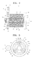
FIG. 2 is a side view of the apparatus ofFIG. 1 ; -
FIG. 3 is a front view of the apparatus illustrated inFIG. 1 ; and -
FIG. 4 is a flowchart exemplifying a bellows type hose-forming operation of the apparatus illustrated inFIG. 1 . - Throughout the drawings, the same drawing reference numerals will be understood to refer to the same elements, features, and structures.
- Hereinafter, an apparatus for fabricating a bellows type hose and a fabrication method thereof according to an exemplary embodiment of the present disclosure will now be described in greater detail with reference to the accompanying drawings.
-
FIGS. 1 through 3 are views exemplifying a bellows type hose-fabricatingapparatus 10 according to an exemplary embodiment of the present disclosure. - As illustrated in
FIG. 1 , the bellows type hose-fabricatingapparatus 10 according to the exemplary embodiment of the present disclosure includes apower generating unit 11, anouter mold 20, and a power transmittingunit 40. - The
power generating unit 11 is made up of apower generating gear 13 connected to a power generating source (not illustrated) through a gear train (not illustrated). Thepower generating gear 13 may be connected to the power generating source through a belt apparatus including a driving pulley (not illustrated) formed on a driving axis of the power generating source, a driven pulley (not illustrated) formed on anaxis 14 of the power generatinggear 13 and a belt connecting the driving pulley and the driven pulley, instead of the gear train. - The
outer mold 20, which formsspiral folds 16a on a hollow-cylindricalbasic material 16 of synthetic resin formed and conveyed by an injection molding unit (not illustrated), is provided with at least one, for example, three folds-forminggears basic material 16 by injecting a molten synthetic resin onto a cylindrical jig (not illustrated) by using a fluid of high pressure supplied through a fluid supplying passage (not illustrated), a detailed description thereof will be omitted. As used herein the term "high pressure" shall mean pressure of 2-5kg/cm2. - Each of the folds-forming
gears part basic material 16 to formspiral folds 16a on the hollow-cylindricalbasic material 16. To form thespiral folds 16a on the hollow-cylindricalbasic material 16, the waved folds-formingpart basic material 16 formed and conveyed by the injection molding unit in a state where it is completely not hardened, the waved folds-formingpart basic material 16. - The three folds-forming
gears basic material 16. For this, first andsecond ends balance supporting part 27 inside a rotation transmittinggear 41 of thepower transmitting unit 40 and afixed gear 33 of a fixed supporting 30, which will be described. Thebalance supporting part 27 is provided with first and secondcircular rings second ends gears circular rings holes second ends gears - To support and guide the second ends of the folds-forming
gears circular ring 29 to allow them to stably rotate and revolve in a folds-forming operation, a fixed supportingpart 30 is disposed on the side of the second ends of the folds-forminggears part 30 is made up of a fixedgear 33, a lower part of which is fixed on anapparatus body 18. The fixedgear 33 has innercircumferential teeth 34 formed on an inner circumferential surface thereof to engage with supportinggears 35 and 36 (only two supporting gears among the three supporting gears illustrated) formed on the second ends of the folds-forminggears - The
power transmitting unit 40, which transmits a power transmitted from thepower generating gear 13 of thepower generating unit 11 to the folds-forminggears outer mold 20, is provided with arotation transmitting gear 41. Therotation transmitting gear 41 has outercircumferential teeth 41 a formed on an outer circumferential surface thereof to engage with thepower generating gear 14, and a innercircumferential teeth 41 b formed on an inner circumferential surface thereof to engage with drivengears gears - Hereinafter, an operation of the bellows type
hose fabricating apparatus 10 constructed as described above will be described with reference toFIGS. 1 through 4 . - First, a hollow-cylindrical
basic material 16 is continuously formed by an injection molding unit, which is not illustrated (S1). - Subsequently, the formed hollow-cylindrical
basic material 16 is conveyed in a direction of arrow A ofFIGS. 1 and2 toward the folds-forminggears - At this time, a power generated from the power generating source, such as a motor, is transmitted to the
power generating gear 13 through the gear train, so that it rotates thepower generating gear 13 in one direction, for example, a clockwise direction ofFIG. 1 . As thepower generating gear 13 is rotated in the clockwise direction, therotation transmitting gear 41 having the outercircumferential teeth 41 a engaged with thepower generating gear 13 is rotated in a counterclockwise direction. As a result, the three folds-forminggears circumferential teeth 41 b of therotation transmitting gear 41 is begin to rotate while revolving in the counterclockwise direction by a rotating force of therotation transmitting gear 41. - Under this state, when the front end of the hollow-cylindrical
basic material 16 reaches the folds-forminggears outer mold 20, it advances into a center of the three folds-forminggears - When the front end of the hollow-cylindrical
basic material 16 advances into the center of the three folds-forminggears gears basic material 16. Thus, the folds-forming grooves in the spiral shape of the waved folds-formingparts basic material 16 to form spiral folds 16a on the outer circumferential surface of the hollow-cylindrical basic material 16 (S3). - At this time, a fluid is supplied at high pressure onto an inner circumferential surface of the hollow-cylindrical
basic material 16 through a fluid supplying passage of the injection molding unit. As a result, a portion of the hollow-cylindricalbasic material 16 located on the side of the folds-forming grooves in the form of spiral shape of the waved folds-formingparts basic material 16. - In addition, at this time, the folds-forming
gears basic material 16 by the folds-forminggears basic material 16, which is conveyed by the injection molding unit. That is, a driving speed of thepower generating source 11, such as the motor, and a gear ratio of thepower generating gear 13, therotation transmitting gear 41 and the folds-forminggear basic material 16, the pitch forming speed of the spiral folds 16a is slower than the conveying speed of the hollow-cylindricalbasic material 16. Also, the driving speed of the power generating source and the gear ratio of thepower generating gear 13, therotation transmitting gear 41 and the folds-forminggear basic material 16, the pitch forming speed of the spiral folds 16a is faster than the conveying speed of the hollow-cylindricalbasic material 16. - When the hollow-cylindrical
basic material 16 completely passes through the waved folds-formingparts gear basic material 16 is finished. - After that, the hollow-cylindrical
basic material 16 on which the spiral folds 16a are formed, that is, the finally formed bellows type hose is cooled, cut in a proper size and then stored (S4). - As apparent from the foregoing description, according to the exemplary embodiment of the present disclosure, the bellows type hose-fabricating apparatus and the fabrication method thereof continuously form the spiral folds on the hollow-cylindrical basic material with the folds-forming groove in the form of spiral shape of the waved folds-forming part rotating according to the rotation of the folds-forming gears in the folds-forming operation. Accordingly, the problem that the joint, such as the parting line, the step, etc., is formed on the hollow-cylindrical basic material due to the folds-forming process independently or non-continuously performed as in the conventional bellows type hose-fabricating apparatus, is prevented, thereby allowing the bellows type hose to improve in quality.
- Further, the bellows type hose-fabricating apparatus and the fabrication method thereof according to the exemplary embodiment of the present disclosure form the folds on the hollow-cylindrical basic material by the folds-forming gears of the outer mold rotating while revolving around the hollow-cylindrical basic material in the state where the hollow-cylindrical basic material is conveyed. Accordingly, there is no need for the outer mold to return to the original position after the folds-forming operation as in the conventional flexible tube-fabricating apparatus, and it is possible to machine a relatively elongated hollow-cylindrical basic material even though the apparatus does not become bigger.
- Also, the bellows type hose-fabricating apparatus and the fabrication method thereof according to an exemplary embodiment of the present disclosure performs the injection molding process for forming the hollow-cylindrical basic material and the folds-forming process in succession. Accordingly, there is no need for a separate inner mold for supplying a fluid at high pressure into the hollow-cylindrical basic material when the waved folds are formed on the hollow-cylindrical basic material, thereby allowing the apparatus to reduce fabrication costs for the bellows type hose.
- Although representative embodiment of the present disclosure has been shown and described in order to exemplify the principle of the present disclosure, the present disclosure is not limited to the specific embodiment. It will be understood that various modifications and changes can be made by one skilled in the art without departing from the spirit and scope of the invention as defined by the appended claims. Therefore, it shall be considered that such modifications, changes and equivalents thereof are all included within the scope of the present disclosure.
Claims (17)
- An apparatus for fabricating a bellows type hose from a hollow-cylindrical basic material, the apparatus comprising:a power generating unit;an outer mold having at least one folds-forming gear disposed to rotate while revolving around the hollow-cylindrical basic material and thus to form folds on the hollow-cylindrical basic material, the at least one folds-forming gear having a waved folds-forming part formed on an outer circumferential surface thereof; anda power transmitting unit to transmit a power of the power generating unit to the at least one folds-forming gear of the outer mold.
- The apparatus as claimed in claim 1, wherein the power generating unit comprises a power generating gear connected to a power generating source through a gear train or a belt.
- The apparatus as claimed in claim 1 or 2, wherein the outer mold further comprises:a balance supporting part to rotatably support both ends of the at least one folds-forming gear in an equally-spaced circle shape; anda fixed supporting part to support the at least one folds-forming gear and to guide the rotation and the revolution of the at least one folds-forming gear.
- The apparatus as claimed in claim 3, wherein the balance supporting part comprises first and second circular rings to rotatably support the both ends of the at least one folds-forming gear.
- The apparatus as claimed in claim 3 or 4, wherein the fixed supporting part comprises a fixed gear fixed on an apparatus body and having inner circumferential teeth formed in an inner circumferential surface thereof to engage with a supporting gear formed on one end of the at least one folds-forming gear.
- The apparatus as claimed in any of claims 2 to 5, wherein the waved folds-forming part comprises a folds-forming groove formed in a spiral shape with at least one pitch.
- The apparatus as claimed in claim 6, wherein the waved folds-forming part is formed in a length of 10-500 mm.
- The apparatus as claimed in any of claims 1 to 7, wherein the power transmitting unit comprises a rotation transmitting part having outer circumferential teeth formed on an outer circumferential surface thereof to engage with a power generating gear of the power generating unit and inner circumferential teeth formed on an inner circumferential surface thereof to engage with a driven gear formed on the other end of the at least one folds-forming gear.
- The apparatus as claimed in any of claims 1 to 8, wherein the at least one folds-forming gear comprises three folds-forming gears disposed in an equally-spaced circle shape around the hollow-cylindrical basic material.
- A method for fabricating a bellows type hose, comprising:conveying a hollow-cylindrical basic material to at least one folds-forming gear having a waved folds-forming part formed on an outer circumferential surface thereof; anddriving the at least one folds-forming gear to allow the at least one folds-forming gear to form folds on the hollow-cylindrical basic material by rotating while revolving around the hollow-cylindrical basic material.
- The method as claimed in claim 10, wherein the conveying comprises conveying the hollow-cylindrical basic material from an injection molding unit for forming the hollow-cylindrical basic material, to bring the hollow-cylindrical basic material into contact with the waved folds-forming part.
- The method as claimed in any of claims 10 and 11, wherein the at least one folds-forming gear comprises three folds-forming gears disposed in an equally-spaced circle shape around the hollow-cylindrical basic material, and wherein the conveying comprises conveying the hollow-cylindrical basic material into a center of the three folds-forming gears to bring the hollow-cylindrical basic material into contact with waved folds-forming parts of the three folds-forming gears.
- The method as claimed in any of claims 10 to 12, wherein the driving comprises driving the at least one folds-forming gear having a folds-forming groove formed in a spiral shape with at least one pitch as the waved folds-forming part, to allow the at least one folds-forming gear to form spiral folds on the hollow-cylindrical basic material.
- The method as claimed in any of claims 10 to 13, wherein the at least one folds-forming gear comprises three folds-forming gears disposed in an equally-spaced circle shape around the hollow-cylindrical basic material.
- The method as claimed in any of claims 10 to 14, wherein a fluid is supplied at high pressure into the hollow-cylindrical basic material by an injection molding unit for forming the hollow-cylindrical basic material.
- The method as claimed in any of claims 10 to 15, wherein the driving comprises driving the at least one folds-forming gear in such a manner that a pitch forming speed of the spiral folds, which are formed on the hollow-cylindrical basic material by the at least one folds-forming gear, is equal to or different from a conveying speed of the hollow-cylindrical basic material, which is conveyed by an injection molding unit, according to a thickness of the bellows type hose to be finally formed.
- The method as claimed in any of claims 10 to 16, wherein the driving comprises driving the at least one folds-forming gear, so that the pitch forming speed of the spiral folds is slower than the conveying speed of the hollow-cylindrical basic material, when the thickness of the bellows type hose to be finally formed is larger than that of the hollow-cylindrical basic material, and driving the at least one folds-forming gear, so that the pitch forming speed of the spiral folds is faster than the conveying speed of the hollow-cylindrical basic material, when the thickness of the bellows type hose to be finally formed is smaller than that of the hollow-cylindrical basic material.
Applications Claiming Priority (1)
| Application Number | Priority Date | Filing Date | Title |
|---|---|---|---|
| KR1020070070672A KR20090007058A (en) | 2007-07-13 | 2007-07-13 | Corrugated pipe manufacturing device and manufacturing method |
Publications (1)
| Publication Number | Publication Date |
|---|---|
| EP2014446A1 true EP2014446A1 (en) | 2009-01-14 |
Family
ID=39404041
Family Applications (1)
| Application Number | Title | Priority Date | Filing Date |
|---|---|---|---|
| EP08103009A Withdrawn EP2014446A1 (en) | 2007-07-13 | 2008-03-27 | Apparatus for fabricating bellows type hose and fabrication method thereof |
Country Status (5)
| Country | Link |
|---|---|
| US (1) | US20090014906A1 (en) |
| EP (1) | EP2014446A1 (en) |
| JP (1) | JP2009018571A (en) |
| KR (1) | KR20090007058A (en) |
| RU (1) | RU2008119098A (en) |
Cited By (2)
| Publication number | Priority date | Publication date | Assignee | Title |
|---|---|---|---|---|
| WO2017178047A1 (en) * | 2016-04-13 | 2017-10-19 | Kongsberg Actuation Systems Ltd. | Method and apparatus for forming a corrugated fluoropolymer tube |
| FR3119433A1 (en) * | 2021-02-04 | 2022-08-05 | Akwel | Fluid transfer component with flexible bellows region. |
Citations (4)
| Publication number | Priority date | Publication date | Assignee | Title |
|---|---|---|---|---|
| GB986226A (en) | 1960-11-14 | 1965-03-17 | Adolf Rohde | Methods of producing hose |
| US4043161A (en) | 1975-11-07 | 1977-08-23 | Astrolab, Inc. | Apparatus for forming corrugations of "zero" pitch in coaxial cable |
| US4053274A (en) | 1975-01-28 | 1977-10-11 | Lemelson Jerome H | Tube wall forming apparatus |
| KR960004047Y1 (en) | 1993-12-31 | 1996-05-17 | 동아금속 플렉시블 주식회사 | Corrugate tube processing machine |
Family Cites Families (4)
| Publication number | Priority date | Publication date | Assignee | Title |
|---|---|---|---|---|
| US3532580A (en) * | 1965-11-15 | 1970-10-06 | Shiro Kanao | Method and apparatus for continuously manufacturing synthetic resin pipe |
| US3756004A (en) * | 1970-09-21 | 1973-09-04 | Gore & Ass | Method and apparatus for insulating electrical conductors |
| NZ208302A (en) * | 1983-06-08 | 1986-04-11 | Toyo Kagaku Kk | Manufacturing corrugated plastics tubes with smooth inner wall |
| US6840074B2 (en) * | 1999-04-21 | 2005-01-11 | Tojo Kamino | Pipe and heat exchanger, pipe manufacturing device, and pipe manufacturing method |
-
2007
- 2007-07-13 KR KR1020070070672A patent/KR20090007058A/en not_active Withdrawn
-
2008
- 2008-01-04 US US12/006,671 patent/US20090014906A1/en not_active Abandoned
- 2008-03-27 EP EP08103009A patent/EP2014446A1/en not_active Withdrawn
- 2008-05-12 JP JP2008125145A patent/JP2009018571A/en active Pending
- 2008-05-15 RU RU2008119098/12A patent/RU2008119098A/en not_active Application Discontinuation
Patent Citations (4)
| Publication number | Priority date | Publication date | Assignee | Title |
|---|---|---|---|---|
| GB986226A (en) | 1960-11-14 | 1965-03-17 | Adolf Rohde | Methods of producing hose |
| US4053274A (en) | 1975-01-28 | 1977-10-11 | Lemelson Jerome H | Tube wall forming apparatus |
| US4043161A (en) | 1975-11-07 | 1977-08-23 | Astrolab, Inc. | Apparatus for forming corrugations of "zero" pitch in coaxial cable |
| KR960004047Y1 (en) | 1993-12-31 | 1996-05-17 | 동아금속 플렉시블 주식회사 | Corrugate tube processing machine |
Cited By (5)
| Publication number | Priority date | Publication date | Assignee | Title |
|---|---|---|---|---|
| WO2017178047A1 (en) * | 2016-04-13 | 2017-10-19 | Kongsberg Actuation Systems Ltd. | Method and apparatus for forming a corrugated fluoropolymer tube |
| US11370186B2 (en) | 2016-04-13 | 2022-06-28 | Kongsberg Actuation Systems Ltd. | Method and apparatus for forming a corrugated fluoropolymer tube |
| FR3119433A1 (en) * | 2021-02-04 | 2022-08-05 | Akwel | Fluid transfer component with flexible bellows region. |
| WO2022167769A1 (en) | 2021-02-04 | 2022-08-11 | Akwel | Fluid transfer component with flexible region forming bellows |
| CN116917653A (en) * | 2021-02-04 | 2023-10-20 | 阿克韦尔公司 | Fluid transfer component having flexible areas forming bellows |
Also Published As
| Publication number | Publication date |
|---|---|
| JP2009018571A (en) | 2009-01-29 |
| US20090014906A1 (en) | 2009-01-15 |
| KR20090007058A (en) | 2009-01-16 |
| RU2008119098A (en) | 2009-11-20 |
Similar Documents
| Publication | Publication Date | Title |
|---|---|---|
| CN100515317C (en) | Flexible Channels for Endoscopes | |
| KR860000805B1 (en) | Apparatus and method manufacturing corrugated tubes | |
| JP2006508818A (en) | Extruder for producing molten plastic material | |
| JP2004237352A (en) | Wire spring forming equipment | |
| KR100388542B1 (en) | Cutting blade bending apparatus capable of performing accurate acute angle | |
| US20090014906A1 (en) | Apparatus for fabricating bellows type hose and fabrication method thereof | |
| JP4986179B2 (en) | Spinning method and apparatus | |
| US9943915B2 (en) | Forming closely spaced annular internal corrugations in circular waveguides | |
| WO2001028756A1 (en) | Spiral hose making apparatus and method | |
| WO1994003319A1 (en) | Method of and apparatus for knead-extruding plastic resin by alternate extrusion using plurality of cylinders | |
| KR100342135B1 (en) | Double Straw Forming Appartus | |
| KR100194899B1 (en) | Ribbed hose manufacturing equipment | |
| KR20120006333A (en) | Hybrid type continuous pipe manufacturing device and manufacturing equipment using the same | |
| KR20150056737A (en) | Continuous composite pipe forming methods | |
| CN115518998B (en) | A head half pipe forming machine | |
| US3974019A (en) | Apparatus for manufacturing plastic pipes | |
| JPH046460B2 (en) | ||
| KR20100066981A (en) | Facility for manufacturing a pipe continuously | |
| KR890002878B1 (en) | Producing apparatus of a metallic fold pipe | |
| CN209239456U (en) | A kind of vertical correction mechanism based on gear | |
| CN109016547A (en) | Telescopic pipet forms assembly line | |
| KR900011343Y1 (en) | Equipment for manufacturing corrugated tubes | |
| CN111483139B (en) | Reciprocating wire winding machine for 3D printer | |
| KR200339406Y1 (en) | Machine for manufacturing spring for keeping a form of spring hose for a vacuum cleaner | |
| JPH02155717A (en) | Manufacture of synthetic resin tube |
Legal Events
| Date | Code | Title | Description |
|---|---|---|---|
| PUAI | Public reference made under article 153(3) epc to a published international application that has entered the european phase |
Free format text: ORIGINAL CODE: 0009012 |
|
| AK | Designated contracting states |
Kind code of ref document: A1 Designated state(s): AT BE BG CH CY CZ DE DK EE ES FI FR GB GR HR HU IE IS IT LI LT LU LV MC MT NL NO PL PT RO SE SI SK TR |
|
| AX | Request for extension of the european patent |
Extension state: AL BA MK RS |
|
| AKX | Designation fees paid | ||
| REG | Reference to a national code |
Ref country code: DE Ref legal event code: 8566 |
|
| STAA | Information on the status of an ep patent application or granted ep patent |
Free format text: STATUS: THE APPLICATION IS DEEMED TO BE WITHDRAWN |
|
| 18D | Application deemed to be withdrawn |
Effective date: 20090715 |