EP2012908B1 - Method of potting hollow fibers - Google Patents
Method of potting hollow fibers Download PDFInfo
- Publication number
- EP2012908B1 EP2012908B1 EP07761241.4A EP07761241A EP2012908B1 EP 2012908 B1 EP2012908 B1 EP 2012908B1 EP 07761241 A EP07761241 A EP 07761241A EP 2012908 B1 EP2012908 B1 EP 2012908B1
- Authority
- EP
- European Patent Office
- Prior art keywords
- membranes
- potting
- cavity
- adhesive
- layer
- Prior art date
- Legal status (The legal status is an assumption and is not a legal conclusion. Google has not performed a legal analysis and makes no representation as to the accuracy of the status listed.)
- Active
Links
Images


Classifications
-
- B—PERFORMING OPERATIONS; TRANSPORTING
- B29—WORKING OF PLASTICS; WORKING OF SUBSTANCES IN A PLASTIC STATE IN GENERAL
- B29C—SHAPING OR JOINING OF PLASTICS; SHAPING OF MATERIAL IN A PLASTIC STATE, NOT OTHERWISE PROVIDED FOR; AFTER-TREATMENT OF THE SHAPED PRODUCTS, e.g. REPAIRING
- B29C45/00—Injection moulding, i.e. forcing the required volume of moulding material through a nozzle into a closed mould; Apparatus therefor
- B29C45/14—Injection moulding, i.e. forcing the required volume of moulding material through a nozzle into a closed mould; Apparatus therefor incorporating preformed parts or layers, e.g. injection moulding around inserts or for coating articles
- B29C45/14336—Coating a portion of the article, e.g. the edge of the article
- B29C45/14385—Coating a portion of a bundle of inserts, e.g. making brushes
-
- B—PERFORMING OPERATIONS; TRANSPORTING
- B01—PHYSICAL OR CHEMICAL PROCESSES OR APPARATUS IN GENERAL
- B01D—SEPARATION
- B01D63/00—Apparatus in general for separation processes using semi-permeable membranes
- B01D63/02—Hollow fibre modules
- B01D63/021—Manufacturing thereof
- B01D63/022—Encapsulating hollow fibres
- B01D63/0221—Encapsulating hollow fibres using a mould
-
- B—PERFORMING OPERATIONS; TRANSPORTING
- B01—PHYSICAL OR CHEMICAL PROCESSES OR APPARATUS IN GENERAL
- B01D—SEPARATION
- B01D63/00—Apparatus in general for separation processes using semi-permeable membranes
- B01D63/02—Hollow fibre modules
- B01D63/021—Manufacturing thereof
- B01D63/022—Encapsulating hollow fibres
- B01D63/023—Encapsulating materials
-
- B—PERFORMING OPERATIONS; TRANSPORTING
- B01—PHYSICAL OR CHEMICAL PROCESSES OR APPARATUS IN GENERAL
- B01D—SEPARATION
- B01D63/00—Apparatus in general for separation processes using semi-permeable membranes
- B01D63/02—Hollow fibre modules
- B01D63/024—Hollow fibre modules with a single potted end
-
- B—PERFORMING OPERATIONS; TRANSPORTING
- B01—PHYSICAL OR CHEMICAL PROCESSES OR APPARATUS IN GENERAL
- B01D—SEPARATION
- B01D69/00—Semi-permeable membranes for separation processes or apparatus characterised by their form, structure or properties; Manufacturing processes specially adapted therefor
- B01D69/08—Hollow fibre membranes
-
- B—PERFORMING OPERATIONS; TRANSPORTING
- B29—WORKING OF PLASTICS; WORKING OF SUBSTANCES IN A PLASTIC STATE IN GENERAL
- B29C—SHAPING OR JOINING OF PLASTICS; SHAPING OF MATERIAL IN A PLASTIC STATE, NOT OTHERWISE PROVIDED FOR; AFTER-TREATMENT OF THE SHAPED PRODUCTS, e.g. REPAIRING
- B29C70/00—Shaping composites, i.e. plastics material comprising reinforcements, fillers or preformed parts, e.g. inserts
- B29C70/68—Shaping composites, i.e. plastics material comprising reinforcements, fillers or preformed parts, e.g. inserts by incorporating or moulding on preformed parts, e.g. inserts or layers, e.g. foam blocks
- B29C70/84—Shaping composites, i.e. plastics material comprising reinforcements, fillers or preformed parts, e.g. inserts by incorporating or moulding on preformed parts, e.g. inserts or layers, e.g. foam blocks by moulding material on preformed parts to be joined
-
- B—PERFORMING OPERATIONS; TRANSPORTING
- B29—WORKING OF PLASTICS; WORKING OF SUBSTANCES IN A PLASTIC STATE IN GENERAL
- B29K—INDEXING SCHEME ASSOCIATED WITH SUBCLASSES B29B, B29C OR B29D, RELATING TO MOULDING MATERIALS OR TO MATERIALS FOR MOULDS, REINFORCEMENTS, FILLERS OR PREFORMED PARTS, e.g. INSERTS
- B29K2101/00—Use of unspecified macromolecular compounds as moulding material
- B29K2101/10—Thermosetting resins
-
- B—PERFORMING OPERATIONS; TRANSPORTING
- B29—WORKING OF PLASTICS; WORKING OF SUBSTANCES IN A PLASTIC STATE IN GENERAL
- B29K—INDEXING SCHEME ASSOCIATED WITH SUBCLASSES B29B, B29C OR B29D, RELATING TO MOULDING MATERIALS OR TO MATERIALS FOR MOULDS, REINFORCEMENTS, FILLERS OR PREFORMED PARTS, e.g. INSERTS
- B29K2101/00—Use of unspecified macromolecular compounds as moulding material
- B29K2101/12—Thermoplastic materials
-
- B—PERFORMING OPERATIONS; TRANSPORTING
- B29—WORKING OF PLASTICS; WORKING OF SUBSTANCES IN A PLASTIC STATE IN GENERAL
- B29L—INDEXING SCHEME ASSOCIATED WITH SUBCLASS B29C, RELATING TO PARTICULAR ARTICLES
- B29L2031/00—Other particular articles
- B29L2031/14—Filters
-
- B—PERFORMING OPERATIONS; TRANSPORTING
- B29—WORKING OF PLASTICS; WORKING OF SUBSTANCES IN A PLASTIC STATE IN GENERAL
- B29L—INDEXING SCHEME ASSOCIATED WITH SUBCLASS B29C, RELATING TO PARTICULAR ARTICLES
- B29L2031/00—Other particular articles
- B29L2031/755—Membranes, diaphragms
Definitions
- This specification may relate to methods of potting hollow fiber membranes and to methods of making headers for modules of hollow fiber membranes.
- a large number of thin hollow fibres must be fixed to a header such that their outer surfaces are each completely sealed to the outside of the header but their lumens are open to an inner space in the header.
- the inner space of the header is then connected to a source of suction or pressure to create a transmembrane pressure across the walls of the membranes and carry fluids to or from the lumens of the membranes.
- a continuous hollow fibre is made into a fabric such that adjacent lengths of the fibres are spaced apart from each other and do not have open ends.
- An edge of the fabric is inserted into a pot of liquid resin which is centrifuged or vibrated as it cures to encourage flow into the spaces between the fibres.
- the block of resin and fibre is cut to separate the fabric into individual lengths of fibres having open ends.
- the block of resin is then glued or attached through gaskets to the remainder of a header.
- an elastic pipe is used to make a header.
- An aperture is cut in the pipe and a weir is built up around the aperture. Open ends of hollow fibre membranes are inserted into the aperture by first pulling the aperture open and then allowing it to close on the membranes. Liquid resin is poured over the ends of the membranes and retained in placed by the weir until it cures. Surface tension prevents the resin from flowing through the aperture in spaces between adjacent fibres.
- WO 2006/045191 which is state of the art under A.54(3) EPC, describes a header for a module of hollow fiber membranes and a method of potting hollow fibres in a closed cavity, the fibres being prefixed.
- WO 01/85315 describes a gel potting method for producing filtering hollow fibre membranes.
- US 4138460 describes a method for forming tubesheets in an enclosed potting cavity on hollow fibre tows and forming corresponding hollow fibre bundle assemblies.
- curable, resinous liquids creates various drawbacks.
- curable materials such as polyurethane, epoxy or silicone are expensive.
- the time required to cure these materials is also long, typically at least 10 minutes and more often hours because fast curing of a large block of resin creates excess heat.
- the resins may also require careful mixing or curing procedures, or may release harmful chemicals as they cure. Wicking of the liquid resin up the length of the fibers prior to curing can also be a problem.
- the membranes are provided in a bundle having a layer of a compressible material surrounding the membranes in a plane spaced from the ends of the membranes.
- the layer of compressible material may be formed by placing layers of hot melt adhesive over sheets of fibers, optionally stacking multiple sheets of the fibers together.
- the fibers are then placed in a mold which compresses the band of compressible material to form a generally sealed cavity containing the fibers.
- a molten potting material is injected into the cavity to surround the membranes.
- the potting material is cooled in the mold and hardens forming a block of solid potting material sealingly connected to the membranes.
- two spaced-apart layers of compressible material may be provided on the bundle.
- the mold compresses both layers to provide a cavity between the two layers which is filled with injected potting material. In this case, the fixing liquid does not flow to the ends of the membranes which remain open.
- a method as described above is used to pot the membranes into a block of potting material.
- the potting material is removed from the mold and then cut to re-open the ends of the fibers.
- the block of potting material is then sealed to a header pan to form a permeate collection zone in communication with the fiber ends.
- a block of potting material formed between two bands of compressible material is sealed to a header pan with the open ends of the fibers, and the layer of compressible material closest to them, inside a permeate collection zone.
- a block of potting material is formed between two bands of compressible material while at least the band of compressible material closest to the ends of the membranes is inserted into a header pan.
- both bands of compressible material may be inserted in the header pan.
- the block of potting material is formed in or around, and seals to, the top of the header pan and the membranes at the same time.
- a method of potting hollow fiber membranes may comprise steps of forming a substantially closed cavity around a portion of the membranes near their ends.
- a liquid potting material is injected into the cavity and allowed to solidify in the cavity.
- the potting material may be a thermoplastic or thermoset resin.
- an assembly of potted membranes has a band of adhesive, compressible material and a block of a solidified thermoplastic or reaction injection molded potting material.
- an assembly of potted membranes has two bands of adhesive compressible material and a block of a solidified potting material between the bands.
- an assembly as described above has a block of potting material sealed to a header pan to form a permeate cavity in communication with ends of the membranes.
- Figure 1 shows a sheet 10 of hollow fiber membranes 12.
- the sheet 10 is formed by laying the membranes 12 on a supporting surface, such as a table, so that the membranes 12 are generally parallel to each other but spaced apart from each other, for example from between 0.2 to 2 times their diameter, at least in a potting region 14 near their open ends 16.
- the sheet 10 may be formed by any suitable fabric forming method and have inert fibers running transversely across the membranes 12 to help maintain the membranes 12 in position.
- the sheet 10 may be formed by winding the membranes 12 onto a drum, preferably through a guide that advances across the face of the drum at a speed, relative to the speed of rotation of the drum, which lays the fibers in a spiral around the drum at a desired spacing.
- the membranes 12 may have diameters, for example, between 0.5 and 2.5 mm and there may be, for example, between 50 and 400 membranes 12 in a sheet 10.
- the width of the sheet 10 may be, for example, from 400 mm to 1200 mm and the length of the sheet 10, and its membranes 12, may be, for example, between 200 and 3200 mm.
- the membranes 12 are shown as cut to a shorter length to allow other parts to be shown larger.
- a first layer 18 of a compressible adhesive 20 is placed over the sheet 10 so that the ends 16 of the membranes 12 and the first layer 18 of adhesive 20 are on opposite sides of the potting region 14.
- the adhesive 20 holds the sheet 10 together.
- the adhesive 20 also seals to the entire outer circumference of the membranes 12, although a perfect bubble tight seal does not need to be formed.
- the length, width and thickness of the first layer 18 of adhesive 20 are maintained to a size that will cooperate with a mold to be described below.
- the adhesive 20 may be thermoplastic and applied by first melting it so that it may flow over and around the membranes 12.
- the adhesive 20 may also be melted after applying it to the membranes 12, or molded or shaped while it is molten to provide a layer of more uniform shape or more carefully controlled size.
- the adhesive 20 may also be generally soft, so as to be more easily compressed into a seal with the mold, as will be described below, and to provide a cushioning layer for the membranes 12.
- the adhesive 20 may be of a type normally referred to as hot melt glue, which may be a polyethylene or a blend of ethylene vinyl acetate co-polymers.
- the adhesive may be a resin such as polyurethane or epoxy.
- a second layer 22 of adhesive 20 may also be provided in a manner as described for the first layer 18. However, the second layer 22 is applied between the ends 16 and the potting region 14. The second layer 22 does not cover or fill the ends 16 of the membranes 12.
- the second layer 22 is preferably placed as close as practical to the ends 16 of the membranes 12 without closing the ends 16 to reduce the length of the membranes 12 that will protrude into, and interfere with flows of fluids in, the permeate cavity of a finished header.
- Figure 2 shows a bundle 24 of membranes 12 made by stacking a number of sheets 10, for example between 1 and 30 or between 10 and 20 sheets 10 together.
- the sheets 10 are stacked so that the adhesive layers 18, 22 lay on top of each other to generally form a parallelepiped.
- one or more sheets 10 may be rolled up together to generally form a cylinder or made into other shapes.
- the sheets 10 may be glued, welded or clamped together or simply held together manually or by wrapping a string, wire, band or other wrap around the bundle 24.
- Figure 3 shows the bundle 24 placed into a first mold 30.
- the mold has a first plate 32 and a second plate 34 having contact surfaces 36 and mold surfaces 38.
- the plates 32, 34 are brought towards each other by tightening screws, not shown, in screw holes 40.
- the contact surfaces 36 compress the adhesive layers 18, 22 and create a temporary seal.
- a cavity 44 is formed between the mold surfaces 38 of the plates 32, 34, the adhesive layers 18, 22 and ends (not shown) of the first mold which contact the ends of the adhesive layers 18, 22.
- the potting region 14 of the bundle 24 is inside of the cavity 44.
- One or more inlet nozzles 42 allow molten potting material to be injected into the cavity 44.
- One or more ejector pins 46 may be used to get bundle 24 out from the cavity 44 after potting and secondarily to permit air venting of the cavity 44.
- the cavity 44 is substantially closed in that it surrounds the potting region but for small venting or injection pins.
- molten potting material is injected into the nozzles 42 to fill the cavity 44.
- the adhesive layers 18, 22 prevent the potting material from leaving the cavity 44.
- the potting material flows around the bundle 24 and then penetrates into the spaces between the membranes 12.
- the potting material is then cooled sufficiently quickly to avoid damage to the membranes 12 or excessive melting of the adhesive layers 18, 22.
- the plates 32, 34 may be moved apart from each other to remove the potted bundle 24.
- the inside surfaces of the cavity 44 will have formed substantially all of the exterior surfaces of a solidified mass of potting material.
- the potting material may be one of the several thermoplastic polymers or resins commonly used in injection molding, such as Polypropylene (PP), Polyethylene (PE), High Density Polyethylene (HDPE), moplastic Elastomer (TPE), Thermopastic Polyurethane (TPU), Acrylonitrile Butadiene Styrene (ABS), Polyamide (PA), polystyrene (PS), Polypropylene (PP), Polyethylene Copolymers or Polyolefin based hotmelt polymers or glues, or any of these materials in a filled form, for example glass filled.
- PP Polypropylene
- PE Polyethylene
- HDPE High Density Polyethylene
- TPE moplastic Elastomer
- TPU Thermopastic Polyurethane
- ABS Acrylonitrile Butadiene Styrene
- PA Polyamide
- PS polystyrene
- the membranes 12 may also be of various types of construction known in the art, but must be sufficiently strong to not be flattened by the injected potting material.
- the membranes 12 may be reinforced fibers having a braided support such as membranes made by ZENON Environmental Inc. for ZEEWEEDTM 500 series modules.
- the potting material may have a melting point of 50 °C or more.
- the potted bundle 24 After the potted bundle 24 is removed, it can be attached to a header pan 52. As shown in Figure 5 , the ends 16 of the membranes 12 are inserted into the inside of the permeate pan 52 where a permeate (or feed) cavity 54 is formed.
- the potting material 50 is sealed to the walls 56 of the header pan 52 to close the permeate/feed cavity 54, but for one or more ports 58 in the header pan 52 and the ends 16 of the membranes 12.
- the confection between the permeate pan 52 and the potting material 50 can be made by various methods such as gluing, welding or mechanical fasteners, optionally through a gasket or other intermediate material. Further optionally, the potting material may be cut along line 60 prior to attachment to the header pan 52.
- This may be done, for example, to provide a smooth lower face 62 if the header pan 52 is to be attached to the lower face 62 rather than the sides 64 of the block of potting material 50. Cutting the potting material 50 may also be done when required to re-open the ends 16, of the membranes 12, for example if a lower layer 22 of adhesive 20 were not used in a modified mold used to create a cavity extending from the first layer 18 of adhesive 20 to beyond the ends 16 of the membranes 12.
- Figure 4 shows a second mold 70.
- the second mold 70 is similar to the first mold 30 except that one set of contact surfaces 36 have been configured to accept a pre-made header pan 52.
- the bundle 24 of membranes 12 is inserted into the header pan 52 such that the bottom of the second layer 22 of adhesive 20 is below the top edge of the header pan 52, while the bottom of the first layer 18 of adhesive 20 is above the top edge of the header pan 52.
- a set of contact surfaces compresses and temporarily seals against the first layer 18 of adhesive 20 while another set of contact surfaces 36 presses and temporarily seals against the permeate pan 52 which in turn compresses and seals against the second layer 22 of adhesive 20.
- the region at the top of the permeate pan 52 may be inside permeate pan 52 outside the permeate pan 52, or both.
- the potting material flows between and around the membranes 12 and, when cooled to a solid, seals the membranes 12 relative to each other and to the permeate pan 52.
- the walls of the header pan 52 could be extended upwards to also overlap the first layer 18 of adhesive 20 and provided with a port for the injection of potting material into the space between the walls of the header pan 52.
- the inside of the sides of second mold 70 may then be made flush with the outsides of the header pan 52.
- Injection molding of the potting material as described above can be done at applied pressures in the range from 1-300 bar at temperatures from 20-340 °C or 160-340 °C.
- the potting material should remain a solid of sufficient strength in all intended applications, which could involve contact with fluids of up to 60 °C or more.
- membranes 12, as used in ZEEWEEDTM 500 series modules by Zenon Environmental Inc. were potted in a first mold 30 using 3 types of polypropylene, having melt flow indexes between about 10 g/10 min and 1000 g/10 min. Satisfactory results were obtained in potting bundles 24 having 14 sheets 10 of membranes 12 using temperatures between 195 and 230 °C and injection pressures between 90 and 110 bar.
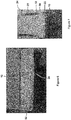
- Figure 6 shows one such potted bundle 24 cut through the polypropylene potting material 50.
- Figure 7 is a photograph of the exterior of another such bundle.
- the processes and apparatuses described above may also be used with chemical reaction resin systems.
- the liquid polymer may be created by mixing two or more chemically reactive components.
- the liquid is still injected under pressure, and may still transfer heat to the mold because of an exothermic reaction, but the potting material solidifies by chemical reaction.
- the methods and apparatuses above may still provide benefits such as avoiding the need for centrifuging or fugitive potting materials while still inhibiting potting material from creeping up the fibers before solidifying.
- injection and cure time may be in the range of 5 minutes or less or 2 minutes or less.
Landscapes
- Chemical & Material Sciences (AREA)
- Engineering & Computer Science (AREA)
- Chemical Kinetics & Catalysis (AREA)
- Manufacturing & Machinery (AREA)
- Mechanical Engineering (AREA)
- Composite Materials (AREA)
- Separation Using Semi-Permeable Membranes (AREA)
Description
- This specification may relate to methods of potting hollow fiber membranes and to methods of making headers for modules of hollow fiber membranes.
- The following description does not admit or imply that the apparatus or method discussed below is citable as prior art or part of the general knowledge of a person skilled in the art in any particular country.
- In order to filter or permeate with hollow fibre membranes, a large number of thin hollow fibres must be fixed to a header such that their outer surfaces are each completely sealed to the outside of the header but their lumens are open to an inner space in the header. The inner space of the header is then connected to a source of suction or pressure to create a transmembrane pressure across the walls of the membranes and carry fluids to or from the lumens of the membranes.
- In
U.S. Pat. No. 5,639,373 , the ends of an array of fibres are submerged in a fugitive liquid, such as a wax, until the fugitive liquid solidifies around them. A fixing liquid, such as a resin, is then poured over the fugitive liquid and allowed to harden around the membranes. The fugitive liquid is then removed, for example by heating or by dissolution, leaving the lumens of the membranes open to the space formerly occupied by the fugitive liquid. InU.S. Pat. No. 6,042,677 , a similar process is used but the array of fibres is held in a bed of powder which is used in place of the solidified fugitive liquid. - In
U.S. Pat. No. 5,922,201 , a continuous hollow fibre is made into a fabric such that adjacent lengths of the fibres are spaced apart from each other and do not have open ends. An edge of the fabric is inserted into a pot of liquid resin which is centrifuged or vibrated as it cures to encourage flow into the spaces between the fibres. After the resin is cured, the block of resin and fibre is cut to separate the fabric into individual lengths of fibres having open ends. The block of resin is then glued or attached through gaskets to the remainder of a header. - In European Patent Application No.
EP 0 931 582 , an elastic pipe is used to make a header. An aperture is cut in the pipe and a weir is built up around the aperture. Open ends of hollow fibre membranes are inserted into the aperture by first pulling the aperture open and then allowing it to close on the membranes. Liquid resin is poured over the ends of the membranes and retained in placed by the weir until it cures. Surface tension prevents the resin from flowing through the aperture in spaces between adjacent fibres. -
WO 2006/045191 , which is state of the art under A.54(3) EPC, describes a header for a module of hollow fiber membranes and a method of potting hollow fibres in a closed cavity, the fibres being prefixed.WO 01/85315 US 4138460 describes a method for forming tubesheets in an enclosed potting cavity on hollow fibre tows and forming corresponding hollow fibre bundle assemblies. - The following summary is intended to introduce the reader to the specification, but not to define the invention. The invention is defined by claim 1. The inventors have observed various difficulties with prior art potting methods. In particular, the use of curable, resinous liquids creates various drawbacks. For example, curable materials such as polyurethane, epoxy or silicone are expensive. The time required to cure these materials is also long, typically at least 10 minutes and more often hours because fast curing of a large block of resin creates excess heat. The resins may also require careful mixing or curing procedures, or may release harmful chemicals as they cure. Wicking of the liquid resin up the length of the fibers prior to curing can also be a problem.
- In a method of potting hollow fiber membranes, the membranes are provided in a bundle having a layer of a compressible material surrounding the membranes in a plane spaced from the ends of the membranes. The layer of compressible material may be formed by placing layers of hot melt adhesive over sheets of fibers, optionally stacking multiple sheets of the fibers together. The fibers are then placed in a mold which compresses the band of compressible material to form a generally sealed cavity containing the fibers. A molten potting material is injected into the cavity to surround the membranes. The potting material is cooled in the mold and hardens forming a block of solid potting material sealingly connected to the membranes. Optionally, two spaced-apart layers of compressible material may be provided on the bundle. The mold compresses both layers to provide a cavity between the two layers which is filled with injected potting material. In this case, the fixing liquid does not flow to the ends of the membranes which remain open.
- In a method of making a header having potted hollow fiber membranes, a method as described above is used to pot the membranes into a block of potting material. In one method, the potting material is removed from the mold and then cut to re-open the ends of the fibers. The block of potting material is then sealed to a header pan to form a permeate collection zone in communication with the fiber ends. In another method, a block of potting material formed between two bands of compressible material is sealed to a header pan with the open ends of the fibers, and the layer of compressible material closest to them, inside a permeate collection zone. In another method, a block of potting material is formed between two bands of compressible material while at least the band of compressible material closest to the ends of the membranes is inserted into a header pan. Optionally, both bands of compressible material may be inserted in the header pan. In this way, the block of potting material is formed in or around, and seals to, the top of the header pan and the membranes at the same time.
- A method of potting hollow fiber membranes may comprise steps of forming a substantially closed cavity around a portion of the membranes near their ends. A liquid potting material is injected into the cavity and allowed to solidify in the cavity. The potting material may be a thermoplastic or thermoset resin.
- The specification also describes potted membranes or headers. In some cases, an assembly of potted membranes has a band of adhesive, compressible material and a block of a solidified thermoplastic or reaction injection molded potting material. In some cases an assembly of potted membranes has two bands of adhesive compressible material and a block of a solidified potting material between the bands. In other cases, an assembly as described above has a block of potting material sealed to a header pan to form a permeate cavity in communication with ends of the membranes.
- Examples of embodiments of the invention or inventions will be described below with reference to the following figures.
-
Figure 1 shows a plan view of a layer of adhesive compressible material placed on a sheet of fibers. -
Figure 2 shows an isometric view of sheets of fibers ofFigure 1 assembled into a larger bundle of fibers having a layer of adhesive, compressible material. -
Figure 3 is a cutaway isometric view of the bundle ofFigure 2 inserted into a first mold. -
Figure 4 shows a cutaway isometric view of the bundle ofFigure 2 inserted into a second mold. -
Figure 5 shows a cutaway view of a potted bundle of membranes attached to a header pan. -
Figure 6 is a photograph of a bundle of potted fibers cut through the potting material. -
Figure 7 is a picture of an assembly of potted membranes. -
Figure 1 shows asheet 10 ofhollow fiber membranes 12. Thesheet 10 is formed by laying themembranes 12 on a supporting surface, such as a table, so that themembranes 12 are generally parallel to each other but spaced apart from each other, for example from between 0.2 to 2 times their diameter, at least in apotting region 14 near their open ends 16. Optionally, thesheet 10 may be formed by any suitable fabric forming method and have inert fibers running transversely across themembranes 12 to help maintain themembranes 12 in position. Further optionally, thesheet 10 may be formed by winding themembranes 12 onto a drum, preferably through a guide that advances across the face of the drum at a speed, relative to the speed of rotation of the drum, which lays the fibers in a spiral around the drum at a desired spacing. Themembranes 12 may have diameters, for example, between 0.5 and 2.5 mm and there may be, for example, between 50 and 400membranes 12 in asheet 10. The width of thesheet 10 may be, for example, from 400 mm to 1200 mm and the length of thesheet 10, and itsmembranes 12, may be, for example, between 200 and 3200 mm. In various Figures, themembranes 12 are shown as cut to a shorter length to allow other parts to be shown larger. - A
first layer 18 of a compressible adhesive 20 is placed over thesheet 10 so that the ends 16 of themembranes 12 and thefirst layer 18 of adhesive 20 are on opposite sides of thepotting region 14. The adhesive 20 holds thesheet 10 together. The adhesive 20 also seals to the entire outer circumference of themembranes 12, although a perfect bubble tight seal does not need to be formed. The length, width and thickness of thefirst layer 18 of adhesive 20 are maintained to a size that will cooperate with a mold to be described below. The adhesive 20 may be thermoplastic and applied by first melting it so that it may flow over and around themembranes 12. The adhesive 20 may also be melted after applying it to themembranes 12, or molded or shaped while it is molten to provide a layer of more uniform shape or more carefully controlled size. The adhesive 20 may also be generally soft, so as to be more easily compressed into a seal with the mold, as will be described below, and to provide a cushioning layer for themembranes 12. For example, the adhesive 20 may be of a type normally referred to as hot melt glue, which may be a polyethylene or a blend of ethylene vinyl acetate co-polymers. Alternately, the adhesive may be a resin such as polyurethane or epoxy. Optionally, asecond layer 22 of adhesive 20 may also be provided in a manner as described for thefirst layer 18. However, thesecond layer 22 is applied between theends 16 and thepotting region 14. Thesecond layer 22 does not cover or fill theends 16 of themembranes 12. However, thesecond layer 22 is preferably placed as close as practical to theends 16 of themembranes 12 without closing the ends 16 to reduce the length of themembranes 12 that will protrude into, and interfere with flows of fluids in, the permeate cavity of a finished header. -
Figure 2 shows abundle 24 ofmembranes 12 made by stacking a number ofsheets 10, for example between 1 and 30 or between 10 and 20sheets 10 together. Thesheets 10 are stacked so that theadhesive layers more sheets 10 may be rolled up together to generally form a cylinder or made into other shapes. Thesheets 10 may be glued, welded or clamped together or simply held together manually or by wrapping a string, wire, band or other wrap around thebundle 24. -
Figure 3 shows thebundle 24 placed into afirst mold 30. The mold has afirst plate 32 and asecond plate 34 having contact surfaces 36 and mold surfaces 38. After thebundle 24 is inserted between theplates plates plates adhesive layers cavity 44 is formed between the mold surfaces 38 of theplates adhesive layers adhesive layers potting region 14 of thebundle 24 is inside of thecavity 44. One ormore inlet nozzles 42 allow molten potting material to be injected into thecavity 44. One or more ejector pins 46 may be used to getbundle 24 out from thecavity 44 after potting and secondarily to permit air venting of thecavity 44. Thecavity 44 is substantially closed in that it surrounds the potting region but for small venting or injection pins. To complete potting themembranes 12, molten potting material is injected into thenozzles 42 to fill thecavity 44. The adhesive layers 18, 22 prevent the potting material from leaving thecavity 44. The potting material flows around thebundle 24 and then penetrates into the spaces between themembranes 12. The potting material is then cooled sufficiently quickly to avoid damage to themembranes 12 or excessive melting of theadhesive layers plates potted bundle 24. The inside surfaces of thecavity 44 will have formed substantially all of the exterior surfaces of a solidified mass of potting material. The potting material may be one of the several thermoplastic polymers or resins commonly used in injection molding, such as Polypropylene (PP), Polyethylene (PE), High Density Polyethylene (HDPE), moplastic Elastomer (TPE), Thermopastic Polyurethane (TPU), Acrylonitrile Butadiene Styrene (ABS), Polyamide (PA), polystyrene (PS), Polypropylene (PP), Polyethylene Copolymers or Polyolefin based hotmelt polymers or glues, or any of these materials in a filled form, for example glass filled. Themembranes 12 may also be of various types of construction known in the art, but must be sufficiently strong to not be flattened by the injected potting material. For example, themembranes 12 may be reinforced fibers having a braided support such as membranes made by ZENON Environmental Inc. for ZEEWEED™ 500 series modules. The potting material may have a melting point of 50 °C or more. - After the
potted bundle 24 is removed, it can be attached to aheader pan 52. As shown inFigure 5 , the ends 16 of themembranes 12 are inserted into the inside of thepermeate pan 52 where a permeate (or feed)cavity 54 is formed. The pottingmaterial 50 is sealed to thewalls 56 of theheader pan 52 to close the permeate/feed cavity 54, but for one or more ports 58 in theheader pan 52 and theends 16 of themembranes 12. The confection between thepermeate pan 52 and thepotting material 50 can be made by various methods such as gluing, welding or mechanical fasteners, optionally through a gasket or other intermediate material. Further optionally, the potting material may be cut alongline 60 prior to attachment to theheader pan 52. This may be done, for example, to provide a smoothlower face 62 if theheader pan 52 is to be attached to thelower face 62 rather than thesides 64 of the block of pottingmaterial 50. Cutting thepotting material 50 may also be done when required to re-open theends 16, of themembranes 12, for example if alower layer 22 of adhesive 20 were not used in a modified mold used to create a cavity extending from thefirst layer 18 of adhesive 20 to beyond theends 16 of themembranes 12. -
Figure 4 shows asecond mold 70. Thesecond mold 70 is similar to thefirst mold 30 except that one set of contact surfaces 36 have been configured to accept apre-made header pan 52. Thebundle 24 ofmembranes 12 is inserted into theheader pan 52 such that the bottom of thesecond layer 22 of adhesive 20 is below the top edge of theheader pan 52, while the bottom of thefirst layer 18 of adhesive 20 is above the top edge of theheader pan 52. When theplates first layer 18 of adhesive 20 while another set of contact surfaces 36 presses and temporarily seals against thepermeate pan 52 which in turn compresses and seals against thesecond layer 22 of adhesive 20. This forms acavity 44 including thepotting area 14 and a region at the top thepermeate pan 52. The region at the top of thepermeate pan 52 may be insidepermeate pan 52 outside thepermeate pan 52, or both. When the molten potting material is injected, the potting material flows between and around themembranes 12 and, when cooled to a solid, seals themembranes 12 relative to each other and to thepermeate pan 52. Optionally, the walls of theheader pan 52 could be extended upwards to also overlap thefirst layer 18 of adhesive 20 and provided with a port for the injection of potting material into the space between the walls of theheader pan 52. The inside of the sides ofsecond mold 70 may then be made flush with the outsides of theheader pan 52. - Injection molding of the potting material as described above can be done at applied pressures in the range from 1-300 bar at temperatures from 20-340 °C or 160-340 °C. The potting material should remain a solid of sufficient strength in all intended applications, which could involve contact with fluids of up to 60 °C or more. Sample characteristics of the hot melt glue and the potting material are given below:
Hotmelt Melt temperature 140-300°C Strength (Utimate) 1-4Mpa Hardness (Shore "A") Over 40 shore "A" MFI (g/10min at melting temperature) 100-1000g/10min Potting Material Melt temperature 160-340°C Strength (Utimate) 10-150Mpa Tensile Modulus Over 500Mpa Hardness (Shore "A") Over 50 shore "A" MFI (g/10min at melting temperature) 5-1000g/10min - For example,
membranes 12, as used in ZEEWEED™ 500 series modules by Zenon Environmental Inc. were potted in afirst mold 30 using 3 types of polypropylene, having melt flow indexes between about 10 g/10 min and 1000 g/10 min. Satisfactory results were obtained in potting bundles 24 having 14sheets 10 ofmembranes 12 using temperatures between 195 and 230 °C and injection pressures between 90 and 110 bar.Figure 6 shows one suchpotted bundle 24 cut through thepolypropylene potting material 50.Figure 7 is a photograph of the exterior of another such bundle. - The processes and apparatuses described above may also be used with chemical reaction resin systems. In such a case, the liquid polymer may be created by mixing two or more chemically reactive components. The liquid is still injected under pressure, and may still transfer heat to the mold because of an exothermic reaction, but the potting material solidifies by chemical reaction. Using conventional potting resins, the methods and apparatuses above may still provide benefits such as avoiding the need for centrifuging or fugitive potting materials while still inhibiting potting material from creeping up the fibers before solidifying. However, where liquid potting material is created and injected according to a reaction injection molding process, injection and cure time may be in the range of 5 minutes or less or 2 minutes or less. In reaction injection molding two chemically reactive liquid components, for example isocynate and polyol are each held in separate temperature-controlled and agitated feed tanks. From these tanks, the liquids are sent through supply lines and metering units under high pressure to a mixhead device having an outlet connected to the
cavity 44. To inject the liquid potting material, valves in the mixhead are opened allowing the liquids into the mixhead, where they mix, and into thecavity 44. Although pressures in the mixhead may be very high, for example over 1,000 psi, pressure leaving the mixhead may be as low as slightly above atmospheric pressure. The solidified liquids cure in thecavity 44 into a solid block of potting material, for example polyurethane. After curing, the membrane assembly may be demolded.
Claims (9)
- A method of producing a membrane module comprising the steps of:a) forming a bundle of hollow fiber membranes, the membranes held together by a layer of adhesive material spaced from the ends of the membranes to provide a potting region between the layer of adhesive material and the ends of the membranes;b) placing the bundle of membranes in a mold wherein the mold seals against the adhesive material to form a substantially closed cavity surrounding the potting region;c) injecting a liquid potting material into the cavity such that the potting material flows around the membranes; and,d) solidifying the potting material in a seal with the membranes, whereinstep (c) comprises mixing at least two chemically reactive components to form the liquid potting material, and
the at least two chemically reactive components are parts of a reaction injection molding thermoset. - The method of claim 1 wherein the potting material is a thermoplastic material that is made liquid by melting it and solidified by cooling it.
- The method of claim 1 wherein the potting material is a thermosetting resin.
- The method of claim 1 wherein the bundle is formed with a second layer of adhesive material on the opposite side of the potting region from the first material, and the cavity is formed in part by the second layer of adhesive material.
- The method of claim 4 wherein the cavity is formed in part by the mold sealing against the second layer of adhesive material.
- The method of claim 4 wherein the cavity is formed in part by the mold sealing against a permeate pan surrounding the ends of the membranes and the permeate pan sealing against the second layer of adhesive, the cavity arranged to also include a part of the surface of the walls of the permeate pan.
- The method of claim 6 wherein the permeate pan is sealed against both layers of adhesive.
- The method of claim 1 further comprising sealing the potting material to a permeate pan to form a fluid cavity in the permeate pan in communication with the ends of the membranes.
- The method of claim 1 wherein the potting material is a thermoplastic material and step (c) comprises a step of melting the thermoplastic material.
Priority Applications (1)
| Application Number | Priority Date | Filing Date | Title |
|---|---|---|---|
| EP17178174.3A EP3263207B1 (en) | 2006-04-25 | 2007-04-25 | Header for module of hollow fiber membranes |
Applications Claiming Priority (2)
| Application Number | Priority Date | Filing Date | Title |
|---|---|---|---|
| US74557206P | 2006-04-25 | 2006-04-25 | |
| PCT/US2007/067359 WO2007127768A1 (en) | 2006-04-25 | 2007-04-25 | Header for module of hollow fiber membranes and method of potting hollow fibers |
Related Child Applications (2)
| Application Number | Title | Priority Date | Filing Date |
|---|---|---|---|
| EP17178174.3A Division EP3263207B1 (en) | 2006-04-25 | 2007-04-25 | Header for module of hollow fiber membranes |
| EP17178174.3A Division-Into EP3263207B1 (en) | 2006-04-25 | 2007-04-25 | Header for module of hollow fiber membranes |
Publications (2)
| Publication Number | Publication Date |
|---|---|
| EP2012908A1 EP2012908A1 (en) | 2009-01-14 |
| EP2012908B1 true EP2012908B1 (en) | 2017-08-09 |
Family
ID=38337870
Family Applications (2)
| Application Number | Title | Priority Date | Filing Date |
|---|---|---|---|
| EP07761241.4A Active EP2012908B1 (en) | 2006-04-25 | 2007-04-25 | Method of potting hollow fibers |
| EP17178174.3A Active EP3263207B1 (en) | 2006-04-25 | 2007-04-25 | Header for module of hollow fiber membranes |
Family Applications After (1)
| Application Number | Title | Priority Date | Filing Date |
|---|---|---|---|
| EP17178174.3A Active EP3263207B1 (en) | 2006-04-25 | 2007-04-25 | Header for module of hollow fiber membranes |
Country Status (8)
| Country | Link |
|---|---|
| US (2) | US8864990B2 (en) |
| EP (2) | EP2012908B1 (en) |
| KR (1) | KR101512517B1 (en) |
| CN (1) | CN101432059B (en) |
| AU (1) | AU2007244866B2 (en) |
| ES (2) | ES2718251T3 (en) |
| HU (2) | HUE043989T2 (en) |
| WO (1) | WO2007127768A1 (en) |
Cited By (1)
| Publication number | Priority date | Publication date | Assignee | Title |
|---|---|---|---|---|
| WO2025032149A1 (en) * | 2023-08-08 | 2025-02-13 | Whitefox Technologies Limited | Potting material for membrane separation modules |
Families Citing this family (17)
| Publication number | Priority date | Publication date | Assignee | Title |
|---|---|---|---|---|
| CN101708432B (en) * | 2009-12-07 | 2011-09-28 | 杭州水处理技术研究开发中心有限公司 | High-temperature resistant and membrane-replaceable hollow fibrous membrane assembly |
| WO2013151051A1 (en) * | 2012-04-02 | 2013-10-10 | 三菱レイヨン株式会社 | Hollow-fiber membrane module, process for producing hollow-fiber membrane module, and hollow-fiber membrane unit equipped with hollow-fiber membrane module |
| KR20140049421A (en) * | 2012-10-17 | 2014-04-25 | 제일모직주식회사 | Hollow fiber membrane module and method for repairing the same |
| US10207226B2 (en) * | 2013-09-30 | 2019-02-19 | Toray Industries, Inc. | Cartridge-type hollow fiber membrane module and method for manufacturing cartridge-type hollow fiber membrane module |
| KR101705402B1 (en) * | 2013-09-30 | 2017-02-09 | 롯데케미칼 주식회사 | Hollow fiber membrane module, method for fabricating the same, header system for the same and apparatus of binding hollow fiber membranes for the same |
| JP5999262B2 (en) | 2014-04-03 | 2016-09-28 | 三菱レイヨン株式会社 | Hollow fiber membrane sheet laminate, method for producing hollow fiber membrane sheet laminate, hollow fiber membrane module, and method for producing hollow fiber membrane module |
| CN104028107A (en) * | 2014-06-19 | 2014-09-10 | 杭州求是膜技术有限公司 | Hollow fiber membrane encapsulation technology |
| MX379142B (en) * | 2014-11-26 | 2025-03-11 | Cytec Ind Inc | Multi-part polyurethane compositions, articles thereof, and method of making |
| US10336006B1 (en) * | 2015-05-19 | 2019-07-02 | Southern Methodist University | Methods and apparatus for additive manufacturing |
| CZ307033B6 (en) * | 2016-12-07 | 2017-11-22 | Vysoké Učení Technické V Brně | Exchanger module based on hollow polymer fibers |
| CZ307199B6 (en) * | 2017-04-26 | 2018-03-14 | Promens a.s. | A method for producing a primary cell of a heat exchanger heat exchange surface or a filter surface of a hollow polymer fiber based separation module and a production line for performing this method |
| CN106984199B (en) * | 2017-05-12 | 2023-03-14 | 中国科学院合肥物质科学研究院 | Be applied to automatic production facility that pasting was arranged automatically to filtration membrane |
| CN109925553A (en) * | 2017-12-18 | 2019-06-25 | 光宝电子(广州)有限公司 | Haemodialyser and its manufacturing method |
| CZ201816A3 (en) * | 2018-01-15 | 2019-07-17 | Vysoké Učení Technické V Brně | Hollow polymer fibre-based exchanger and how to produce it |
| CN110201555B (en) * | 2019-07-08 | 2024-07-26 | 浙江长兴求是膜技术有限公司 | Resin high-strength bonded hollow fiber composite membrane and encapsulating method thereof |
| CN113617229A (en) * | 2021-08-26 | 2021-11-09 | 北京碧水源分离膜科技有限公司 | Cast sealing method of hollow fiber membrane module |
| CN115646209B (en) * | 2022-11-09 | 2026-03-17 | 海南立昇净水科技实业有限公司 | Manufacturing method of filter membrane module |
Family Cites Families (20)
| Publication number | Priority date | Publication date | Assignee | Title |
|---|---|---|---|---|
| US3708071A (en) | 1970-08-05 | 1973-01-02 | Abcor Inc | Hollow fiber membrane device and method of fabricating same |
| US4138460A (en) | 1977-06-10 | 1979-02-06 | Cordis Dow Corp. | Method for forming tubesheets on hollow fiber tows and forming hollow fiber bundle assemblies containing same |
| EP0168558B1 (en) | 1984-07-18 | 1990-01-31 | Akzo Patente GmbH | Method and apparatus for making heat and/or matter exchangers comprising tubes |
| US5192478A (en) | 1984-10-22 | 1993-03-09 | The Dow Chemical Company | Method of forming tubesheet for hollow fibers |
| US5639373A (en) | 1995-08-11 | 1997-06-17 | Zenon Environmental Inc. | Vertical skein of hollow fiber membranes and method of maintaining clean fiber surfaces while filtering a substrate to withdraw a permeate |
| US5556591A (en) * | 1992-01-21 | 1996-09-17 | Millipore S.A. | Membrane sealing techniques using thermoplastic polymers |
| US5922201A (en) | 1992-02-12 | 1999-07-13 | Mitsubishi Rayon Co., Ltd. | Hollow fiber membrane module |
| US5228992A (en) * | 1992-03-03 | 1993-07-20 | Pall Corporation | Process for preparing hollow fiber separatory devices |
| US5695702A (en) | 1994-07-01 | 1997-12-09 | Millipore Corporation | Thermoplastic hollow fiber membrane module and method of manufacture |
| KR0136835B1 (en) * | 1994-09-30 | 1998-04-25 | 후루카 타케시 | Hollow fiber type filter |
| DE69624492T2 (en) | 1995-08-11 | 2003-06-26 | Zenon Environmental Inc., Oakville | VERTICAL STRAND OF HOLLOW FIBER MEMBRANES AND METHOD FOR MAINTAINING CLEAN FIBER SURFACES |
| US20040238432A1 (en) * | 1995-08-11 | 2004-12-02 | Mailvaganam Mahendran | Membrane filtration module with adjustable header spacing |
| US6685832B2 (en) * | 1995-08-11 | 2004-02-03 | Zenon Environmental Inc. | Method of potting hollow fiber membranes |
| DE69713278T2 (en) | 1996-02-07 | 2003-02-06 | Anthony Joseph Cesaroni | CONNECTING THERMOPLASTIC POLYMER TUBES |
| KR100326739B1 (en) | 1996-08-22 | 2002-03-13 | 나가이 야타로 | Hollow Fiber Membrane Module, Hollow Fiber Membrane Module Unit Using the Same, and Septic Tank Provided with the Module Unit |
| EP1174175B1 (en) * | 1999-04-02 | 2008-02-20 | Mitsubishi Rayon Co., Ltd. | Potting agent for a hollow fiber membrane module, hollow fiber membrane module and uses of said hollow fiber membrane module |
| EP1570897B1 (en) | 2000-05-05 | 2009-11-18 | Zenon Technology Partnership | Potting method to reduce fibre twinning |
| NL1021744C2 (en) * | 2002-10-24 | 2004-04-27 | Dhv Water Bv | Method for operating a filter unit, a device for applying it, and a capillary membrane filtration module. |
| US20050126978A1 (en) | 2003-12-11 | 2005-06-16 | Cote Pierre L. | Potting method for membrane module |
| CA2486677A1 (en) * | 2004-10-26 | 2006-04-26 | Zenon Environmental Inc. | Header for module of hollow fiber membranes and method of potting hollow fibers |
-
2007
- 2007-04-25 ES ES17178174T patent/ES2718251T3/en active Active
- 2007-04-25 KR KR1020087025946A patent/KR101512517B1/en active Active
- 2007-04-25 US US12/298,403 patent/US8864990B2/en active Active
- 2007-04-25 AU AU2007244866A patent/AU2007244866B2/en active Active
- 2007-04-25 WO PCT/US2007/067359 patent/WO2007127768A1/en not_active Ceased
- 2007-04-25 EP EP07761241.4A patent/EP2012908B1/en active Active
- 2007-04-25 CN CN200780014756XA patent/CN101432059B/en active Active
- 2007-04-25 HU HUE17178174A patent/HUE043989T2/en unknown
- 2007-04-25 EP EP17178174.3A patent/EP3263207B1/en active Active
- 2007-04-25 HU HUE07761241A patent/HUE037062T2/en unknown
- 2007-04-25 ES ES07761241.4T patent/ES2642855T3/en active Active
-
2014
- 2014-07-15 US US14/331,856 patent/US10137619B2/en active Active
Non-Patent Citations (1)
| Title |
|---|
| None * |
Cited By (1)
| Publication number | Priority date | Publication date | Assignee | Title |
|---|---|---|---|---|
| WO2025032149A1 (en) * | 2023-08-08 | 2025-02-13 | Whitefox Technologies Limited | Potting material for membrane separation modules |
Also Published As
| Publication number | Publication date |
|---|---|
| EP2012908A1 (en) | 2009-01-14 |
| US10137619B2 (en) | 2018-11-27 |
| EP3263207B1 (en) | 2019-01-02 |
| CN101432059A (en) | 2009-05-13 |
| US8864990B2 (en) | 2014-10-21 |
| ES2718251T3 (en) | 2019-06-28 |
| US20140327179A1 (en) | 2014-11-06 |
| US20100000938A1 (en) | 2010-01-07 |
| ES2642855T3 (en) | 2017-11-20 |
| AU2007244866A1 (en) | 2007-11-08 |
| HUE037062T2 (en) | 2018-08-28 |
| KR101512517B1 (en) | 2015-04-15 |
| HUE043989T2 (en) | 2019-09-30 |
| EP3263207A1 (en) | 2018-01-03 |
| AU2007244866B2 (en) | 2012-08-23 |
| WO2007127768A1 (en) | 2007-11-08 |
| KR20080112326A (en) | 2008-12-24 |
| CN101432059B (en) | 2013-12-18 |
Similar Documents
| Publication | Publication Date | Title |
|---|---|---|
| EP3263207B1 (en) | Header for module of hollow fiber membranes | |
| EP1812148B1 (en) | Header for module of hollow fiber membranes and method of potting hollow fibers | |
| CN102892576B (en) | The plate membrane component be shaped and filtration system | |
| RU2641127C2 (en) | Hollow fibre cartridge, its components and method of their manufacture | |
| EP0418063B1 (en) | Flat stack permeator module | |
| EP2885064B1 (en) | Method of potting hollow fiber membranes and apparatus for filtering liquid with hollow fiber membranes | |
| KR102015613B1 (en) | Coating device and process for coating formed sheet membrane element | |
| US7297269B2 (en) | Cross-flow filtration cassettes and methods for fabrication of same | |
| US10532323B2 (en) | Hollow-fiber membrane device and method for the production thereof | |
| WO2023111023A1 (en) | Spiral-wound element | |
| CA2308234A1 (en) | Gel potting method for filtering hollow fibre membranes |
Legal Events
| Date | Code | Title | Description |
|---|---|---|---|
| PUAI | Public reference made under article 153(3) epc to a published international application that has entered the european phase |
Free format text: ORIGINAL CODE: 0009012 |
|
| 17P | Request for examination filed |
Effective date: 20081125 |
|
| AK | Designated contracting states |
Kind code of ref document: A1 Designated state(s): AT BE BG CH CY CZ DE DK EE ES FI FR GB GR HU IE IS IT LI LT LU LV MC MT NL PL PT RO SE SI SK TR |
|
| AX | Request for extension of the european patent |
Extension state: AL BA HR MK RS |
|
| RIN1 | Information on inventor provided before grant (corrected) |
Inventor name: SZABO, ROBERT Inventor name: PALINKAS, ATTILA Inventor name: PEDERSEN, STEVEN, KRISTIAN Inventor name: BAKOS, GABOR |
|
| DAX | Request for extension of the european patent (deleted) | ||
| 17Q | First examination report despatched |
Effective date: 20150925 |
|
| GRAP | Despatch of communication of intention to grant a patent |
Free format text: ORIGINAL CODE: EPIDOSNIGR1 |
|
| GRAJ | Information related to disapproval of communication of intention to grant by the applicant or resumption of examination proceedings by the epo deleted |
Free format text: ORIGINAL CODE: EPIDOSDIGR1 |
|
| GRAP | Despatch of communication of intention to grant a patent |
Free format text: ORIGINAL CODE: EPIDOSNIGR1 |
|
| INTG | Intention to grant announced |
Effective date: 20170301 |
|
| INTG | Intention to grant announced |
Effective date: 20170321 |
|
| GRAS | Grant fee paid |
Free format text: ORIGINAL CODE: EPIDOSNIGR3 |
|
| GRAA | (expected) grant |
Free format text: ORIGINAL CODE: 0009210 |
|
| AK | Designated contracting states |
Kind code of ref document: B1 Designated state(s): AT BE BG CH CY CZ DE DK EE ES FI FR GB GR HU IE IS IT LI LT LU LV MC MT NL PL PT RO SE SI SK TR |
|
| REG | Reference to a national code |
Ref country code: GB Ref legal event code: FG4D |
|
| REG | Reference to a national code |
Ref country code: CH Ref legal event code: EP Ref country code: AT Ref legal event code: REF Ref document number: 916214 Country of ref document: AT Kind code of ref document: T Effective date: 20170815 |
|
| REG | Reference to a national code |
Ref country code: IE Ref legal event code: FG4D |
|
| REG | Reference to a national code |
Ref country code: DE Ref legal event code: R096 Ref document number: 602007051938 Country of ref document: DE |
|
| REG | Reference to a national code |
Ref country code: ES Ref legal event code: FG2A Ref document number: 2642855 Country of ref document: ES Kind code of ref document: T3 Effective date: 20171120 |
|
| REG | Reference to a national code |
Ref country code: NL Ref legal event code: MP Effective date: 20170809 |
|
| REG | Reference to a national code |
Ref country code: LT Ref legal event code: MG4D |
|
| REG | Reference to a national code |
Ref country code: AT Ref legal event code: MK05 Ref document number: 916214 Country of ref document: AT Kind code of ref document: T Effective date: 20170809 |
|
| PG25 | Lapsed in a contracting state [announced via postgrant information from national office to epo] |
Ref country code: LT Free format text: LAPSE BECAUSE OF FAILURE TO SUBMIT A TRANSLATION OF THE DESCRIPTION OR TO PAY THE FEE WITHIN THE PRESCRIBED TIME-LIMIT Effective date: 20170809 Ref country code: AT Free format text: LAPSE BECAUSE OF FAILURE TO SUBMIT A TRANSLATION OF THE DESCRIPTION OR TO PAY THE FEE WITHIN THE PRESCRIBED TIME-LIMIT Effective date: 20170809 Ref country code: FI Free format text: LAPSE BECAUSE OF FAILURE TO SUBMIT A TRANSLATION OF THE DESCRIPTION OR TO PAY THE FEE WITHIN THE PRESCRIBED TIME-LIMIT Effective date: 20170809 Ref country code: SE Free format text: LAPSE BECAUSE OF FAILURE TO SUBMIT A TRANSLATION OF THE DESCRIPTION OR TO PAY THE FEE WITHIN THE PRESCRIBED TIME-LIMIT Effective date: 20170809 Ref country code: NL Free format text: LAPSE BECAUSE OF FAILURE TO SUBMIT A TRANSLATION OF THE DESCRIPTION OR TO PAY THE FEE WITHIN THE PRESCRIBED TIME-LIMIT Effective date: 20170809 |
|
| PG25 | Lapsed in a contracting state [announced via postgrant information from national office to epo] |
Ref country code: BG Free format text: LAPSE BECAUSE OF FAILURE TO SUBMIT A TRANSLATION OF THE DESCRIPTION OR TO PAY THE FEE WITHIN THE PRESCRIBED TIME-LIMIT Effective date: 20171109 Ref country code: IS Free format text: LAPSE BECAUSE OF FAILURE TO SUBMIT A TRANSLATION OF THE DESCRIPTION OR TO PAY THE FEE WITHIN THE PRESCRIBED TIME-LIMIT Effective date: 20171209 Ref country code: LV Free format text: LAPSE BECAUSE OF FAILURE TO SUBMIT A TRANSLATION OF THE DESCRIPTION OR TO PAY THE FEE WITHIN THE PRESCRIBED TIME-LIMIT Effective date: 20170809 Ref country code: GR Free format text: LAPSE BECAUSE OF FAILURE TO SUBMIT A TRANSLATION OF THE DESCRIPTION OR TO PAY THE FEE WITHIN THE PRESCRIBED TIME-LIMIT Effective date: 20171110 Ref country code: PL Free format text: LAPSE BECAUSE OF FAILURE TO SUBMIT A TRANSLATION OF THE DESCRIPTION OR TO PAY THE FEE WITHIN THE PRESCRIBED TIME-LIMIT Effective date: 20170809 |
|
| REG | Reference to a national code |
Ref country code: FR Ref legal event code: PLFP Year of fee payment: 12 |
|
| PG25 | Lapsed in a contracting state [announced via postgrant information from national office to epo] |
Ref country code: RO Free format text: LAPSE BECAUSE OF FAILURE TO SUBMIT A TRANSLATION OF THE DESCRIPTION OR TO PAY THE FEE WITHIN THE PRESCRIBED TIME-LIMIT Effective date: 20170809 Ref country code: DK Free format text: LAPSE BECAUSE OF FAILURE TO SUBMIT A TRANSLATION OF THE DESCRIPTION OR TO PAY THE FEE WITHIN THE PRESCRIBED TIME-LIMIT Effective date: 20170809 Ref country code: CZ Free format text: LAPSE BECAUSE OF FAILURE TO SUBMIT A TRANSLATION OF THE DESCRIPTION OR TO PAY THE FEE WITHIN THE PRESCRIBED TIME-LIMIT Effective date: 20170809 |
|
| REG | Reference to a national code |
Ref country code: DE Ref legal event code: R097 Ref document number: 602007051938 Country of ref document: DE |
|
| PG25 | Lapsed in a contracting state [announced via postgrant information from national office to epo] |
Ref country code: EE Free format text: LAPSE BECAUSE OF FAILURE TO SUBMIT A TRANSLATION OF THE DESCRIPTION OR TO PAY THE FEE WITHIN THE PRESCRIBED TIME-LIMIT Effective date: 20170809 Ref country code: SK Free format text: LAPSE BECAUSE OF FAILURE TO SUBMIT A TRANSLATION OF THE DESCRIPTION OR TO PAY THE FEE WITHIN THE PRESCRIBED TIME-LIMIT Effective date: 20170809 |
|
| PLBE | No opposition filed within time limit |
Free format text: ORIGINAL CODE: 0009261 |
|
| STAA | Information on the status of an ep patent application or granted ep patent |
Free format text: STATUS: NO OPPOSITION FILED WITHIN TIME LIMIT |
|
| 26N | No opposition filed |
Effective date: 20180511 |
|
| REG | Reference to a national code |
Ref country code: HU Ref legal event code: AG4A Ref document number: E037062 Country of ref document: HU |
|
| PG25 | Lapsed in a contracting state [announced via postgrant information from national office to epo] |
Ref country code: SI Free format text: LAPSE BECAUSE OF FAILURE TO SUBMIT A TRANSLATION OF THE DESCRIPTION OR TO PAY THE FEE WITHIN THE PRESCRIBED TIME-LIMIT Effective date: 20170809 |
|
| PG25 | Lapsed in a contracting state [announced via postgrant information from national office to epo] |
Ref country code: MC Free format text: LAPSE BECAUSE OF FAILURE TO SUBMIT A TRANSLATION OF THE DESCRIPTION OR TO PAY THE FEE WITHIN THE PRESCRIBED TIME-LIMIT Effective date: 20170809 |
|
| REG | Reference to a national code |
Ref country code: CH Ref legal event code: PL |
|
| REG | Reference to a national code |
Ref country code: BE Ref legal event code: MM Effective date: 20180430 |
|
| REG | Reference to a national code |
Ref country code: IE Ref legal event code: MM4A |
|
| PG25 | Lapsed in a contracting state [announced via postgrant information from national office to epo] |
Ref country code: LU Free format text: LAPSE BECAUSE OF NON-PAYMENT OF DUE FEES Effective date: 20180425 |
|
| PG25 | Lapsed in a contracting state [announced via postgrant information from national office to epo] |
Ref country code: BE Free format text: LAPSE BECAUSE OF NON-PAYMENT OF DUE FEES Effective date: 20180430 Ref country code: CH Free format text: LAPSE BECAUSE OF NON-PAYMENT OF DUE FEES Effective date: 20180430 Ref country code: LI Free format text: LAPSE BECAUSE OF NON-PAYMENT OF DUE FEES Effective date: 20180430 |
|
| PG25 | Lapsed in a contracting state [announced via postgrant information from national office to epo] |
Ref country code: IE Free format text: LAPSE BECAUSE OF NON-PAYMENT OF DUE FEES Effective date: 20180425 |
|
| PG25 | Lapsed in a contracting state [announced via postgrant information from national office to epo] |
Ref country code: MT Free format text: LAPSE BECAUSE OF NON-PAYMENT OF DUE FEES Effective date: 20180425 |
|
| PG25 | Lapsed in a contracting state [announced via postgrant information from national office to epo] |
Ref country code: TR Free format text: LAPSE BECAUSE OF FAILURE TO SUBMIT A TRANSLATION OF THE DESCRIPTION OR TO PAY THE FEE WITHIN THE PRESCRIBED TIME-LIMIT Effective date: 20170809 |
|
| PG25 | Lapsed in a contracting state [announced via postgrant information from national office to epo] |
Ref country code: PT Free format text: LAPSE BECAUSE OF FAILURE TO SUBMIT A TRANSLATION OF THE DESCRIPTION OR TO PAY THE FEE WITHIN THE PRESCRIBED TIME-LIMIT Effective date: 20170809 |
|
| PG25 | Lapsed in a contracting state [announced via postgrant information from national office to epo] |
Ref country code: CY Free format text: LAPSE BECAUSE OF FAILURE TO SUBMIT A TRANSLATION OF THE DESCRIPTION OR TO PAY THE FEE WITHIN THE PRESCRIBED TIME-LIMIT Effective date: 20170809 |
|
| P01 | Opt-out of the competence of the unified patent court (upc) registered |
Effective date: 20230521 |
|
| PGFP | Annual fee paid to national office [announced via postgrant information from national office to epo] |
Ref country code: DE Payment date: 20250429 Year of fee payment: 19 |
|
| PGFP | Annual fee paid to national office [announced via postgrant information from national office to epo] |
Ref country code: ES Payment date: 20250505 Year of fee payment: 19 Ref country code: GB Payment date: 20250428 Year of fee payment: 19 |
|
| PGFP | Annual fee paid to national office [announced via postgrant information from national office to epo] |
Ref country code: HU Payment date: 20250422 Year of fee payment: 19 |
|
| PGFP | Annual fee paid to national office [announced via postgrant information from national office to epo] |
Ref country code: IT Payment date: 20250422 Year of fee payment: 19 |
|
| PGFP | Annual fee paid to national office [announced via postgrant information from national office to epo] |
Ref country code: FR Payment date: 20250425 Year of fee payment: 19 |